Investigation of Injection Strategy of Branched-Preformed Particle Gel/Polymer/Surfactant for Enhanced Oil Recovery after Polymer Flooding in Heterogeneous Reservoirs


Abstract
:1. Introduction
2. Experimental Study
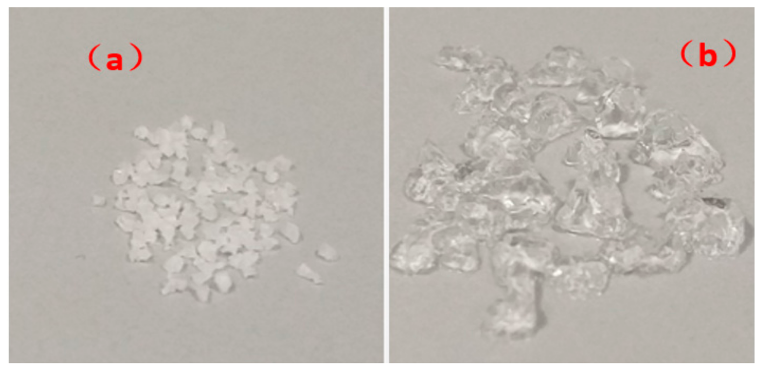
2.1. Materials
2.2. Methods
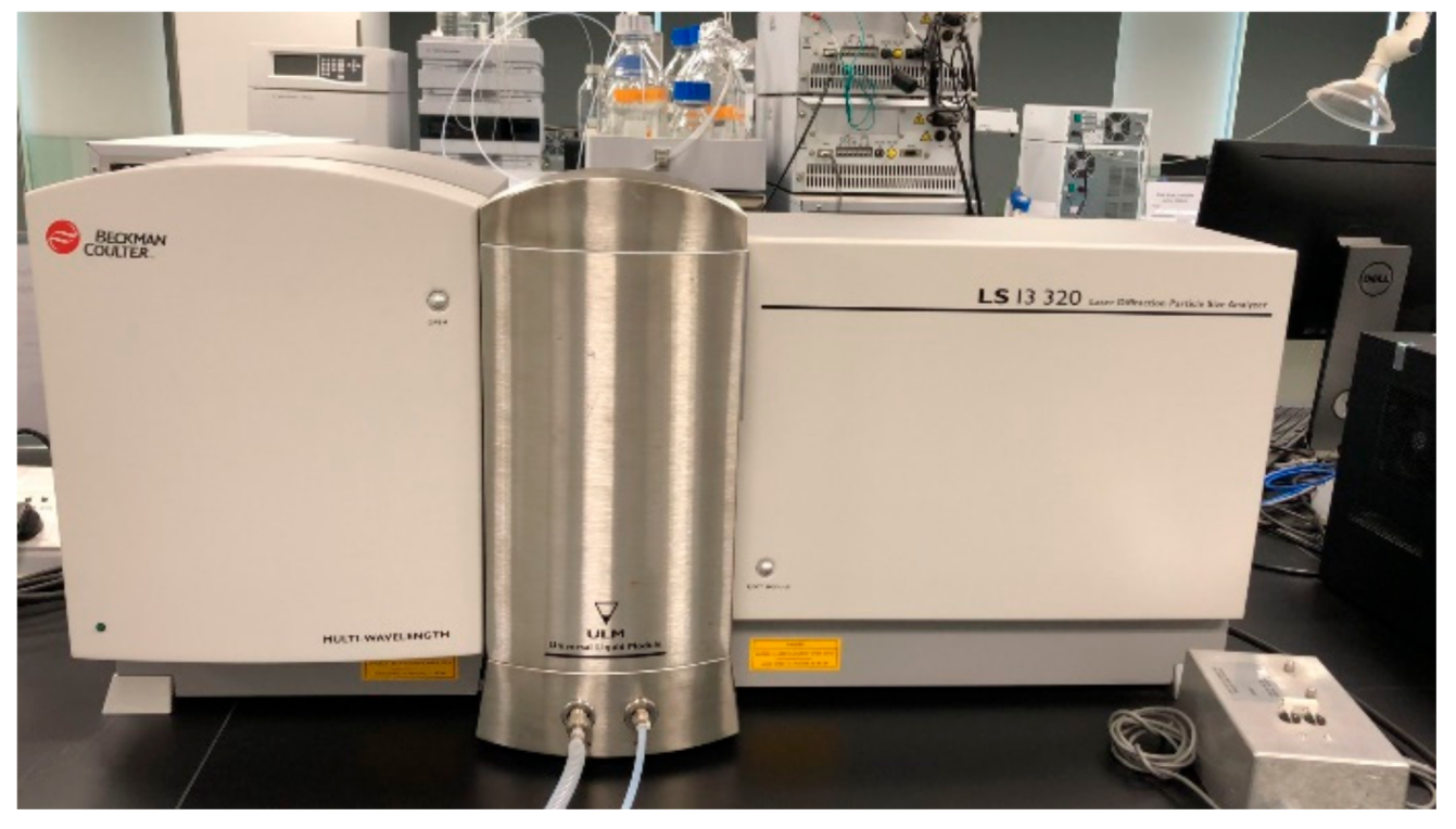
2.2.1. Sand Pack Preparation and Property Determination
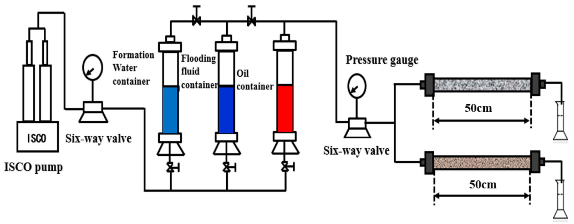
2.2.2. Parallel Sand Pack Flooding Experiment
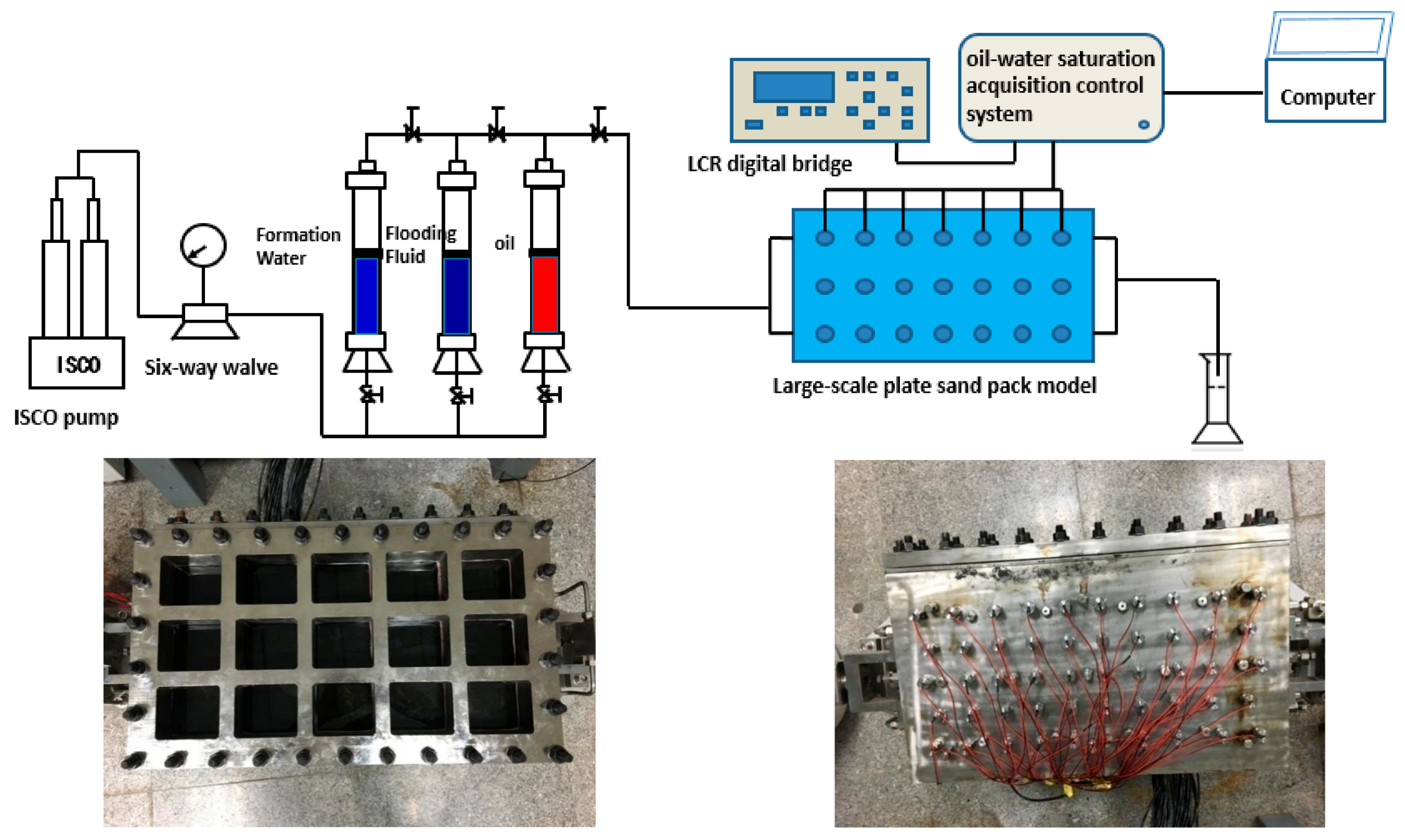
2.2.3. Large-Scale Plate Sand Pack Flooding Experiments
3. Results and Discussion
3.1. Enhanced Oil Recovery of Heterogeneous Phase Combination Flooding System
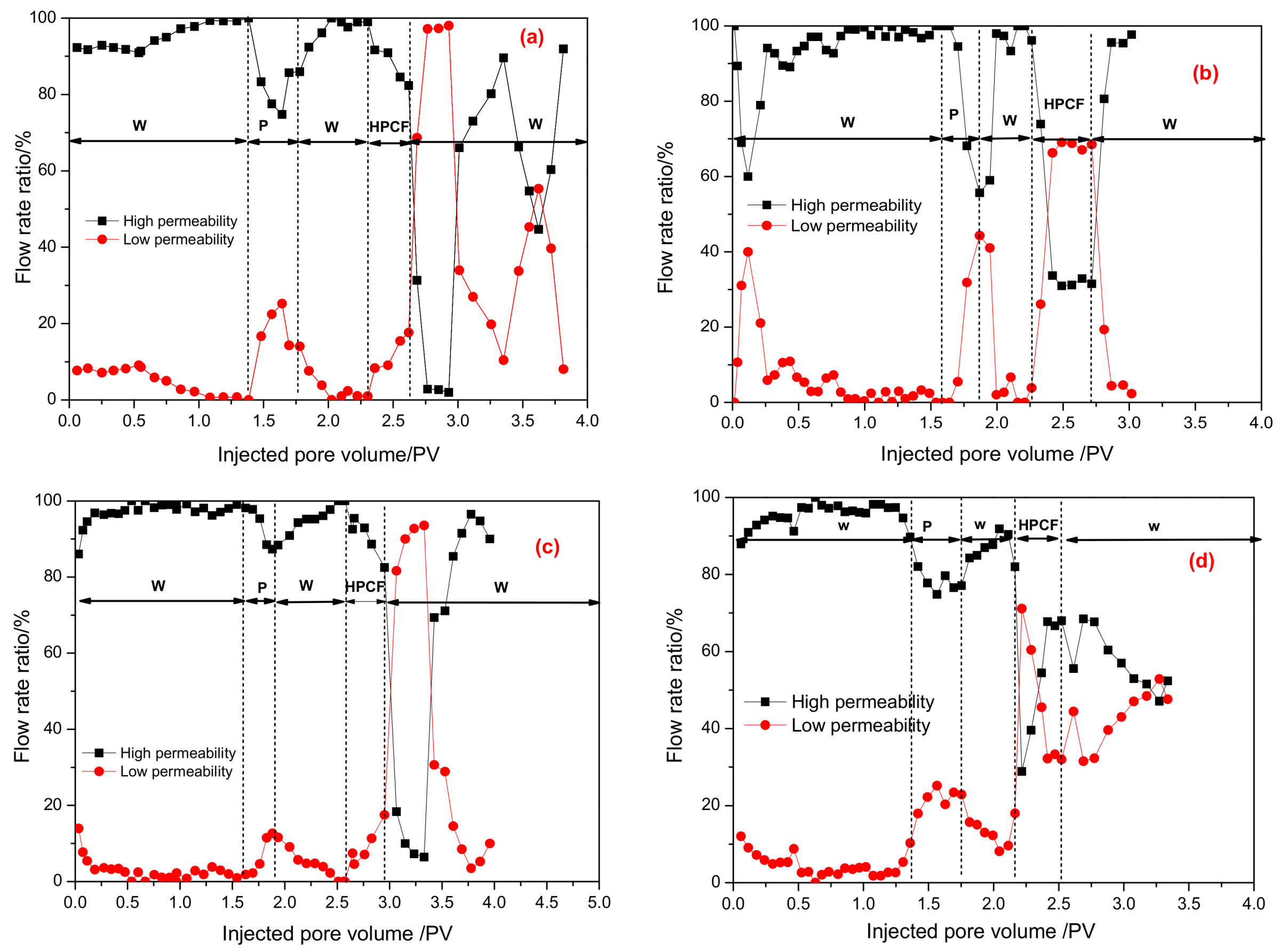
3.1.1. Flow Rate Ratio Analysis
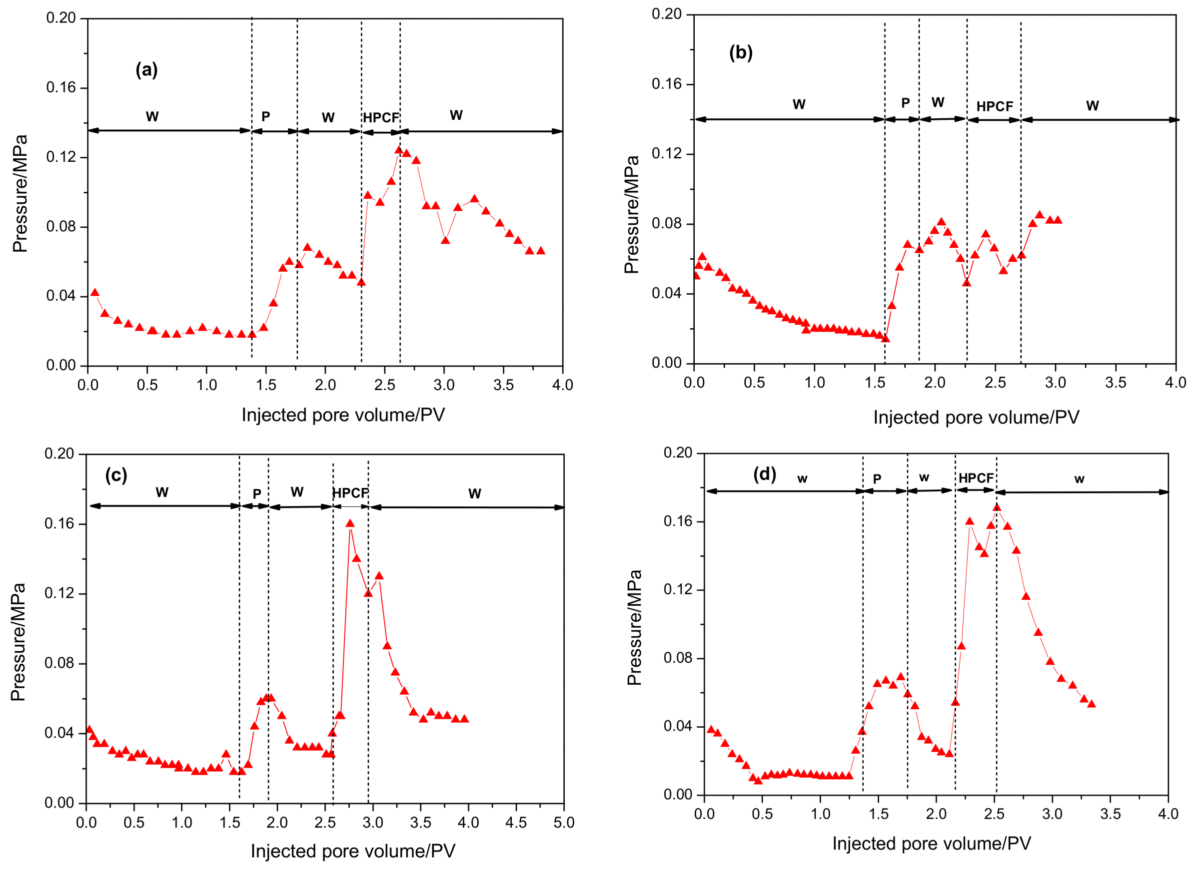
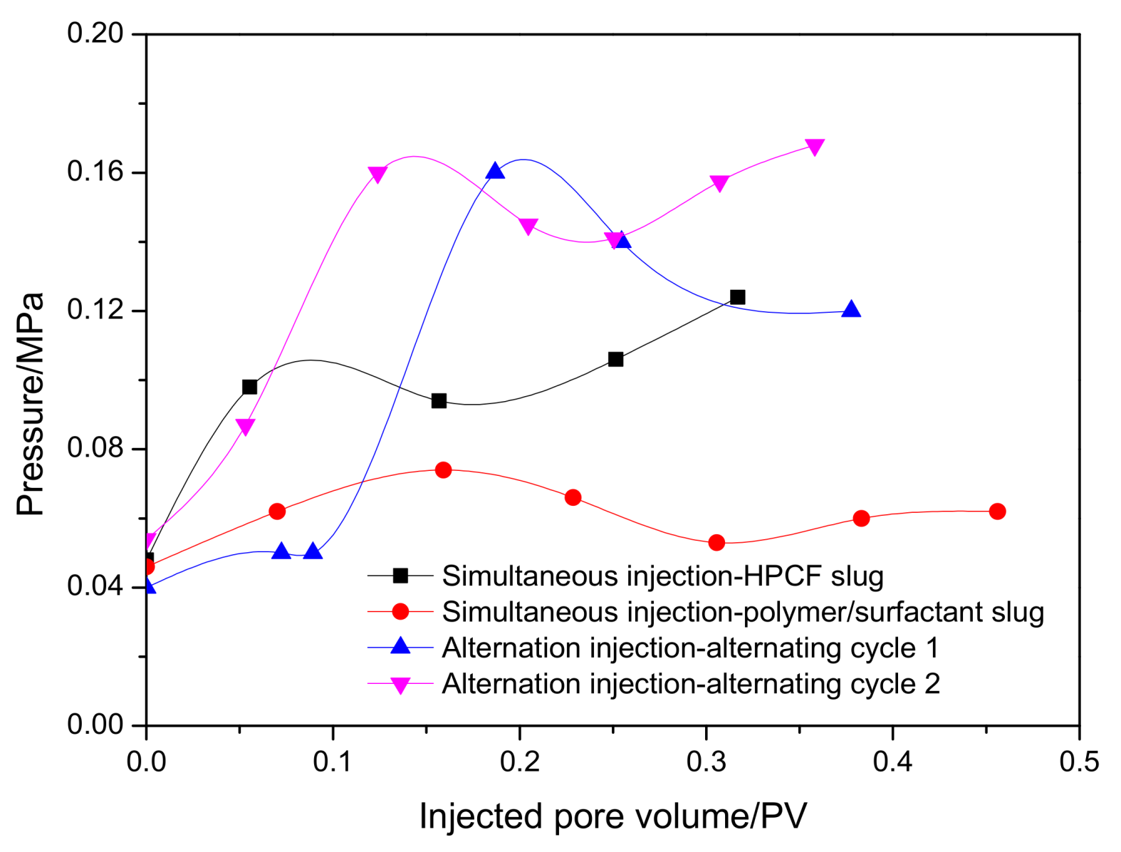
3.1.2. The Injection Pressure Drop Change during HPCF Flooding Period
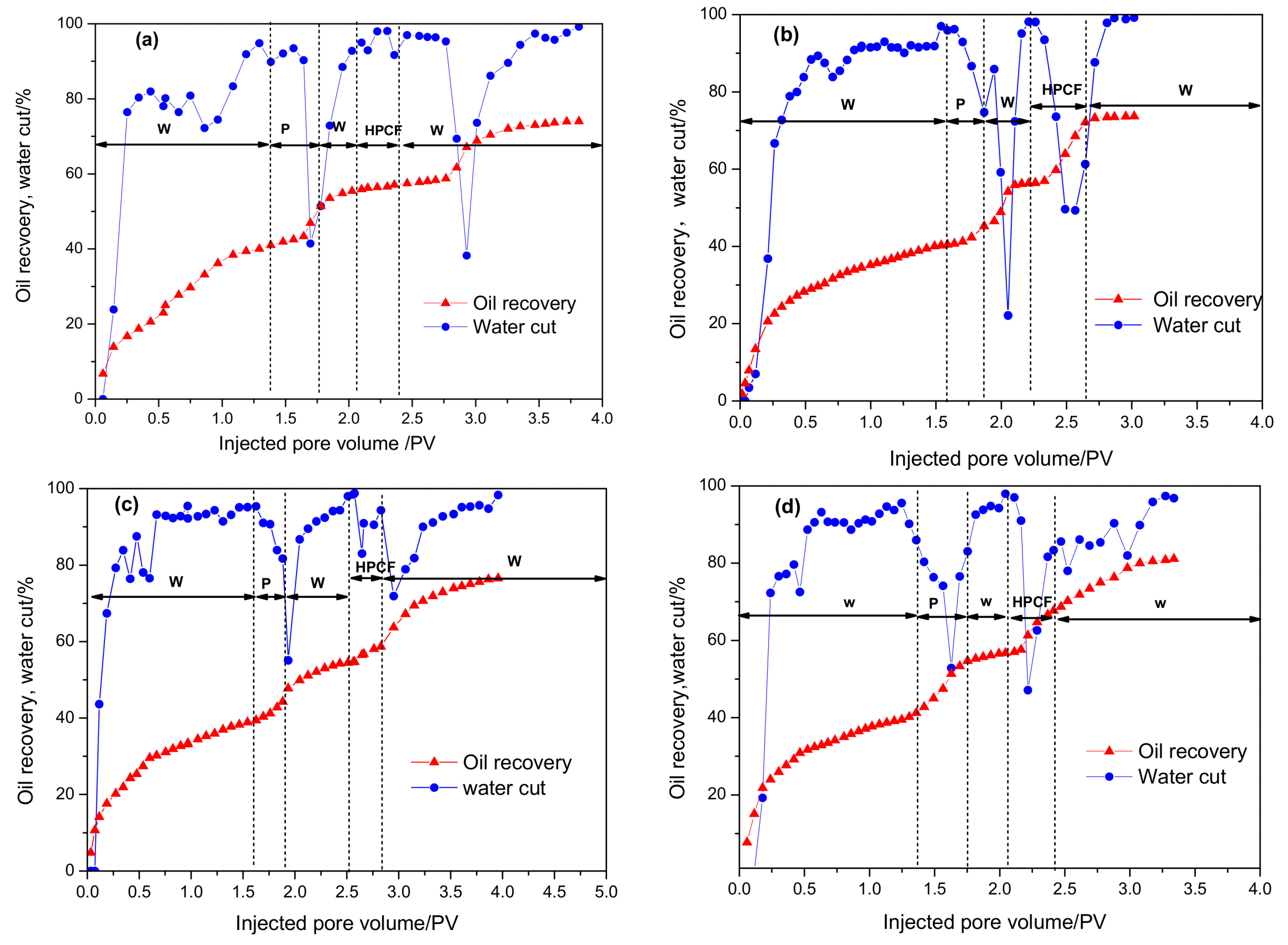
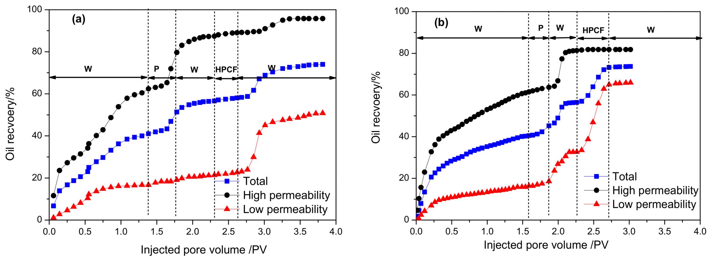
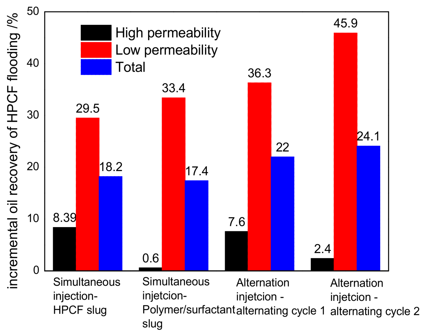
3.1.3. Enhanced Oil Recovery Ability
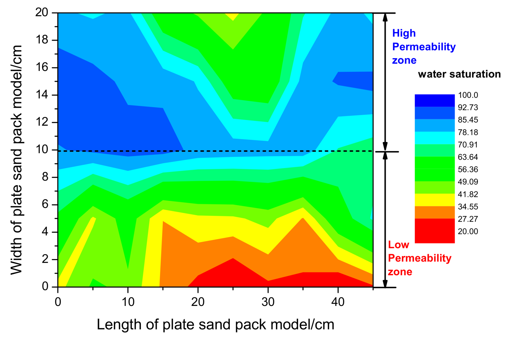
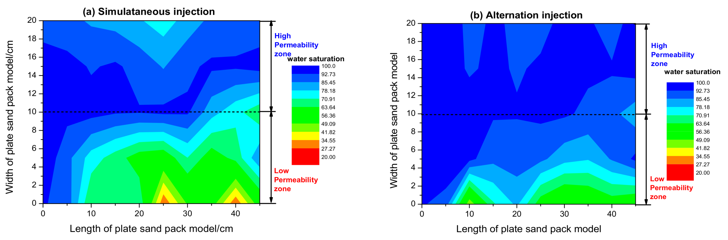
3.2. The Remaining Oil Distribution at Different Flooding Stages
3.2.1. Water Flooding Period
3.2.2. Polymer Flooding Period
3.2.3. Heterogeneous Phase Combination Flooding Period
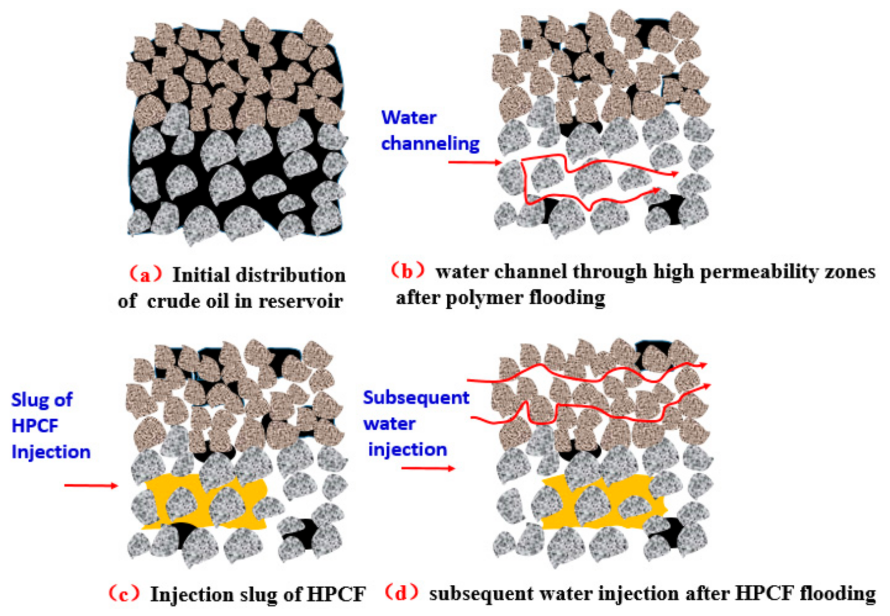
3.3. Potential EOR Mechanism of HPCF after Polymer Flooding in Heterogeneous Reservoirs
4. Conclusions
Author Contributions
Funding
Conflicts of Interest
References
- Liu, Y.; Bai, B.; Wang, Y. Applied Technologies and Prospects of Conformance Control Treatments in China. Oil Gas Sci. Technol. 2010, 65, 859–878. [Google Scholar] [CrossRef] [Green Version]
- You, Q.; Wang, H.; Zhang, Y.; Liu, Y.; Fang, J.; Dai, C. Experimental study on spontaneous imbibition of recycled fracturing flow-back fluid to enhance oil recovery in low permeability sandstone reservoirs. J. Pet. Sci. Eng. 2018, 166, 270–278. [Google Scholar] [CrossRef]
- Liu, S.; Wang, J.; He, H.; Wang, H. Mechanism on Imbibition of Fracturing Fluid in Nanopore. Nanosci. Nanotechnol. Lett. 2018, 10, 87–93. [Google Scholar] [CrossRef]
- Sydansk, R.D.; Southwell, G.P. More than 12 Years’ Experience with a Successful Conformance-Control Polymer-Gel Technology. AAPG Bull. 1998, 15, 270–278. [Google Scholar]
- Chung, T.; Bae, W.; Nguyen, N.T.B.; Dang, C.T.Q.; Lee, W.; Jung, B. A Review of Polymer Conformance Treatment: A Successful Guideline for Water Control in Mature Fields. Energy Sources 2011, 34, 122–133. [Google Scholar] [CrossRef]
- Bai, B.; Zhou, J.; Yin, M. A comprehensive review of polyacrylamide polymer gels for conformance control. Pet. Explor. Dev. 2015, 42, 525–532. [Google Scholar] [CrossRef]
- Wang, D.; Han, P.; Shao, Z.; Hou, W.; Seright, R.S. Sweep-improvement options for the Daqing oil field. SPE Reserv. Eval. Eng. 2008, 11, 18–26. [Google Scholar] [CrossRef]
- Zhang, Y.; Yue, X.; Dong, J.; Yu, L. New and effective foam flooding to recover oil in heterogeneous reservoir. In Proceedings of the SPE/DOE Improved Oil Recovery Symposium, Tulsa, OK, USA, 3–5 April 2000. [Google Scholar]
- Zhang, Z.; Li, J.; Zhou, J. Microscopic roles of “viscoelasticity” in HPMA polymer flooding for EOR. Transp. Porous Media 2011, 86, 199–214. [Google Scholar] [CrossRef]
- Shen, P.; Wang, J.; Yuan, S.; Zhong, T.; Jia, X. Study of enhanced-oil-recovery mechanism of alkali/surfactant/polymer flooding in porous media from experiments. SPE J. 2009, 14, 237–244. [Google Scholar] [CrossRef]
- Hongyan, W.; Xulong, C.; Jichao, Z.; Aimei, Z. Development and application of dilute surfactant–polymer flooding system for Shengli oilfield. J. Pet. Sci. Eng. 2009, 65, 45–50. [Google Scholar] [CrossRef]
- Vargo, J.; Turner, J.; Bob, V.; Pitts, M.J.; Wyatt, K.; Surkalo, H.; Patterson, D. Alkaline-Surfactant-Polymer Flooding of the Cambridge Minnelusa Field. SPE Reserv. Eval. Eng. 2000, 3, 552–558. [Google Scholar] [CrossRef]
- Liu, S.; Zhang, D.; Yan, W.; Puerto, M.; Hirasaki, G.J.; Miller, C.A. Favorable attributes of alkaline-surfactant-polymer flooding. SPE J. 2008, 13, 5–16. [Google Scholar] [CrossRef]
- Olajire, A.A. Review of ASP EOR (alkaline surfactant polymer enhanced oil recovery) technology in the petroleum industry: Prospects and challenges. Energy 2014, 77, 963–982. [Google Scholar] [CrossRef]
- Hou, Q.; Zhu, Y.; Luo, Y.; Weng, R. Studies on foam flooding EOR technique for daqing reservoirs after polymer flooding. In Proceedings of the SPE Improved Oil Recovery Symposium, Tulsa, OK, USA, 14–18 April 2012; Society of Petroleum Engineers: Houston, TX, USA, 2012. [Google Scholar]
- Wang, D.; Cheng, J.; Yang, Z.; Qun, L.; Wu, W.; Yu, H. Successful field test of the first ultra-low interfacial tension foam flood. In Proceedings of the SPE Asia Pacific Improved Oil Recovery Conference, Kuala Lumpur, Malaysia, 6–9 October 2001; Society of Petroleum Engineers: Houston, TX, USA, 2001. [Google Scholar]
- Wang, D.; Hou, Q.; Luo, Y.; Zhu, Y.; Fan, H. Feasibility Studies on CO2 Foam Flooding EOR Technique after Polymer Flooding for Daqing Reservoirs. J. Dispers. Sci. Technol. 2015, 36, 453–461. [Google Scholar] [CrossRef]
- Cao, R.; Yang, H.; Sun, W.; Ma, Y.Z. A new laboratory study on alternate injection of high strength foam and ultra-low interfacial tension foam to enhance oil recovery. J. Pet. Sci. Eng. 2015, 125, 75–89. [Google Scholar] [CrossRef]
- Chen, X.; Feng, Q.; Sepehrnoori, K.; Goudarzi, A.; Bai, B. Mechanistic modeling of gel microsphere surfactant displacement for enhanced oil recovery after polymer flooding. In Proceedings of the SPE/IATMI Asia Pacific Oil & Gas Conference and Exhibition, Nusa Dua, Bali, Indonesia, 20–22 October 2015. [Google Scholar]
- Chen, X.; Feng, Q.; Liu, W.; Sepehrnoori, K. Modeling preformed particle gel surfactant combined flooding for enhanced oil recovery after polymer flooding. Fuel 2017, 194, 42–49. [Google Scholar] [CrossRef]
- Jia, H.; Pu, W.F.; Zhao, J.Z.; Liao, R. Experimental Investigation of the Novel Phenol−Formaldehyde Cross-Linking HPAM Gel System: Based on the Secondary Cross-Linking Method of Organic Cross-Linkers and Its Gelation Performance Study after Flowing through Porous Media. Energy Fuels 2011, 25, 727–736. [Google Scholar] [CrossRef]
- He, H.; Wang, Y.; Zhang, J. Novel Gel with Controllable Strength for In-Depth Conformance Control: Bulk Gelation Performance and Propagation Properties in Porous Media. J. Dispers. Sci. Technol. 2015, 36, 626–633. [Google Scholar] [CrossRef]
- Zhang, J.; He, H.; Wang, Y.; Xu, X.; Zhu, Y.; Li, R. Gelation Performance and Microstructure Study of Chromium Gel and Phenolic Resin Gel in Bulk and Porous Media. J. Energy Resour. Technol. 2014, 136, 042903. [Google Scholar] [CrossRef]
- He, H.; Wang, Y.; Zhang, J.; Xu, X.; Zhu, Y.; Bai, S. Comparison of Gelation Behavior and Morphology of Resorcinol–Hexamethylenetetramine–HPAM Gel in Bulk and Porous Media. Transp. Porous Media 2015, 109, 377–392. [Google Scholar] [CrossRef]
- Bai, B.; Li, L.; Liu, Y.; Liu, H.; Wang, Z.; You, C. Preformed Particle Gel for Conformance Control: Factors Affecting its Properties and Applications. SPE Reserv. Eval. Eng. 2007, 10, 415–421. [Google Scholar] [CrossRef]
- Cui, X.; Li, Z.; Cao, X.; Song, X.; Chen, X.; Zhang, X. A novel PPG enhanced surfactant-polymer system for EOR. In Proceedings of the SPE Enhanced Oil Recovery Conference, Kuala Lumpur, Malaysia, 19–21 July 2011. [Google Scholar]
- Cao, X. Design and Performance Evaluation on the Heterogeneous Combination Flooding System. Acta Pet. Sin. 2013, 29, 115–121. [Google Scholar]
- Sang, Q.; Li, Y.; Yu, L.; Li, Z.; Dong, M. Enhanced oil recovery by branched-preformed particle gel injection in parallel-sandpack models. Fuel 2014, 136, 295–306. [Google Scholar] [CrossRef]
- Gong, H.; Zhang, H.; Xu, L.; Li, K.; Yu, L.; Li, Y.; Dong, M. Further enhanced oil recovery by branched-preformed particle gel/HPAM/surfactant mixed solutions after polymer flooding in parallel-sandpack models. RSC Adv. 2017, 7, 39564–39575. [Google Scholar] [CrossRef] [Green Version]
- Gong, H.; Zhang, H.; Xu, L.; Li, K.; Yu, L.; Qian, S.; Li, Y.; Dong, M. The Synergistic Effect of Branched-Preformed Particle Gel and Hydrolyzed Polyacrylamide on Further-Enhanced Oil Recovery after Polymer Flooding. Energy Fuels 2017, 31, 7904–7910. [Google Scholar] [CrossRef]
- Cao, X.; Guo, L.; Wang, H.; Wei, C.; Liu, Y. The Study and Pilot on Heterogeneous Combination Flooding System for High Recovery Percent of Reservoirs after Polymer Flooding. In Proceedings of the 22nd World Petroleum Congress, Istanbul, Turkey, 9–13 July 2017; World Petroleum Congress: London, UK, 2017. [Google Scholar]
- He, H.; Wang, Y.; Qi, Z.; Sun, X. Gelation Performance and Feasibility Study of an Environmental Friendly Improved Inorganic Aluminum Gel for Conformance Control under Harsh Reservoir Conditions. J. Energy Resour. Technol. 2016, 139, 012911. [Google Scholar] [CrossRef]


| Injection Mode | Main Slug | Viscosity (mPa·s) | |
|---|---|---|---|
| Simultaneous injection | P + B-PPG + S (HPCF) slug | 1200 mg·L−1 Polymer + 1200 mg·L−1 B-PPG + 0.4 wt % Surfactant | 60.0 |
| SP slug | 1500 mg·L−1 Polymer + 0.4 wt % Surfactant | 48.0 | |
| Alternation injection | P + B-PPG + S (HPCF) slug alternating SP slug | 1200 mg·L−1 Polymer + 1200 mg·L−1 B-PPG + 0.4 wt % Surfactant | 60.0 |
| 1200 mg·L−1 Polymer + 0.4 wt % Surfactant | 42.0 | ||
| Injection Mode | Slug of Heterogeneous Combination Flooding System (HPCF) | |||
|---|---|---|---|---|
| Pre-Slug | Main Slug 1 | |||
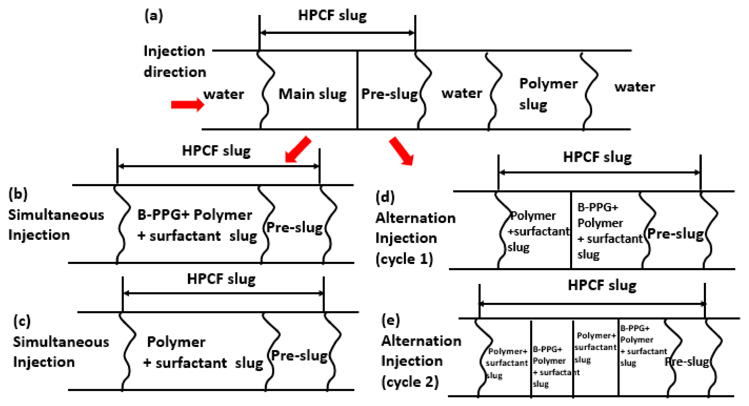
| Simultaneous injection | polymer and B-PPG slug (P + B-PPG) | 0.05 PV (1500 mg·L−1 Polymer + 1500 mg·L−1 B-PPG) | heterogeneous combination flooding slug (P + B-PPG + S) | 0.30 PV (1200 mg·L−1 Polymer + 1200 mg·L−1 B-PPG + 0.4 wt % Surfactant) |
| polymer and B-PPG slug (P + B-PPG) | 0.05 PV (1500 mg·L−1 Polymer + 1500 mg·L−1 B-PPG) | Polymer and surfactant slug (SP) | 0.41 PV (1500 mg·L−1 Polymer + 0.4 wt % Surfactant) | |
| Alternation injection | polymer and B-PPG slug (P + B-PPG) | 0.05 PV (1500 mg·L−1 Polymer + 1500 mg·L−1 B-PPG) | (P + B-PPG + S) slug alternating (SP) slug | 0.173 PV HPCF (1200 mg·L−1 Polymer + 1200 mg·L−1 B-PPG + 0.4 wt % Surfactant) + 0.173 PV SP (1200 mg·L−1 Polymer + 0.4 wt % Surfactant) (alternating cycle 1) |
| polymer and B-PPG slug (P + B-PPG) | 0.05 PV (1500 mg·L−1 Polymer + 1500 mg·L–1 B-PPG) | (P + B-PPG + S) slug alternating (SP) slug | 0.0865 PV HPCF + 0.0865 PV SP (alternating cycle 2) | |
| Injection Mode | Main Slug | Sand Packs | Permeability (μm2) | Porosity (%) | Soi (%) |
|---|---|---|---|---|---|
| Simultaneous injection | 0.30 PV (1200 mg·L–1 Polymer + 1200 mg·L–1 B-PPG + 0.4 wt % Surfactant) | High permeability | 4.27 | 57.1 | 90.0 |
| Low Permeability | 1.17 | 48.9 | 88.6 | ||
| 0.41 PV (1500 mg·L−1 Polymer + 0.4 wt % Surfactant) | High permeability | 4.33 | 41.6 | 87.8 | |
| Low Permeability | 1.26 | 40.0 | 80.4 | ||
| Alternation injection | 0.173 PV HPCF + 0.173 PV SP (alternating cycle 1) | High permeability | 4.36 | 56.3 | 81.8 |
| Low Permeability | 1.27 | 51.4 | 68.2 | ||
| 0.0865 PV HPCF + 0.0865 PV SP (alternating cycle 2) | High permeability | 4.12 | 40.7 | 80.0 | |
| Low Permeability | 1.22 | 39.1 | 70.0 |
| Injection Strategy | Sand Pack Type | Enhanced Oil Recovery (% OOIP) | ||||
|---|---|---|---|---|---|---|
| Water Flooding | After Polymer Flooding | After HPCF Flooding | Incremental Recovery of Polymer Flooding | Incremental Recovery of HPCF Flooding | ||
| Simultaneous injection—HPCF flooding | High permeability | 62.4 | 87.4 | 95.8 | 25 | 8.39 |
| Low permeability | 16.6 | 21.3 | 50.8 | 4.7 | 29.5 | |
| Total | 41 | 56.6 | 74.8 | 15.6 | 18.2 | |
| Simultaneous injection—SP flooding | High permeability | 61.5 | 81.2 | 81.8 | 19.7 | 0.6 |
| Low permeability | 15.8 | 32.5 | 65.9 | 16.7 | 33.4 | |
| Total | 40.5 | 56.3 | 73.7 | 15.8 | 17.4 | |
| Alternation injection—alternating cycle 1 | High permeability | 56 | 80.7 | 88.3 | 24.7 | 7.6 |
| Low permeability | 11.7 | 26.5 | 62.8 | 14.8 | 36.3 | |
| Total | 39.4 | 54.5 | 76.5 | 15.1 | 22.0 | |
| Alternation injection—alternating cycle 2 | High permeability | 60.7 | 79.7 | 82.1 | 19.0 | 2.4 |
| Low permeability | 17.1 | 33.5 | 79.4 | 16.4 | 45.9 | |
| Total | 39.5 | 57 | 81.1 | 17.5 | 24.1 | |
© 2018 by the authors. Licensee MDPI, Basel, Switzerland. This article is an open access article distributed under the terms and conditions of the Creative Commons Attribution (CC BY) license (http://creativecommons.org/licenses/by/4.0/).
Share and Cite
He, H.; Fu, J.; Hou, B.; Yuan, F.; Guo, L.; Li, Z.; You, Q. Investigation of Injection Strategy of Branched-Preformed Particle Gel/Polymer/Surfactant for Enhanced Oil Recovery after Polymer Flooding in Heterogeneous Reservoirs. Energies 2018, 11, 1950. https://doi.org/10.3390/en11081950
He H, Fu J, Hou B, Yuan F, Guo L, Li Z, You Q. Investigation of Injection Strategy of Branched-Preformed Particle Gel/Polymer/Surfactant for Enhanced Oil Recovery after Polymer Flooding in Heterogeneous Reservoirs. Energies. 2018; 11(8):1950. https://doi.org/10.3390/en11081950
Chicago/Turabian StyleHe, Hong, Jingyu Fu, Baofeng Hou, Fuqing Yuan, Lanlei Guo, Zongyang Li, and Qing You. 2018. "Investigation of Injection Strategy of Branched-Preformed Particle Gel/Polymer/Surfactant for Enhanced Oil Recovery after Polymer Flooding in Heterogeneous Reservoirs" Energies 11, no. 8: 1950. https://doi.org/10.3390/en11081950