Tri-Axial Shear Tests on Hydrate-Bearing Sediments during Hydrate Dissociation with Depressurization
by
 , ,
, ,
Dongliang Li
1,2,3,4 ,
,
Qi Wu
1,2,3,4,5,
Zhe Wang
1,2,3,4,6,
Jingsheng Lu
1,2,3,4,
Deqing Liang
1,2,3,4,* and
Xiaosen Li
1,2,3,4 1
Guangzhou Institute of Energy Conversion, Chinese Academy of Sciences, Guangzhou 510640, China
2
CAS Key Laboratory of Gas Hydrate, Guangzhou 510640, China
3
Guangdong Provincial Key Laboratory of New and Renewable Energy Research and Development, Guangzhou 510640, China
4
Guangzhou Center for Gas Hydrate Research, Chinese Academy of Sciences, Guangzhou 510640, China
5
University of Chinese Academy of Sciences, Beijing 100049, China
6
Nano Science and Technology Institute, University of Science and Technology of China, Suzhou 215123, China
*
Author to whom correspondence should be addressed.
Energies 2018, 11(7), 1819; https://doi.org/10.3390/en11071819
Submission received: 3 May 2018
/
Revised: 21 June 2018
/
Accepted: 7 July 2018
/
Published: 11 July 2018
Abstract
:A series of tri-axial shear tests were carried out to determine the stress and strain characteristics, as well as the volume deformation of methane hydrate-bearing sediments during gas hydrate dissociation. An innovative type of depressurization was adopted with a high-pressure and low-temperature tri-axial apparatus. Results show that: (1) decrease in pore pressure during the shear process may result in the failure of hydrate-bearing sediments, but they did not collapse completely due to high effective confining pressure; (2) depressurization leads to the contraction of volumetric strain and the ultimate deformation shows no difference compared to that prior depressurization; (3) high saturation hydrate-bearing sediments were more sensitive to depressurization, which could be due to the methane hydrate acting as a skeleton structure at some sites when the pore hydrates’ saturation is high.
1. Introduction
Natural gas hydrates (NGH) are cage crystalline compounds of natural gas and water, which are stable under certain temperature and pressure conditions. With the discovery of gas hydrates in permafrost regions and the deep ocean, there is great interest in NGH as a potential energy resource for the 21st century. Estimates of natural gas amounts available from NGH are 9 × 10¹⁵ m3 and the amount of organic carbon in it greatly exceeds that of any other source of the global carbon cycle [1]. Therefore, developing methods for the commercial production of natural gas from hydrate reservoirs is attracting considerable attention. At present, four primary exploitation methods (depressurization, heat injection, chemical injection, and CO2 displacement recovery) for NGH have been proposed, and the depressurization method is the most promising technique for future production [2]. However, there are still several issues to be studied regarding engineering and geological safety during exploitation. One challenge to overcome is the possible seafloor subsidence or landslides brought about by a loss of strength as hydrates dissociate from sediment [3]. In geophysics research investigating the strength and rheology of pure methane hydrates, it was reported that methane hydrates are over 20 times stronger than ice at the same conditions and strain rate [4], highlighting the importance of understanding the mechanical properties of natural hydrates.
Direct sampling requires sophisticated coring technology and subsequent laboratory tests may destroy in-situ properties [5]. Masui et al. [6] conducted a series of tri-axial shear tests on NGH with marine sediment samples. They proved that NGH can significantly increase strength and shear modulus, and that there was no evidence that hydrate saturation had an effect on Poisson’s ratio. In addition, core samples and laboratory synthesis samples exhibited similar mechanical properties. Hyodo et al. [7] reported that different pressures and temperatures of hydrate-bearing sediment formations do not change the strength of the generated methane hydrates. The frequently discussed hydrate habits (pore filling, load bearing, and cementation) are related to hydrate saturation and can be customized by different laboratory methods [8]. These results illustrate that laboratory measurements of synthetic samples can solve the problem of hydrate extraction securely, effectively, and economically.
A conventional soil mechanics tri-axial shear apparatus to add a temperature and pressure control device was invented to study the mechanical characteristics of hydrate-bearing sediments. The sediment types [9], particle size [10], temperature [7], pressure (core pressure and confining pressure) [11], and hydrate saturation [12] of the sediments were all previously analyzed. Robust and consistent conclusions included: (1) Different sediment types can signally affect the deformation behavior; (2) increasing fine content of sediments decreased both the initial stiffness and shear strength of sediment samples; (3) pressure and temperature are related to hydrate stability, and pressure has an extremely complex effect on the mechanical characteristics of hydrate-bearing sediments. The shear strength increased with increasing confining pressure, but results might be different in high-pressure (>10 MPa) situations; (4) the existence of hydrates can dramatically enhance strength. Based on these results, sediment particles and experimental conditions selected in situ can obtain more meaningful experimental results. In the actual production process, all parameters changed simultaneously. The mutual relationships among the parameters in hydrate-bearing sediments require additional studies. To meet the requirements of practical exploitation engineering, the study of mechanical properties of hydrate-bearing sediments during simulated mining appear to be particularly important.
Aoki et al. [13] designed a special pressure vessel to study the compaction of methane hydrate-bearing sediment during the dissociation of methane hydrate. The vertical displacement, temperature, and pore pressure were measured during the hydrate dissociation under depressurization conditions. Results of the experiments showed that depressurizing performance for hydrate dissociation was the major reason for final deformation. Hyodo et al. [7,14] studied the properties of hydrate and/or its sand mixtures with a low temperature and high confining pressure tri-axial compression apparatus. Results indicated that the degree of hydrate saturation can influence the change in volume, and the different hydrate dissociation methods that are performed. It was found that depressurization rate does not have a tremendous effect on the final deformation of methane hydrate-bearing sediments, but the initial deformation rate increases with increasing depressurization velocity. In addition, axial and volumetric strain will be enlarged by reducing pore pressure increases. Hydrate interaction with sands is also strongly dependent on morphology and the way it forms. Priest et al. [15] found that gas hydrate formed in sands using “excess water” and “excess gas” technique exhibits a frame supporting and cementing behavior, respectively. Miyazaki et al. [16] suggested that the stiffness of artificial methane-hydrate-bearing sediment affected by the type of sand forming the skeleton of the specimens. Dai et al. [17] found that the hydraulically, thermally and mechanically properties of hydrate-bearing sediments depend on hydrate saturation as well as hydrate distribution and morphology.
Numerical simulations have also investigated these issues. Kimoto et al. [18] discussed a chemo-thermo-mechanically coupled simulation method to research formation stability during hydrate dissociation. Remarkable deformations were predicted in the dissociation process due to changes in pore pressure, especially for the depressurization method. Rutqvist et al. [19] studied the geo-mechanical response during depressurization. Simulation results indicated that the effective shear stress increased during depressurization, primarily due to increases in vertical effective stress as opposed to horizontal effective stress. More experiments regarding the mechanical characteristics of methane hydrate-bearing sediment under depressurization are required.
In this work, a series of tri-axial shear tests were carried out to investigate the mechanical properties of methane hydrate-bearing sediments during dissociation using the depressurization method. To do so, an innovative type of depressurization method was adopted.
2. Materials and Methods
2.1. Experimental Apparatus
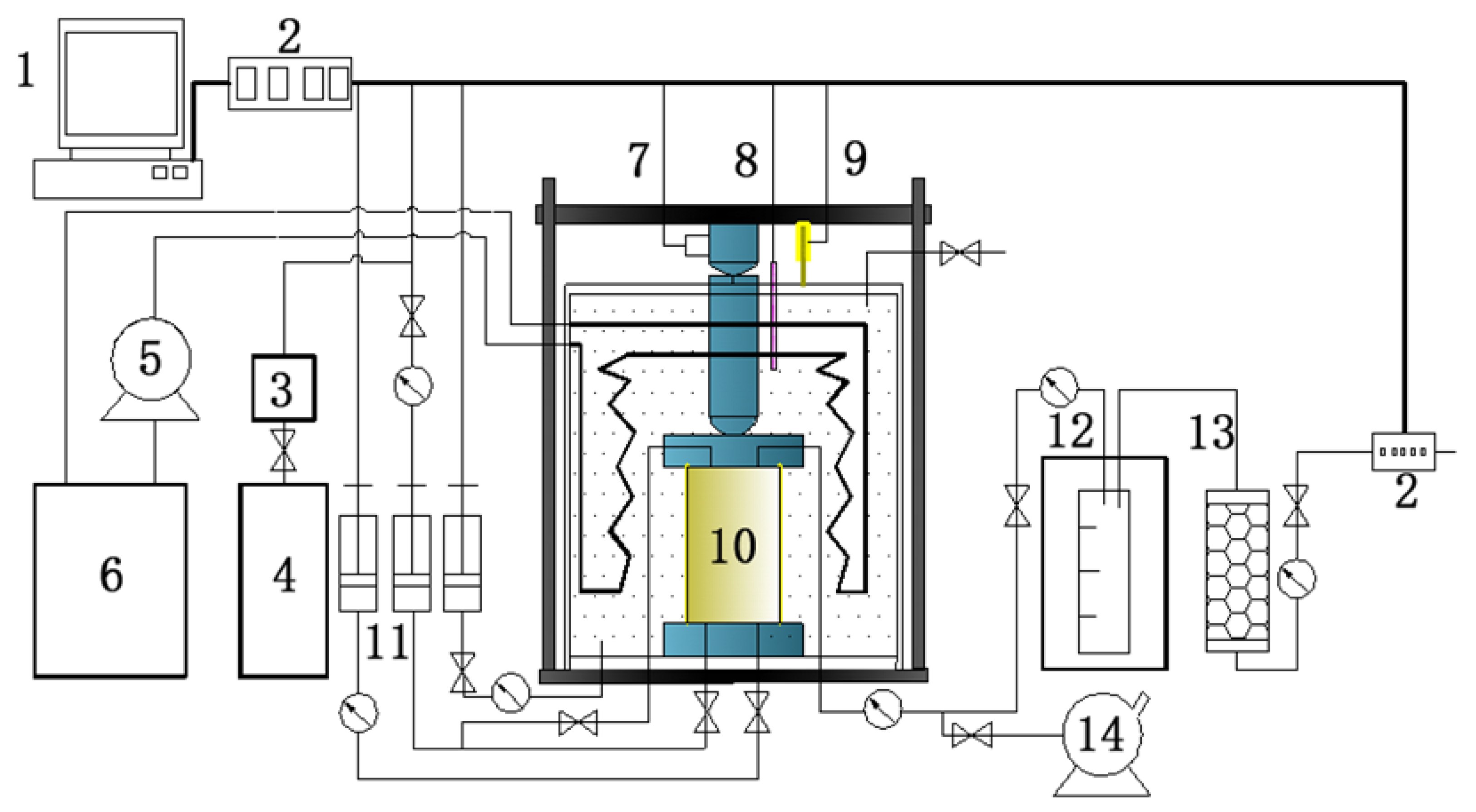
To study the mechanical characteristics of methane hydrate-bearing sediments, high-pressure and low-temperature tri-axial equipment was developed. The schematic diagram of the instrument is shown in Figure 1. The specimen size was 50 × 100 mm and the core and confining pressures were controlled within 30 MPa with an accuracy of ±0.1 MPa. The temperature was controlled by a circulating fluid constant temperature system, which can be carried out in a range from 243.15 to 323.15 K with an accuracy of ±0.5 K. Both pressure and temperature were monitored by sensors. Reconstituted methane hydrate-bearing sediments can be synthesized in situ. A two-way gas inflow method was adapted to ensure sufficient gas injection. An axial loading system can provide a stable load capacity of 250 KN with accuracy up to 1/1000th of the full-scale load. A cryogenic liquid injection pump was used to provide and measure the injected water. To monitor variations in volume, a piston pressure cell was adopted as a syringe pump to supply the confining pressure. The confining pressure chamber was connected to the piston pressure cell and the volume change of the sample was measured by the piston position. In addition, the gas quantity was recorded by a wet gas flowmeter which supplied by Shanghai Kehormatan Industry Co. (Shanghai, China, BSD 0.5 type, the measurement range of 0.005–0.5 m3/h, ±1%) and a video camera was employed to record the real time gas production.
2.2. Experimental Procedure and Test Conditions
2.2.1. Hydrate Formation and Water Substitution Process
Quartz sands collected from the cores of the South China Sea hydrate drilling area were chosen as the host sediments in this study. The grain size dispersion of the host sand are shown in Figure 2 and the porosity was approximately 35%.
All shear tests used a synthesized hydrate-bearing sediment. First, dried sand and a certain amount of deionized water were mixed until the water dispersion was nearly uniform. The initial mass ratio of water to sand was 1:11. Next, water-bearing sand was inserted into the sample model (50 mm in diameter and 100 mm in height) and compacted with a tamper. After that, the vacuum program was carried out to make the sample have initial stiffness and expel the air in the sand sample. To exclude impacts of the sample synthesis, the formation of the hydrate-bearing sample was consistent. Methane gas was gradually injected into the specimen while the confining pressure was gradually increased to 10 MPa. During this time, the pore pressure was about 1 MPa lower than the confining pressure and the temperature was maintained at 293.15 K for 24 h. Next, the temperature was lowered to 275.15 K to synthesize the methane hydrate. These conditions were kept steady for four days, during which time the water almost completely converted into hydrates. After the formation of methane hydrate was complete, low-temperature (275.15 K) water was injected into the specimen to displace the free methane gas until the sample was saturated. The water was injected into the bottom of the sample at a pressure of 9 MPa, and at the same time the pore pressure at the top of the sample was controlled at about 7 MPa. This process may last for 5 to 8 h. The saturation of methane hydrate was measured by collecting the dissociated methane gas after the shear test. Finally, temperature, pore pressure, and confining pressure were measured to determine the condition of samples.
2.2.2. Shear Tests and Hydrate Dissociation Processes
An initial shear test was conducted under undrained conditions, keeping the confining pressure at a pre-determined value and the temperature at 279.15 K. The loading rate in all of tests was set at 0.2% per min. The detailed experimental parameters and shear conditions are shown in Table 1.
For the depressurization shear test, after the formation of sample, axial loading was conducted. At first, the specimen was sheared to an axial strain of 0.5% (1% or 2.5%) and then the depressurization was conducted. The pore pressure gradually decreased to 3 MPa and subsequently remained constant. During the entire experiment, the axial loading was applied continuously until the axial strain increased to 15%. In addition, two drained shear tests on water saturated sand were carried out for the comparison with the depressurization test. The first one under a confining pressure equal to 10 MPa and pore pressure equal to 3 MPa, the second test under a confining pressure and pore pressure equal to 12 MPa and 3 MPa, respectively.
2.2.3. Saturation Calculation of Hydrates
Here, the Ghiassian method [20] was used to calculate the hydrate content (hydrate saturation) of the sample. It is assumed that per unit volume methane hydrate will produce 164 unit volume of methane gas and 0.87 unit volume of water. The formula for calculation of hydrate saturation is:
where Sh is the hydrate saturation, Vh is the volume of gas hydrate, and Vv is the pore volume.
For the single stage tri-axis shear experiment, the sum of collected methane gas during the whole experiment is L0, so the initial hydrate saturation is given by:
where Sh0 indicates the initial hydrate saturation.
For the multistage tri-axial shear test, the gas volume of the methane hydrate decomposition collected by the first depressurization stage was L1, and the gas volume collected by the second depressurization stage was L2. After the whole test, the total gas volume was L3. The hydrate saturation of the first stage is:
The hydrate saturation of the second stage is,
And the hydrate saturation of the third stage is:
3. Results and Discussion
3.1. The Geotechnics of Methane Hydrate-Bearing Sediments Dissociated by the Depressurization Method
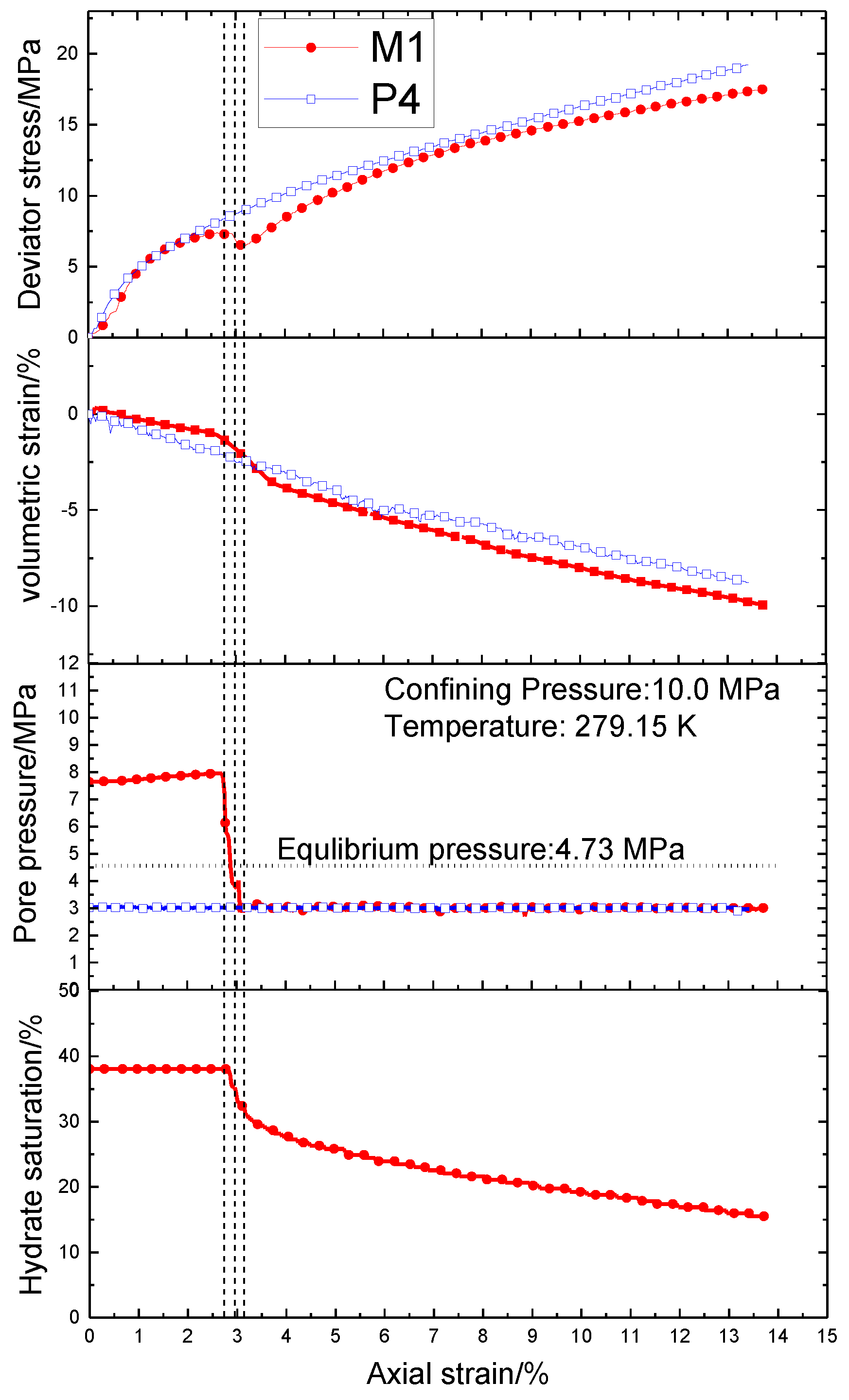
Figure 3 shows variations in axial strain, deviator stress, and volumetric strain under the depressurization method and the drained shear test of water saturated sand.
For the M1, in the initial stages (axial strain from 0 to 1%) of the shear process, the axial strain and deviator stress show an approximately linear relationship, and no significant volume deformation was discovered. The same phenomenon can be found in Hyodo [14]. When the axial strain is between 1 and 2.5%, the volume of the specimen decreased slightly and the axial strain dependency was manifested as an elastic deformation. The initial stages of shear were undrained behavior, so less variation in volumetric strain was observed. Depressurization was carried out when the axial strain reached 2.5%. As pore pressure was reduced, the deviator stress decreased as the axial strain increased, and the volume also began to decrease considerably. At the beginning of depressurization, the reduction of pore pressure was due to the free water draining from the specimen. The dissociation of methane hydrate occurred when the pore pressure was less than 4.73 MPa (phase equilibrium pressure at 279.15 K). At this stage, the pore pressure decreased substantially and continued axial loading resulted in a decline in deviator stress with an increase of axial strain. This implies that failure may occur when pore pressure is reduced during the shear process. For the P4, the effective confining pressure was 7 MPa throughout the whole shear process and the stress-strain relationship of P4 sample shows a strong strain hardening phenomenon. There is no obvious inflection point in the deviator stress line and the stiffness of pure sand sample is similar to that of hydrate-bearing sediments. Although the effective confining pressure of pure sand sample (P4) is much greater than that of hydrate-bearing sediment, the hydrate-bearing sediments sample exhibits higher mechanical strength. Comparing the two samples, we found that the response of hydrate-bearing sediments after partial hydrate decomposition is similar to that of the water saturated sand under the same effective confining pressure. This phenomenon was more significant after the dissociation of hydrate in large quantity at the later stage of the experiment. The final volume of M1 shrinks more than P4 can be observed from the relationship of volumetric strain and axial strain. This may be the result of dissociation of methane hydrate. Hyodo [21] and Li [14] also reported that the methane hydrate-bearing sediment would fail when it dissociates under an axial load between the failure envelops for methane hydrate-bearing sediment and pure sand. When the pore pressure dropped to 3.0 MPa and then remained stable, the deviator stress rose slowly with the increase of axial strain and the speed of volume deformation gradually slowed down. This suggests that the hydrate-bearing specimen did not completely collapse, due to the high effective confining pressure. The phenomenon of strain hardening was clearly observed later in the shearing process.
3.2. Influence of the Stress States at the Start of Depressurization
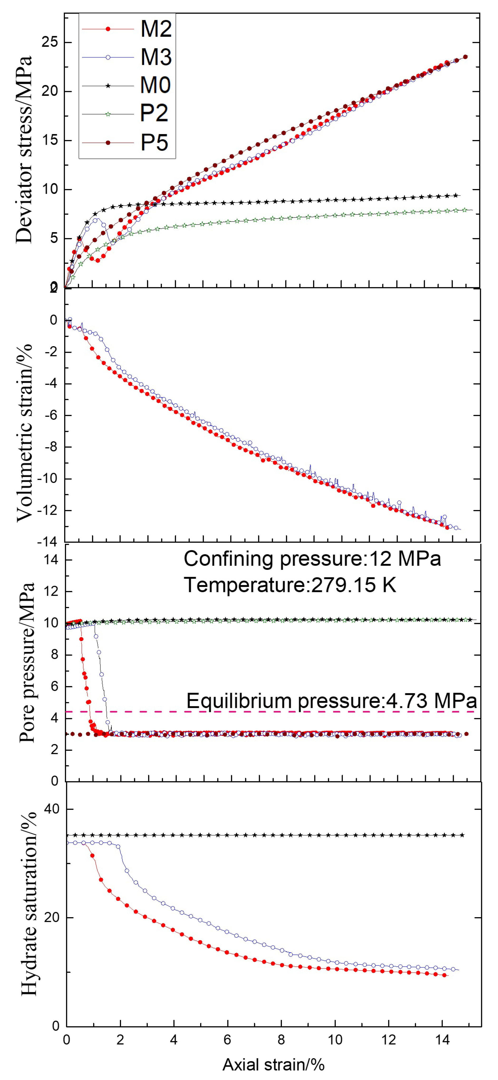
Figure 4 shows the relationship between axial strain, deviator stress, pore pressure, and volumetric strain under various shear conditions. For specimen M2, the depressurization was carried out when the axial strain reached 0.5%. For specimen M3, a similar operation was performed when the axial strain reached 1.0%. Specimen M0 and P2 belonged to the regular tri-axial shear test and the pore of specimen P2 filled with N2. All specimens were under the same temperature (279.15 K) and confining pressure (12.0 MPa) conditions. The hydrate saturation of M0, M2, and M3 were 35.23, 33.82, and 33.82%, respectively. The curves of stress-strain show that different shear test conditions exhibit diverse characteristics. In the case of M0, short compaction stage, elastic stage, yield stage, and long plastic stage were observed in that order. Yan [22] reported a similar result with tri-axial compressive tests on samples of natural gas hydrate-bearing sediment, but the peak strength was not obvious in those experiments. The deviator stress of specimens M2 and M3 decreased during the depressurization process. Since M2 and M3 began at different axial strain rates, their stress states coincided at the beginning of decompression. In the case of M2, the depressurization process started at the axial strain of 0.5% and the stress of hydrate-bearing sediment was lower than the failure stress. In the case of M3, the stress of specimen close to the failure stress but also lower than the failure stress while the axil reached 1%. This implies that depressurization may result in the destruction of hydrate-bearing sediment even if the specimen stress is less than the failure stress. When the pore pressure was stabilized, specimens M2 and M3 exhibited the same residual stress. In addition, both of M2 and M3 are very close to the stress-strain relationship of water saturated sand samples (P5) in the same conditions. Similar to the work of Li [12], the stress state during dissociation had no significant relationship to the residual strength of the dissociated specimen. For the variation in volume, depressurization results in the contraction tendency of volumetric strain because the pore water and methane gas were drained by the release of pore pressure. The increment of effective confining pressure induced the re-compaction of hydrate-bearing sediment after the hydrates’ dissociation. The ultimate deformation was not obvious between the hydrate-bearing sediments M2 and M3.
3.3. Influence of Hydrate Saturation
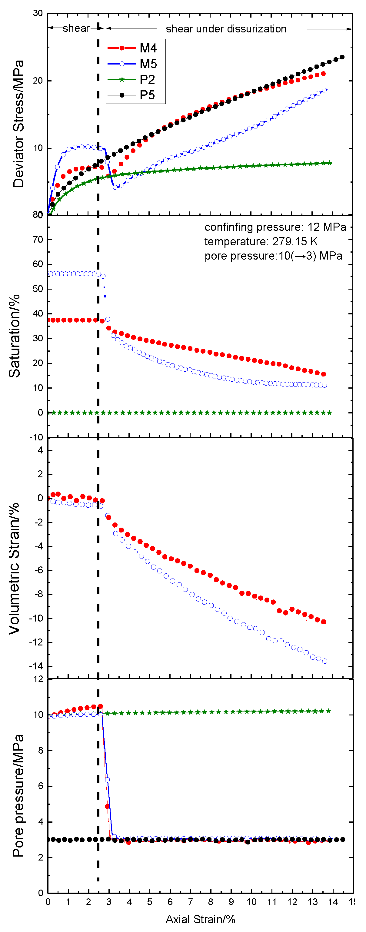
Figure 5 shows the deviator stress, volumetric strain, and axial strain tendencies for various saturation levels of the methane hydrate-bearing sediments. The hydrate saturations of M4, M5, and P2 were 37.48, 56.14 and 0%, respectively. In the initial shear stage, the sample with higher methane hydrate saturation showed higher initial strength and plastic failure strength. For M4 and M5, the depressurization process all started at the axial strain of 2.5%. Compared to M4, the depressurization had a larger effect on M5. The degree of stress reduction of M5 was larger than that of M4, meaning that the damage caused by the decrease of pore pressure was an important problem for the hydrate-bearing sediment with high saturation. Compared with P5, the stress-strain relationship in the later stage of M4 is more similar to that of water saturated sand samples (P5) under the same conditions. In addition, M5 saturation decreased faster as pore pressure decreased, and the main stress-strain deformation behaviors were hardening and constriction.
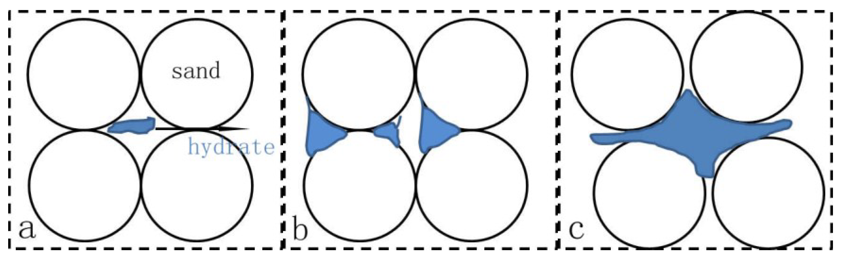
Waite [23] reported that the effects of hydrate on the host sediment properties were closely related to where the hydrate forms in the pore space. The three most common hydrate habits are pore filling, load bearing, and cementation. Figure 6 shows a sketch of different hydrate habits. Pore-filling hydrate may be naturally transformed into load-bearing hydrate when the hydrate saturation is greater than 25–40% [24,25]. As such, the methane hydrate acts as a skeleton structure at large saturation values. When the depressurization process was performed, the disintegration of methane hydrate resulted in structural instability of high saturation methane hydrate-bearing sediments and the volume decreased tremendously. In contrast, most of the methane hydrate was in the pore space as pore-filling or cementation when saturation was low. The change in volume was more obvious for the high saturation sample. Zhang et al. [26] reported that the shear strengths reduce more for a higher initial gas hydrate saturation due to the stronger structural change, breakage of the linkage and cementation between gas hydrate and soil grains.
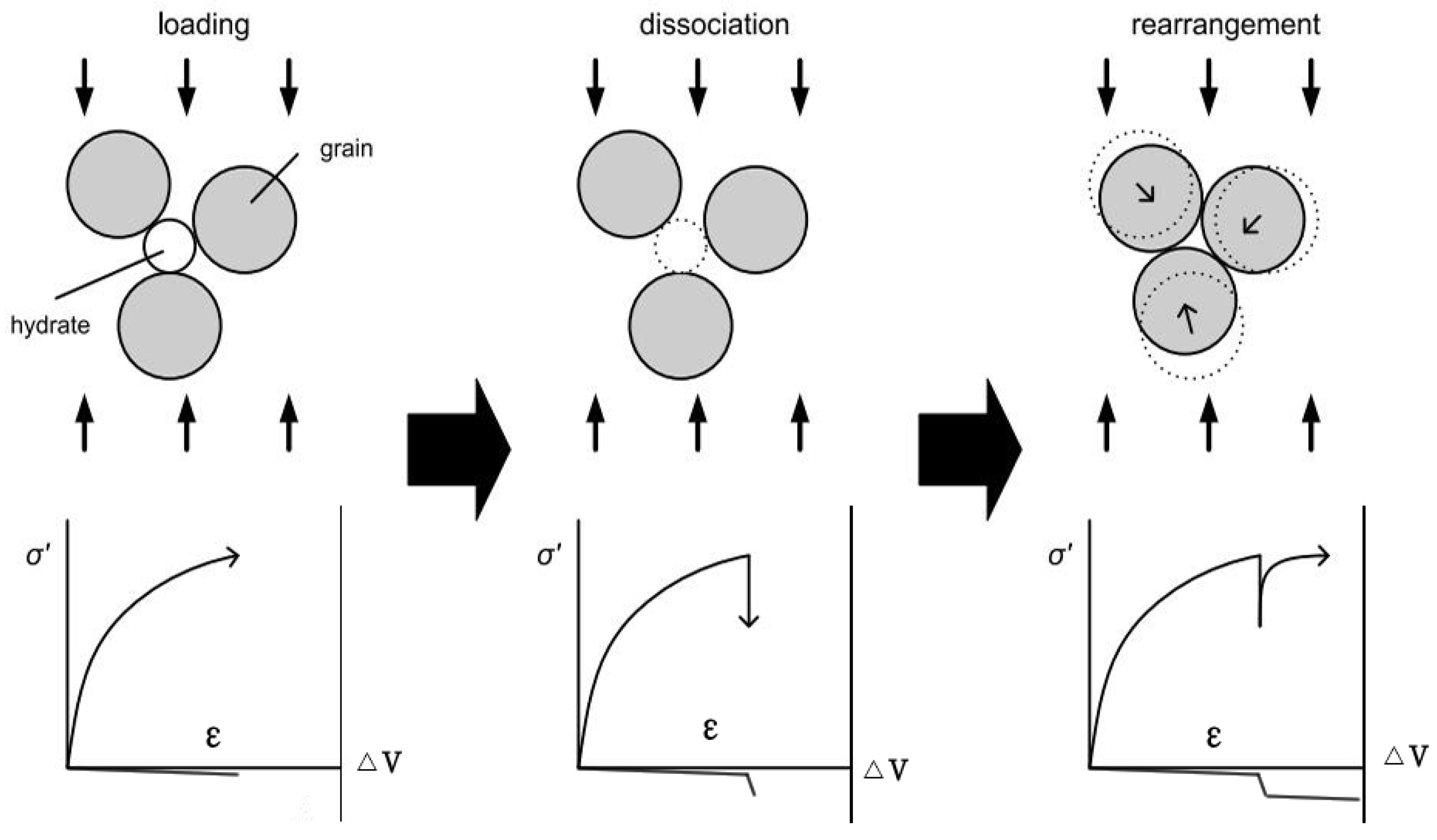
Figure 7 shows a schematic diagram of the mechanical influences of hydrate decomposition in the sediments. When additional effective stresses are applied such as by wellbore drilling or sedimentation, both the hydrate and sediment skeleton are loaded. In this case, the deviator stress of the sample will increase with the axial strain. When the hydrate dissociates, the overall effective stresses decrease under zero straining condition and the sediment particles are unstable. This is followed by an instant deformation to recover the reduced effective stresses. The deviator stress exhibits a decreasing trend for a short period of time. After the sediment particles are repressed and rearranged, the deviator stress increases again with increasing axial strain and presents a new correlation between the stress and the strain.
3.4. Particle Size of the Sediments after the Shear Tests
Figure 8 shows the particle size distributions of sediments before and after the shear tests and Table 2 shows the median diameters after the shear tests. The median diameter of these specimens was 0.1122 ± 0.0022 mm before the shear tests. The median diameter of the particle size of sediments after the shear tests decreased with the increase in confining pressure, indicating that particle damage was more obvious. It also implies that when the hydrates dissociated, sediment particles might be rearranged and broken under high confining pressure, which could lead to a decrease in permeability or increase in the amount of sand production. This may also explain that under high effective confining pressure, the volume of the sample shrinks more significantly.
4. Conclusions
- (1)
- During the shear process, pore pressure decreases may result in the failure of the hydrate-bearing specimen, but it did not collapse completely due to the high effective confining pressure.
- (2)
- The contraction tendency of volumetric strain was observed during depressurization and the ultimate deformation showed no difference from prior to depressurization.
- (3)
- The degree of stress reduction was greater during depressurization for the high saturation hydrate-bearing sediments. This could be because the methane hydrate acted as a skeleton structure when the pore hydrate saturation is large.
Author Contributions
D.-L.L., D.-Q.L. and X.-S.L. conceived and designed the experiments; Q.W., Z.W. and J.L. performed the experiments; D.-L.L. and Q.W. analyzed the data and wrote the paper.
Acknowledgments
The work was supported by the National Key Research & Development Plan of China (No. 2017YFC0307305), the National Natural Science Foundation of China (51474197, 51661165011), Key Program of National Natural Science Foundation of China (51736009) and Natural Science Foundation of Guangdong Province (No. 2015A030310422).
Conflicts of Interest
There are no conflicts to declare.
References
- Kvenvolden, K.A. Methane hydrate—A major reservoir of carbon in the shallow geosphere? Chem. Geol. 1988, 71, 41–51. [Google Scholar] [CrossRef]
- Lee, S.Y.; Holder, G.D. Methane hydrates potential as a future energy source. Fuel Process. Technol. 2001, 71, 181–186. [Google Scholar] [CrossRef]
- Chong, Z.R.; Yang, S.H.B.; Babu, P.; Linga, P.; Li, X.-S. Review of natural gas hydrates as an energy resource: Prospects and challenges. Appl. Energy 2016, 162, 1633–1652. [Google Scholar] [CrossRef]
- Durham, W.B.; Kirby, S.H.; Stern, L.A.; Zhang, W. The strength and rheology of methane clathrate hydrate. J. Geophys. Res. Solid Earth 2003, 108. [Google Scholar] [CrossRef] [Green Version]
- Yun, T.S.; Narsilio, G.A.; Santamarina, J.C.; Ruppel, C. Instrumented pressure testing chamber for characterizing sediment cores recovered at in situ hydrostatic pressure. Mar. Geol. 2006, 229, 285–293. [Google Scholar] [CrossRef]
- Masui, A.; Miyazaki, K.; Haneda, H.; Ogata, Y.; Aoki, K. Mechanical Properties of Natural Gas Hydrate Bearing Sediments Retrieved from Eastern Nankai Trough. In Proceedings of the Offshore Technology Conference, Houston, Texas, USA, 5–8 May 2008. [Google Scholar]
- Hyodo, M.; Nakata, Y.; Yoshimoto, N.; Orense, R.; ISOPE. Shear behaviour of methane hydrate-bearing sand. In Proceedings of the Seventeenth International Offshore and Polar Engineering Conference, Lisbon, Portugal, 1–6 July 2007. [Google Scholar]
- Yoneda, J.; Hyodo, M.; Yoshimoto, N.; Nakata, Y.; Kato, A. Development of high-pressure low-temperature plane strain testing apparatus for methane hydrate-bearing sand. Soils Found. 2013, 53, 774–783. [Google Scholar] [CrossRef]
- Yun, T.S.; Santamarina, J.C.; Ruppel, C. Mechanical properties of sand, silt, and clay containing tetrahydrofuran hydrate. J. Geophys. Res.-Solid Earth 2007, 112. [Google Scholar] [CrossRef] [Green Version]
- Hyodo, M.; Nakata, Y.; Yoshimoto, N.; Yoneda, J. Shear strength of methane hydrate bearing sand and its deformation during dissociation of methane hydrate. Deform. Charact. Geomater. 2008, 1–2, 549–556. [Google Scholar]
- Luo, T.; Song, Y.; Zhu, Y.; Liu, W.; Liu, Y.; Li, Y.; Wu, Z. Triaxial experiments on the mechanical properties of hydrate-bearing marine sediments of South China Sea. Mar. Petrol. Geol. 2016, 77, 507–514. [Google Scholar] [CrossRef]
- Li, Y.H.; Song, Y.C.; Liu, W.G.; Yu, F. Experimental Research on the Mechanical Properties of Methane Hydrate-Ice Mixtures. Energies 2012, 5, 181–192. [Google Scholar] [CrossRef] [Green Version]
- Aoki, K.; Masui, A.; Haneda, H.; Ogata, Y. Compaction behavior of Toyoura sand during methane hydrate dissociation. In Proceedings of the Seventh ISOPE Ocean Mining Symposium, Lisbon, Portugal, 1–6 July 2007. [Google Scholar]
- Hyodo, M.; Li, Y.H.; Yoneda, J.; Nakata, Y.; Yoshimoto, N.; Nishimura, A. Effects of dissociation on the shear strength and deformation behavior of methane hydrate-bearing sediments. Mar. Petrol. Geol. 2014, 51, 52–62. [Google Scholar] [CrossRef]
- Priest, J.A.; Rees, E.V.L.; Clayton, C.R.I. Influence of gas hydrate morphology on the seismic velocities of sands. J. Geophys. Res. Solid Earth 2009, 114. [Google Scholar] [CrossRef] [Green Version]
- Miyazaki, K.; Masui, A.; Sakamoto, Y.; Aoki, K.; Tenma, N.; Yamaguchi, T. Triaxial compressive properties of artificial methane-hydrate-bearing sediment. J. Geophys. Res. Solid Earth 2012, 116. [Google Scholar] [CrossRef]
- Dai, S.; Seol, Y. Impacts of Hydrate Distribution on the Hydro-Thermo-Mechanical Properties of Hydrate-Bearing Sediments; AGU Fall Meeting Abstracts; AGU: Washington, DC, USA, 2015. [Google Scholar]
- Kimoto, S.; Oka, F.; Fushita, T.; Fujiwaki, M. A chemo-thermo-mechanically coupled numerical simulation of the subsurface ground deformations due to methane hydrate dissociation. Comput. Geotech. 2007, 34, 216–228. [Google Scholar] [CrossRef]
- Rutqvist, J.; Moridis, G.J.; Grover, T.; Collett, T. Geomechanical response of permafrost-associated hydrate deposits to depressurization-induced gas production. J. Petrol. Sci. Eng. 2009, 67, 1–12. [Google Scholar] [CrossRef] [Green Version]
- Ghiassian, H.; Grozic, J.L.H. Strength behavior of methane hydrate bearing sand in undrained triaxial testing. Mar. Petrol. Geol. 2013, 43, 310–319. [Google Scholar] [CrossRef]
- Hyodo, M.; Yoneda, J.; Yoshimoto, N.; Nakata, Y. Mechanical and dissociation properties of methane hydrate-bearing sand in deep seabed. Soils Found. 2013, 53, 299–314. [Google Scholar] [CrossRef]
- Yan, C.; Cheng, Y.; Li, M.; Han, Z.; Zhang, H.; Li, Q.; Teng, F.; Ding, J. Mechanical experiments and constitutive model of natural gas hydrate reservoirs. Int. J. Hydrogen Energy 2017, 42, 19810–19818. [Google Scholar] [CrossRef]
- Waite, W.F.; Santamarina, J.C.; Cortes, D.D.; Dugan, B.; Espinoza, D.N.; Germaine, J.; Jang, J.; Jung, J.W.; Kneafsey, T.J.; Shin, H. Physical properties of hydrate-bearing sediments. Rev. Geophys. 2009, 47, 465–484. [Google Scholar] [CrossRef]
- Berge, L.I.; Jacobsen, K.A.; Solstad, A. Measured acoustic wave velocities of R11 (CCl 3 F) hydrate samples with and without sand as a function of hydrate concentration. J. Geophys. Res. Solid Earth 1999, 104, 15415–15424. [Google Scholar] [CrossRef]
- Yun, T.S.; Francisca, F.M.; Santamarina, J.C.; Ruppel, C. Compressional and shear wave velocities in uncemented sediment containing gas hydrate. Geophys. Res. Lett. 2005, 32, 153–174. [Google Scholar] [CrossRef]
- Zhang, X.H.; Luo, D.S.; Lu, X.B.; Liu, L.L.; Liu, C.L. Mechanical properties of gas hydrate-bearing sediments during hydrate dissociation. Acta Mech. Sin. 2018, 34, 266–274. [Google Scholar] [CrossRef]
- Shun, U. Numerical Investigation of Geomechanical Behaviour of Hydrate-Bearing Sediments. Ph.D. Thesis, University of Cambridge, Cambridge, UK, 2013. [Google Scholar]
Figure 1.
Schematic diagram of the tri-axial shear testing apparatus. (1) computer; (2) data acquisition system; (3) buffer tank; (4) methane gas bottle; (5) water pump; (6) thermal control pump; (7) stress transducer; (8) temperature sensor; (9) displacement transducer; (10) specimen; (11) syringe pump; (12) gas-liquid separator; (13) desiccant; (14) vacuum pump.

Figure 2.
The grain size (mm) distributions of the host sand.
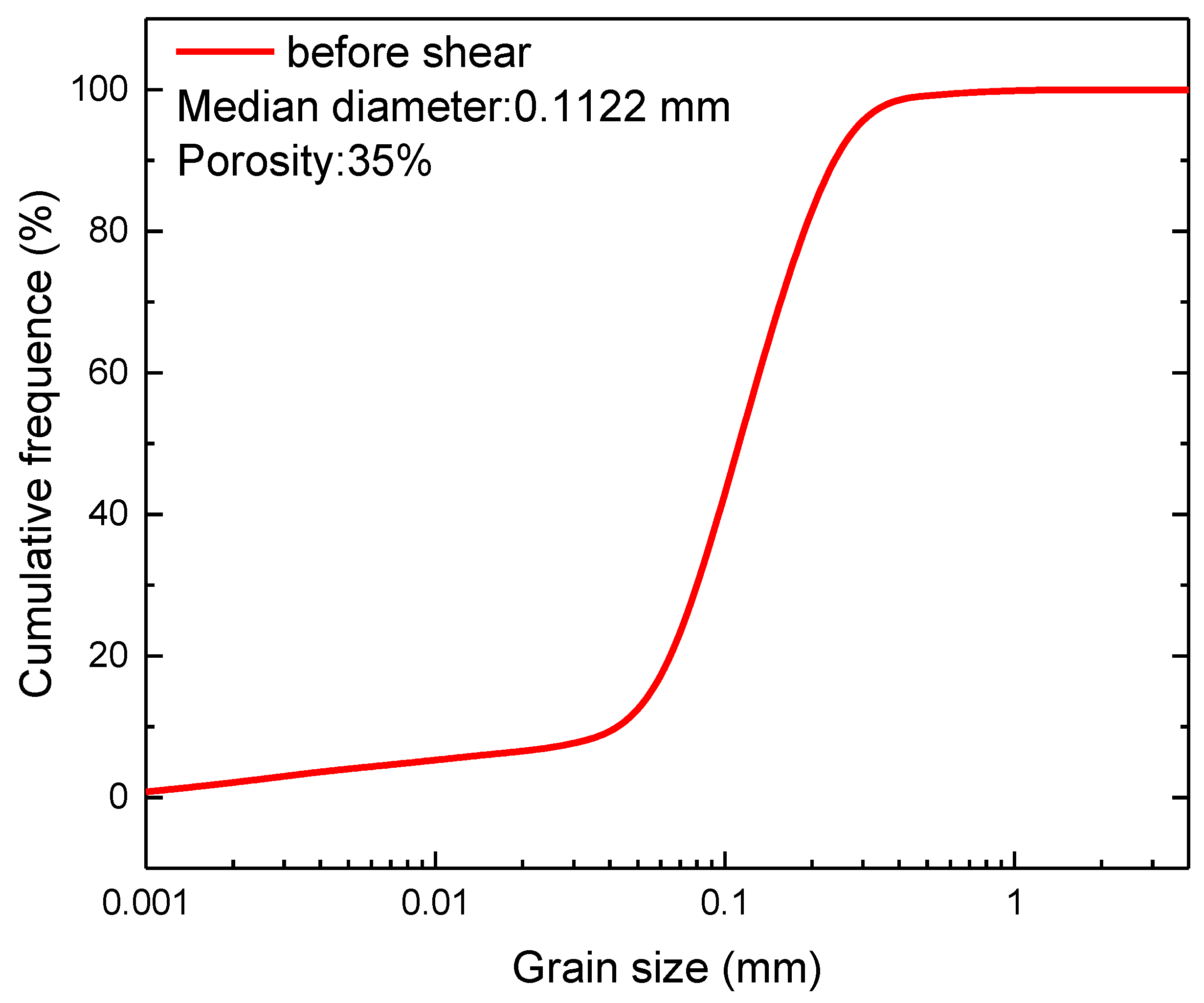
Figure 3.
Relationships of deviator stress, volumetric strain, pore pressure, and methane hydrate saturation to axial strain of methane hydrate-bearing sediments dissociated by the depressurization method.
Figure 3.
Relationships of deviator stress, volumetric strain, pore pressure, and methane hydrate saturation to axial strain of methane hydrate-bearing sediments dissociated by the depressurization method.

Figure 4.
Deviator stress, volumetric strain, pore pressure, hydrate saturation and axial strain tendencies of the various specimen under different shear conditions.
Figure 4.
Deviator stress, volumetric strain, pore pressure, hydrate saturation and axial strain tendencies of the various specimen under different shear conditions.

Figure 5.
Deviator stress, volumetric strain, pore pressure, and axial strain relationships of specimens with various saturation levels.
Figure 5.
Deviator stress, volumetric strain, pore pressure, and axial strain relationships of specimens with various saturation levels.

Figure 6.
Schematic diagram of different type of hydrate habits. (a) pore filling; (b) cementation; (c) load bearing.
Figure 6.
Schematic diagram of different type of hydrate habits. (a) pore filling; (b) cementation; (c) load bearing.

Figure 7.
Schematic diagram of the mechanical influence of hydrate decomposition in the sediments (modified from Uchida S [27]).
Figure 7.
Schematic diagram of the mechanical influence of hydrate decomposition in the sediments (modified from Uchida S [27]).

Figure 8.
Particle size distributions of sediments before and after shear.


Table 1.
Experimental parameters and shear conditions.
| Test Name | Temperature (K) | Confining Pressure (MPa) | Pore Pressure (MPa) | Saturation (%) | Remarks |
|---|---|---|---|---|---|
| P1 | 279.15 | 10 | 8 | 0 | Partially water saturated sand |
| P2 | 279.15 | 12 | 10 | 0 | Partially water saturated sand |
| P3 | 279.15 | 14 | 12 | 0 | Partially water saturated sand |
| P4 | 279.15 | 10 | 3 | 0 | Water saturated sand |
| P5 | 279.15 | 12 | 3 | 0 | Water saturated sand |
| M0 | 279.15 | 12 | 10 | 35.23 | Shear without dissociation |
| M1 | 279.15 | 10 | 8→3 | 38.05 | Shear 2.5%→shear under dissociation |
| M2 | 279.15 | 12 | 10→3 | 33.82 | Shear 0.5%→shear under dissociation |
| M3 | 279.15 | 12 | 10→3 | 33.82 | Shear 1.0%→shear under dissociation |
| M4 | 279.15 | 12 | 10→3 | 37.48 | Shear 2.5%→shear under dissociation |
| M5 | 279.15 | 12 | 10→3 | 56.14 | Shear 2.5%→shear under dissociation |
| M6 | 279.15 | 14 | 12→3 | 37.58 | Shear 2.5%→shear under dissociation |
Table 2.
Median size of the specimens after the shear tests.
| Specimens | Test Condition | Median Diameter (mm) | Variation (mm) | |
|---|---|---|---|---|
| Confining Pressure (MPa) | Pore Pressure (MPa) | |||
| P1 | 10 | 8 | 0.1107 | −0.0014 |
| P2 | 12 | 10 | 0.1087 | −0.0034 |
| P3 | 14 | 12 | 0.0969 | −0.0152 |
| M1 | 10 | 8→3 | 0.1112 | −0.0009 |
| M4 | 12 | 10→3 | 0.1040 | −0.0081 |
| M6 | 14 | 12→3 | 0.0965 | −0.0156 |
© 2018 by the authors. Licensee MDPI, Basel, Switzerland. This article is an open access article distributed under the terms and conditions of the Creative Commons Attribution (CC BY) license (http://creativecommons.org/licenses/by/4.0/).
Share and Cite
MDPI and ACS Style
Li, D.; Wu, Q.; Wang, Z.; Lu, J.; Liang, D.; Li, X. Tri-Axial Shear Tests on Hydrate-Bearing Sediments during Hydrate Dissociation with Depressurization. Energies 2018, 11, 1819. https://doi.org/10.3390/en11071819
AMA Style
Li D, Wu Q, Wang Z, Lu J, Liang D, Li X. Tri-Axial Shear Tests on Hydrate-Bearing Sediments during Hydrate Dissociation with Depressurization. Energies. 2018; 11(7):1819. https://doi.org/10.3390/en11071819
Chicago/Turabian StyleLi, Dongliang, Qi Wu, Zhe Wang, Jingsheng Lu, Deqing Liang, and Xiaosen Li. 2018. "Tri-Axial Shear Tests on Hydrate-Bearing Sediments during Hydrate Dissociation with Depressurization" Energies 11, no. 7: 1819. https://doi.org/10.3390/en11071819
Note that from the first issue of 2016, this journal uses article numbers instead of page numbers. See further details here.