Novel Sparse-Coded Ambient Backscatter Communication for Massive IoT Connectivity


School of Information and Communication Engineering, Sungkyunkwan University, Suwon 440-746, Korea
*
Author to whom correspondence should be addressed.
Energies 2018, 11(7), 1780; https://doi.org/10.3390/en11071780
Submission received: 8 June 2018
/
Revised: 30 June 2018
/
Accepted: 5 July 2018
/
Published: 6 July 2018
Abstract
:Low-power ambient backscatter communication (AmBC) relying on radio-frequency (RF) energy harvesting is an energy-efficient solution for batteryless Internet of Things (IoT). However, ambient backscatter signals are severely faded by dyadic backscatter channel (DBC), limiting connectivity in conventional orthogonal time-division-based AmBC (TD-AmBC). In order to support massive connectivity in AmBC, we propose sparse-coded AmBC (SC-AmBC) based on non-orthogonal signaling. Sparse code utilizes inherent sparsity of AmBC where power supplies of RF tags rely on ambient RF energy harvesting. Consequently, sparse-coded backscatter modulation algorithm (SC-BMA) can enable non-orthogonal multiple access (NOMA) as well as M-ary modulation for concurrent backscatter transmissions, providing additional diversity gain. These sparse codewords from multiple tags can be efficiently detected at access point (AP) using iterative message passing algorithm (MPA). To overcome DBC along with intersymbol interference (ISI), we propose dyadic channel estimation algorithm (D-CEA) and dyadic MPA (D-MPA) exploiting weighted-sum of the ISI for information exchange in the factor graph. Simulation results validate the potential of the SC-AmBC in terms of connectivity, detection performance and sum throughput.
1. Introduction
1.1. Backgrounds
Massive connectivity is a key component of future Internet of things (IoT) where radio frequency (RF) devices continuously interact with humans’ daily routine. The vision includes smart home gadgets connected to Wi-Fi (Wireless Fidelity) [1,2], real-time interactive applications such as Bluetooth exchanging video/audio data with a smart phone [3], and inventory management in a huge warehouse [4]. In these applications, RF devices should be designed in low power for prolonging their lifetime and small-form factor for cost savings. Unfortunately, it is reported that most of the power in RF devices are consumed by oscillators, which generate sinusoidal carrier signals for modulation of data. The high power consumption for this digital-to-analog converter (DAC) hinders connectivity for numerous IoT applications with energy-constrained RF devices [5,6,7]. Hence, alternative modulation without the oscillator is considered to be a promising solution for fulfilling IoT requirements.
Ambient backscatter communication (AmBC) is an innovative solution for batteryless IoT, since it replaces power-hungry oscillator with passive load impedances connected to RF antenna [5,6,7]. RF tags, kinds of RF devices composed of low-power micro-controller and load impedances, can reuse ambient signals such as television (TV) [5,7] and Wi-Fi [1,2,6] for sending their data. Instead of generating RF sinusoidal signals, RF tags simply reflect incoming ambient signals and modulate their data by switching load impedances. These load impedances implemented by passive circuit components, resistors and capacitors can constitute two-dimensional signal constellation space spanned by real and imaginary axes of reflection coefficients [8,9]. Only a few of power is required for AmBC, which is in sharp contrast to traditional active RF radios demanding few tens of . In addition, ultra-low power consumption of backscatter tags can sustain with ambient RF energy harvesting (EH). Ambient RF signals can be recycled not only for EH but also for information transmission over RF signals by controlling reflection coefficients at RF tags. Therefore, AmBC has strong advantages in terms of energy efficiency and installation cost by reducing the size of RF hardware.
1.2. Related Works
Despite of its benefits, AmBC has several challenges that originate from inherent characteristics of RF signals and channels. Firstly, the ambient signals are not dedicated to backscatter communications. Hence, some of the backscatter schemes based on unmodulated excitation signals, such as energy beamforming [10,11], space-time coding [12,13], and frequency up/down conversion in radio-frequency identification (RFID) [3,4], may not be available in AmBC. Without dedicated RF infrastructure (i.e., 915 MHz RFID reader and power beacon), previous works such as LoRa (Long Range) [14], rateless code [15], statistical inference [16], time-hopping spreading spectrum [17] are not directly applied to AmBC scenarios. Since low-rate symbols are modulated on high-rate ambient signals, modulations and detections should be redesigned for applications of AmBC. Second, channel propagation of AmBC is distinguished from that of active radios [12,13,18,19,20,21]. Compared to one-way channel between transmitter and receiver [22], backscatter radios experience two-way channels (Here, we assume monostatic ambient backscatter where the reader (e.g., Wi-Fi AP) generates RF signals intended for legacy (Wi-Fi) users (instead of RF tags) and also acts as the receiver for the signals reflected from RF tags [2,23]. On the other hand, there is bistatic ambient backscatter where the RF signals are generated from the separated TV or FM station, and cellular base station, while the reader received the reflected signals from RF tags [5,7]): forward channel from reader to tag; backward channel from tag to reader. The cascade of two channels is referred to as dyadic backscatter channel (DBC) and exhibits significant channel attenuations [18] as well as delay spreads [23] compared to the one-way channel. Eventually, the phenomena lead to a low signal-to-noise ratio (SNR) for detection and severe intersymbol interference (ISI).
To overcome the inherent limitations in AmBC, various modulation and detection techniques based on diversity combining schemes are proposed. Multiple receive antennas can enhance detection performance in AmBC. For example, interference cancellation schemes using channel differences [7], or zero-forcing [24] are proposed. The multi-antenna configurations are useful for achieving spatial diversity gain and effective as the number of receive antennas increases. On the other hand, modulation and detection based on spreading sequences can also improve reliability achieving temporal diversity gain. In [2,5], detection SNR of AmBC is reinforced using maximal-ratio combining of backscatter samples. In [25], periodicity of ambient signal is utilized using cyclic prefix (CP) in orthogonal frequency division multiplexing (OFDM) sequences. Orthogonal spreading structure similar to code-division multiple access (CDMA) is proposed in [7].
However, most of the AmBC assumed orthogonality in both modulations and detections. For instance, non-overlapping backscatter symbols are typically represented in two-dimensional Euclidean space (e.g., on-off keying (OOK) [5,6], phase-shift keying (PSK) [2], ternary encoding [26] with orthogonal multiple access (OMA) such as time-division multiple access (TDMA) [27] for providing connectivity). For detections, conventional AmBC ignored ISI in DBC by assuming a long period of backscatter symbol [23] or simply filtered it, which reduces SNR for signal detections [2,23]. In AmBC, tag backscatters data in active mode and harvests RF energy in idle mode whose time portion is much larger than the active mode [15]. Consequently, we can utilize the duty-cycling operation by employing sparse coding over ambient RF signals and support non-orthogonal multiple access (NOMA) for massive connectivity. In addition, low-rate backscatter data are delivered over high-rate ambient RF signal, which can be equivalently regarded as spreading sequences to provide diversity gain for reliable backscatter communications [25]. Utilizing the non-orthogonality for large-scale multiple access [28], high-rate modulation [29], and cooperative diversity [30] techniques attracted significant attention in the fifth generation (5G) wireless network. Non-orthogonal signaling can support various wireless applications such as massive machine type communications (mMTC), ultra-reliable and low-latency communications (URLLC), and simultaneous wireless information and power transfer (SWIPT). However, there is a significant gap between NOMA and AmBC techniques, which requires sophisticated design criteria rather than a simple combination of existing RF techniques.
- Modulation and Coding Scheme (MCS): In AmBC, MCS is implemented by only passive RF components with limited circuit power. Advanced MCS such as an adapting power ratio in conventional power-domain NOMA, or infinite-length channel coding may not be available in low-complexity AmBC hardware. Hence, code-domain NOMA based on sparse coding is preferred to power-domain NOMA especially for AmBC applications [28,29].
- Channel and Detector Modeling: Generally, AmBC modulation is operated in time domain typically using OOK [5,6] and M-PSK [2]. NOMA modulation, on the other hand, is operated in frequency domain such as filtered OFDM [31] for mitigating multipath fading. Consequently, AmBC signal is severely distorted by ISI as a tag’s information is conveyed in a high-rate ambient RF signal and experiences a two-way fading channel in time domain. Thus, proper channel and detector modeling are necessary in AmBC to prevent performance degradation, which may be induced by application of NOMA.
Therefore, we propose non-orthogonal sparse coding and a detector to realize massive connectivity for AmBC, which bridges the significant gap between AmBC and NOMA.
1.3. Proposed Sparse-Coded AmBC (SC-AmBC)
On the other hand, non-orthogonal signaling in both modulation and detection is proposed recently. For example, sparse code multiple access (SCMA) proposed by Huawei (China) proved effective in a highly-overloaded network [32,33]. In particular, sparse coding has three desirable properties that are suitable for massive connectivity:
- Grant-Free Uplink Transmission: With sparse coding, RF tags can transmit data in the uplink based on a predefined sparse codebook. The codebook structure can accommodate massive and bursty uplink traffic without a request-grant procedure [34]. The property can lead to low-latency without scheduling and resource allocation in contrast to the cognitive radio based AmBC [27].
- NOMA: Sparse code encodes data in multi-dimensional complex codewords providing higher degrees of freedom than conventional two-dimensional AmBC modulators [2,5,6,26]. As a result, sparse code can support concurrent RF transmissions and multiple-access interference (MAI) can be efficiently resolved by an iterative message passing algorithm (MPA) [32].
- Projected M-ary Modulation: In conventional AmBC modulators, M-ary modulation is only implemented by M distinct load impedances increasing form factors of RF devices for higher-order modulations [2,8,9]. On the other hand, with sparse coding, M-ary data can be represented by few constellation symbols using codeword projection/expansion method [35,36]. Thus, M-ary modulation can be realized in AmBC without increasing form factors of RF devices.
In addition, due to increasing network densification and delay spreads in multipath propagation, exploiting ISI can achieve better spectral properties than conventional detectors by removing CP [31]. Based on these observations, we propose sparse-coded AmBC (SC-AmBC) including design of modulators and detectors for DBC. Our main contributions can be summarized as follows:
- Sparse-coded backscatter modulation algorithm (SC-BMA) supporting M-ary modulation for AmBC with small-form factors. The modulation can constitute multi-dimensional signal space, which can be easily implemented for passive RF tags without increasing form-factor and exempted from complex signal processing burdening low-cost RF tags.
- Dyadic channel estimation algorithm (D-CEA) fully capturing characteristics of DBC. The channel modeling includes both the effect of cascaded channel in AmBC and the effect of NOMA signaling and is distinguished from one-way Rayleigh and single-path fading channel without ISI.
- Dyadic MPA (D-MPA) based on dyadic factor graph exploiting the weighted-sum of ISI caused by DBC in information exchange process. The proposed MPA exploiting ISI instead of filtering it provides superior detection performance to traditional MPA designed for one-way channels.
To the best of the authors’ knowledge, implementing the sparse code for energy-constrained AmBC is not fully explored in literature. The rest of the paper is organized as follows. Section 2 describes SC-AmBC and motivating examples of our model therein. Section 3 presents the load modulation including a sparse coding algorithm and channel estimation algorithm, and an iterative detector based on DBC is proposed in Section 4. Simulation results are provided in Section 5. Finally, Section 6 concludes the paper.
2. System Model
2.1. Notation
Matrices (vectors) are denoted with upper (lower) case bold-face letters (e.g., or ); the operator denotes the Hermitian; the operator denotes the vector norm; the operator ⊗ denotes the Kronecker product; the set of real, complex and binary numbers are respectively denoted by , and ; the vector denotes an all-one column vector with size k and the vector denotes an all-zero column vector with size k; the operator denotes the probability of the event . the operator denotes statistical expectation; denotes the circularly symmetric complex normal distribution with mean and variance .
2.2. System Model
We consider the AmBC network [37] based on access point (AP) such as Wi-Fi as depicted in Figure 1. The AP transmits data to its client as well as energy to nearby RF tags [2,8,9,38], replacing expensive and high-power RFID readers. In terms of deployment cost, utilizing ambient signals is very attractive for backscatter communication as they exist everywhere for providing low-cost Internet connectivity (e.g., TV signal, Wi-Fi, BlueTooth). In the AP’s coverage area, there are multiple RF tags utilizing the ambient signals transmitted from the AP to downlink (DL) client. These RF tags can use the ambient signals for RF energy harvesting using a rectifier circuit exempting large-sized batteries. If they harvest sufficient energy for activating backscatter communication, they modulate load impedances connected to micro-controller to transmit M-ary data instead of large and power-intensive oscillator components [2,8,9,38]. Depending on ambient energy harvesting, tags are only activated in a small fraction of time and mostly remain idle against harvest sufficient energy. The sparsity of ambient backscatter signals motivates us to use encoding data for multi-dimensional complex codewords [20,32,33,39] selected by time-variant reflection coefficients [20,40] and enables low-complexity decoding even for a massive number of concurrent RF transmissions and higher-order modulation. Consequently, SC-BMA among RF tags can enable NOMA, while providing massive connectivity for low-cost RF tags.
Upon the tags’ modulation, AP receives low-rate uplink (UL) backscatter signals from the tags while transmitting high-rate DL signals to the client. Assuming a single antenna at AP where transmission and reception occurs simultaneously in full-duplex, these signals are overlapped causing self-interference (SI) [2,41]. In addition, a high-sampling rate of DL signals significantly reduces sampling period of UL backscatter signals, causing ISI in multipath propagation environments [23]. Moreover, non-orthogonality of sparse code may cause MAI among active tags, degrading detection performance of concurrent RF transmissions [32,33,39,42,43,44]. Therefore, the detection of backscatter signals requires mitigation of the three interferences (i.e., SI, ISI and MAI). Based on self-interference cancellation (SIC) [41,45,46], strong DL interference can be efficiently removed so that UL backscatter detection can be feasible in practice [2]. Then, D-CEA followed by low-complexity iterative D-MPA is newly implemented to effectively detect data in the presence of the ISI and MAI. Clearly, the ambient backscatter rather exploiting interferences significantly improves spectral efficiency three-fold: full-duplex [2,41]; NOMA with sparse code [32,33,39]; and multipath-diversity combining [22].
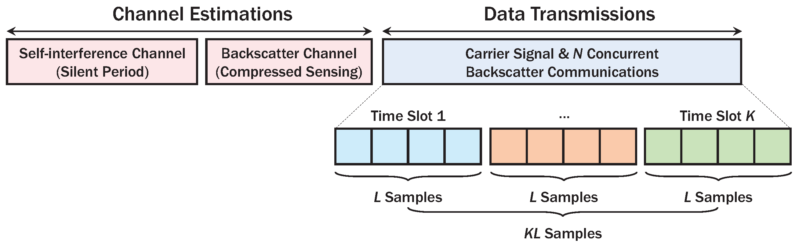
To support multiple RF tags, link layer protocol of AmBC is composed of channel estimation and data transmission phase as described in Figure 2. In the channel estimation phase, AP estimates the SI channel using a silent period for RF tags [2]. Then, the tags transmit sparse pseudo random symbols known to AP, and it can efficiently estimate backscatter channels using compressed sensing algorithms [15,47]. Moreover, as the DBC [12,13,18,19,20,21] experiences two-way fading in contrast to the conventional one-way fading models, D-CEA capturing the characteristics of these channels will be described in Section 3.
In the data transmission phase, an ambient signal from AP can be sliced into K time slots, each with L samples, to spread backscatter signals to increase signal-to-noise ratio (SNR) and reduce circuit-power consumption [2,5,6,7,26,48,49]. As RF tags employ predefined codebooks for data transmissions, active tags can immediately transmit data with low latency without resource allocation and scheduling procedures [34]. At time slot , the ambient signal with average transmit power can be expressed by
where a Gaussian source model with sampling period is assumed to design ambient signal [49]. Next, the signal broadcasted from the AP is attenuated by forward channels. The discrete-time channel impulse response between AP and tag n can be expressed as [23]
where denotes the number of multipath for tag . In Equation (2), , and d, respectively, denote antenna gain at AP, effective aperture of receive antenna and tag distance from AP [40]. Moreover, we assume independent and identically distributed (i.i.d.) channels among tags [12,18,19,21]. It is noteworthy that the forward channel with wide-band ambient signals (e.g., 20 MHz in Wi-Fi) generally experiences frequency-selective fading in sharp contrast to frequency-flat fading in RFID and bistatic backscatter, causing delay spreads of received signals in the forward channel [2]. To capture this characteristic, we can use Toeplitz matrix [50], matrix-vector representations of circular-convolution operations. We define Toeplitz lower- and upper-triangular matrices as follows [23]:
where the matrices and , respectively, denote the Toeplitz forward shift and backward shift matrices of size where the first column of and the first row of are given by and , respectively [23,50]. Due to delay spread, the received signal at tag n at time slot k can be expressed by superposition of k-th signals and -th signals such that
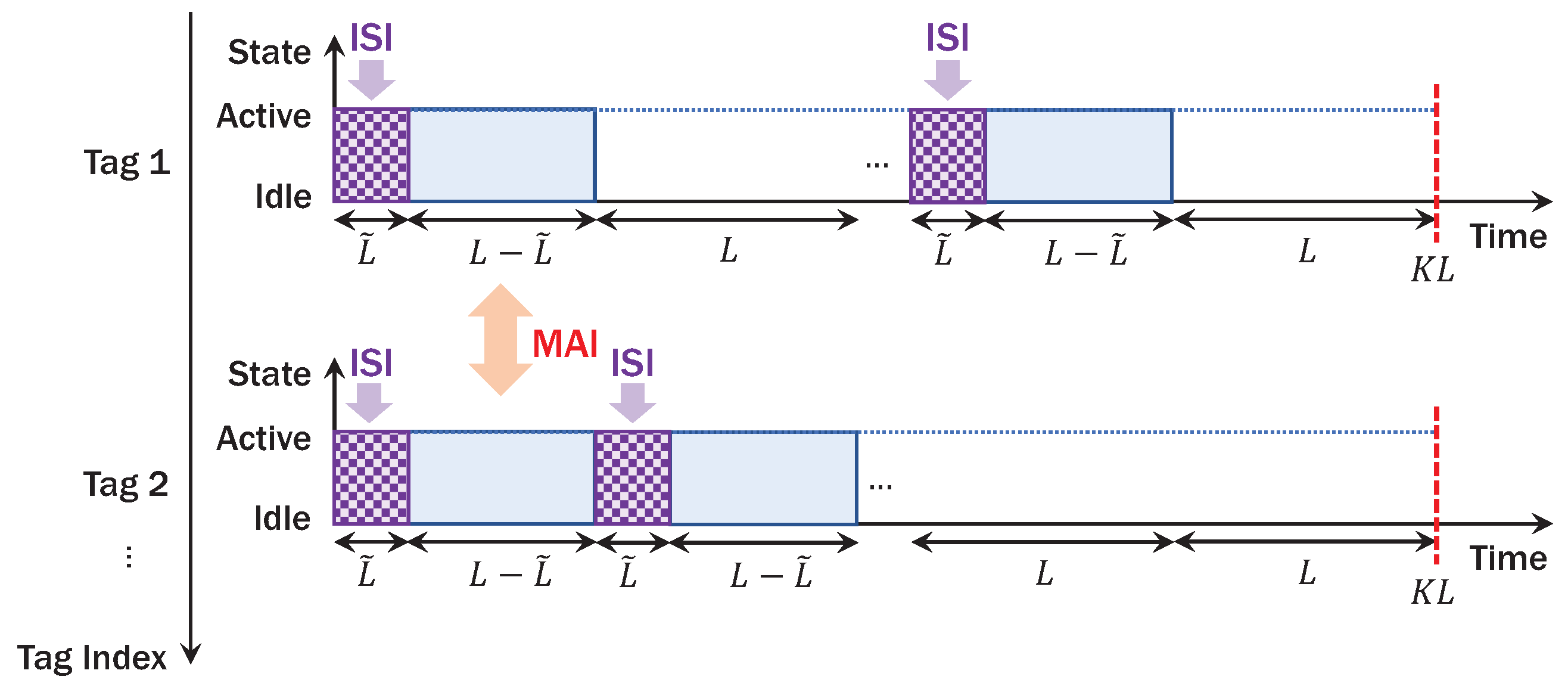
where the second term in Equation (4) constitutes ISI for the ambient signal . Since tags rely on RF energy harvesting, it operates in active or idle state depending on the incident power [37] of the received signal in Equation (4), which is expressed as
As described in Figure 3, the incident power in Equation (5) affects duty-cycling operation and thus sparsity of NOMA. Let be a power ratio between backscattered and incident power, affecting performance of backscatter detection as well as energy harvesting [8,9,38]. Let be the number of time slots when tag is activated. In a codeword of length , each tag is activated for samples and remains idle for . It is remarkable that the delay spread of backscatter channel incurs ISI for samples. Moreover, backscatter symbols from tags (i.e., NOMA) in active states can be interfered in time-domain causing MAI, further complicating reliable detection of AmBC. Since RF tags are powered by ambient energy harvesting, circuit-power constraint that harvested power with efficiency [51] is greater than circuit power for entire sampling period should be satisfied. If we assume a linear power consumption model with respect to energy per symbol and backscatter symbol rate [8,9], the circuit-power constraint can be formulated as
where , and . The average backscatter symbol power proportional to is denoted by and will be discussed in Section 3. For convenient analysis of EH, we define the normalized energy per backscatter symbol as
Under these settings, energy harvesting (EH) constraint or the circuit-power constraint can be reformulated as [37]
From Equation (8), the state of tag (0: idle, 1: active) with EH threshold can be obtained by
where denotes the indicator function of the event x. If the EH constraint is satisfied, tag can encode sparse codewords using simple modulator circuit. In the following sections, we describe AmBC modulator in Section 3 and detector in Section 4.
3. Sparse-Coded Load Modulation
As described in the previous section, we design an AmBC modulator based on load impedances satisfying the following characteristics:
- Small-form Factor: The size of the RF tags is very limited for IoT applications such as implanted biosensors and wearables, so they should have a small number of load impedances to reduce their size. The proposed SC-BMA can enable M-ary modulation [35,36] for these small-form factor IoT devices, which is in sharp contrast to traditional M-ary backscatter modulators with massive number of load impedances (e.g., M-PSK [2], M-QAM [8,52,53]).
- Interference Exploitation: Detection performance of AmBC is severely degraded by the interferences (i.e., MAI and ISI). To rather exploit these interferences for massive connectivity, we design the codeword structure capturing sparsity [39] of ambient EH and characteristics of DBC [18,23] where two-way fading and severe ISI occur.
Toward these goals, we describe the modulation and encoding models [32,33,39,42], which include design of mapping function [35,36] and sparse factor graph [39].
If tag n is activated, the tag generates -length bit stream as follows:
To modulate the binary vector into M-ary backscatter symbol vector , we define the mapping function for and as (Here, we consider relatively small values of and M to show feasibility of high-order AmBC modulation. It is noteworthy that even higher-order modulation (e.g., , ) can be efficiently implemented at RF tag by appropriate design of the parameter set and the mapping function.):
Then, the M-ary symbol vector can be expressed by
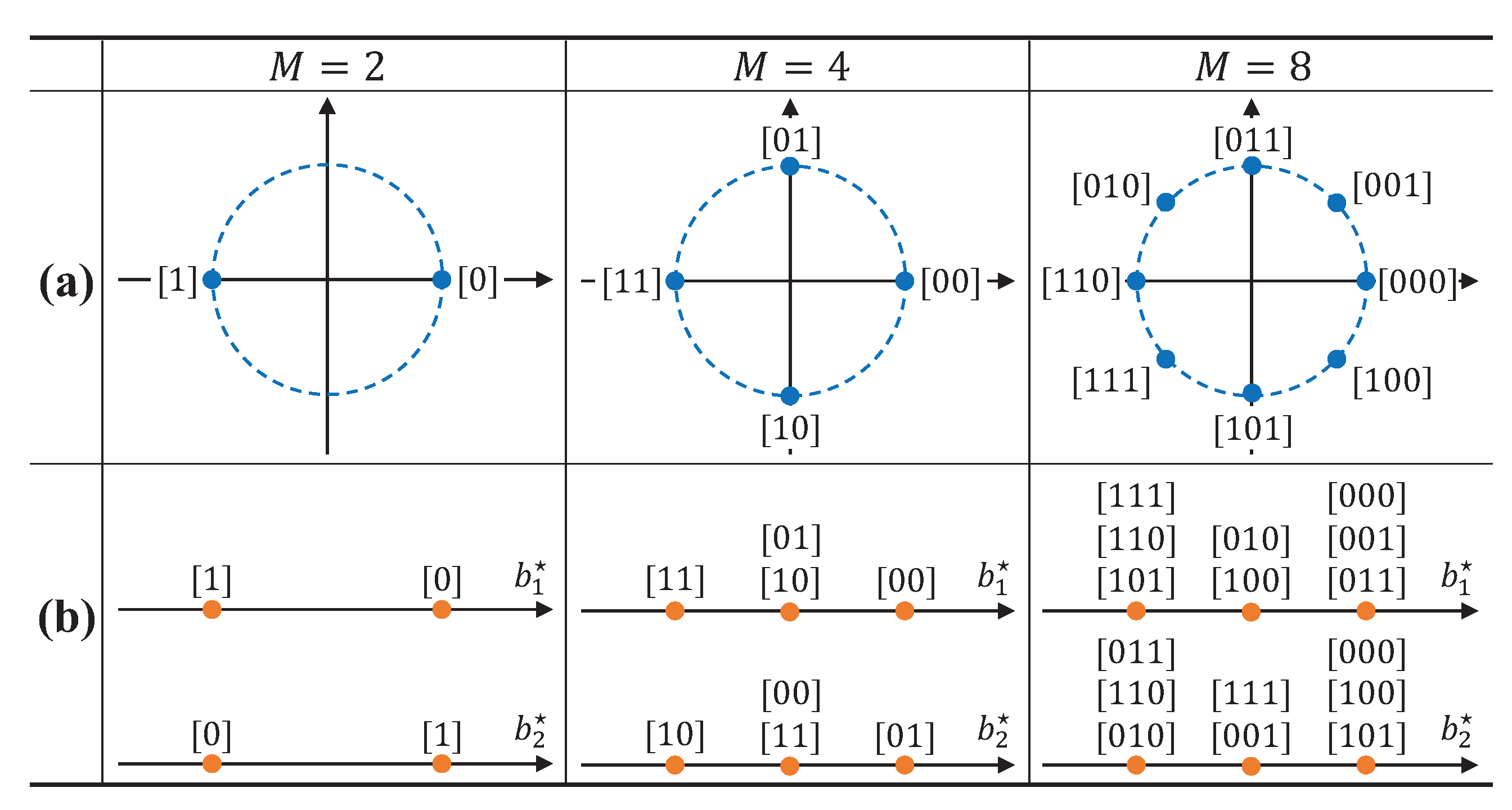
As described in Figure 4, these mapping functions satisfy the small-form factor requirement in RF tags. For instance, in conventional phase-shift keying (PSK)-based backscatter modulator, M constellation points are present in signal constellation with phase difference in Figure 4a [2]. Thus, the modulator requires distinct load impedances, inevitably increasing the size of RF tags. On the other hand, the SC-AmBC modulator only has three constellation points even for higher-order modulation. Accordingly, the required number of load impedances is , since a zero-constellation point is equivalent to the idle state of RF tag [26]. Although several constellation points can be overlapped in Figure 4b, symbols can be detectable as long as they are uniquely mapped in -dimensional signal space in Equation (11), even achieving modulation diversity gain [54] for reliable AmBC. Thus, high-order modulation can be implemented to typical binary PSK (BPSK) backscatter modulator, enabling a high data rate for a small-form factor passive RF devices such as biosensors and wearables.
Remark 1.
The multidimensional mapping function can be designed for any values of and M with the following rules:
- In each dimension, there are three constellation points (i.e., .
- A parameter set satisfies the inequality .
- Multidimensional symbols are mapped with Gray code labeling.
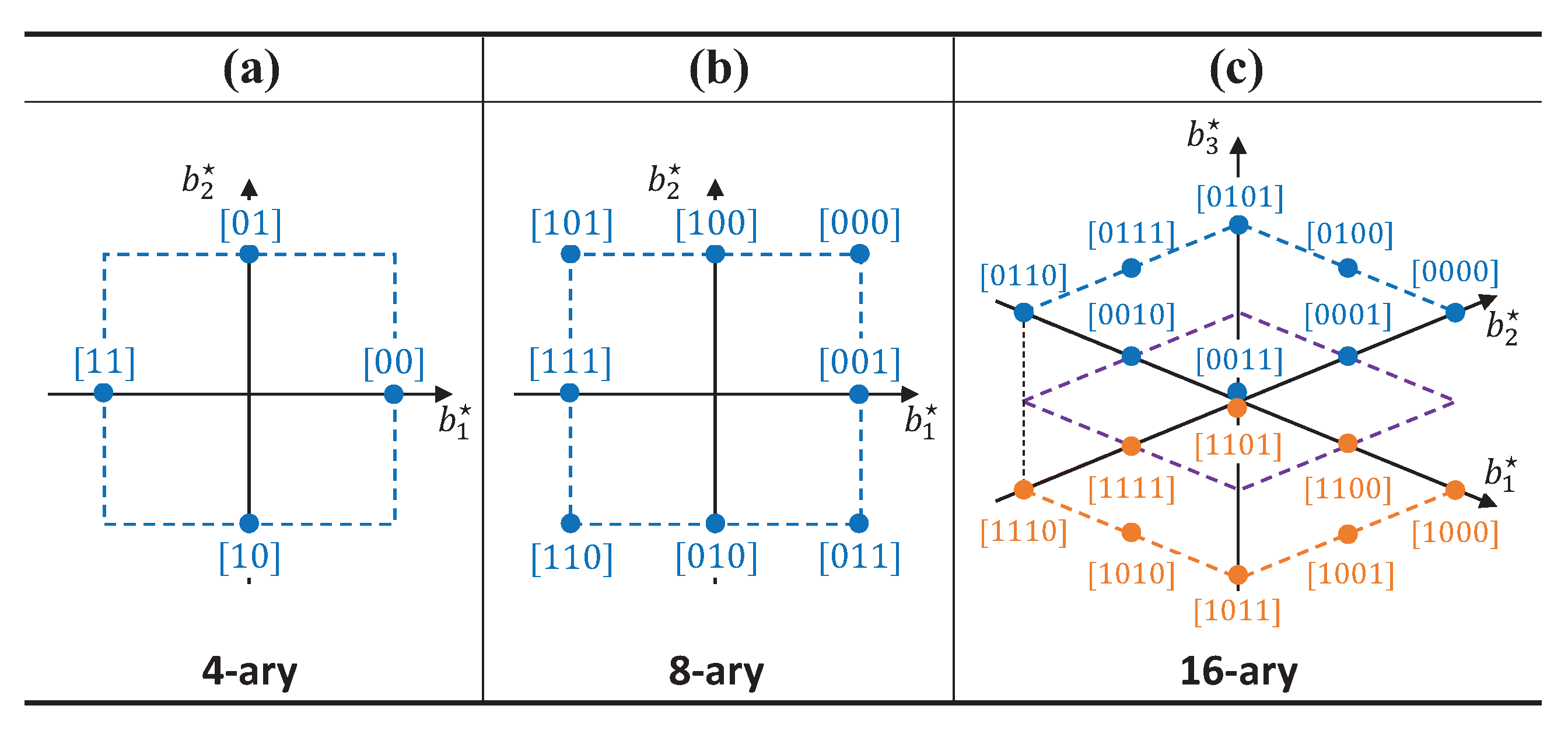
An example of M-ary mapping function in vector space is expressed in Figure 5. Interestingly, the previous example in Figure 4 is the projection of multidimensional symbol to the axes . We can observe that the parameter constitutes the axes of the signal space and M represents the number of constellation points in the vector space. Since the number of symbols RF tag can represent in each dimension is only three, all of the constellation points exist in dashed rectangular lattices in Figure 5 and the number of symbols M is less than for unique mapping of M-ary data. In addition, we adopt lattice constellations along with Gray code labeling to lower bit-error rate (BER), which may be suboptimal but efficient and practical heuristic for solving a mapping function design problem known to be NP-hard (Non-deterministic Polynomial-time hard) [33]. Based on these rules, we can generalize the mapping function even for higher values of and M based on the projection of the multidimensional constellation for the small-form factor AmBC applications. However, due to practical requirements of quality-of-service (QoS) and sparsity issue for low-complexity decoding, we consider small values of and M.
In the sequel, -length modulated symbols are spread into K-length sparse codewords using one-way factor graph (Tanner graph) [44]. By doing so, dimension of signal is extended to -dimension [32,33,39,42] with points in a main constellation, in contrast to conventional AmBC modulators typically laid on two-dimensional Euclidean spaces [22] with M constellation points (e.g., 4-QAM [9,38], 16-QAM [8,52], 16-PSK [2], 32/64-QAM [53]). As a result, the number of tags allowed to transmit is increased to . The overloading factor [32], ratio of the number of RF tags and the time slots can be defined by
In addition, the duty cycle of tag is extended to , which is -fold increase compared to the time-division-based AmBC (TD-AmBC) with [2,27]. Although tags are interfering in an arbitrary time slot, the MAI can be efficiently suppressed by exploiting sparse code structure. Although there are many possible choices of , we choose for simplicity of system modeling. The setting can achieve maximum sparsity as well as reasonable error rate for backscatter detection [39]. In addition, it can reduce complexity of modulation and detection algorithms, which will be discussed later. (For example, if becomes larger, the `for’ loops in Algorithm 1, expressed in terms of and , should be modified in terms of . In addition, information projection and expansion in MPA, as summarized in Table 1, should be extended to higher-order modulation by increasing the range of the indicator parameter as . It is noted that is a common assumption in sparse coding for low-complexity modulation and detection [32,33,34,35,39])
| Algorithm 1 Sparse-coded backscatter modulation algorithm (SC-BMA) | |
| 1: | input the number of time slots K and the modulation order M |
| 2: | obtain the symbol mapping from (11) |
| 3: | fordo |
| 4: | initialize |
| 5: | for do |
| 6: | for do |
| 7: | for do |
| 8: | if then |
| 9: | ▹ first non-zero element |
| 10: | else if then |
| 11: | ▹ second non-zero element |
| 12: | else |
| 13: | ▹ zero element |
| 14: | end if |
| 15: | end for |
| 16: | |
| 17: | end for |
| 18: | end for |
| 19: | end for |
| 20: | obtain , ▹ one-way factor graph, codebook |
| 21: | generate , |
| 22: | generate , |
| 23: | output the codebooks and the factor graphs |
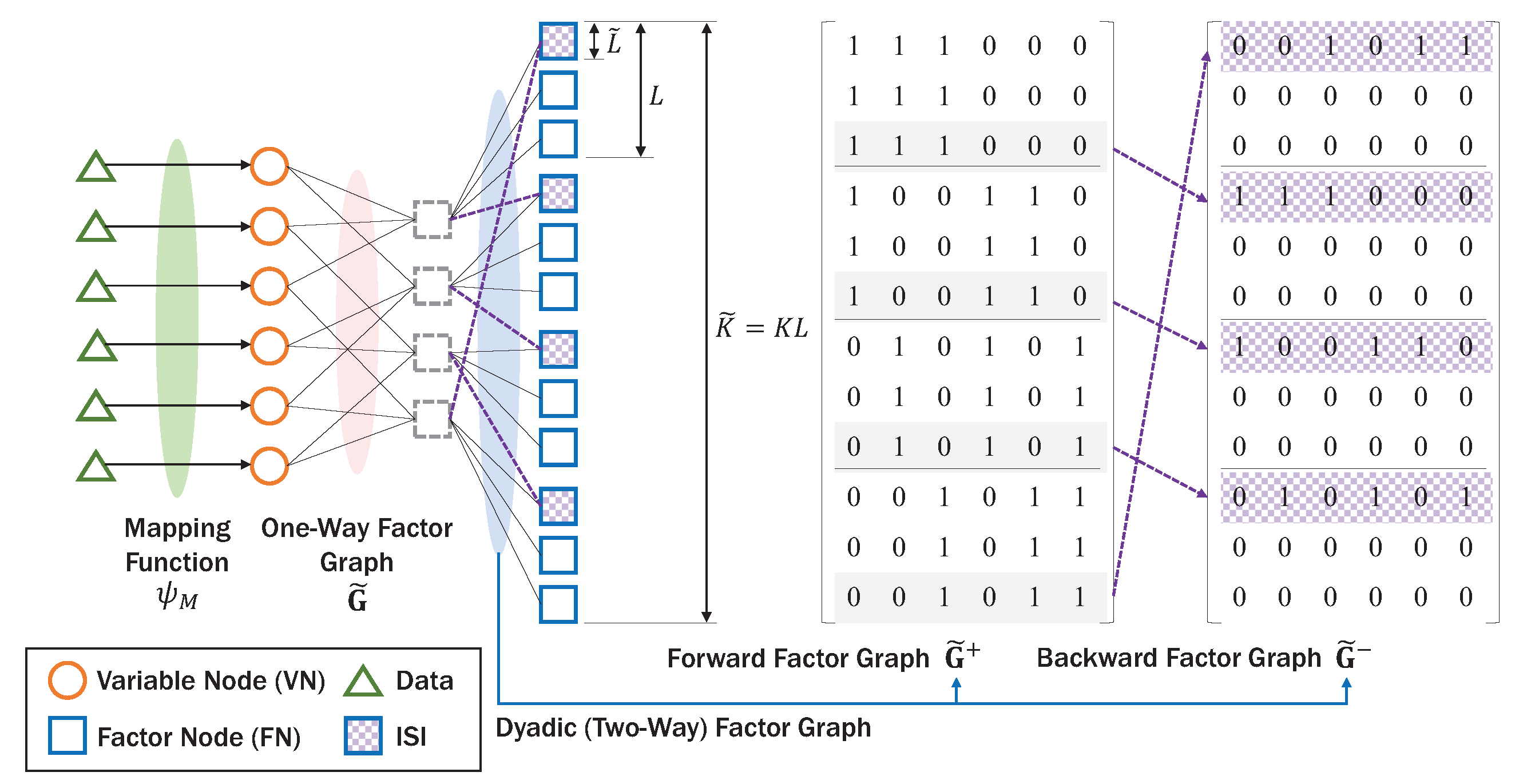
Note that, in AmBC, to conserve energy as well as increase SNR for RF tags, K-length codewords are spanned on L samples, generating -length codewords. In addition, ambient backscatter signal experiences DBC in contrast to the one-way Rayleigh channel in conventional sparse coding. Based on these observations, we introduce dyadic factor graph extending one-way factor graph as shown in Figure 6. The dyadic (two-way) factor graph has two kinds of nodes, namely, variable node (VN) representing codeword of tag and function node (FN) representing received signal at sample . Due to ISI among backscatter signals, the dyadic factor graph is composed of the forward factor graph and the backward factor graph representing interference symbols. Here, we use the superscript to represent the signals related to ISI and the superscript vice versa. The backward factor graph has non-zero rows which are circular-shifted from the forward factor graph, and sparse matrix under the condition , stating that symbols are only interfered by neighboring symbols [23]. The new graph structure can efficiently exploit the MAI and ISI for backscatter detection, satisfying the second requirement of AmBC for massive connectivity. Based on sparse factor graph structure [39] in UL, the backscatter modulation can be generalized by the pseudo codes in Algorithm 1.
Since channel information is not available at RF tags, they encode data using the one-way codebook without knowing ISI, and the forward and backward codebooks containing information on ISI will be used in detection procedure in Section 4. Thus, the reflection coefficients and backscattered signals at RF tags over L samples can be represented by
Similar to the forward channel, backward channel and interference channel can be defined by
where , and the variance of backward and leakage channels are denoted by and , respectively. In Equation (17), and denote the number of multipath for backward channel and leakage channel, respectively. Then, the signal received at AP at time slot k can be expressed as
where denotes additive white Gaussian noise with variance . Since the AP knows the ambient signal for and the leakage channel , the SI term in Equation (17) can be reconstructed for SIC [2].
However, as discussed in [2,23], AP estimates the composite forward-backward channel rather than the individual estimates of the forward channels and the backward channels . The channels can be efficiently obtained by compressed sensing based channel estimation techniques [55], which can be defined as
where denotes the number of multipath for the composite channel. Assuming i.i.d. fully-correlated DBC model with channel reciprocity appearing in in-band wireless-powered communication network [56], the backward channel satisfies and has multipath. Consequently, for AmBC detection, we should estimate the forward channels with length from the dyadic channels with . Based on the circular convolution operation *, the relation between and can be represented by
From Equation (21), can be given by . We choose the estimated channel from Equation (21) and then sequentially solve Equations (22) and (23). From Equation (17), by solving the first equations, the vector and the corresponding matrices and can be obtained from Equation (3). Then, the dyadic channels in Equation (17) can be reformulated as
where the second term is neglected under the condition [23].
Remark 2.
The dyadic channels are even such that
Since , we may incorrectly estimate the channels when . However, the even symmetry of the channels ensures correct estimation of the channels regardless of their directions. It is noteworthy that the previous works [2,23] in AmBC assumed and by simply discarding samples affected by ISI, inevitably leading to SNR reduction by factor . On the other hand, the proposed channel estimation based on the Algorithm 2 enables exploitation of these interferences without SNR loss. In the following section, we discuss iterative detection scheme for superposition signals using dyadic channels as well as codebooks.
| Algorithm 2 Dyadic channel estimation algorithm (D-CEA) | |
| 1: | input the composite forward-backward channels and the ambient source signals |
| 2: | fordo |
| 3: | initialize |
| 4: | for do |
| 5: | solve (20) for the variable |
| 6: | end for |
| 7: | estimate the channel vector |
| 8: | estimate the Toeplitz matrices and from the Equation (3) |
| 9: | for do |
| 10: | estimate the dyadic forward and backward channels and from (26) and (27) |
| 11: | end for |
| 12: | end for |
| 13: | output the dyadic foward channel and the dyadic backward channel |
4. Iterative Detection on Dyadic Channel
For reliable detection of AmBC on DBC, we design the iterative detector with the following characteristics:
- Interference Exploitation: To achieve massive connectivity in AmBC, the interferences (i.e., MAI and ISI) should be exploited in non-orthogonal manners [31,32], instead of excluding them by using orthogonal signaling as in conventional detectors [2,23]. In addition, iterative MPA should be modified for DBC to achieve additional gain without loss of backscatter signal power.
- Low Complexity: The received signals in AP are superposition of multiple backscatter signals with M-ary modulation. In addition, ISI introduces another superposition of backscatter signals with delay spreads in the dyadic channels, further increasing complexity of iterative detector. Hence, the complexity of detector should be as low as possible for practical applications of SC-AmBC.
To achieve these goals, we describe an iterative detector especially on DBC in this section. The SIC output [41] in Equation (18) is rewritten by superposition of N reflected signals in time slot k and delayed signals in time slot , which is
Let the n-th codeword , where is the codebook of tag n with cardinality . Define a codeword matrix and a received signal matrix . Then, the maximum a posteriori (MAP) detection rule for codeword can be expressed as [32]
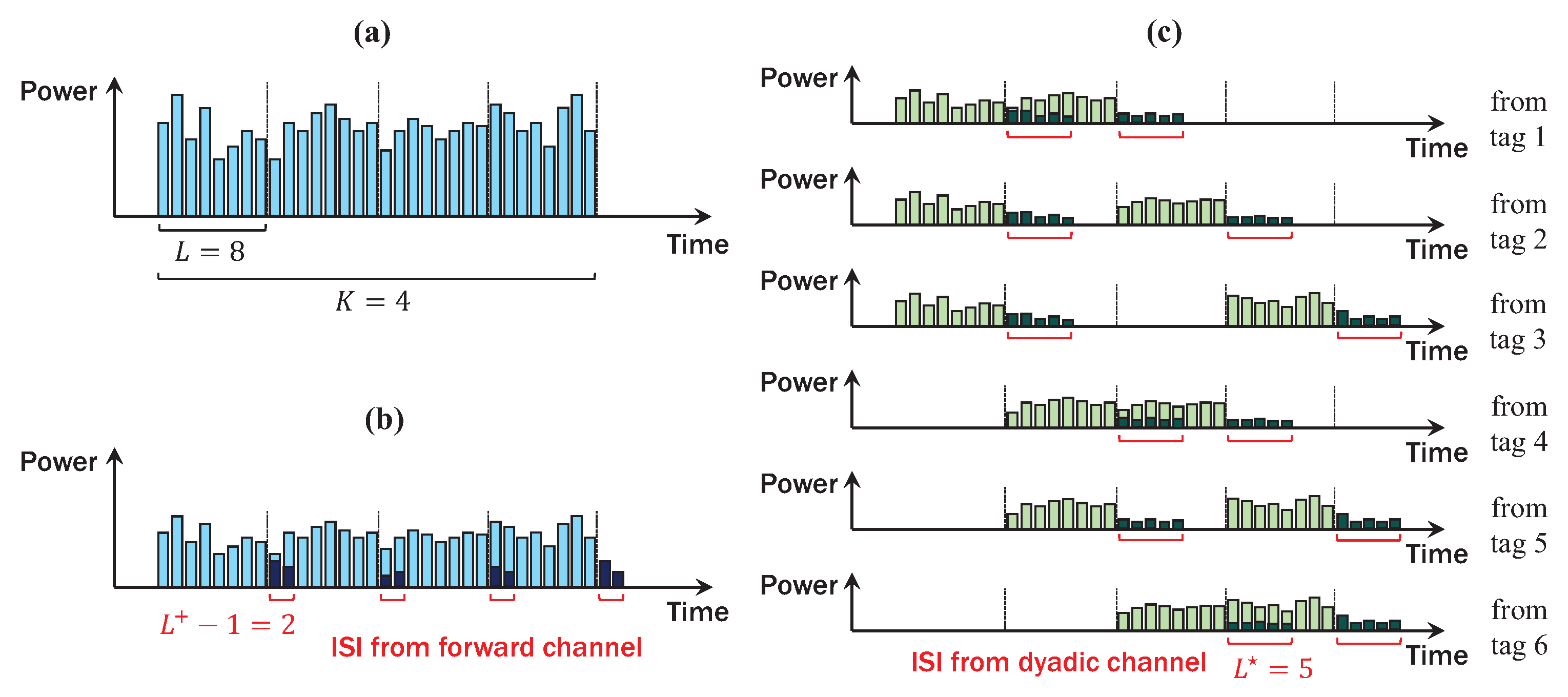
The complexity of the above problem is shown to increase exponentially with the number of tags N and polynomially with the constellation size M [32]. Fortunately, the MAP detection problem in Equation (31) can be translated into marginalize product of function (MPF) problem which can be efficiently solved by MPA [44]. In MPA, where codewords are iteratively decoded over the factor graph, we can achieve near-optimal detection performance with low complexity [32,33,39,42]. However, as described in Figure 7, DBC incurs significant ISI for detection of codeword . If we simply filter ISI using inaccurate channel estimation as in [2,23], we lose a large portion of signal power (e.g., maximum 62.5% in Figure 7c), especially for high-rate AmBC applications. Thus, to prevent the SNR loss caused by DBC, we should modify the conventional MPA [44] to exploit the weighted-sum of ISI. In addition, we adopt the log-domain MPA [43,44], which shows superior decoding performance than MPA for reliable detection of AmBC at low SNR. To achieve this goal, we define the dyadic factor graph for ambient backscatter as follows:
where the operator ⊕ denotes element-wise OR operation. In addition, by the channel reciprocity, .
Remark 3.
The dyadic factor graph with FNs and N VNs satisfies the following properties:
- There are FNs with degree and FNs with degree .
- There are K VNs with degree and VNs with degree .
If , the graph is equivalent to the spreading of the one-way factor graph with spreading factor L. As described in Figure 6, samples are collided by previous backscatter symbols causing ISI and increasing complexity of decoding. The condition ensures low-complexity decoding since the collision is only affected by neighboring backscatter symbols [23]. Especially, from Remark 3, information exchanged between FNs and VNs can be decomposed into two cases for reducing computational complexity while exploiting ISI. To perform decoding, we arrange the received signals and channels as follows:
Then, we define symbol vector composed of components as
For notational convenience, we define the ISI condition as follows:
Given the received signal , the channels , the noise variance , the tag state [15], the factor graphs and the codebooks , the initial information on FN can be formulated as
where the set denotes the VN indices connected to FN and codeword indices satisfy . If FN is affected by ISI, the initial information is modified by adding the weighted-sum of ISI represented by the codebook in Equation (38). On the other hand, the dimension of the information in Equation (38) increases exponentially as modulation order M increases [35,36]. Alternatively, we can utilize the fact that the number of symbols is much smaller than the number of codewords as described in Figure 4. For example, if , a total of eight codewords are represented in dimension with three overlapped symbols. The non-orthogonal projections of the mapping function enable low-complexity decoding even for higher values of M by compression of the information. Using codeword projection method [35,36], the information in Equation (38) can be reformulated as
Now, computational complexity at each FN is reduced for the non-ISI condition in Equation (40). Then, we assign a priori probability to initial information from VN n to FN as follows:
In the log-domain MPA, cascades of logarithm, summation and exponential operation are approximated using Jacobian logarithm and correction function for low-SNR applications. Now, we define a function as [43,44]
In the next step, FN passes the updated messages to its neighboring VNs. The intermediate variable for the log-domain MPA can be calculated as
where denotes the projected information from VN n to FN . To adapt previous works [35,36] for AmBC over L samples, we define FN indicator function as follows:
Consequently, the information is summarized in Table 1.
Then, the updated message sent to neighboring VNs from FN can be efficiently approximated as
Based on the information (46) and (47), VN n sends the updated message to FN . Assuming and denoting the indices of FNs connected to VN n as , the updated message can be represented by
where the information from FN to VN n can be expressed by
where denotes the expanded information which is also summarized in Table 1.
After iterations, VN n estimates logarithm of the probability of the code as
Finally, the log-likelihood ratio (LLR) for -th most significant bit (MSB) where for tag n can be calculated as [44]
Then, backscatter data can be detected as
Based on the iterative detector utilizing MAI and ISI, high-rate backscatter can be achievable by exploiting inherent characteristic of sparsity in ambient energy harvesting as well as DBC providing additional diversity gain.
Lemma 1.
The worst-case complexity of the iterative detector is given by
Proof.
Information from FN to VN can be decomposed into two cases. In the first case where ISI is not affected, FNs are connected to VNs, respectively, and M-ary codeword information is passed to VNs, resulting combination of information. If M-ary codeword is projected to symbols, the size of information can be reduced to using information projection [35,36]. On the other hand, FNs affected by ISI are connected to additional VNs in dyadic factor graph, resulting combination of information. Since RF tag relies on energy harvesting, the complexity of detector diminishes as density of active tags becomes sparser. ☐
As expressed in Equation (53), ISI increases complexity of the iterative detector for achieving additional diversity gain. However, the fraction of the FNs affected by the interferences is very small when for sufficiently long periods of backscatter symbols. Therefore, we can enjoy low-complexity detection even for non-orthogonal and high-order AmBC. Finally, the average sum throughput of the proposed SC-AmBC can be evaluated as
where denotes the bit rate of RF tags and the successful information decoding event and energy harvesting event are denoted by and , respectively. The probability of successful energy harvesting and information decoding can be calculated as
where ⊙ denotes exclusive-NOR operator. In conclusion, the comparison of the conventional TD-AmBC and the proposed SC-AmBC are summarized in Table 2.
5. Simulation Results
In this section, we evaluate the performance of our proposed SC-AmBC along with the conventional TD-AmBC. The simulation scenario is set as a wireless local area network (WLAN) using 2.4 GHz industrial, scientific and medical (ISM) band [57]. Applications for the AmBC would be smart home or IoT environments where massive numbers of RF devices are seamlessly integrated into existing wireless infrastructure. For AmBC, AP transmits IEEE 802.11g Wi-Fi OFDM signals [2] while tags harvest these ambient RF signals [51] and upload data streams by switching load impedances [9]. Then, RF tag in SC-AmBC modulates load impedances with non-orthogonal sparse codeword, while that in TD-AmBC modulates M impedances with TDMA [2,23]. Then, the AP in SC-AmBC receives the illuminated signals experiencing fully-correlated DBC [12,13,18,19,20,21,23] and detects data streams from these signals via the proposed D-MPA. For simplicity, we assume a system model with a single antenna at AP and no forward-error correction (FEC) codes, but extensions of our model to such scenarios are done in a straightforward manner. The AmBC is numerically evaluated by Monte Carlo simulations, since it is challenging to derive a closed-form theoretical performance in multi-dimensional constellation [39] and in the DBC [13] especially for low SNR. System parameters are summarized in Table 3.
5.1. Applicability to M-Ary Modulation
Figure 8 shows the effect of the modulation order M on the harvesting probability and the conditional BER. In a conventional TD-AmBC modulator, the harvesting probability is irrelevant to the value of M, since all the M-PSK symbols are on the circle of radius as shown in Figure 4a with in (7). Note that the reflection coefficient in the horizontal axis is related to SNR per symbol rather than SNR per bit. Consequently, as M increases, conditional BER in TD-AmBC degrades as the SNR per bit is reduced by factor [22].
On the other hand, in an SC-AmBC modulator, the harvesting probability is affected by the modulation order M and the backscatter power in (13), which can be analyzed by the value of and the threshold in (8). In 2-ary modulation, the normalized energy per symbol is given by , which is larger than those in TD-AmBC modulations. Larger value of increases the threshold value and eventually reduces the harvesting probability. Similarly, we can anticipate the performance degradation in 8-ary modulation with . However, we can observe no performance degradation, especially for 4-ary modulation. In the 4-ary SC-AmBC, the duty cycle D is doubled by using spreading sequences with factor and the backscatter power is reduced to half by using zero-constellation point represented in Figure 4b. As a result, the non-orthogonal signaling with zero symbols (i.e., idle state) in SC-AmBC can compensate the harvesting probability without energy loss.
In terms of the BER performance in Figure 8b, all of the SC-AmBC schemes outperform the TD-AmBC schemes. Extension of signal space via sparse coding can enable 1.5× overloading as well as achieve significant diversity gains. Consequently, it is noted that, for large , 4-ary SC-AmBC provides even lower BER than 2-ary TD-AmBC with the same . Although the average backscatter power is the same, SC-AmBC can utilize instantaneous channel fluctuations among different time slots, achieving modulation diversity [54]. Therefore, the proposed SC-AmBC can support small-form RF devices with M-ary modulation.
5.2. Applicability to DBC
Figure 9 shows the effect of the DBC for harvesting probability and conditional BER. The harvesting probability increases as the number of multipaths in forward channel increases. The multipath diversity reinforces the incident power at tag antenna in (5), improving efficiency of ambient energy harvesting in both the TD-AmBC and the SC-AmBC. However, multipath is harmful to BER performance in conventional TD-AmBC. To resolve ISI caused by DBC, simply filtering ISI-affected samples in detector [2,23] incurs significant loss in SNR as the number of multipath increases. Moreover, this limits the operational range of backscatter applications such as inventory control in warehouse and grocery stores [4]. Thus, we can observe the trade-off between the harvesting probability and the conditional BER in the TD-AmBC where ISI is not exploited.
On the other hand, the proposed SC-AmBC can fully exploit the ISI based on D-MPA and D-CEA. Without these algorithms, we can partially exploit the ISI for performance improvement. As shown in Figure 9b, traditional MPA for one-way channel [35,36,44] shows worse BER than those of TD-AmBC, especially in DBC. However, if we add the weighted-sum of ISI for information calculation in Equation (38) using D-MPA, the conditional BER decreases as increases, which is in sharp contrast to the conventional TD-AmBC detectors and the baseline SC-AmBC with MPA. Therefore, the proposed D-MPA with D-CEA provides multipath diversity for both the energy harvesting and the information decoding by fully exploiting ISI in DBC.
5.3. Applicability to NOMA
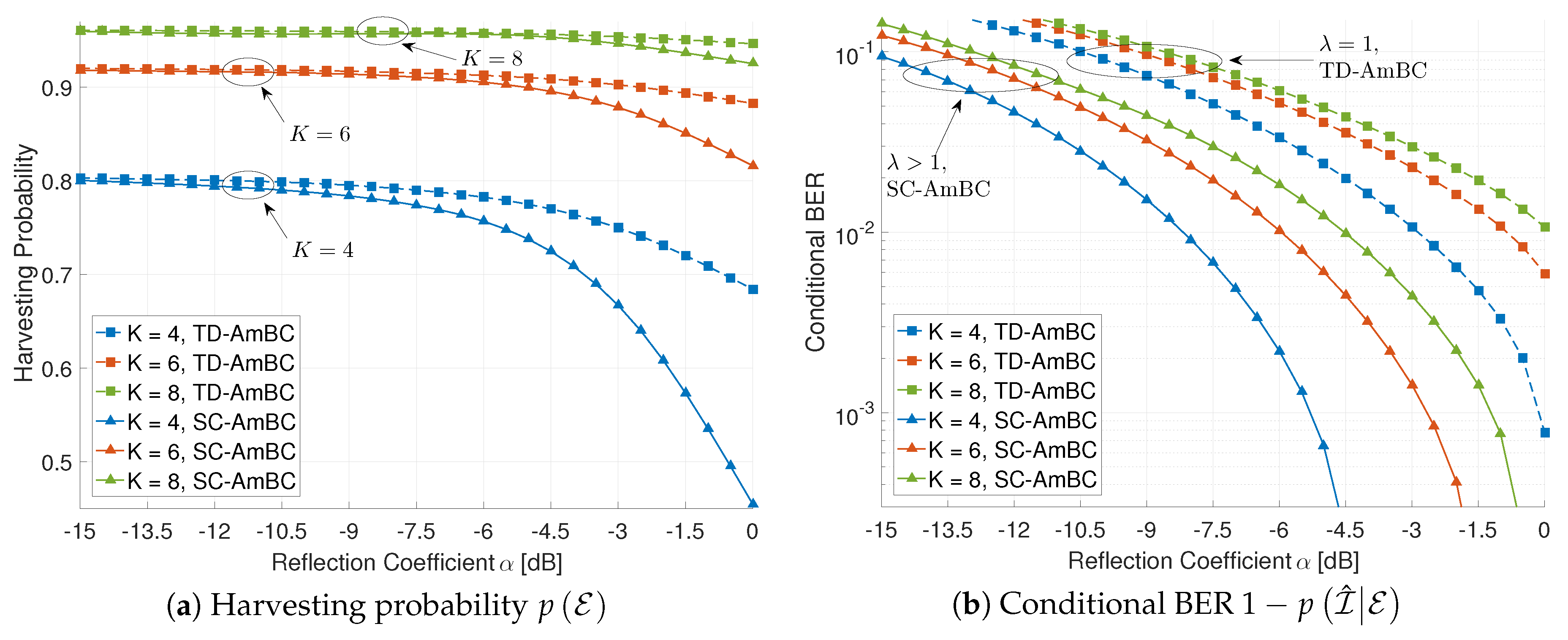
Figure 10 shows the effect of the number of time slots K on the harvesting probability and the conditional BER. Due to high computational complexity for large K, we use for this scenario. As the number of time slots K increases, the duty cycle decreases as for TD-AmBC and for SC-AmBC. Consequently, backscatter power is reduced to for TD-AmBC and for SC-AmBC, providing sufficient power to rectifier circuits in RF tags. Remarkably, increasing K reduces the performance gap between the TD-AmBC and the SC-AmBC. In this manner, increasing K improves the harvesting probability by reducing the duty cycle D in Figure 10a.
On the other hand, increasing K degrades the conditional BER as shown in Figure 10b. Since the backscatter power is reduced in both the TD-AmBC and the SC-AmBC in Equation (7), the BER performance is degraded accordingly. It is noteworthy that the TD-AmBC detectors have smaller backscatter power (i.e., ) than those of the SC-AmBC (i.e., ), exhibiting the worse BER in Figure 10b. More importantly, the sparsity caused by a small duty cycle is not utilized in those TD-AmBC detectors. Those detectors can only support OMA with a limited number of RF tags (i.e., ) and thus are not suitable for massive connectivity. The proposed SC-AmBC can efficiently utilize the sparsity for reliable AmBC detection as well as for overloading multiple RF tags (i.e., ), supporting NOMA. Although MAI may degrade the BER performance, low-complexity MPA achieves near-optimal detection performance by the virtue of the sparsity [32], As a result, the proposed SC-AmBC can enable massive and reliable connectivity over the conventional TD-AmBC.
5.4. Applicability to Energy Harvesting
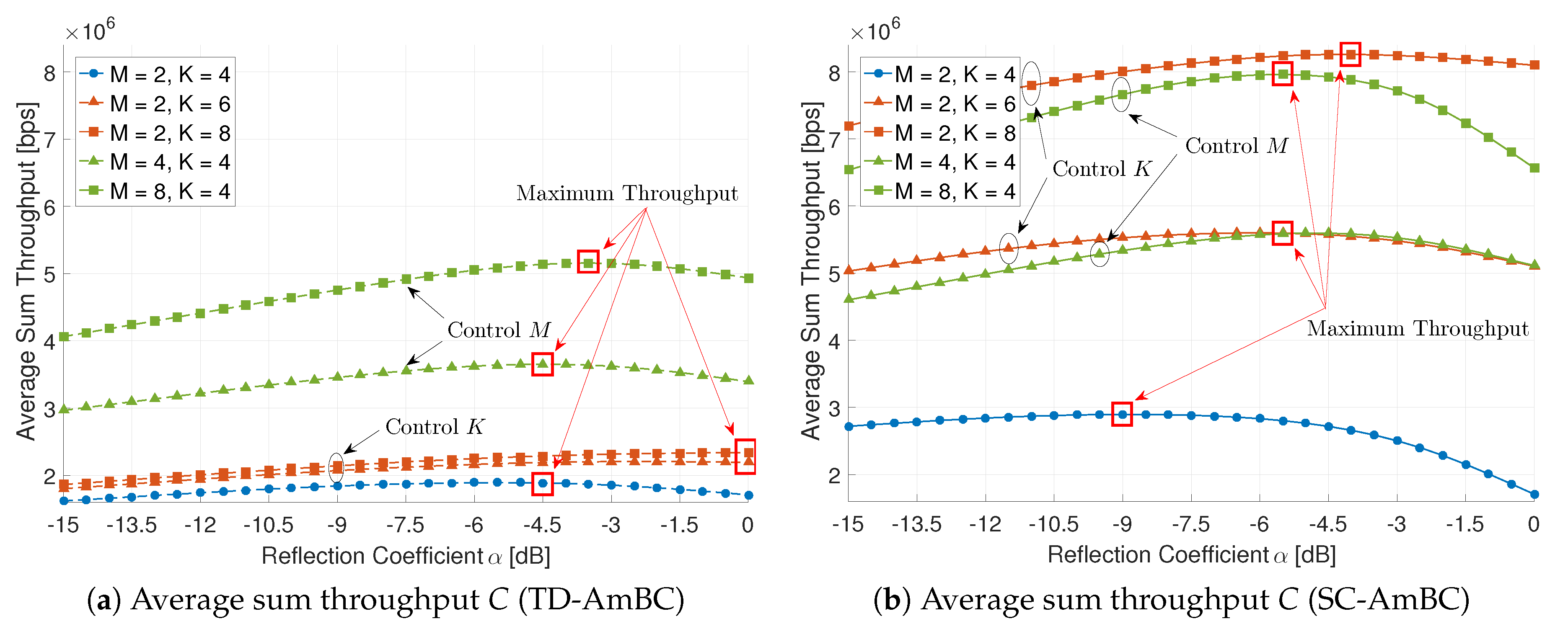
Figure 11 shows the effect of the reflection coefficient for the average sum throughput. The magnitude of reflection coefficient balances the incident power arrived at tag antenna in Equation (5) between energy harvesting and information decoding. The energy-information trade-off in AmBC determines the average sum throughput in various modulators and detectors [37]. However, in the conventional TD-AmBC, the throughput is only marginally improved as it does not exploit MAI and ISI by assuming orthogonality for the modulation and detection, as shown in Figure 11a.
The proposed SC-AmBC, on the other hand, is designed to exploit these interferences in a non-orthogonal manner. Figure 11b demonstrates the benefits of sparse coding in the throughput. Compared to Mbps throughput in TD-AmBC, the maximum throughput of SC-AmBC is Mbps, achieving an additional 60% gain. In addition, the energy-information trade-off can be flexibly adapted by controlling K, M, as well as in SC-AmBC. In conclusion, the proposed SC-AmBC is an energy-efficient solution for passive RF devices based on energy harvesting.
6. Conclusions
In this paper, we have proposed an AmBC modulator and detector based on sparse code to address low connectivity and channel fading issues inherent in AmBC. The sparse code was employed at RF tags relying on ambient energy harvesting and supports non-orthogonal concurrent backscatter communications providing massive connectivity to Wi-Fi AP. The sparse code using SC-BMA can be implemented to small-form factor RF devices and enables NOMA with M-ary modulation, achieving modulation diversity by extending the dimension of signal space. For signal detection, the iterative D-MPA and the channel estimation based on D-CEA were proposed to overcome the DBC. By exploiting MAI and ISI in modulation and detection, energy efficiency of AmBC can be enhanced, realizing massive connectivity for passive RF devices relying on energy harvesting. Therefore, SC-AmBC can be applied to batteryless IoT including biosensors, wearables and smart homes where a massive number of these RF devices are seamlessly integrated into existing wireless infrastructure.
Author Contributions
T.Y.K. has contributed to the theoretical approaches, simulation and preparing the paper; D.I.K. carried out the revisions.
Funding
This work was funded by the Korean government (MSIT) (NRF-2014R1A5A1011478).
Acknowledgments
This work was supported by the National Research Foundation of Korea (NRF) grant funded by the Korean government (MSIT) (NRF-2014R1A5A1011478).
Conflicts of Interest
The authors declare no conflict of interest.
References
- Kellogg, B.; Talla, V.; Smith, J.R.; Gollakota, S. Passive Wi-Fi: Bringing low power to Wi-Fi transmissions. In Proceedings of the 13th Usenix Symposium on Networked Systems Design and Implementation (NSDI’16), Santa Clara, CA, USA, 16–18 March 2016; pp. 151–164. [Google Scholar]
- Bharadia, D.; Joshi, K.R.; Kotaru, M.; Katti, S. BackFi: High throughput WiFi backscatter. In Proceedings of the ACM SIGCOMM’15, London, UK, 17–21 August 2015; pp. 283–296. [Google Scholar]
- Ensworth, J.F.; Reynolds, M.S. Every smart phone is a backscatter reader: Modulated backscatter compatibility with Bluetooth 4.0 low energy (BLE) devices. In Proceedings of the 2015 IEEE International Conference on RFID (IEEE RFID 2015), San Diego, CA, USA, 15–17 April 2015; pp. 78–85. [Google Scholar]
- Ma, Y.; Selby, N.; Adib, F. Drone relays for battery-free networks. In Proceedings of the ACM SIGCOMM’17, Los Angeles, CA, USA, 21–25 August 2017; pp. 335–347. [Google Scholar]
- Liu, V.; Parks, A.; Talla, V.; Gollakota, S.; Wetherall, D.; Smith, J.R. Ambient backscatter: Wireless communication out of thin air. In Proceedings of the ACM SIGCOMM’13, Hong Kong, China, 12–16 August 2013; pp. 39–50. [Google Scholar]
- Kellogg, B.; Parks, A.; Gollakota, S.; Smith, J.R.; Wetherall, D. Wi-Fi backscatter: Internet connectivity for RF-powered devices. In Proceedings of the ACM SIGCOMM’14, Chicago, IL, USA, 17–22 August 2014; pp. 607–618. [Google Scholar]
- Parks, A.N.; Liu, A.; Gollakota, S.; Smith, J.R. Turbocharging ambient backscatter communication. In Proceedings of the ACM SIGCOMM’14, Chicago, IL, USA, 17–22 August 2014; pp. 619–630. [Google Scholar]
- Thomas, S.J.; Reynolds, M.S. A 96 Mbit/sec, 15.5 pJ/bit 16-QAM modulator for UHF backscatter communication. In Proceedings of the 2012 IEEE International Conference on RFID (IEEE RFID 2012), Orlando, FL, USA, 3–5 April 2012; pp. 185–190. [Google Scholar]
- Thomas, S.J.; Wheeler, E.; Teizer, J.; Reynolds, M.S. Quadrature amplitude modulated backscatter in passive and semipassive UHF RFID systems. IEEE Trans. Microw. Theory Technol. 2012, 60, 1175–1182. [Google Scholar] [CrossRef]
- Krikidis, I. Retrodirective large antenna energy beamforming in backscatter multi-user networks. IEEE Wirel. Commun. Lett. 2018, 1–4. [Google Scholar] [CrossRef]
- Gong, S.; Huang, X.; Xu, J.; Liu, W.; Wang, P.; Niyato, D. Backscatter relay communications powered by wireless energy beamforming. IEEE Trans. Commun. 2018. [Google Scholar] [CrossRef]
- Boyer, C.; Roy, S. Space time coding for backscatter RFID. IEEE Trans. Wirel. Commun. 2013, 12, 2272–2280. [Google Scholar] [CrossRef]
- He, C.; Wang, Z.J.; Miao, C.; Leung, V.C.M. Block-level unitary query: Enabling orthogonal-link space-time code with query diversity for MIMO backscatter RFID. IEEE Trans. Wirel. Commun. 2016, 15, 1937–1949. [Google Scholar] [CrossRef]
- Talla, V.; Hessar, M.; Kellogg, B.; Najafi, A.; Smith, J.R.; Gollakota, S. LoRa backscatter: Enabling the vision of ubiquitous connectivity. Proc. ACM Interact. Mob. Wearable Ubiquitous Technol. 2017, 1, 105. [Google Scholar] [CrossRef]
- Wang, J.; Hassanieh, H.; Katabi, D.; Indyk, P. Efficient and reliable low-power backscatter networks. In Proceedings of the ACM SIGCOMM’12, Helsinki, Finland, 13–17 August 2012; pp. 61–72. [Google Scholar]
- Zhu, G.; Ko, S.-W.; Huang, K. Inference from randomized transmissions by many backscatter sensors. IEEE Trans. Wirel. Commun. 2018, 17, 3111–3127. [Google Scholar] [CrossRef]
- Liu, W.; Huang, K.; Zhou, X.; Durrani, S. Full-duplex backscatter interference networks based on time-hopping spread spectrum. IEEE Trans. Wirel. Commun. 2017, 16, 4361–4377. [Google Scholar] [CrossRef]
- Griffin, J.D.; Durgin, G.D. Link envelope correlation in the backscatter channel. IEEE Commun. Lett. 2007, 11, 735–737. [Google Scholar] [CrossRef]
- Griffin, J.D.; Durgin, G.D. Gains for RF tags using multiple antennas. IEEE Trans. Antennas Propag. 2008, 56, 563–570. [Google Scholar] [CrossRef]
- Liu, H.-C.; Lin, W.-C.; Lin, M.-Y.; Hsu, M.-H. Passive UHF RFID tag with backscatter diversity. IEEE Antennas Wirel. Propag. Lett. 2011, 10, 415–418. [Google Scholar]
- He, C.; Chen, X.; Wang, Z.J.; Su, W. On the performance of MIMO RFID backscattering channels. EURASIP J. Wirel. Commun. Netw. 2012, 11, 1–15. [Google Scholar] [CrossRef]
- Goldsmith, A. Wireless Communications; Cambridge University Press: New York, NY, USA, 2005. [Google Scholar]
- Darsena, D.; Gelli, G.; Verde, F. Modeling and performance analysis of wireless networks with ambient backscatter devices. IEEE Trans. Commun. 2017, 65, 1797–1814. [Google Scholar] [CrossRef]
- Yang, G.; Zhang, Q.; Liang, Y.-C. Cooperative ambient backscatter communications for green internet-of-things. IEEE IoT J. 2018, 5, 1116–1130. [Google Scholar] [CrossRef]
- Yang, G.; Liang, Y.-C.; Zhang, R.; Pei, Y. Modulation in the air: Backscatter communication over ambient OFDM carrier. IEEE Trans. Commun. 2018, 66, 1219–1233. [Google Scholar] [CrossRef]
- Liu, Y.; Wang, G.; Dou, Z.; Zhong, Z. Coding and detection schemes for ambient backscatter communication systems. IEEE Access 2017, 5, 4947–4953. [Google Scholar] [CrossRef]
- Lu, X.; Niyato, D.; Jiang, H.; Kim, D.I.; Xiao, Y.; Han, Z. Ambient backscatter assisted wireless powered communications. IEEE Wirel. Commun. 2018, 35, 170–177. [Google Scholar] [CrossRef]
- Dai, L.; Wang, B.; Yuan, Y.; Han, S.; Chih-Lin, I.; Wang, Z. Non-orthogonal multiple access for 5G: Solutions, challenges, opportunities, and future research trends. IEEE Commun. Mag. 2015, 53, 74–81. [Google Scholar] [CrossRef]
- Cai, Y.; Qin, Z.; Cui, F.; Li, G.Y.; McCann, J.A. Modulation and multiple access for 5G networks. IEEE Commun. Surv. Tutor. 2018, 20, 629–646. [Google Scholar] [CrossRef]
- Liu, Y.; Ding, Z.; Elkashlan, M.; Poor, H.V. Cooperative non-orthogonal multiple access with simultaneous wireless information and power transfer. IEEE J. Sel. Areas Commun. 2016, 34, 938–953. [Google Scholar] [CrossRef]
- Nissel, R.; Schwarz, S.; Rupp, M. Filter bank multicarrier modulation schemes for future mobile communications. IEEE J. Sel. Areas Commun. 2017, 35, 1768–1782. [Google Scholar] [CrossRef]
- Nikopour, H.; Baligh, H. Sparse code multiple access. In Proceedings of the 2013 IEEE 24th International Symposium on Personal Indoor and Mobile Radio Communications (PIMRC Workshops), London, UK, 8–9 September 2013; pp. 332–336. [Google Scholar]
- Taherzadeh, M.; Nikopour, H.; Bayesteh, A.; Baligh, H. SCMA codebook design. In Proceedings of the 2014 IEEE 80th Vehicular Technology Conference (VTC Fall), Vancouver, BC, Canada, 14–17 September 2014. [Google Scholar]
- Au, K.; Zhang, L.; Nikopour, H.; Yi, E.; Bayesteh, A.; Vilaipornsawai, U.; Ma, J.; Zhu, P. Uplink contention based SCMA for 5G radio access. In Proceedings of the 2014 Globecom Workshops (GC Wkshps), Austin, TX, USA, 8–12 December 2014; pp. 900–905. [Google Scholar]
- Wu, Y.; Zhang, S.; Chen, Y. Iterative multiuser receiver in sparse code multiple access systems. In Proceedings of the 2015 IEEE International Conference on Communications (ICC), London, UK, 8–12 June 2015; pp. 2918–2923. [Google Scholar]
- Bayesteh, A.; Nikopour, H.; Taherzadeh, M.; Baligh, H.; Ma, J. Low complexity techniques for SCMA detection. In Proceedings of the 2015 Globecom Workshops (GC Wkshps), San Diego, CA, USA, 6–10 December 2015. [Google Scholar]
- Han, K.; Huang, K. Wirelessly powered backscatter communication networks: Modeling, coverage and capacity. IEEE Trans. Wirel. Commun. 2017, 16, 2548–2561. [Google Scholar] [CrossRef]
- Boyer, C.; Roy, S. Coded QAM backscatter modulation for RFID. IEEE Trans. Commun. 2012, 60, 1925–1934. [Google Scholar] [CrossRef]
- Zhou, Y.; Yu, Q.; Meng, W.; Li, C. SCMA codebook design based on constellation rotation. In Proceedings of the 2017 IEEE International Conference on Communications (ICC), Paris, France, 21–25 May 2017. [Google Scholar]
- Talla, V.; Smith, J.R. Hybrid analog-digital backscatter: A new approach for battery-free sensing. In Proceedings of the 2013 IEEE International Conference on RFID (IEEE RFID 2013), Penang, Malaysia, 30 April–2 May 2013; pp. 74–81. [Google Scholar]
- Bharadia, D.; McMilin, E.; Katti, S. Full duplex radios. In Proceedings of the ACM SIGCOMM’13, Hong Kong, China, 12–16 August 2013; pp. 375–386. [Google Scholar]
- Peng, J.; Chen, W.; Bai, B.; Guo, X.; Sun, C. Joint optimization of constellation with mapping matrix for SCMA codebook design. IEEE Signal Process. Lett. 2017, 24, 264–268. [Google Scholar] [CrossRef]
- Robertson, P.; Villebrun, E.; Hoeher, P. A comparison of optimal and sub-optimal MAP decoding algorithms operating in the log domain. In Proceedings of the 1995 IEEE International Conference on Communications (ICC), Seattle, WA, USA, 18–22 June 1995; pp. 1009–1013. [Google Scholar]
- Hoshyar, R.; Wathan, F.P.; Tafazolli, R. Novel low-density signature for synchronous CDMA systems over AWGN channel. IEEE Trans. Signal Process. 2008, 56, 1616–1626. [Google Scholar] [CrossRef] [Green Version]
- Sabharwal, A.; Schniter, P.; Guo, D.; Bliss, D.W.; Rangarajan, S.; Wichman, R. In-band full-duplex wireless: Challenges and opportunities. IEEE J. Sel. Areas Commun. 2014, 32, 1637–1652. [Google Scholar] [CrossRef]
- Zhang, Z.; Chai, X.; Long, K.; Vasilakos, A.V.; Hanzo, L. Full duplex techniques for 5G networks: Self-interference cancellation, protocol design, and relay selection. IEEE Commun. Mag. 2015, 53, 128–137. [Google Scholar] [CrossRef]
- Donoho, D.L. Compressed sensing. IEEE Trans. Inf. Theory 2006, 52, 1289–1306. [Google Scholar] [CrossRef]
- Wang, G.; Gao, F.; Fan, R.; Tellambura, C. Ambient backscatter communication systems: Detection and performance analysis. IEEE Trans. Commun. 2016, 64, 4836–4846. [Google Scholar] [CrossRef]
- Qian, J.; Gao, F.; Wang, G.; Jin, S.; Zhu, H. Noncoherent detections for ambient backscatter system. IEEE Trans. Wirel. Commun. 2017, 16, 1412–1422. [Google Scholar] [CrossRef]
- Wang, Z.; Giannakis, G.B. Wireless multicarrier communications—Where Fourier meets Shannon. IEEE Signal Process. Mag. 2000, 17, 29–48. [Google Scholar] [CrossRef]
- Kim, Y.-H.; Ahn, H.-S.; Yoon, C.; Lim, Y.; Lim, S.-O. An ambient RF energy harvesting and backscatter modulating tag system enabling zero-power wireless data communication. In Proceedings of the Seventh International Conference on the Internet of Things (IoT ’17), Linz, Austria, 22–25 October 2017. [Google Scholar]
- Besnoff, J.; Abbasi, M.; Ricketts, D.S. High data-rate communication in near-field RFID and wireless power using higher order modulation. IEEE Trans. Microw. Theory Technol. 2016, 64, 401–413. [Google Scholar] [CrossRef]
- Jordao, M.; Correia, R.; Carvalho, N.B. High order modulation backscatter systems characterization. In Proceedings of the 2018 IEEE Topical Conference on Wireless Sensors and Sensor Networks (WiSNet), Anaheim, CA, USA, 14–17 January 2018; pp. 44–46. [Google Scholar]
- Boutros, J.; Viterbo, E. Signal space diversity: A power- and bandwidth-efficient diversity technique for the Rayleigh fading channel. IEEE Trans. Inf. Theory 1998, 44, 1453–1467. [Google Scholar] [CrossRef]
- Choi, J.W.; Shim, B.; Ding, Y.; Rao, B.; Kim, D.I. Compressed sensing for wireless communiciations: Useful tips and tricks. IEEE Surv. Tutor. 2017, 19, 1527–1550. [Google Scholar] [CrossRef]
- Yang, G.; Ho, C.K.; Zhang, R.; Guan, Y.L. Throughput optimization for massive MIMO systems powered by wireless energy transfer. IEEE J. Sel. Areas Commun. 2015, 33, 1640–1650. [Google Scholar] [CrossRef]
- ISO/IEC Standard for Information Technology—Telecommunications and Information Exchange between Systems—Local and Metropolitan Area Networks—Specific Requirements Part 11: Wireless LAN Medium Access Control (MAC) and Physical Layer (PHY) Specifications; ISO/IEC 8802-11 IEEE Std 802.11 Second edition 2005-08-01 ISO/IEC 8802 11:2005(E) IEEE Std 802.11i-2003 Edition; IEEE: Piscataway, NJ, USA, 2005; pp. 1–721.
Figure 1.
Proposed AmBC network with single AP and multiple RF tags employing ambient RF energy harvesting and backscatter communications using sparse code.
Figure 1.
Proposed AmBC network with single AP and multiple RF tags employing ambient RF energy harvesting and backscatter communications using sparse code.
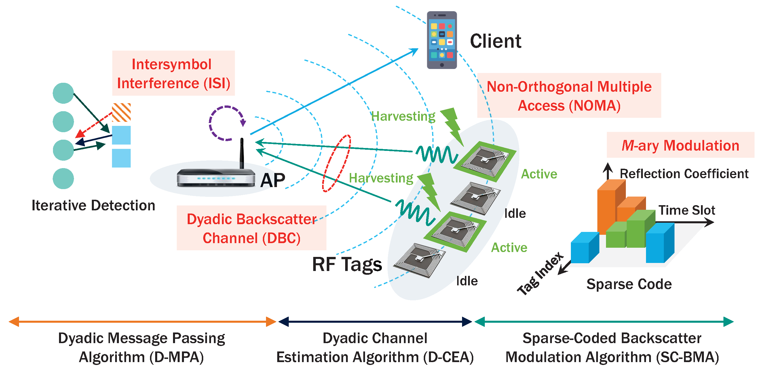
Figure 2.
Link layer protocol for AmBC with sparse code.

Figure 3.
Example of duty-cycling operation per codeword of length .

Figure 4.
Example of mapping function for AmBC. (a) PSK-based backscatter modulator; (b) sparse-coded backscatter modulator.
Figure 4.
Example of mapping function for AmBC. (a) PSK-based backscatter modulator; (b) sparse-coded backscatter modulator.

Figure 5.
Example of multidimensional mapping function. (a) ; (b) ; (c) .

Figure 6.
Example of dyadic factor graph composed of forward factor graph and backward factor graph (, , , , ).
Figure 6.
Example of dyadic factor graph composed of forward factor graph and backward factor graph (, , , , ).

Figure 7.
Example of AmBC signals in DBC (, , ). (a) transmitted signal from AP; (b) received signal at tag with ISI from forward channel; (c) superposition signal at AP with ISI from a dyadic channel.
Figure 7.
Example of AmBC signals in DBC (, , ). (a) transmitted signal from AP; (b) received signal at tag with ISI from forward channel; (c) superposition signal at AP with ISI from a dyadic channel.

Figure 8.
Effect of the modulation order M (, , for SC-AmBC).
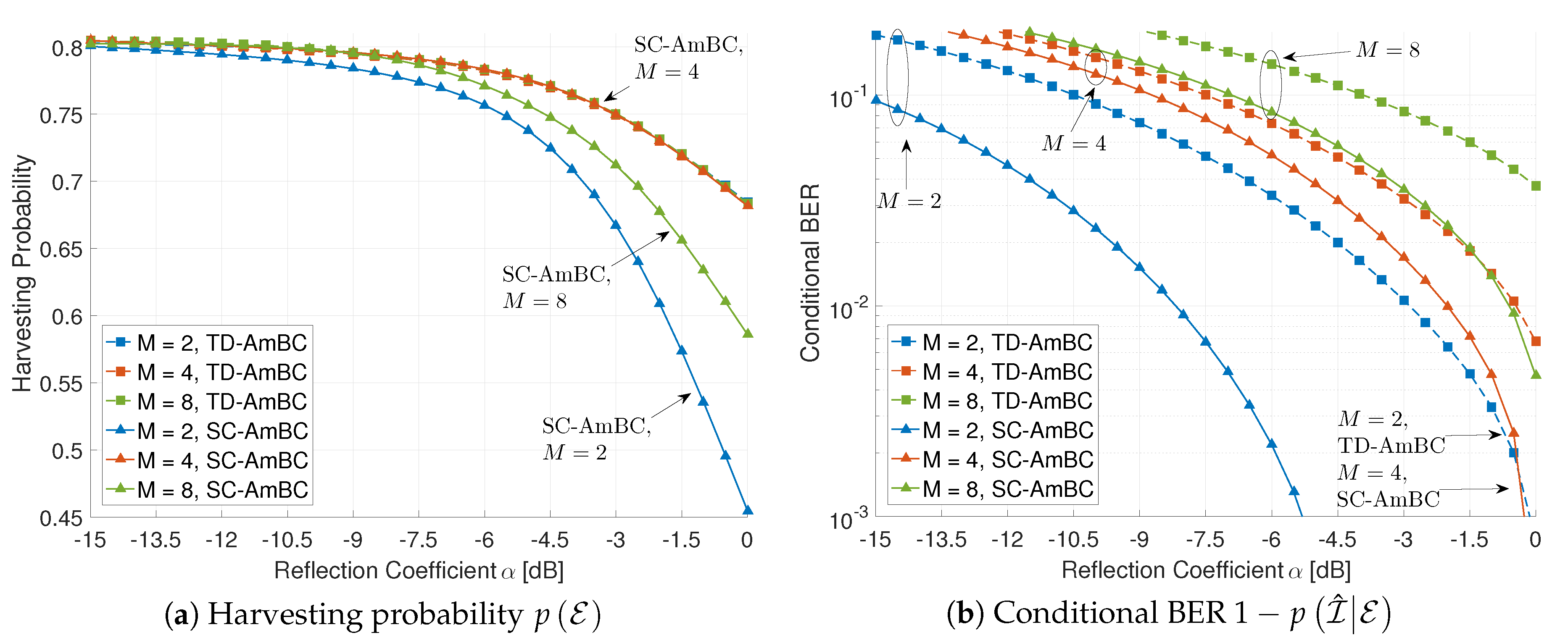
Figure 9.
Effect of the number of multipath (, , for SC-AmBC).
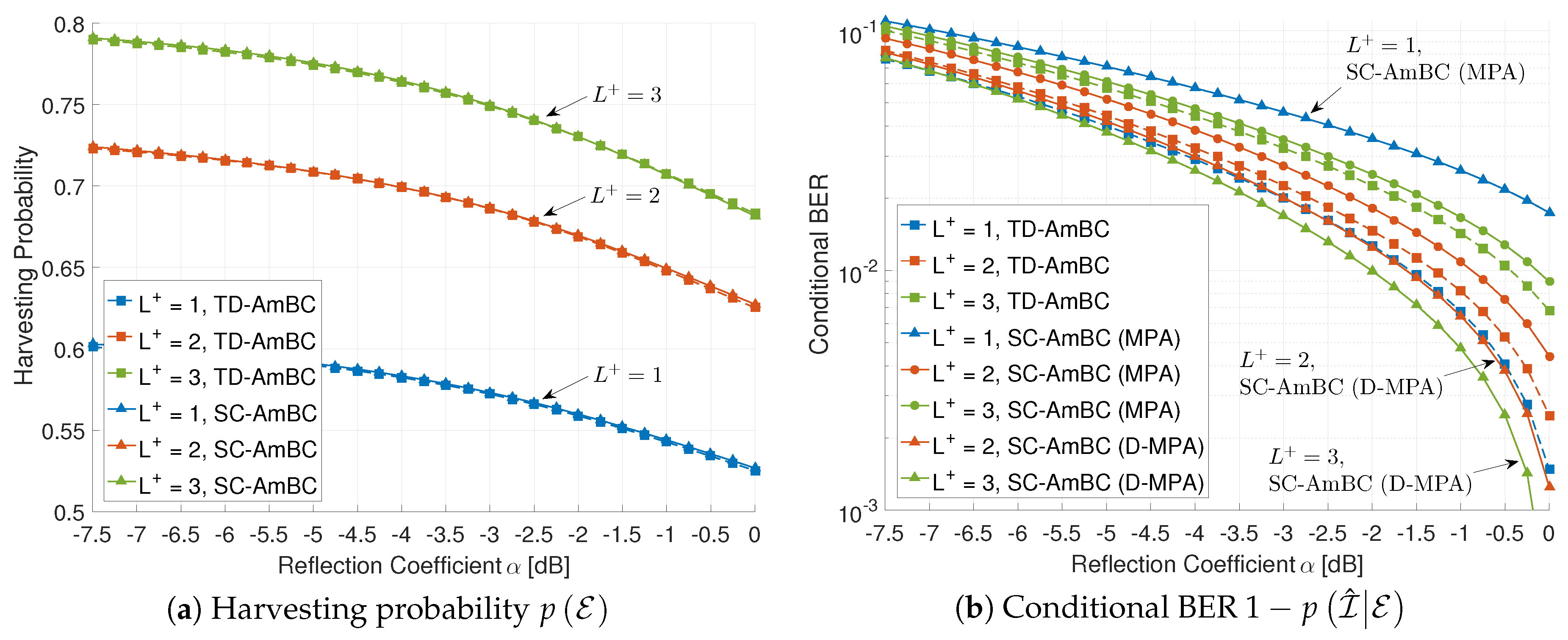
Figure 10.
Effect of the number of time slots K (, ).

Figure 11.
Effect of the reflection coefficient ().

Table 1.
Table of information projections and expansions (VN: variable node, FN: factor node).
| M | Projected Information from VN n to FN | |
|---|---|---|
| 4 | 1 | |
| 2 | ||
| 8 | 1 | |
| 2 | ||
| Expanded Information from FN to VN | ||
| 4 | 1 | |
| 2 | ||
| 8 | 1 | |
| 2 | ||
Table 2.
Comparison of the conventional TD-AmBC and the proposed SC-AmBC.
| TD-AmBC [2,23] | SC-AmBC | ||
|---|---|---|---|
| Modulation | Load impedances | M | 2 |
| Constellation dimension | 2 | ||
| Constellation symbols | M | ||
| Detection | ISI exploitation | no | yes |
| MAI exploitation | no | yes | |
| Complexity | low | medium | |
| BER | high | low | |
| Networking | Max. sum throughput | ||
| Max. connectivity | K | ||
| Duty cycle | |||
| Latency | high | low | |
| Multiple access | orthogonal | non-orthogonal |
© 2018 by the authors. Licensee MDPI, Basel, Switzerland. This article is an open access article distributed under the terms and conditions of the Creative Commons Attribution (CC BY) license (http://creativecommons.org/licenses/by/4.0/).
Share and Cite
MDPI and ACS Style
Kim, T.Y.; Kim, D.I. Novel Sparse-Coded Ambient Backscatter Communication for Massive IoT Connectivity. Energies 2018, 11, 1780. https://doi.org/10.3390/en11071780
AMA Style
Kim TY, Kim DI. Novel Sparse-Coded Ambient Backscatter Communication for Massive IoT Connectivity. Energies. 2018; 11(7):1780. https://doi.org/10.3390/en11071780
Chicago/Turabian StyleKim, Tae Yeong, and Dong In Kim. 2018. "Novel Sparse-Coded Ambient Backscatter Communication for Massive IoT Connectivity" Energies 11, no. 7: 1780. https://doi.org/10.3390/en11071780
Note that from the first issue of 2016, this journal uses article numbers instead of page numbers. See further details here.