Article

Improvement in Harmonic Compensation of a Smart Charger with a Constant DC-Capacitor Voltage-Control-Based Strategy for Electric Vehicles in Single-Phase Three-Wire Distribution Feeders

1
Department of Electrical and Electronic Engineering, Yamaguchi University, 2-16-1 Tokiwadai, Ube, Yamaguchi 755-8611, Japan
2
Department of Electrical Engineering, National Institute of Technology, Ube College, 2-14-1 Tokiwadai, Ube, Yamaguchi 755-8555, Japan
*
Author to whom correspondence should be addressed.
These authors contributed equally to this work.
Energies 2018, 11(6), 1604; https://doi.org/10.3390/en11061604
Submission received: 19 April 2018 / Revised: 10 June 2018 / Accepted: 14 June 2018 / Published: 19 June 2018
(This article belongs to the Special Issue Power Electronics for Energy Storage)

Abstract

:
This paper presents an improvement in harmonic compensation performance of a previously proposed smart charger (SC) with a constant dc-capacitor voltage-control (CDCVC) strategy for electric vehicles (EVs) in single-phase three-wire distribution feeders (SPTWDFs). A controller for 3rd harmonic currents in d-q coordinates is added to the previously proposed SC. This addition improves harmonic compensation performance of the source currents. We briefly introduce harmonic current compensation using the previously proposed CDCVC-based algorithm for the SC. Then, the basic principles of the proposed controller for the 3rd harmonic currents in d-q coordinates are discussed in detail. It is shown that synchronization of the current controllers for both the fundamental and 3rd harmonic components is required. The switching frequency of a three-leg pulse-width modulated rectifier with a bidirectional dc–dc converter, which performs the SC, is determined considering the synchronization of the current controllers. Simulation and experimental results demonstrate that balanced and sinusoidal source currents with a unity power factor are achieved during both battery charging and discharging operations in EVs, improving the harmonic compensation performance of the previously proposed SC. Experimental results also demonstrate that the total harmonic distortion values of source currents are improved by 8.4% and 3.6% with the proposed controller for 3rd harmonic currents, when the SC is discharging, for example.

1. Introduction

Single-phase three-wire distribution feeders (SPTWDFs) with pole-mounted distribution transformers (PMDTs) are widely used for home appliances in Japan. However, load conditions in the two feeders are always unbalanced, because the home appliances used by domestic consumers are often changed. Load conditions cause unbalanced source voltages and affect power quality on the secondary side of the PMDT. Domestic consumers who affect the power quality should pay extra charges to the power companies, as these cause economic losses in the distribution feeders. Conversely, domestic consumers with high-quality home appliances that improve the power quality on the secondary side of PMDTs may be entitled to buy power at a reduced rate. It is natural that domestic consumers should be responsible for improving the power quality in the distribution feeders. The present authors, therefore, proposed a smart charger (SC) for electric vehicles (EVs) with a power-quality compensator, which can improve the power quality for domestic consumers [1]. The proposed SC is comprised of a three-leg pulse-width modulated (PWM) rectifier and a bidirectional dc–dc converter. The rectifier can compensate fundamental reactive and fundamental unbalanced active currents in SPTWDFs. For the control strategy, a constant dc-capacitor voltage-control (CDCVC) strategy was used. The CDCVC-based control strategy achieves balanced source currents with a unity power factor (PF). Many diode rectifiers are included in modern home appliances and connected to SPTWDFs. These diode rectifiers generate harmonic currents. The authors also dealt with harmonic current compensation with a CDCVC-based strategy in SPTWDFs with diode rectifiers [2]. Simulation and experimental results demonstrated that balanced and sinusoidal source currents with a unity PF are obtained during both battery charging and discharging operations in EVs. The 3rd harmonic currents remained in the source currents and affect the total harmonic distortion (THD) values of the source currents. The 3rd harmonic currents are dominant in single-phase circuits while the 5th and 7th harmonic currents are dominant in three-phase circuits. Therefore, suppressing these 3rd harmonic currents of the sources is necessary to improve the THD values in SPTWDFs.
In this paper, an improvement in harmonic compensation performance of the proposed SC with a CDCVC strategy is presented. A current controller for the 3rd harmonic currents with proportional-integral (PI) controllers in d-q coordinates is added to the previously proposed SC. Addition of the current controller for the 3rd harmonic currents improves the harmonic compensation performance of the CDCVC strategy. First, we briefly introduce harmonic current compensation with the previously proposed CDCVC-based algorithm for SC. Then, the basic principles of the proposed current controller for the 3rd harmonic current in d-q coordinates are discussed in detail. It is shown that a synchronization of the current controllers in d-q coordinates for both the fundamental and 3rd harmonic components is required. The switching frequency of the three-leg PWM rectifier with a bidirectional dc-dc converter, which performs SC, is determined considering the synchronization of the current controllers. Simulation and experimental results demonstrate that balanced and sinusoidal source currents with a unity PF are obtained during both battery charging and discharging operations in EVs, thereby improving the harmonic compensation performance of the SC.

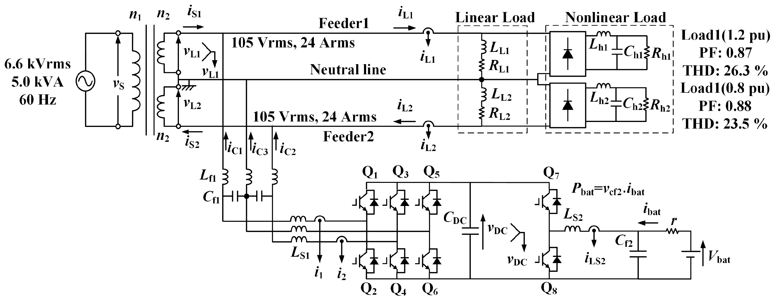
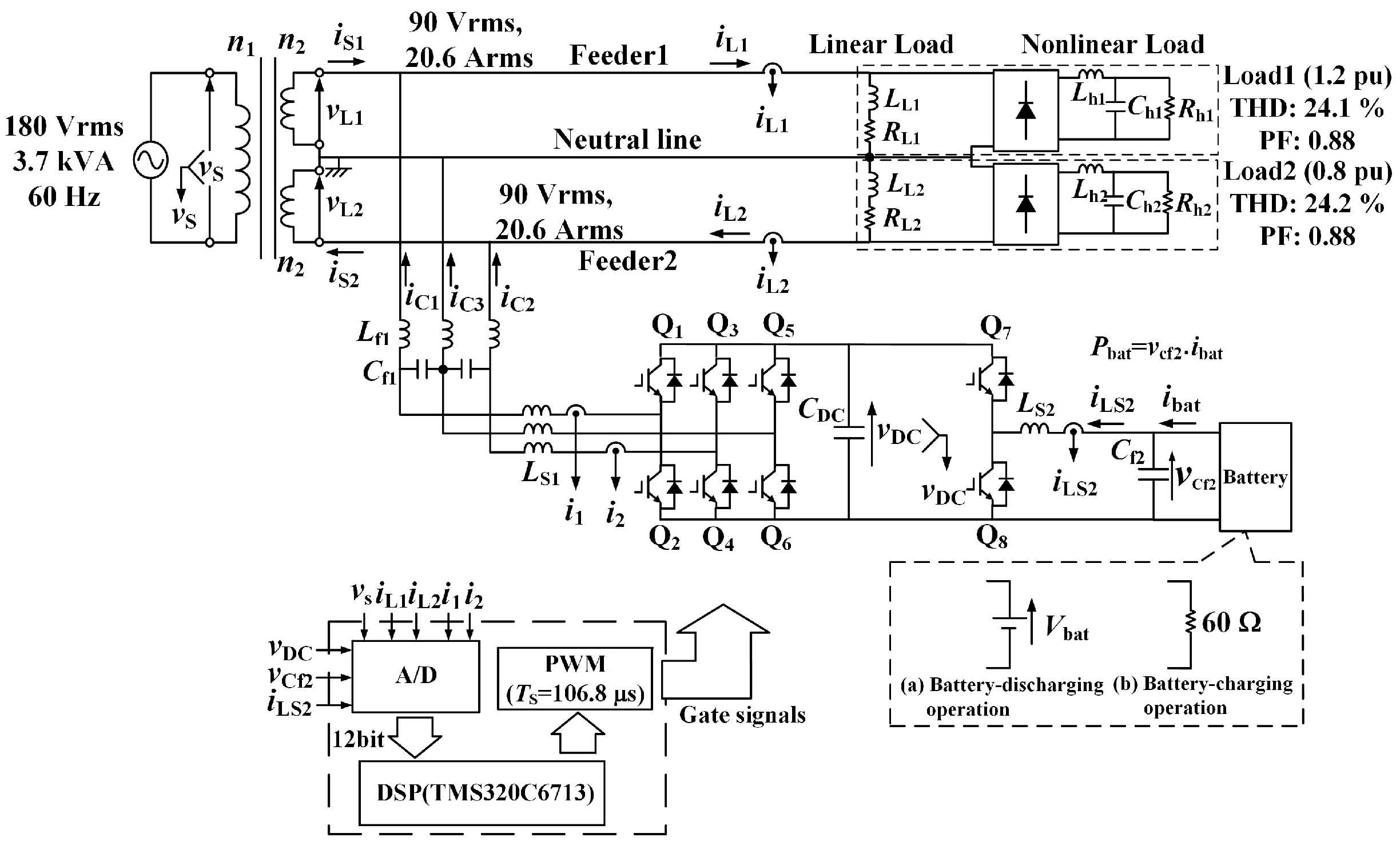
2. Smart Charger for EVs

Figure 1 shows the system configuration of the previously proposed SC [1] and Figure 2 shows the control circuit diagram of the CDCVC-based strategy for Figure 1. The instantaneous active–reactive power theory in three-phase circuits, the so-called pq theory, was proposed by H. Akagi et al. [3] and is widely used for active power-line conditioners in three-phase circuits. Additionally, this theory was applied to three-phase four-wire systems by F. Z. Peng et al. [4]. Other methods in three-phase systems were proposed [5,6,7]. A single-phase pq theory was proposed [8]. If the single-phase pq theory is used for the SC in Figure 2, we obtain the control circuit diagram of Figure 3. The part enclosed by the dotted line shows the instantaneous active power calculation block. Note that the CDCVC block is also included in Figure 3. However, in Figure 2 only the CDCVC is included; no operation blocks for the reactive, unbalanced active, and harmonic components are included. Therefore, the proposed CDCVC-based strategy for SCs is simple. This simplified strategy attains balanced-sinusoidal source currents with a unity power factor (PF).

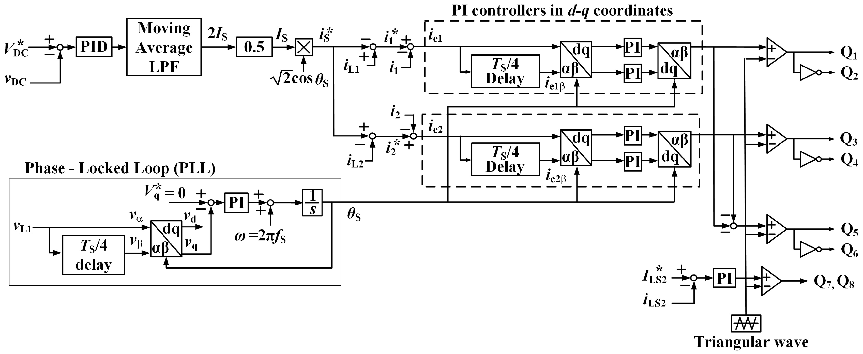
2.1. Constant DC-Capacitor Voltage-Control Strategy for Harmonic Compensation

The previously proposed CDCVC-based strategy, of Figure 2 for the system in Figure 1, is briefly introduced. If the primary-side voltage v S and the secondary-side voltages v L 1 and v L 2 are purely sinusoidal, v S , v L 1 , and v L 2 are expressed as:
v S = 2 V S cos ω S t , v L = v L 1 = v L 2 = 2 V L cos ω S t .
With the nonlinear loads, the load currents i L 1 and i L 2 in feeders 1 and 2 are given by:
i L 1 = 2 I L 1 F cos ω S t ϕ L 1 F + 2 n = 2 I L 1 n cos n ω S t ϕ L 1 n , i L 2 = 2 I L 2 F cos ω S t ϕ L 2 F + 2 n = 2 I L 2 n cos n ω S t ϕ L 2 n .
Assume that the source-side currents i S 1 and i S 2 are balanced and sinusoidal with a unity PF by the SC using the CDCVC-based strategy, while the load currents i L 1 and i L 2 are unbalanced and distorted. The aimed source-currents i S * , i S 1 * , and i S 2 * are expressed as:
i S * = i S 1 * = i S 2 * = 2 I S cos ω S t ,
where I S is the root-mean square (RMS) value of i S * . In Figure 1, the reference values of the output currents i 1 * , i 2 * , and i 3 * of the three-leg PWM rectifier are given by:
i 1 * = i L 1 i S 1 * , i 2 * = i L 2 + i S 2 * , i 3 * = ( i 1 * + i 2 * ) .
When the output currents i C 1 , i C 2 , and i C 3 of the three-leg PWM rectifier are perfectly controlled to i 1 * , i 2 * , and i 3 * , the output currents i C 1 , i C 2 , and i C 3 are expressed as:
i C 1 = i 1 * , i C 2 = i 2 * , i C 3 = i 3 * .
The instantaneous power flow p SC into the SC, which contains the three-leg PWM rectifier, is given by:
p SC = v L 1 · i C 1 + v L 2 · i C 2 = V L { I L 1 F cos ϕ L 1 F I L 2 F cos ϕ L 2 F + 2 I S + I L 1 F cos ϕ L 1 F I L 2 F cos ϕ L 2 F cos 2 ω S t + I L 1 F sin ϕ L 1 F I L 2 F sin ϕ L 2 F sin 2 ω S t n = 2 I L 1 n cos ϕ L 1 n + I L 2 n cos ϕ L 2 n cos n ω S t cos ω S t n = 2 I L 1 n sin ϕ L 1 n + I L 2 n sin ϕ L 2 n sin n ω S t cos ω S } .
If the dc-capacitor voltage, v DC , is kept constant by the CDCVC strategy, the average value p ¯ SC should be P bat because the power charged or discharged to/from the battery is exchanged to the utility grid with the dc capacitor C DC . Therefore, p ¯ SC is given by:
p ¯ SC = V L I L 1 F cos ϕ L 1 F I L 2 F cos ϕ L 2 F + 2 I S = P bat .
Given p ¯ SC = P bat , the RMS value I S —of i S * , i S 1 * , and i S 2 * in Equation (3)—is expressed as:
I S = I L 1 F cos ϕ L 1 F + I L 2 F cos ϕ L 2 F 2 + P bat 2 V L .
In Figure 2, the targeted source currents i S * , i S 1 * , and i S 2 * are generated by 2 I S , which is the output value of the proportional–integral–derivative (PID) controller, with 2 cos ω s . Equation (8) gives us an important implication that the average value p ¯ SC is P bat when the output value of the PID controller in the CDCVC equals 2 I S . Using the CDCVC-based strategy of Figure 2 achieves balanced and sinusoidal source currents i S 1 and i S 2 with a unity PF, as expressed by Equation (3), when charging or discharging the power P bat from/to the utility grid, even though the load currents i L 1 and i L 2 are unbalanced and distorted.
The dc-capacitor voltage v DC is detected. The difference Δ v DC between the reference value V DC * and v DC is amplified by the PID controller, and then the RMS value I S (of i S * , i S 1 * , and i S 2 * ) is calculated. A moving-average low-pass filter (MALPF) is used to remove the 2 ω s component in the output signal of the PID controller, where ω s is the angular frequency of the source voltage v S . The reference active current i S * , which is given by Equation (3), is calculated by multiplying I S with 2 cos θ s . Here, to generate the electric angle θ s = ω s t of v S , a phase-locked loop (PLL) with a single phase is used [9,10]. The primary-side voltage v S is detected. This v S corresponds to the α -phase component v α . The detected voltage is delayed by T S / 4 , where T S is a cycle of v S , and this delayed voltage corresponds to the β -phase component v β . These v α and v β are transformed to v d and v q in d-q coordinates with θ s , respectively [11]. Controlling v q to zero by a PI controller in d-q coordinates, an electric angle θ s = ω s t , which is synchronized with v S , can be generated. Finally, by subtracting the calculated i S * from the detected i L 1 and i L 2 , the reference values i 1 * , i 2 * , and i 3 * for the three-leg PWM rectifier are calculated as:
i 1 * = i L 1 i S * , i 2 * = i L 2 + i S * , i 3 * = i 1 * + i 2 * .
Steady-state error persists when a triangle intersection method current controller with a PI controller in a single-phase PWM rectifier is used. To suppress this steady-state error, a current feedback control method in d-q coordinates for single-phase circuits was proposed [11]. In feeder 1 in Figure 1, for example, the difference i e 1 between the reference value i 1 * and the detected i 1 is calculated. This calculated difference i e 1 corresponds to the α -phase component in α - β coordinates. The calculated difference i e 1 is then delayed by T S / 4 , where this delayed component correspond to the β -phase component. These are transformed into d-q coordinates with θ s , which is generated by the single-phase PLL. The current controllers in d-q coordinates for the fundamental components are achieved. These current controllers in d-q coordinates can suppress steady-state error because only the fundamental components in α - β coordinates will become dc components in d-q coordinates.
Figure 4 shows simulation results for the previously proposed SC with the CDCVC-based strategy of Figure 2. v L 1 and v L 2 are the secondary-side voltage waveforms, and i S 1 and i S 2 are the secondary-side current waveforms. i L 1 and i L 2 are the load-side current waveforms at the domestic consumer’s end; i C 1 , i C 2 , and i C 3 are the output currents waveforms of the SC; v DC is the dc-capacitor voltage waveform; and i LS 2 is the inductor current waveform. Although the load currents i L 1 and i L 2 are unbalanced and distorted, the source currents i S 1 and i S 2 are balanced with unity PF. However, the source currents i S 1 and i S 2 were slightly distorted. The THD values of i S 1 and i S 2 were 10.8% and 7.7%, respectively. Figure 5 shows the spectra of the source currents i S 1 and i S 2 from the simulation. It is well known that the 3rd harmonic currents are dominant in single-phase circuits. In Figure 5, a large contribution from 3rd harmonic currents is found in the source currents i S 1 and i S 2 . These 3rd harmonic components affect the THD values of i S 1 and i S 2 . Therefore, this paper introduces an improvement of harmonic compensation performance on the source side in Figure 1.

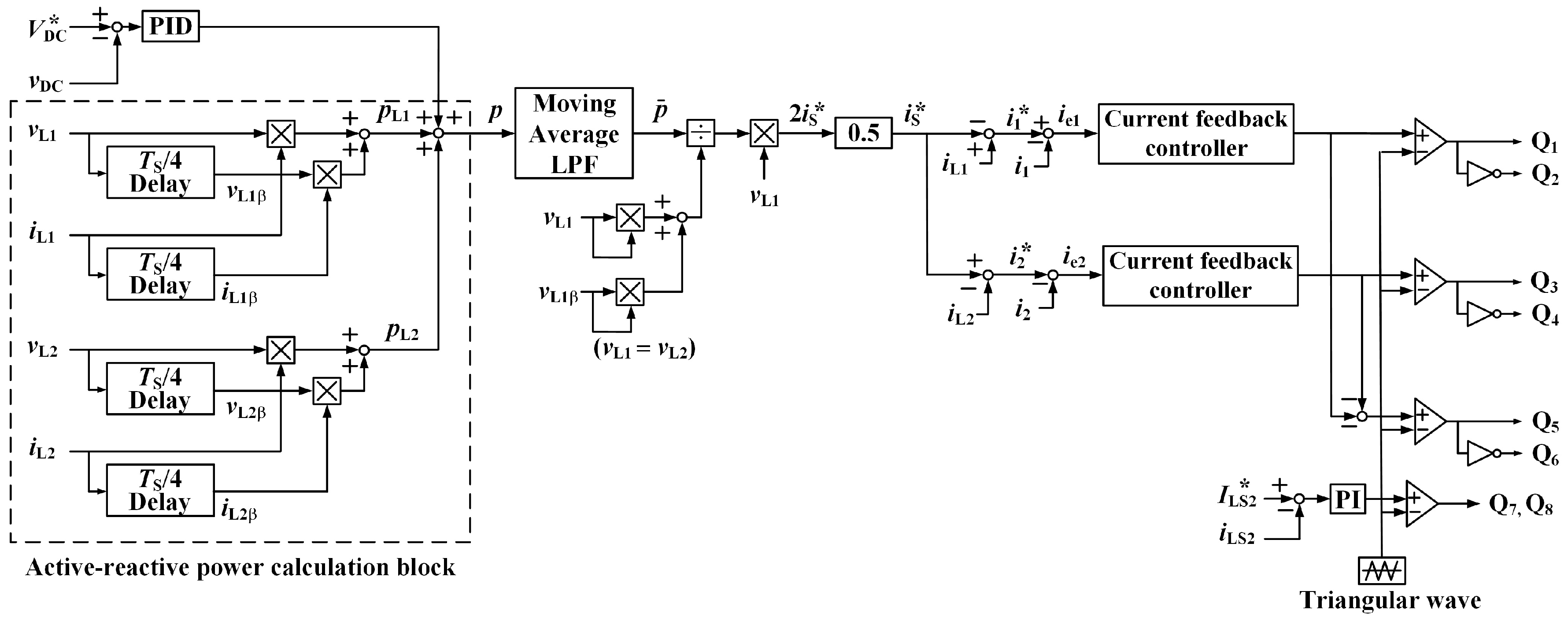
2.2. Improvement in Harmonic Compensation for a Smart Charger

The authors propose a current controller in d-q coordinates for the 3rd harmonic currents to improve harmonic compensation on the source side for the system in Figure 1. Figure 6 shows the proposed control circuit diagram for the SC of Figure 1. The part enclosed by the dotted line shows the proposed PI controllers in d-q coordinates for the 3rd harmonic components. For example, feeder 1 in Figure 6 detects the output current i 1 , and then the difference i e 1 between the reference value i 1 * and the detected output current i 1 is calculated. This i e 1 corresponds to the α -phase component. For the sake of simplicity, only the fundamental, 3rd, and 5th components are included in i e 1 :
i e 1 = 2 I F cos ω S t ϕ F + 2 I 3 cos 3 ω S t ϕ 3 + 2 I 5 cos 5 ω S t ϕ 5 .
Then, i e 1 is delayed by T S /12, where T S /12 equals π /2 for the 3rd harmonic components in the electric angle. Delaying i e 1 by T S /12 is an original concept to construct the current controllers in d-q coordinates for the 3rd harmonic currents. The delayed component i e 31 β is given by:
i e 31 β = 2 I F cos ω S t ϕ F π 6 + 2 I 3 cos 3 ω S t ϕ 3 π 2 + 2 I 5 cos 5 ω S t ϕ 5 5 π 6 = 2 I F cos ω S t ϕ F π 6 + 2 I 3 sin 3 ω S t ϕ 3 + 2 I 5 cos 5 ω S t ϕ 5 5 π 6 .
With the angular frequency 3 ω S for the 3rd harmonic component, i d 31 and i q 31 in d-q coordinates are generally expressed as:
i d 31 i q 31 = cos 3 ω S sin 3 ω S sin 3 ω S cos 3 ω S i e 1 i 31 β .
Substituting i e 1 in Equation (10) and i e 31 β in Equation (11) into Equation (12) gives:
i d 31 = 2 2 I F { cos 4 ω S t ϕ F + cos 2 ω S t + ϕ F + sin 4 ω S t ϕ F π 6 + sin 2 ω S t + ϕ F + π 6 } + 2 I 3 cos ϕ 3 + 2 2 I 5 { cos 8 ω S t ϕ 5 + cos 2 ω S t ϕ 5 + sin 8 ω S t ϕ 5 5 π 6 + sin 2 ω S t ϕ 5 5 π 6 } , i q 31 = 2 2 I F { cos 4 ω S t ϕ F π 6 + cos 2 ω S t + ϕ F + π 6 sin 4 ω S t ϕ F sin 2 ω S t + ϕ F } 2 I 3 sin ϕ 3 + 2 2 I 5 { cos 8 ω S t ϕ 5 5 π 6 + cos 2 ω S t ϕ 5 5 π 6 sin 8 ω S t ϕ 5 + sin 2 ω S t ϕ 5 } .
MALPFs are used to extract the dc component in d-q coordinates. The dc components i ¯ d 31 and i ¯ q 31 in Equation (13) are given by:
i ¯ d 31 = + 2 I 3 cos ϕ 3 , i ¯ q 31 = 2 I 3 sin ϕ 3 .
As described before, i e 31 β is calculated with the delay time of T S /12. Hence, the dc components in Equation (14) originate from the 3rd harmonic components in Equations (10) and (11). A current controller in d-q coordinates for the 3rd harmonic currents can be constructed to improve the harmonic compensations performance of the source-side currents in Figure 1. This current controller for the 3rd harmonic currents suppresses the 3rd harmonic of the source currents.
In the literature [2], the switching frequency f S of the three-leg PWM rectifier was 12 kHz. Thus, the number of sampled data points over a cycle T S of the fundamental frequency is 200 since the frequency of the source voltage v S is 60 Hz. The number of data points for the quarter cycle was 50 for the fundamental component. Therefore, synchronization of the T S /4 delay block was achieved to the source voltage v S . However, for the 3rd harmonic components, the number of data points for the quarter cycle was 16.67. This means that it is impossible to construct PI controllers in d-q coordinates for the 3rd harmonic currents. In this paper, therefore, a switching frequency f S of 9.36 kHz was employed. The number of the sampled data over a cycle of the fundamental frequency is then 156 points. The number of data points for the quarter cycle of the fundamental component is 39. Therefore, the quarter cycle delay block is synchronized to the source voltage v S . The number of data points for the quarter cycle of the 3rd harmonic components is 13. In this manner, synchronization of the quarter cycle delay block for the 3rd harmonic components to the source voltage v S is achieved. The current controllers in d-q coordinates for the 3rd harmonic components are achieved, in addition to the current controllers in d-q coordinates for the fundamental component. Adding the current controllers for the 3rd harmonic components improves the harmonic compensation performance on the source side in Figure 1.

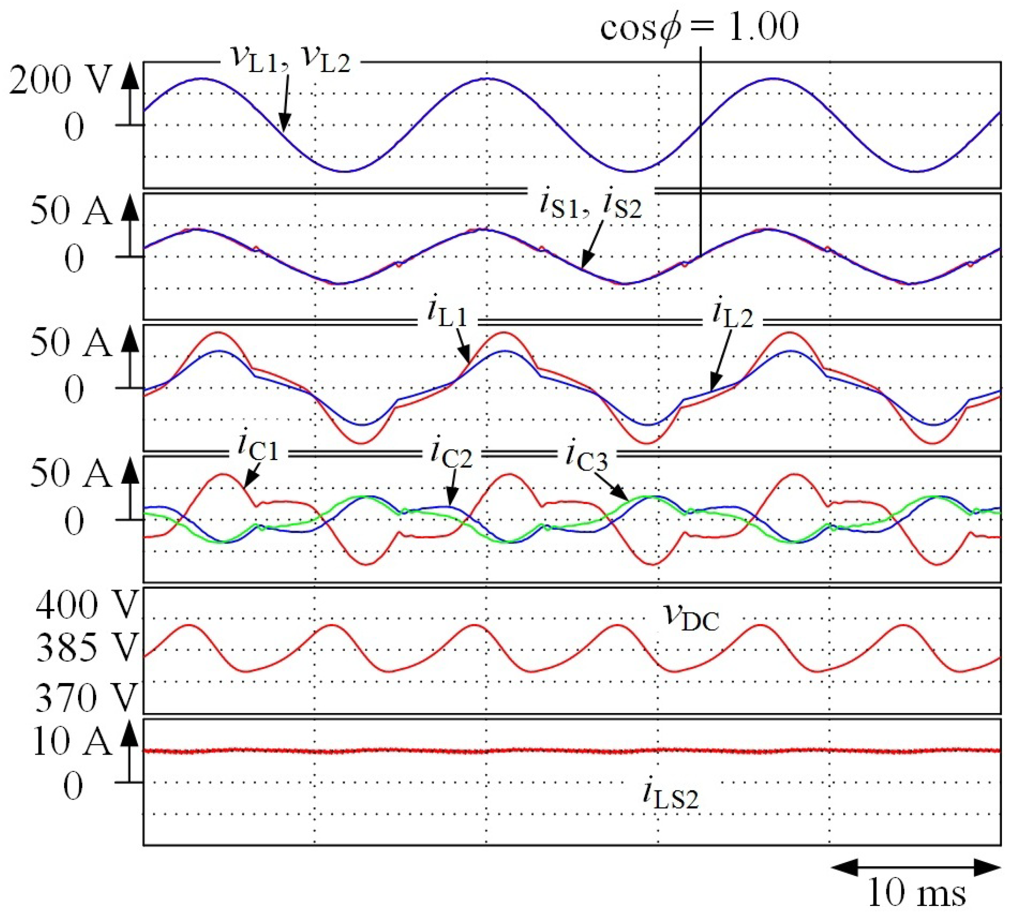
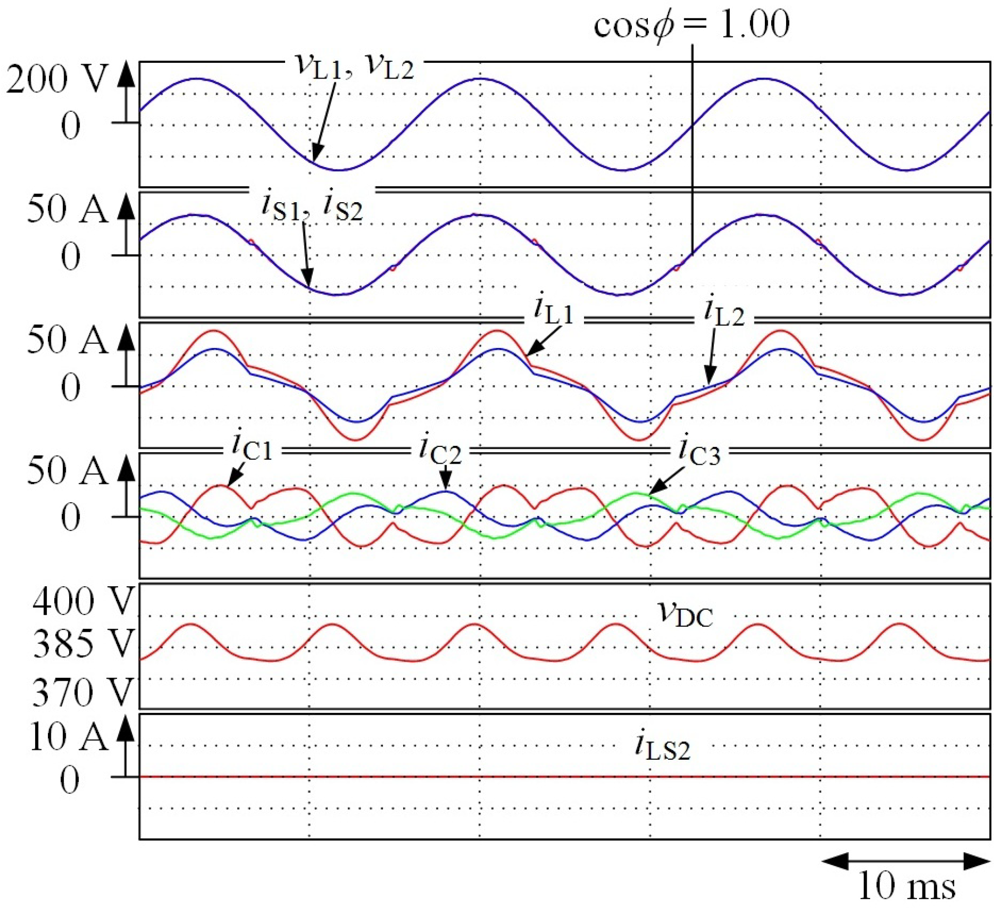
3. Simulation Results
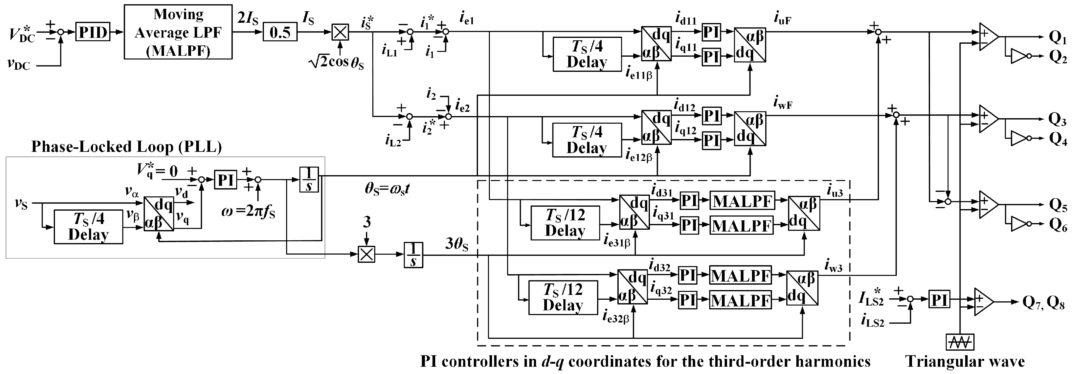
The validity and high practicality of the proposed PI controllers in d-q coordinates for the 3rd harmonic components of the currents in the proposed SC are confirmed by computer simulation using the PSIM software. In the following simulation results, the constants shown in Table 1 are used. The unbalanced ratio between feeders 1 and 2 in SPTWDF is defined as:
Unbalanced ratio = S 1 S 2 S A × 0.5 × 100 [ % ] ,
where S 1 is the apparent power of load 1 in feeder 1, and S 2 is the apparent power of load 2 in feeder 2. S A is the sum of S 1 and S 2 . According to Japanese guidelines, the unbalanced ratio should be less than 40% [12]. Therefore, load conditions in feeders 1 and 2 were decided as shown in Figure 1. Table 1 shows the circuit constants, which are used in the following simulation and experimental results. Additionally, in the simulation and experiments:
  • K P = 0.6, T I = 0.03 s, and T D = 0.01 ms are used in the PID controller of the CDCVC;
  • K P = 0.06 and T I = 8 ms are used in the PI controllers in d-q coordinates for both fundamental and the 3rd harmonic components of the currents; and
  • K P = 0.15 and T I = 3 ms are used in the PI controller for the current feedback of the bidirectional dc-dc converter.
The Ziegler–Nichols ultimate sensitivity method was used to initially decide these parameters, and they were improved by the computer simulation.
Figure 7 shows the simulation results when the SC charges power to the battery with constant battery current control, for the proposed control strategy of Figure 6. The source currents i S 1 and i S 2 are balanced with unity PF even though the load currents i L 1 and i L 2 are unbalanced and distorted. The THD values of i S 1 , i S 2 , i L 1 , and i L 2 are 2.00%, 1.81%, 26.3%, and 23.6%, respectively. In Reference [2], without the current controllers in d-q coordinates for the 3rd harmonic currents, the THD values of i S 1 and i S 2 were 3.92% and 2.50%, respectively. The addition of the current controllers for the 3rd harmonic currents reduces the THD values of i S 1 and i S 2 by 1.92% and 0.69%, respectively.
Figure 8 shows the simulation results when the SC discharges the power from the battery with constant battery current control. The source currents i S 1 and i S 2 are balanced with a unity PF even though the load currents i L 1 and i L 2 are unbalanced and distorted. The THD values of i S 1 and i S 2 are 4.93% and 3.73%, respectively. In Reference [2], without the controllers in d-q coordinates for the 3rd harmonic currents, the THD values of i S 1 and i S 2 were 10.8% and 7.7%, respectively. The addition of these current controllers in reduces the THD values of i S 1 and i S 2 by 5.77% and 2.66%, respectively.
Figure 9 shows the simulation results when the battery v bat is not connected. The bidirectional dc-dc converter consisting of Q 7 and Q 8 is not under operation. Therefore, the SC performs as an active power-line conditioner for a domestic consumer. Balanced and sinusoidal source currents i S 1 and i S 2 are attained. The THD values of i S 1 and i S 2 are 2.97% and 2.30%, respectively. In Reference [2], without the controllers in d-q coordinates for the 3rd harmonic currents, the THD values of i S 1 and i S 2 were 5.51% and 2.94%, respectively. Adding of the current controllers for the 3rd harmonic currents reduces the THD values of i S 1 and i S 2 by 2.54% and 0.64%, respectively. The THD values of i S 1 and i S 2 in Figure 7, Figure 8 and Figure 9 satisfy the regulations [13].

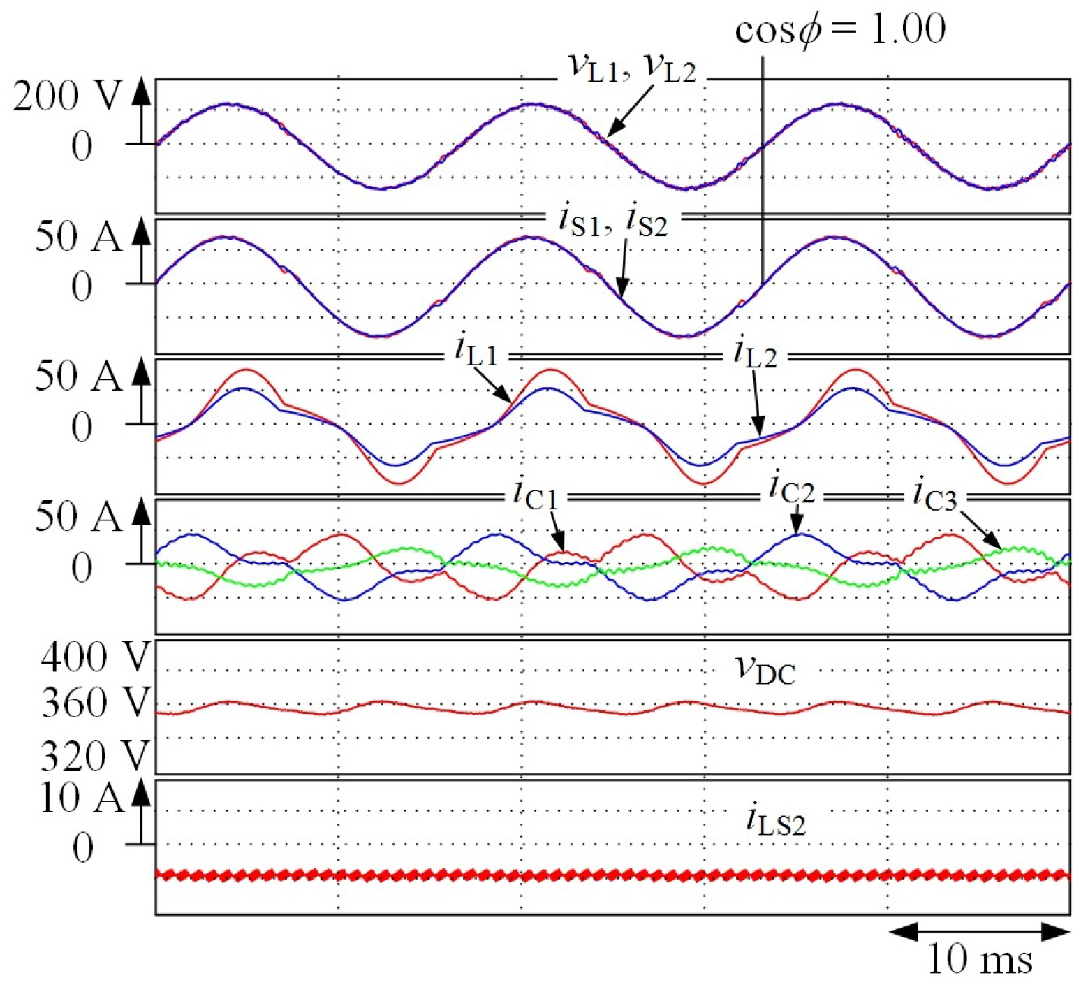
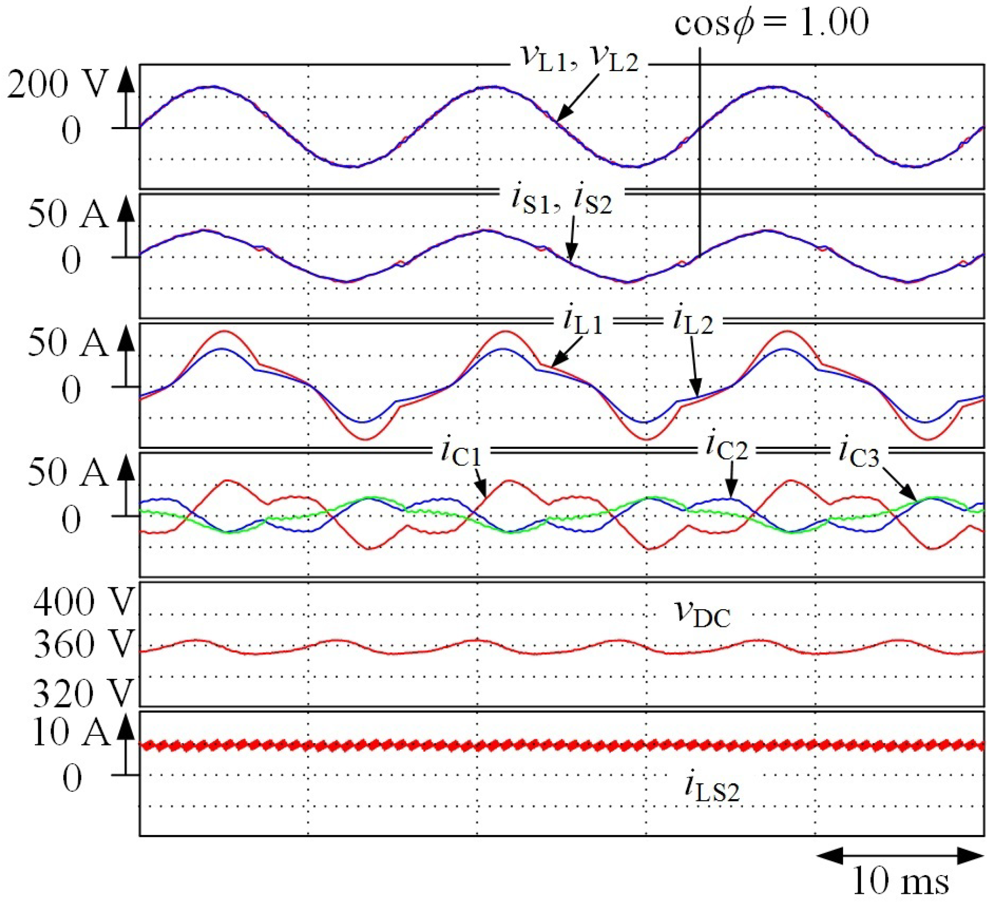
4. Experimental Results

It is difficult to construct an experimental setup for the SC of Figure 1 because of the high-voltage rating on the primary side of the PMDT. A reduced-scale experimental model was, therefore, constructed and tested to show the validity and high applicability of the proposed CDCVC strategy for the SC. Figure 10 shows a block diagram of the constructed reduced-scale prototype experimental setup. The unbalanced ratio in feeders 1 and 2 is 40%. As shown in Figure 10a, a resistor R of 60 Ω is connected in parallel to a capacitor C f 2 under the battery charging operation of the bidirectional dc-dc converter. The charged power, which is from the utility grid, is consumed by the resistor R. A dc power supply (Takasago: HX0300-25) is connected to C f 2 during the battery discharging operation as shown in Figure 10b. The battery voltage V bat is 257 Vdc. The detected voltages and currents v S , v dc , v Cf 2 , i L 1 , i L 2 , i 1 , i 2 , and i LS 2 are fed into a digital signal processor (DSP) (TMS320C6713, 225 MHz) through 12-bit A/D converters. The sampling time T S is 0.107 ms. The reference values i 1 * , i 2 * , and i 3 * for the source currents i S * , i S 1 * , and i S 2 * are calculated by Equation (9). With the DSP, the dc-capacitor voltage v dc is controlled. The output currents i C 1 , i C 2 , and i C 3 of the SC, formed by the three-leg PWM rectifier, are controlled with current feedback control in d-q coordinates for both the fundamental and 3rd harmonic components. The output current i LS 2 of the bidirectional dc-dc converter is also controlled by the DSP. The circuit constants shown in Table 1 are used in the following experimental results.
Figure 11 shows the experimental results when the SC discharges the power from the battery with constant battery current control, for the SC model of Figure 10 with the proposed control strategy of Figure 6. The source currents i S 1 and i S 2 are balanced with a unity PF even though the load currents i L 1 and i L 2 are unbalanced and distorted. The THD values of i S 1 , i S 2 , i L 1 , and i L 2 are 4.44%, 3.05%, 24.1%, and 24.2%, respectively. In Reference [2], without current controllers for the 3rd harmonic currents, the THD values of i S 1 and i S 2 were 7.49% and 5.13%, respectively. The addition of the current controllers for the 3rd harmonic currents reduces the THD values of i S 1 and i S 2 by 3.05% and 2.08%, respectively.
Figure 12 shows the experimental results, when the SC discharges power from the battery with constant battery current control. The source currents i S 1 and i S 2 are balanced with unity PF, even though the load currents i L 1 and i L 2 are unbalanced and distorted. The THD values of i S 1 and i S 2 are 8.60% and 6.60%, respectively. In Reference [2], without the current controllers for the 3rd harmonic currents, the THD values of i S 1 and i S 2 were 17.0% and 10.2%, respectively. The THD values of i S 1 and i S 2 are improved by 8.40% and 3.60%, respectively, with the controllers in d-q coordinates for the 3rd harmonic currents.
Figure 13 shows the experimental results, when the battery v bat is not connected. The source currents i S 1 and i S 2 are balanced with unity PF, even though the load currents i L 1 and i L 2 are unbalanced and distorted. The THD values of i S 1 and i S 2 are 6.00% and 4.24%, respectively. In Reference [2], without the current controllers for the 3rd harmonic currents, the THD values of i S 1 and i S 2 were 9.83% and 5.58%, respectively. The THD values of i S 1 and i S 2 are improved by 3.83% and 1.34%, respectively.
The THD values of i S 1 and i S 2 in Figure 11, Figure 12 and Figure 13 satisfy the regulations [13]. The experimental results of Figure 11, Figure 12 and Figure 13 agree well with the simulation results of Figure 7, Figure 8 and Figure 9. The authors conclude that the addition of the PI controllers in d-q coordinates for the 3rd harmonic currents reduces the THD values of i S 1 and i S 2 .

5. Conclusions

This paper has introduced an improvement in the harmonic compensation performance of the previously proposed SC with a CDCVC strategy for EVs in SPTWDFs. A controller for the 3rd harmonic currents in d-q coordinates is added to the current controller for the fundamental component in d-q coordinates of the previously proposed control strategy for the SC. Adding the controller for the 3rd harmonic currents improves the harmonic compensation performance on the source side. Harmonic current compensation with the previously proposed CDCVC strategy for SC has been briefly introduced. Then, the basic principles of the proposed controller for the 3rd harmonic currents in d-q coordinates have been discussed in detail. It has been shown that synchronization of the current controllers in d-q coordinates for both the fundamental and 3rd harmonic components is required. The switching frequency of a three-leg PWM rectifier with a bidirectional dc-dc converter has been determined based on the synchronization of the current controllers. Simulation and experimental results have demonstrated that balanced and sinusoidal source currents with unity PF are obtained both during battery charging and discharging operations in EVs, thus improving the harmonic compensation performance of the SC compared to the previously proposed scheme. Experimental results also have demonstrated that the THD values of the source currents are improved by 8.4% and 3.6% with the proposed current controller for 3rd harmonic currents in d-q coordinates, when the SC is under the battery discharging, for example.

Author Contributions

K.N. significantly contributed to demonstrate the basic principle of the constant dc-capacitor voltage-control-based strategy and contributed to demonstrate the validity and practicability of the proposed control strategy by the reduced-scale experimental setup. F.I. also significantly contributed to implement the digital computer simulation and helped with the writing of this paper. Y.O. contributed to help the construction on the reduced-scale experimental setup. T.T. proposed the control strategy and helped with the writing of this paper. H.Y. and M.O. were responsible for guidance and key suggestions.

Funding

This work was supported by JSPS KAKENHI Grant Number JP16K06225.

Conflicts of Interest

The authors declare no conflict of interest.

References

  1. Tanaka, T.; Sekiya, T.; Tanaka, H.; Okamoto, M.; Hiraki, E. Smart charger for electric vehicles with power quality compensator on single-phase three-wire distribution feeders. IEEE Trans. Ind. Appl. 2013, 49, 2628–2635. [Google Scholar] [CrossRef]
  2. Ikeda, F.; Yamada, H.; Tanaka, T.; Okamoto, M. Constant dc-capacitor voltage-control-based harmonics compensation strategy of smart charger for electric vehicles in single-phase three-wire distribution feeders. Energies 2017, 10, 13. [Google Scholar] [CrossRef]
  3. Akagi, H.; Kanazawa, Y.; Nabae, A. Instantaneous reactive power compensators comprising switching devices without energy storage components. IEEE Trans. Ind. Appl. 1984, 3, 625–630. [Google Scholar] [CrossRef]
  4. Peng, F.Z.; Ott, G.W.; Adams, D.J. Harmonic and reactive power compensation based on the generalized instantaneous reactive power theory for the three-phase four-wire systems. IEEE Trans. Power Electron. 1998, 13, 1174–1181. [Google Scholar] [CrossRef]
  5. Geddada, N.; Karanki, S.B.; Mishra, M.K.; Kumar, B.K. Modified four leg DSTATCOM topology for compensation of unbalanced and nonlinear loads in three phase four wire system. In Proceedings of the 2011 14th European Conference on Power Electronics and Applications, Birmingham, UK, 30 August–1 September 2011; pp. 1–10. [Google Scholar]
  6. Dixon, J.W.; Garcia, J.J.; Moran, L. Control system for three-phase active power filter which simultaneously compensates power factor and unbalanced loads. IEEE Trans. Ind. Electron. 1995, 42, 636–641. [Google Scholar] [CrossRef]
  7. Abellan, A.; Garcera, G.; Pascual, M.; Figueres, E. A new current controller applied to four-branch inverter shunt active filters with UPF control method. In Proceedings of the 2001 IEEE 32nd Annual Power Electronics Specialists Conference, Vancouver, BC, Canada, 17–21 June 2001; Volume 3, pp. 1402–1407. [Google Scholar]
  8. Haque, M.T. Single-phase pq theory for active filters. In Proceedings of the 2002 IEEE Region 10 Conference on Computers, Communications, Control and Power Engineering (TENCOM’02), Beijing, China, 28–31 October 2002; Volume 3, pp. 1941–1944. [Google Scholar]
  9. Arruda, L.N.; Silva, S.M. PLL structures for utility connected systems. In Proceedings of the 36th IAS Annual Meeting, Conference Record of the 2001 IEEE Industry Applications Conference, Chicago, IL, USA, 30 September–4 October 2001; pp. 2655–2660. [Google Scholar]
  10. Silva, S.M.; Lopes, B.M.; Campana, R.P.; Bosventura, W.C. Performance evaluation of PLL algorithms for single-phase grid-connected systems. In Proceedings of the 39th IAS Annual Meeting, Conference Record of the 2004 IEEE Industry Applications Conference, Seattle, WA, USA, 3–7 October 2004; pp. 2259–2263. [Google Scholar]
  11. Zhang, R.S. Control of Single Phase Power Converter in d-q Rotating Coordinates. U.S. Patent 6,621,252 B2, 16 September 2003. [Google Scholar]
  12. Japan Electric Association. Indoor Wiring Guidelines; JESC E0005; Japan Electric Association: Tokyo, Japan, 2005; p. 32. (In Japanese) [Google Scholar]
  13. IEC 61000-3-4. Raprort Technique Technical Report; International Electrotechnical Commission: Geneva, Switzerland, 1998. [Google Scholar]
Figure 1. Power circuit diagram of the previously proposed smart charger (SC).
Energies 11 01604 g001
Figure 2. Control circuit diagram of the previously proposed constant dc-capacitor voltage-control (CDCVC) strategy.
Energies 11 01604 g002
Figure 3. Control circuit diagram for the SC in Figure 1, if the single-phase pq theory is applied.
Energies 11 01604 g003
Figure 4. Simulation results for the previously proposed SC during a battery discharging operation from Reference [2].
Energies 11 01604 g004
Figure 5. Spectra of the source currents from the same simulation as Figure 4.
Energies 11 01604 g005
Figure 6. Proposed control circuit diagram for the SC of Figure 1.
Energies 11 01604 g006
Figure 7. Simulation results for the SC in Figure 1 during a battery charging operation.
Energies 11 01604 g007
Figure 8. Simulation results during a battery discharging operation for the SC in Figure 1.
Energies 11 01604 g008
Figure 9. Simulation results for the SC in Figure 1 without the battery connected; when the SC performs as an active power-line conditioner.
Energies 11 01604 g009
Figure 10. Block diagram of the constructed experimental model for the SC in Figure 1.
Energies 11 01604 g010
Figure 11. Experimental results during battery charging for the SC in Figure 10.
Energies 11 01604 g011
Figure 12. Experimental results during battery discharging for the SC in Figure 10.
Energies 11 01604 g012
Figure 13. Experimental results for the SC in Figure 10 without the battery connected.
Energies 11 01604 g013
Table 1. Circuit Constants for following simulation and experimental results.
ItemSymbolValue
SimulationExperiment
Filter inductor for three-leg PWM rectifier L f 1 0.46 mH
Filter capacitor for three-leg PWM rectifier C f 1 10.4 μ F
Switching inductor for three-leg PWM rectifier L S 1 1.0 mH
dc capacitor C DC 2700 μ F
dc-capacitor voltage V DC * 385 Vdc360 Vdc
Switching inductor for dc-dc converter L S 2 4.4 mH
Filter capacitor for dc-dc converter C f 2 1000 μ F
Battery voltage V bat 360 Vdc257 Vdc
Inductor current for dc-dc converter I LS 2 * 5 Adc4.29 Adc
Internal resistance of batteryr72 m Ω
Switching frequency f SW 9.36 kHz
Dead time T d 3.5 μ s

