AC Flashover Performance of 10 kV Rod-Plane Air-Gapped Arresters under Rain Conditions


State Key Laboratory of Disaster Prevention & Reduction for Power Grid Transmission & Distribution Equipment, State Grid Hunan Electric Power Corporation Disaster Prevention & Reduction Center, Changsha 410007, China
*
Author to whom correspondence should be addressed.
Energies 2018, 11(6), 1563; https://doi.org/10.3390/en11061563
Submission received: 24 May 2018
/
Revised: 7 June 2018
/
Accepted: 12 June 2018
/
Published: 14 June 2018
Abstract
:According to operational experience of power systems, the outdoor insulation strength can be reduced due to the effect of rain. Till now, little work has been done to investigate the flashover performance of air gapped arresters under rain conditions. Therefore, in this paper, experiments were carried out and the AC flashover performance of 10 kV arresters with different air gap structures was studied. The experimental results show that, for the tested arresters, the flashover current mainly flows through the air gaps and zinc oxide varistors under rain conditions. It is also confirmed that the flashover voltages decrease with the increasing of rain intensity and conductivity. In the windward direction, the wind can distort the water streams between the air gaps and rise the flashover voltages. In the leeward direction, if the rod electrode is beyond the range of the plane electrode, the flashover voltage researches the smallest value when the wind speed is 4 m/s. Analysis and discussions have been done to explain the experimental results, and the research in this paper may provide reference to improve the flashover performance of air gapped arresters under rain conditions.
1. Introduction
With the fast development of power systems in China, some new problems have been found, and one of them is heavy rain. According to operational experience, electric accidents caused by heavy rain have been frequently reported [1,2,3,4,5]. Therefore, it is of great significance to study the rain effects on the insulation performance of the power systems.
Studies have been carried out to investigate the influence of rain on the breakdown and flashover performance in the power systems. The rain effects on switching impulse spark-over voltage of different air gaps were studied [6,7,8]. In [6,7], full-scale experimental setups were carried out, and the breakdown performances of phase-to-ground and phase-to-phase insulation with different gap lengths in dry and wet conditions have been compared. The results indicated that the water drops in the shielding ring should be the main reason for the decrease in breakdown voltage under rain conditions [7]. The effects of rain on the breakdown characteristics of conductor-to-tower air gaps under power frequency voltages were studied in [8,9], and the breakdown characteristics of rod to plane short air gaps under different voltages (switching [10], DC [11], AC [12]) have been investigated. It has been found that rain drops can reduce the insulation strength of the power systems under different kinds of applied voltages. Flashover performance of insulators under rain conditions was studied in [13,14], and the effects of rain on the self-cleaning and flashover performance of insulators have been studied in [4]. The results show that, rational sheds structure can improve the flashover voltage of insulators under rain conditions.
According to the existing studies, the breakdown and flashover performance of air gaps and insulators under rain conditions have been studied by scholars. However, the structure of the air gapped arresters is more complicate than air gaps and insulators, which have air gaps, silicon rubber sheds and zinc oxide (ZnO) varistors contained in the arresters. Until now, not much work has been done to study the flashover performance of air gapped arresters. What’s more, it has been confirmed that the insulation performance of the electric equipment can be reduced with the increase of rain conductivity and rain intensity, but the wind effects on the rain flashover performance of the air gapped arresters has not been studied.
In view of the above, experimental investigations about the AC flashover performance of 10 kV air gapped arresters have been carried out in this paper. The effects of rain intensity, rain conductivity, and wind on the air gapped arresters’ flashover characteristics are studied. Finite element methods are applied to study the electric field distributions of the tested specimens, and analysis has been made to explain the experimental results. The studies in this paper can give help to the improvement of insulation performance of air gapped arresters under rain conditions. This paper is organized as follows:
- Firstly, the test facilities, specimens and procedures are introduced, compared with the existing work, the rain flashover characteristics of the air gapped arresters are studied, whose structure and flashover process is more complicated than the air gaps and insulators in the existing papers.
- Secondly, the flashover characteristics of the test specimens are obtained and analyzed. The effects of rain intensity and conductivity on the flashover performance of the test species were studied. Compared with the existing studies, the effects of wind speed and direction have been studied.
- Finally, conclusions are made, and some suggestions have been made for the design and type selection of air gapped arresters.
2. Test Facilities, Specimens and Procedures
2.1. Test Facilities
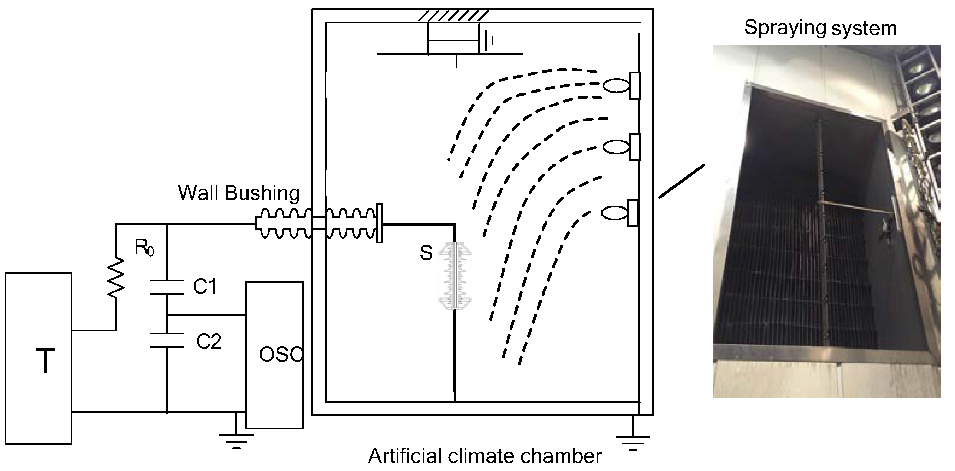
The experimental test circuit used in this paper is presented in Figure 1. The power is supplied by an 100 kV/320 kVA test transformer and leaded in through a wall bushing, R0 is the protective resistor (R0 = 5000 Ω), and the applied voltage is measured by a capacitive voltage divider (C1 = 10 pF, C2 = 100 pF). As shown in Figure 1, S represents the test specimen, the high voltage terminal of S is connected to the output of the test transformer, and the low voltage terminal of S is grounded.
The rain flashover tests were carried out in a multi-function artificial climate chamber in the State Grid Corporation of Hunan in Changsha, China. The artificial climate chamber has a diameter of 9 m and a height of 12 m. The spraying system in Figure 1 consists of more than 10 fog nozzles, and the wind velocity regulating system is composed of more than 10 fans placed in a tapering box with a diffusing honeycomb panel. The atmospheric parameters were measured by means of the PTU200 pressure-temperature-humidity transmitter produced by Vaisala Oyj Company of Finland and the measured deviations of temperature, relative humidity, and atmospheric pressure are respectively ±0.2 °C, ±1% RH and ±0.03 kPa. The rain intensity was measured with the JFZ-01 digital hyetometer in the high voltage test hall and the WXT520 atmospheric transmitter produced by Vaisala Company in the field tests. The rain conductivity was measured by the DD-810E conductivity meter. In field tests, wind velocity was recorded with the AVM-03 anemometer produced by the TES Company of Taiwan. These facilities can meet the requirements for rain flashover tests [15,16].
2.2. Test Specimens
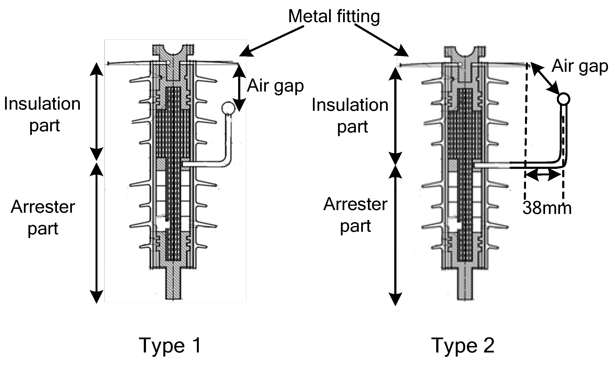
The test specimens consist of 2 types of 10 kV air gapped arresters, and the profiles of the test specimens are presented in Figure 2. The test specimens have two parts: the insulation part and the arrester part. The insulation part is made of epoxy resin and connected with an air gap in parallel. The arrester part has ZnO varistors contained in it. Both the insulation part and arrester part are covered by silicone rubber sheds. For the test specimens shown in Figure 2, the structure height is 395 mm, the creepage distance of the insulation part and arrester part is 320 mm, the sheds distance is 32 mm, and the sheds diameters are 132/102 mm. The diameter of the metal fitting (plane electrode) is 200 mm. The rod electrode of type 1 is just under the edge of the plane metal fitting while the rod electrode of type 2 is 50 mm beyond the plane electrode. The distances between the plane and rode electrode of type 1 and type 2 are all 55 mm.
The air gapped arresters in Figure 2 are used to protect distribution lines from lightning over-voltages. However, under rain conditions, the arresters in Figure 2 may suffer rain flashovers. Therefore, a series of flashover experiments were carried out to investigate the rain flashover characteristics of the specimens.
2.3. Test Procedures
The rain flashover tests were carried out in the climate chamber. Before tests, the specimens were carefully cleaned up and dried at room temperature. After that, the test specimens were installed vertically in the chamber. As shown in Figure 1, the top section was connected to the high voltage lead and the bottom was grounded; in the experiments, a 1 m long conductor is connected to the high voltage terminal of the test specimens to be more realistic. When the wind speed is 0 m/s, the rain drops fall almost vertically on the test specimens.
In artificial tests, according to the operational experience [3], the rain intensity I and the rain conductivity γ ranged from 0–14 mm/min and 500–2000 μS/cm respectively, the wind speed ranged from 0–8 m/s. The precipitation rate, the angle of rain spraying of the artificial rain were measured and checked according to the standardized procedure [15,16,17].
In all of the tests, step up method was used to investigate the AC flashover voltage of rod-plane air gapped arresters in rain conditions [12]. The rate of voltage rise was about 3–4 kV/s in artificial tests. The number of experiments was at least 10, of which the standard deviation was within 5%. So as to ensure the validity of test data, the rain intensity was verified every 5 min. The breakdown voltages with a standard deviation more than 5% were ignored. The AC flashover voltage of the test specimens equals to the mean value of the tested breakdown voltage.
3. Test Results and Analysis
Rain flashover tests were carried out in the artificial climate chamber, and the test results are given and analyzed in this section, where I is the rain intensity, mm/min; γ is the rain conductivity corrected to 20 °C, μS/cm; v is the wind speed, m/s.
3.1. Effects of Rain Conductivity
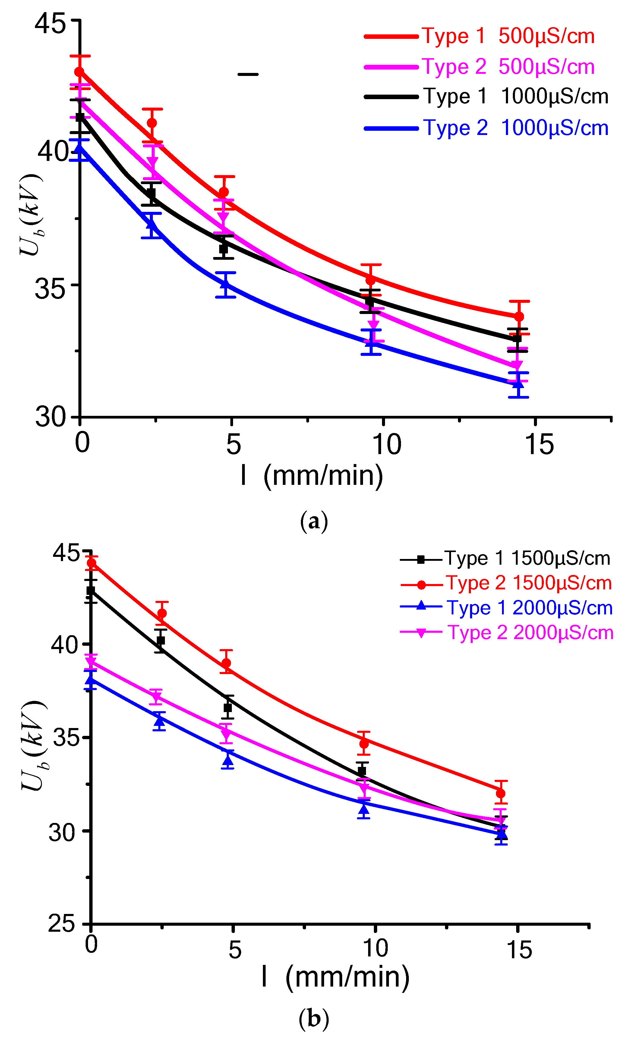
According to the experimental results, when wind speed v = 0 m/s, the relationship between flashover voltage and rain conductivity is shown in Figure 3, from which it can be known that, with the increase of rain conductivity, the flashover voltage decreases, and the max decent degree is 5.8%.
According to the studies in [18,19], the influence of the water conductivity can be summarized as follows: firstly, a higher conductivity can enhance the local field at the head of the avalanche; secondly, the electrons at the head of the avalanche at the positive side of the drop are faster absorbed by the drop surface and are therefore less efficient in producing photons for secondary avalanches that could enhance the space charge of the aborted streamer.
3.2. Effects of Rain Intensity
When the wind speed is 0 m/s, the effects of rain intensity on the flashover performance are shown in Figure 4. As shown in the figure, with the increasing of rain intensity, the flashover voltage decreases less than 10%.
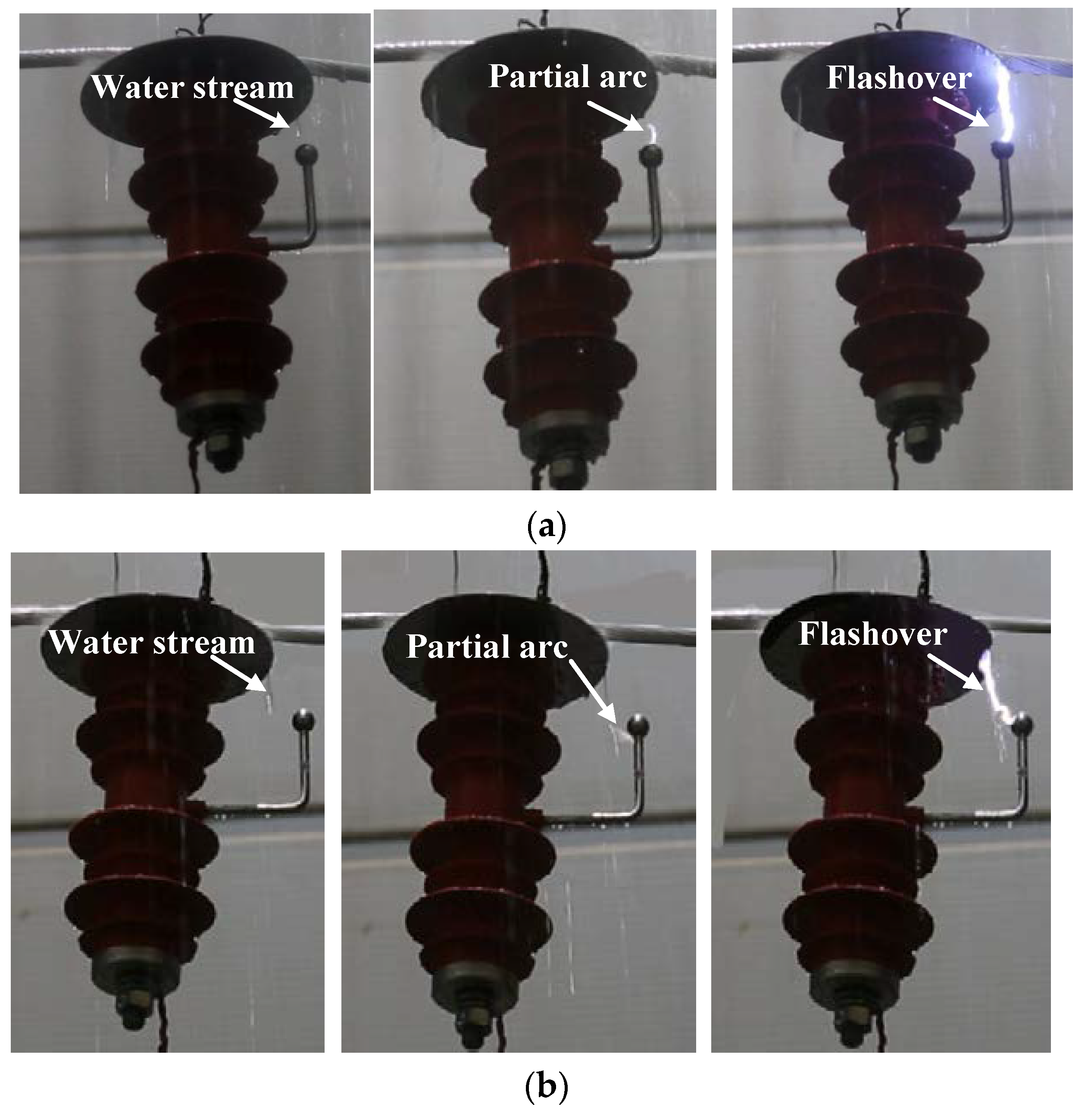
Figure 5 shows the rain flashover process of the test specimens, as shown in the figure, when v = 0 m/s, I = 9.6 mm/min. Water streams existed under the metal fittings. At the beginning of the flashover process, local arcs appeared between the water stream and the lower electrode, as the flashover process went on, the local arc develops along the water stream and the air gaps of the arresters. From Figure 5, it can be confirmed that, under normal working conditions, the AC voltage applied on the 10 kV arresters is 5.8 kV per phase, flashover will not happen under rain conditions. However, when over-voltages are applied on the arresters, the air gaps are broken down and the ZnO varistors work in non-linear section [20,21], the flashover path develops through the arc gaps and ZnO varistors of the arresters and no flashover arc appears on the surface of the arrester part.
In order to explain the effects of the rain intensity, the finite element method is applied to study the electric field distributions of the test specimens under rain conditions in the Ansoft software. The simulation model is shown in Figure 6a, and the simulation parameters are obtained from [22,23,24], the relative permittivity of the ZnO varistor, silicone rubber sheds and epoxy resin are 800, 3 and 6 respectively. The metal fitting is set to be ideal conductor. According to the experimental flashover process in Figure 5 and the simulation model in [12], the following assumptions are made when building the calculation model:
(1). When v = 0 m/s, no rain droplets exist within the scope of metal fitting, under the edges of the metal fitting, there are water stream and rain droplets between the metal fitting and rod electrode, the length of the water stream is set to be 20 mm long, and the rain droplets is 4–6 mm [25].
(2). The test specimens are symmetrical and can be built in a 2-D model. The metal plane of the test specimen is connected to the high-voltage terminal, and the other side of the test specimen is grounded.
(3). The simulation region is a 3 m × 3 m rectangle, and the test specimen is in the center of the simulation region. The lower boundary (ground plane) of the simulation region is set to 0 V, and the other boundaries are set to be infinite boundaries [26].
(4). The operating voltage frequency of the test specimens is 50 Hz, according to [26], the 50 Hz AC electric field is quasi-static field and can be considered as static field approximately. Applying a 5.8 kV DC voltage (root mean square value of phase voltage in 10 kV system) on the high voltage terminal, and the electric field distribution is obtained and shown in Figure 6b,c.
As shown in Figure 6b,c, it can be confirmed that, due to the rain effects, the voltage applied on the arrester part is very small, and the air gap between the electrodes withstands most of the applied voltage. Thus, the electric field in the air gap between the water streams, rain droplets and electrodes is much higher. With the increase of rain intensity, the water streams grow longer, which makes the air gap shorter and easier to be breakdown.
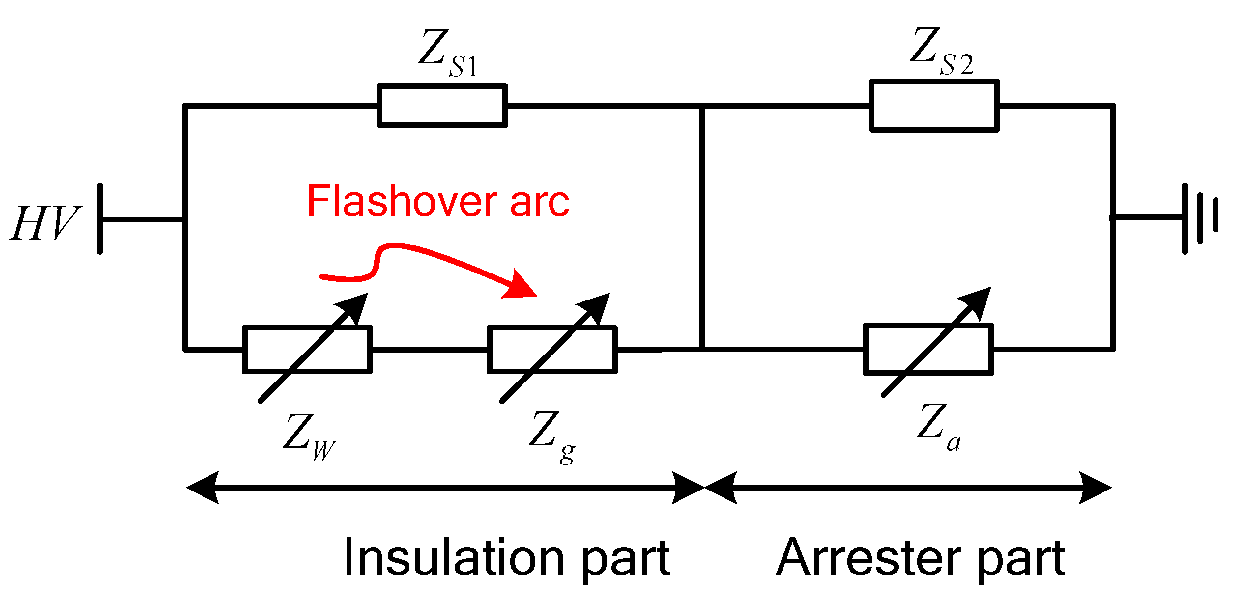
According to the analysis above, based on the flashover model built in [27,28,29], the equivalent circuit of the arresters under rain conditions is built and shown in Figure 7, where ZS1 and ZS2 are the surface equivalent impedances of the insulation part and arrester part. ZW is the impedance of the water film, Zg is the impedance of the air gap, and Za is the impedance of the ZnO varistors.
Under rain conditions, according to the equivalent circuit model shown in Figure 7, water streams exist under the edge of the metal fitting, and the insulation part withstands most of the applied voltage. When the applied voltage exceeds the air gap breakdown voltage, flashover arc appears, ZW, Zg become much lower and the arrester part withstand most of the applied voltage. According to the experimental results above, as the air gap breakdown voltage is always higher than the rated voltage of the arrester part, when the flashover occurs, Za becomes much smaller, and the flashover current mainly flows the ZnO varistors of the arrester part. So, as shown in Figure 5, the flashover arc appears on the insulation part and not observed on the arrester part.
3.3. Effects of Wind
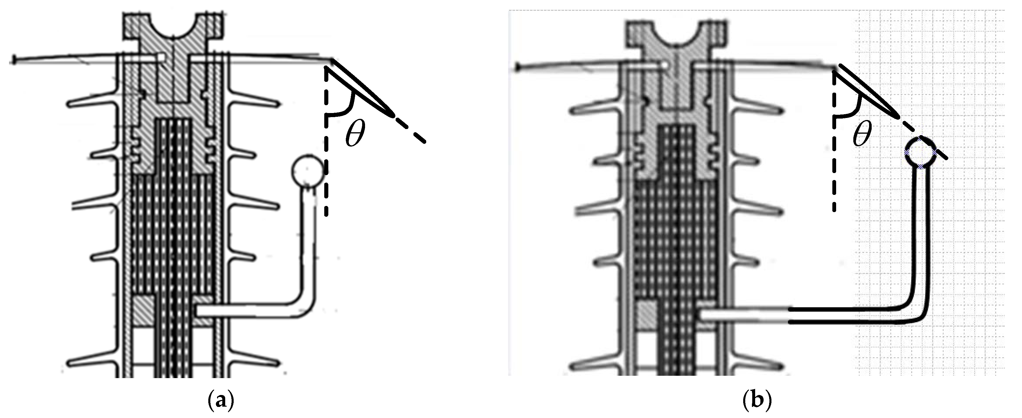
When I = 9.6 mm/min and γ = 500 μS/cm, the effects of wind on the flashover voltage of the test specimens is shown in Figure 8. It can be seen that, for the type 1 specimen, the flashover voltage increases in both windward and leeward direction. For the type 2 specimen, when the air gap is in a windward direction, the flashover voltage increases with the increasing of wind speed, when the air gap is in a leeward direction, the flashover voltage decreases before 4 m/s, as the wind speed continues to increase, the flashover voltage increases.
When the wind speed is 4 m/s, the flashover path of the test specimens are shown in Figure 9, compared with Figure 5, it can be known that, in the windward direction, because of the wind effects, the water streams were broken. ZW and Zg become larger, leading to higher flashover voltages, for type 1, a part of the flashover arc develops along the silicon rubber sheds. However, in the leeward direction, the flashover paths were influenced little by the wind.
According to Section 3.3, the flashover voltage is largely dependent on the water stream and air gap length. In this paper, Figure 10 is given to explain the wind effects on the flashover voltage and flashover path in Figure 8 and Figure 9. In Figure 10, θ means the angle between the water film and vertical line, in the windward direction, when the wind speed increases, the air gaps between the lower electrode and water stream become larger, and the flashover voltage of both type 1 and type 2 increases. In the leeward direction, for type 1, the air gap between the electrodes becomes larger when the wind speed increases, for type 2, when the wind speed is about 4 m/s, the length of the air gap and the flashover voltage reach the smallest value. What’s more, as observed in the experimental tests, when the wind speed increases, the water streams may become shorter or even broken by wind. This is why the flashover voltage decreases with the increasing of wind speed when v > 4 m/s.
From the test results, it can be seen that the wind has a greater influence when the rod electrode is beyond the metal plane (type 2). However, it is also confirmed that, when the rod electrode is too near to the silicon rubber sheds, it is easier for flashover arcs to develop on the silicon rubber sheds and lead to aging and damage of the insulation part (type 1). So, in order to improve the rain flashover characteristics of the test arresters, it is suggested to use the rod structure of type 2 and enlarge the metal plane diameter to a proper extent that can be easily produced and maintained.
4. Conclusions
In this paper, a series of tests were carried out to study the rain flashover performance of 2 types of air gapped arresters, from which the following conclusions can be made:
- (1)
- Under rain conditions, the air gap withstands most of the applied voltage and the flashover path develops through the water stream, air gap, and ZnO varistors. It is confirmed that, compared with insulators, no flashover happens on the surface of the insulation part.
- (2)
- As the rain intensity and conductivity changes, the rain flashover voltage may decrease up to 10%. Compared with rain intensity and conductivity, the influence of wind speed is much higher, the flashover voltage may increase up to 30%. When the air gap is in the windward direction, the flashover voltage becomes higher due to the wind effects. When the air gap is in the leeward direction, the flashover voltage of type 1 increases with the increasing of wind speed, while the flashover voltage reaches the smallest value when the wind speed is 4 m/s.
- (3)
- For the test specimens studied in this paper, the wind has a greater influence when the rod electrode is beyond the metal plane, while the flashover arcs may develop along the silicon rubber sheds and lead to aging and damage of the insulation part when the rod electrode is too near to the silicon rubber sheds. Thus, in order to obtain better rain flashover performance, it is suggested to use the rod structure of type 2 and enlarge the metal plane diameter to a proper extent that can be easily produced and maintained.
Author Contributions
P.X. carried out the experiments, analyzed the test results, and wrote this paper. J.L. gave input to the analysis of test results. J.H., Z.J. and Z.F. carried on the experimental set up.
Acknowledgments
The authors gratefully acknowledge the contributions of all members of the external insulation research team in State Grid Hunan Electric Power Corporation for their work on this paper.
Conflicts of Interest
The authors declare no conflict of interest.
References
- Zhang, C.Y.; Meng, X.B.; Zhang, F.Z. Research on the DC rain flashover mechanism of polluted post insulators. Proc. CSEE 2014, 34, 1481–1489. (In Chinese) [Google Scholar]
- Wei, X.X.; Li, J.P.; Chu, J.W.; Xia, G.L.; Chen, W. Application of Composite Insulators and Analysis of Rain Flashover in Converter Stations. High Volt. Eng. 2017, 43, 3958–3963. (In Chinese) [Google Scholar]
- Deng, W.T.; Zhang, B.; Wang, T.; Li, L. Rain Flashover Analysis of HVDC Reactor Bushing Using Rainwater-Air Mixture Model. Trans. China Electro Tech. Soc. 2017, 32, 211–217. (In Chinese) [Google Scholar]
- Jiang, Z.D.; Jiang, X.L.; Zhang, Z.J.; Guo, Y.J.; Li, Y.F. Investigating the Effect of Rainfall Parameters on the Self-Cleaning of Polluted Suspension Insulators: Insight from Southern China. Energies 2017, 10, 601. [Google Scholar] [CrossRef]
- Huang, S.L.; Liu, Y.P.; Chen, S.S.; Zhou, G.Y.; Zhuang, W.B. Corona Onset Characteristics of Bundle Conductors in UHV AC Power Lines at 2200 m Altitude. Energies 2018, 11, 1047. [Google Scholar] [CrossRef]
- Rizk, F.A.M. Influence of rain on switching impulse sparkover voltage of large-electrode air gaps. IEEE Trans. Power Appar. Syst. 1976, 95, 1394–1402. [Google Scholar] [CrossRef]
- Rizk, F.A.M. Electrical resistance of an insulating surface under artificial rain. Proc. Inst. Electr. Eng. 1974, 121, 154–160. [Google Scholar] [CrossRef]
- Hu, Y.; Wang, L.N.; Liu, K.; Shao, G.W.; Liu, T.; Hu, J.X. Research of Effect of Wind-Blown Rain on Power Frequency Flashover Characteristic of Conductor-Tower Air Gap. In Proceedings of the 2009 Asia-Pacific Power and Energy Engineering Conference, Wuhan, China, 27–31 March 2009. [Google Scholar]
- Zhou, C.; Yin, J.Q.; Yi, B. Large Swing Behavior of Overhead Transmission Lines under Rain-Load Conditions. Energies 2018, 11, 1092. [Google Scholar] [CrossRef]
- Jiang, X.L.; Xie, Y.B.; Yuan, Y.; Shu, L.C.; Zhang, Z.J. Positive switching impulse discharge performance of rod-plane short air gap under rain conditions. IET Sci. Meas. Tech. 2015, 9, 744–750. [Google Scholar]
- Jiang, X.L.; Yuan, Y.; Bi, M.Q.; Du, Y.; Ma, J.G. DC positive discharge performance of rod-plane short air gap under rain conditions. IEEE Trans. Dielectr. Electr. Insul. 2013, 20, 104–111. [Google Scholar] [CrossRef]
- Jiang, X.L.; Yuan, Y.; Bi, M.Q.; Du, Y.; Ma, J.G. AC breakdown performance and voltage correction of rod-plane short air gap under rain conditions. IEEE Trans. Dielectr. Electr. Insul. 2013, 20, 515–523. [Google Scholar] [CrossRef]
- Zhang, C.Y.; Wang, L.M.; Guan, Z.C. Investigation of DC discharge behavior of polluted porcelain post insulator in artificial rain. IEEE Trans. Dielectr. Electr. Insul. 2016, 23, 331–338. [Google Scholar] [CrossRef]
- Tzimas, A.; Rowland, S.M.; Barrett, J. The influence of surface ageing features of insulators on wet flashover performance. In Proceedings of the 2010 Annual Report Conference on Electrical Insulation and Dielectric Phenomena, West Lafayette, IN, USA, 17–20 October 2010. [Google Scholar]
- Zhang, C.Y.; Wang, L.M.; Guan, Z.C.; Zhang, F.Z. Pollution flashover performance of full-scale ±800 kV converter station post insulators at high altitude area. IEEE Trans. Dielectr. Electr. Insul. 2013, 20, 717–726. [Google Scholar] [CrossRef]
- GB/T 775.2-2003. Test Method for Insulators Part 2: Electrical Test Methods; China Electrical Equipment Industry Association, CEEIA, Inc.: Beijing, China, 2003.
- IEC 60507. Artificial Pollution Tests on High-Voltage Insulators to be Used on A.C. Systems; International Electrotechnical Commission: Geneva, Switzerland, 1991.
- Boussaton, M.P.; Coquillat, S.; Chauzy, S.; Georgis, J.F. Influence of water conductivity on micro-discharges from raindrops in strong electric fields. In Proceedings of the 12th International Conference on Atmospheric Electricity, Versailles, France, 9–13 Jun 2003. [Google Scholar]
- Jiang, X.L.; Wang, Q.L.; Zhang, Z.J.; Hu, J.L.; Hu, Q.; Zhu, C. Ion Migration in the Process of Water Freezing under Alternating Electric Field and Its Impact on Insulator Flashover. Energies 2017, 11, 61. [Google Scholar] [CrossRef]
- Lu, J.Z.; Xie, P.K.; Jiang, Z.L.; Fang, Z.; Wu, W. Voltage Distribution and Flashover Performance of 220 kV Composite Insulators under Different Icing Conditions. Energies 2018, 11, 632. [Google Scholar] [CrossRef]
- Valdemir, S.B.; George, R.S.L.; Edson, G.C.; Marcelo, J.A.M. A Wide-Range Model for Metal-Oxide Surge Arrester. IEEE Trans. Power Deliv. 2018, 33, 102–109. [Google Scholar]
- Shu, L.C.; Wang, S.J.; Jiang, X.L.; Hu, Q.; He, Y.Z.; Wu, Z. Influences of grading ring arrangement on AC flashover performance of 220 KV ice-covered composite insulators. IEEE Trans. Dielectr. Electr. Insul. 2014, 21, 2652–2661. [Google Scholar] [CrossRef]
- Zhang, Y.Q.; Li, L.C.; Han, Y.X.; Ruan, Y.X.; Yang, J.; Cai, H.S. Flashover Performance Test with Lightning Impulse and Simulation Analysis of Different Insulators in a 110 kV Double-Circuit Transmission Tower. Energies 2018, 11, 659. [Google Scholar] [CrossRef]
- Ale-Emran, S.M.; Farzaneh, M. Flashover performance of ice-covered post insulators with booster sheds using experiments and partial arc modeling. IEEE Trans. Dielectr. Electr. Insul. 2016, 23, 979–986. [Google Scholar] [CrossRef]
- Yuan, Y.; Jiang, X.L.; Rowland, S.; Cheng, X.; Li, Q. Effect of water streams on the AC breakdown performance of short rod-plane air gaps. IEEE Trans. Dielectr. Electr. Insul. 2014, 21, 1747–1756. [Google Scholar] [CrossRef]
- Bian, X.M.; Zhang, F.Z.; Wang, L.M.; Guan, Z.C.; Wang, L.; Chen, Y.; Bo, X.W.; Ren, G.Q. Design of Grading Rings for 1000 kV AC Composite Insulator. High Volt. Eng. 2009, 35, 980–986. (In Chinese) [Google Scholar]
- Taheri, S.; Farzaneh, M.; Fofana, I. Dynamic modeling of AC multiple ARCS of EHV post station insulators covered with ice. IEEE Trans. Dielectr. Electr. Insul. 2015, 22, 2214–2223. [Google Scholar] [CrossRef]
- Fofana, I.; Farzaneh, M. Application of Dynamic Model to Flashover of Ice-covered Insulators. IEEE Trans. Dielectr. Electr. Insul. 2007, 14, 1410–1417. [Google Scholar] [CrossRef]
- Tavakoli, C.; Farzaneh, M.; Fofana, I.; Beroual, A. Dynamics and modeling of AC arc on surface of ice. IEEE Trans. Dielectr. Electr. Insul. 2006, 13, 1278–1285. [Google Scholar] [CrossRef] [Green Version]
Figure 1.
Experimental setup for rain flashover tests.

Figure 2.
Profiles of the test specimens.

Figure 3.
Effects of rain conductivity on flashover voltage: (a) I = 2.4, 4.8 mm/min; (b) I = 9.6, 14.4 mm/min.
Figure 3.
Effects of rain conductivity on flashover voltage: (a) I = 2.4, 4.8 mm/min; (b) I = 9.6, 14.4 mm/min.
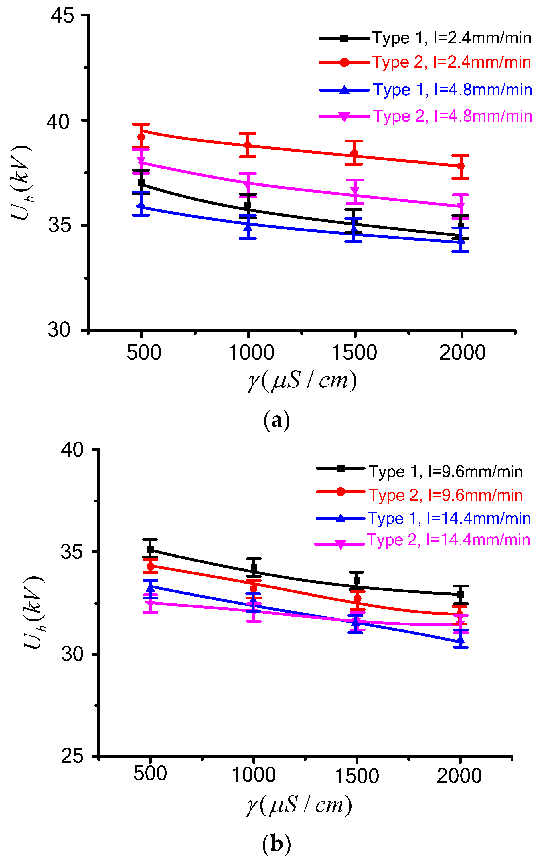
Figure 4.
Effects of rain intensity on flashover voltage: (a) I = 500, 1000 μS/min (b) I = 1500, 2000 μS/min.
Figure 4.
Effects of rain intensity on flashover voltage: (a) I = 500, 1000 μS/min (b) I = 1500, 2000 μS/min.

Figure 5.
Rain flashover process of the test specimens: (a) type 1; (b) type 2.

Figure 6.
Electric field distribution under rain conditions: (a) Simulation model; (b) type 1; (c) type 2.
Figure 6.
Electric field distribution under rain conditions: (a) Simulation model; (b) type 1; (c) type 2.
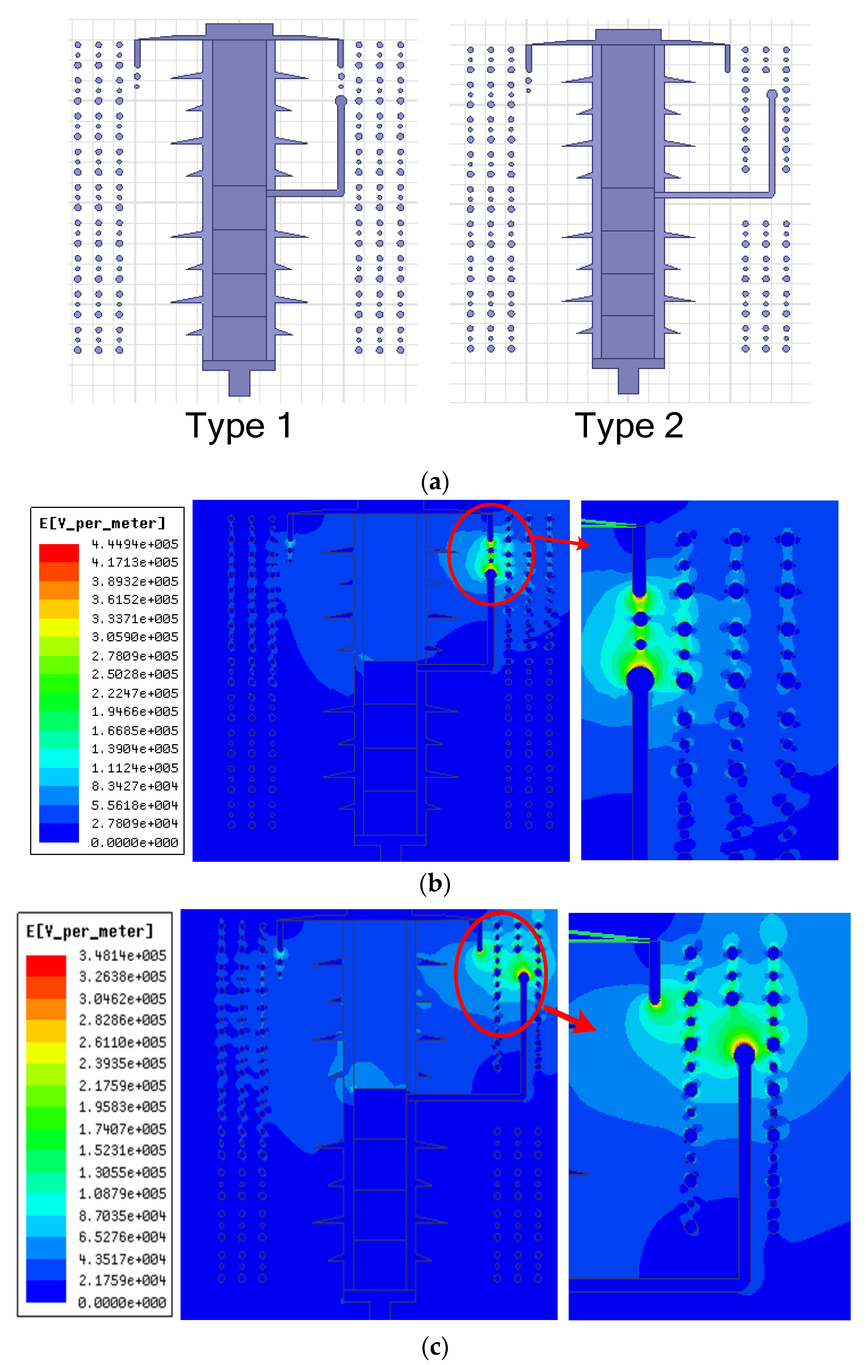
Figure 7.
Equivalent circuit model of the test specimens under rain condition.

Figure 8.
Wind effects on the flashover voltage.

Figure 9.
Wind effects on the flashover paths: (a) type 1; (b) type 2.
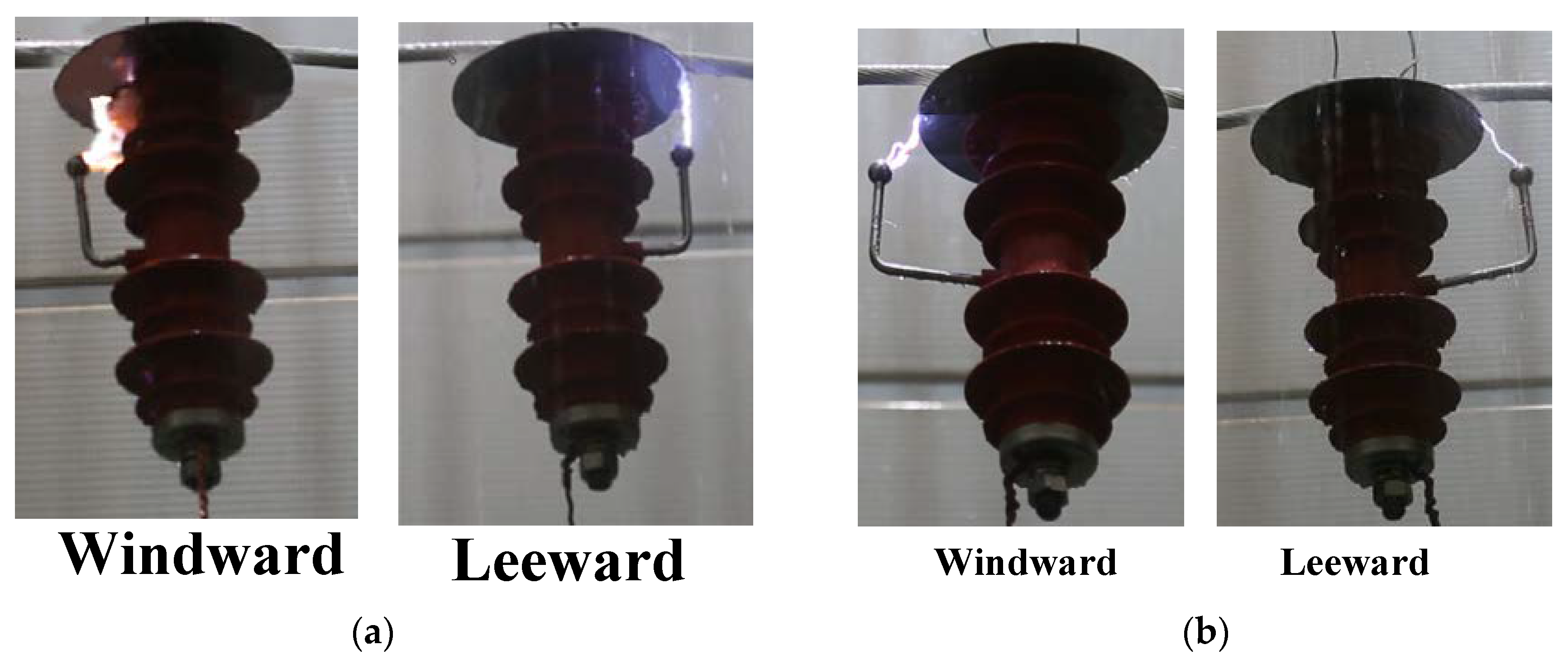
Figure 10.
Schematic diagram of water stream on the test specimens: (a) type 1; (b) type 2.

© 2018 by the authors. Licensee MDPI, Basel, Switzerland. This article is an open access article distributed under the terms and conditions of the Creative Commons Attribution (CC BY) license (http://creativecommons.org/licenses/by/4.0/).
Share and Cite
MDPI and ACS Style
Lu, J.; Xie, P.; Hu, J.; Jiang, Z.; Fang, Z. AC Flashover Performance of 10 kV Rod-Plane Air-Gapped Arresters under Rain Conditions. Energies 2018, 11, 1563. https://doi.org/10.3390/en11061563
AMA Style
Lu J, Xie P, Hu J, Jiang Z, Fang Z. AC Flashover Performance of 10 kV Rod-Plane Air-Gapped Arresters under Rain Conditions. Energies. 2018; 11(6):1563. https://doi.org/10.3390/en11061563
Chicago/Turabian StyleLu, Jiazheng, Pengkang Xie, Jianping Hu, Zhenglong Jiang, and Zhen Fang. 2018. "AC Flashover Performance of 10 kV Rod-Plane Air-Gapped Arresters under Rain Conditions" Energies 11, no. 6: 1563. https://doi.org/10.3390/en11061563
Note that from the first issue of 2016, this journal uses article numbers instead of page numbers. See further details here.