Research on Unbalance Fault-Tolerant Control Strategy of Modular Multilevel Photovoltaic Grid-Connected Inverter


1
College of Mechanical and Electrical Engineering, Northeast Forestry University, Harbin 150040, China
2
Maintenance Branch Company, State Grid Chongqing Electric Power Company, Chongqing 400039, China
3
School of Electrical Engineering and Automation, Harbin Institute of Technology, Harbin 150001, China
*
Author to whom correspondence should be addressed.
Energies 2018, 11(6), 1368; https://doi.org/10.3390/en11061368
Submission received: 4 April 2018
/
Revised: 3 May 2018
/
Accepted: 23 May 2018
/
Published: 28 May 2018
Abstract
:The average switching model of modular multilevel converter (MMC) is built in this paper when the hot reserved strategy is adopted as a fault-tolerant control. When the MMC SM faults, the rest of the SMs cannot support the DC-link voltage, which results in interruption of the inverter. To tackle this issue, a novel fault-tolerant control strategy is proposed to bypass the SM under fault and re-regulate the SM capacitor voltage and carrier phase-shift angle to maintain the main components of circulating current, and reduce the Total Harmonic Distortion (THD) of grid connected current to enable the stable operation of the photovoltaic inverter. The maximum power tracking control is improved to solve the problem of long restoration time when faults occur, based on a constant voltage startup method combined with a fix-step incremental conductance method. Simulations in MATLAB/Simulink and experimental results have verified the feasibility and effectiveness of the proposed control strategy.
1. Introduction
MMC (modular multilevel converter) can increase power and boost voltage by connecting several modules in series [1,2,3,4]. With its unique advantages of decentralized energy storages, modular structure, easy redundant SMs (SMs), simple fault identification, and clearance [5], MMC has been widely applied at various levels of power converters, such as high-voltage direct current (HVDC) transmission systems [6,7], DC–DC power electronic transformers [8], battery electric vehicles [9], distributed energy resources (DERs) [10,11], and flexible AC transmission systems (FACTS) [12]. Considering the long-existing issues of low utilization rate of light energy and potential influence on power grid in photovoltaic (PV) grid-connected system, the application of MMC in PV grid-connected systems is gaining more and more attention [13,14,15].
Lots of research has been conducted to find effective control methods for MMC topology [5,6,7,16,17]. Reference [5] proposes a control method based on a dynamic model, where six independent dynamical state variables are considered for effectively attaining the switching state functions of MMCs, as well as for an accurate control of the circulating currents. On basis of this, a multi-loop control strategy based on a six-order dynamic model of the modular multilevel converter is presented [6], and the MMC is well controlled during normal operation. Besides, novel modulation function-based control strategies are proposed in [7,16], and the complexity of the control system is lowered to a large extent, compared with traditional control methods. Reference [17] further proposed a novel control strategy for MMC based on differential flatness theory, to guarantee the stable operation of the MMC against the input disturbance, model errors, and system uncertainties.
However, the operation of MMC SMs in each bridge leg cannot be ensured. Once faults occur, the operation of MMC is influenced due to unbalance of SMs [18,19]. In order to keep MMC operating, redundant SMs would be added to each of the bridge legs, as cold [20] or hot [21] reserved. Thus, a proper fault-tolerant control strategy has been one of the hot research focus areas, to increase the utilization ration of converters.
In order to increase the utilization of redundant SMs, and avoid the problem of long capacitor charging time caused by putting redundant modules into operation as cold reserved, study of MMC fault-tolerant control strategy focuses more on hot reserved redundant SMs, at present. A rotating sliding choice box adopted in a novel fault tolerant control strategy is proposed [22] to select the operating SMs, and guarantees the operation with a nearly seamless transition and very short recovery time. Meanwhile, the line cycle is set as the rotating period in the control method, without increasing much switching loss. In [23], the faulty SM is located by the fault localization method, during which time period, the output voltage and current of the MMC are maintained smoothly, with no obvious distortion or overcurrent problems. Another fault-tolerant approach was proposed in [24] through suppressing the fundamental circulating current component caused by the asymmetrical operation. To deal with the unsymmetrical issue, a simple control strategy was proposed in [25] to adjust the capacitor voltage in the faulty arm, which enables the energy balanced in two complementary arms, and thus, the fault ride-through.
In [26], M redundant SMs exist as hot reserved, and are selected to be switched on in sequence. Meanwhile, a complicated start-up process for the redundant reserved SMs may be required, such as long charging time, which might lead to transient problems. In normal working status, the number of turn-on SMs of each bridge leg are the same as the converters without redundant SMs, which is N [27], and indicates that during normal operation, the number of the turn-on SMs in bridge legs is N + M. Once a SM fault happens, zero-sequence voltage is injected to make sure there is line voltage symmetry. However, the fault-tolerant method adopted here changes the converter output voltage, and is usually applied in the electric motor, due to the limitation of control strategy. In [28], when SM faults occur, the control strategy that SMs of the upper and lower bridge arms are removed symmetrically is adopted to maintain the main components of circulating current.
Aiming at the MMC fault-tolerant control strategy literature, [29,30] proposed a scheme that fault SMs coordinate with cold reserved SMs and realize the stable operation of converter and ensure the symmetry of bridge legs. However, this is not suitable for practical application.
Literature [31,32] proposed a control strategy based on zero-order voltage injection. Under the condition of constant line voltage, the system phase voltage is reconstructed to enhance the fault-through capability. However, the transient influence of the fluctuation of SM capacitor voltage and harmonics is injected after the fault happens.
In view of the points aforementioned, this work provides the following contributions:
- The average switching model of MMC with asymmetric fault is established. Proposed an improved fault-tolerant control strategy by bypassing fault SMs and dividing the converter work status into normal operation status and asymmetric fault-tolerant operation status.
- The focus of MMC on fault-tolerant control in two applications of photovoltaic grid-connected and HVDC transmission is different. This paper is mainly used to reduce total harmonic distortion rate of the grid-connected current; MMC can continue stable operation.
- The constant voltage tracking method of maximum power point tracking (MPPT) cannot complete accurate tracking when the photovoltaic inverter fault, in this case, the improved MPPT control method, is proposed combined with the incremental conductance algorithm; it can realize stable and accurate fault tolerance of MPPT control, and the problem of the voltage support and fault voltage recovery of the DC side bus are solved.
2. MMC Average Switch Model under Fault-Tolerance
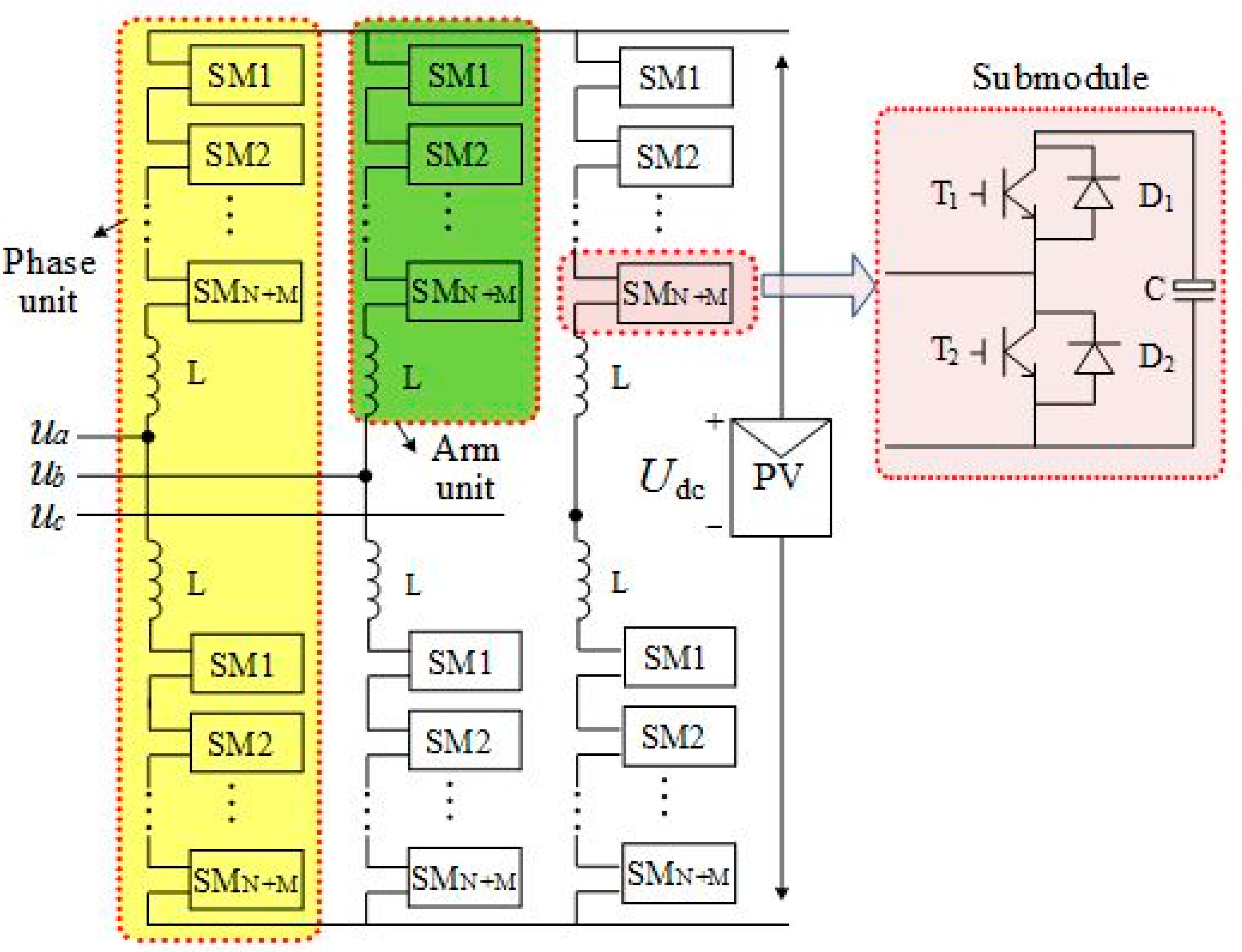
The double star chopper cells (DSCC) are used for the combination of power circuits using non-coupled buffer inductors with chopper cells. A modular multilevel converter (MMC) has been proposed in [33,34,35], intended for high-power applications, due to its simplicity of modulation and strong extensibility. The main topology is shown as Figure 1. The reason for naming is that the DSCC is based on two sets of star-configured converters, in which the low-voltage sides of multiple bidirectional chopper cells are cascaded to constitute each arm [36]. However, due to the existence of a large number of SMs, once a SM breaks down, it would have a severe impact on the whole PV system. Thus, fault-tolerant measurement must be employed to ensure normal operation of the system.
Firstly, characteristics of MMC are studied. The larger the number of SMs that grow, the more complex the switch function model becomes. Therefore, average switch model is introduced [37], which simplifies the model and makes it convenient for theoretical analysis of MMC.
Set phase A as an example, and analyze the characteristics of MMC under fault-tolerant condition. There are N SMs in every bridge leg and M redundant SMs. When SMs of the upper leg of phase A break down, the rest of the SMs are unable to support DC bus voltage, and the converter cannot operate normally. Thus, the capacitance voltage of the remaining SM in the upper bridge arm is.
where Mer is the number of fault SMs, U1 is the voltage of the rest SMs of fault bridge leg. Define N1 = M + N − Mer = Udc/U1, U0 is the capacitor voltage of lower bridge leg SMs under fault condition, N0 is the largest number of turn-on SMs in the lower bridge leg, which is N0 = Udc/U0. m and k are voltage and current modulation ratio, respectively. Assume modulation signal is averagely distributed, the upper and lower bridge leg SM average switch function Scp_a, Scn_a can be derived as
In order to perform analysis, Scp_a and Scn_a can be written as
where
In the literature [25], the AC side and DC side model of MMC have been introduced in detail, and are not covered in this article. The current of upper and lower bridge legs [38] is shown as Equation (6).
where I2f is the amplitude of double frequency component in circulating current.
The current of SM capacitor is derived as Equation (7) by using switch function.
Combining Equations (4)–(7), the current of SMs can be written as Equations (8) and (9).
Based on input and output power balance, we can obtain
For ease of analysis, it is assumed that the voltage and current modulation ratio are respectively written as
where Um and Im is the amplitude of the output voltage and current of phase A, combining Equations (8)–(10), mkcosφ = 2 is derived. Then substitute mkcosφ = 2 with Equations (8) and (9), (13) can be derived by eliminating the DC component.
where icp(n)_a(ωt) is the fundamental frequency component of the SM capacitor current of phase A upper and lower bridge legs, icp(n)_a(2ωt) is the double frequency component, and icp(n)_a(3ωt) is the triple frequency component.
When the AC components of current flow through the capacitor, the SM capacitor voltage will fluctuate.
where ucp_a(t), ucn_a(t) are, respectively, the voltage variation of phase A upper and lower bridge leg SMs.
The variation of upper and lower bridge legs SM output voltage Δucp_a(t), Δucn_a(t) can be written as Equations (16) and (17).
where Δu0, Δu(ωt), Δu(2ωt), Δu(3ωt), Δu(4ωt) are, respectively, the DC component, fundamental frequency component, double frequency components, triple frequency, and quadrifrequency component.
The voltage fluctuation of SM causes the fluctuation of bridge leg voltage, whose value is the sum of M + N − Mer SM output voltage fluctuation, and the value of the voltage fluctuation of lower bridge leg is the sum of M + N SM output voltage fluctuation, shown as (18).
The overall phase voltage variation is defined as the sum of the variations of upper and lower bridge legs voltage.
From the equation above, when asymmetry of the upper and lower bridge legs occurs, harmonic voltage will be introduced in the phase voltage, but double frequency component is an exception. When the voltage is imposed on bridge leg inductance, it causes the appearance of fundamental frequency component in the circulating current.
The DC side current is the sum of three phase circulating current.
Since the fundamental frequency component of fault phase is different from that of the other two phases, a fundamental frequency component is introduced in the DC side of converter.
Measurements must be taken to suppress the fundamental frequency component of circulating current when an asymmetric fault happens. The fundamental frequency component should be 0 in order not to introduce harmonics.
The largest number of turn-on SMs can be written as Equation (22).
3. Improvement of the MPPT Control in Asymmetric Fault-Tolerance
Based on the mathematical model of fault-tolerant inverter in the above content, an improved fault-tolerant control strategy for a single bypass fault module is designed for modularized multilevel inverter with carrier–phase modulation. The operation of the inverter is divided into two modes: normal mode and asymmetric fault-tolerant mode.
Mode 1: In general, inverters operate in normal working mode; when the redundant SM is also involved in the normal work of the inverter, the output voltage quality is improved. At this time, the maximum number of SMs that can be used in the upper and lower bridge arms is (M + N), and the carrier phase angle of each SM is 2π/(M + N). The SM of the corresponding position of the upper and lower bridge triggers the pulse difference is 180°, the output level of inverter is (M + N + 1), and the capacitor voltage reference on each SM is Udc/(M + N).
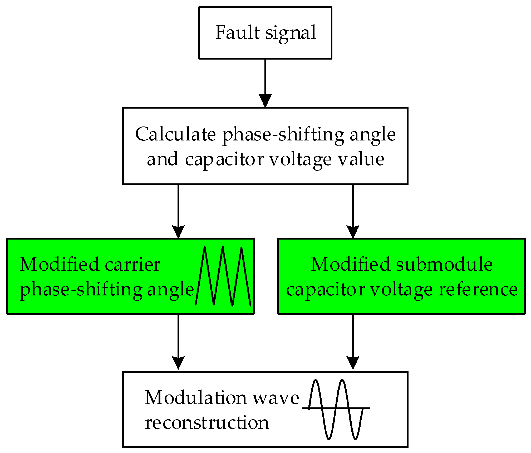
Mode 2: Under the asymmetric fault-tolerant mode, the degree of triangle carrier of the rest SMs in the upper bridge leg has a 2π/(M + N − Mer) difference with each other, but the carrier phase shifting degree of lower bridge leg SM remains unchanged. Figure 2 is the diagram of the unbalance fault-tolerant control. When there are Mer fault SMs, the fault SM should be bypassed, and then modify the carrier phase shifting degree of upper bridge leg and the value of SM capacitor voltage. The reference of SM capacitor voltage in the lower bridge leg should be changed to maintain the main components of circulating current by changing the modulation ratio, which maximizes the utilization of rest SMs.
Under the fault-tolerant condition, the capacitor voltage of non-fault phase bridge leg SMs is shown as Equation (23).
According to the analysis in the previous section, the value of total fluctuation of fault phase voltage can be derived as Equation (24).
From Equation (24), it can be seen that whether there is symmetric fault-tolerant control strategy or asymmetric control strategy, the fundamental frequency of fault phase voltage is maintained at 0, which ensures that there is no extra fundamental frequency component introduced in the circulating current. However, the DC component and double frequency component of fault phase voltage change after fault happens, and will cause a tiny unbalance of three phase power output. Yet, it is not considered here.
To sum up, compared with injecting zero-order voltage control strategy, the asymmetric control strategy is operated under the condition of constant phase voltage. Compared with the control strategy, which cuts off Mer SMs both in the upper and lower bridge legs to ensure the balance of bridge legs, the proposed strategy not only maintains the main component of circulating current, but also increases the number of turn-on SMs of fault phase and the level of output voltage, at the same time suppressing harmonics in MMC output current. However, due to the unbalance of upper and lower SM triangle carrier, high-order harmonics around the switching frequency of circulating current are enhanced, and can be filtered by increasing the value of bridge leg inductance.
When the inverter in the grid-connected system has a SM failure, the DC bus voltage of the common side will drop, due to the remaining SM capacitor voltage being not height enough to support. In order to solve the problem that the recovery time of the DC bus voltage is long due to the limitation of the output step of the MPPT algorithm, the constant voltage start method is applied to the MPPT in fault-tolerant control.
Constant voltage tracking method is based on the feature that when the illumination and temperature do not change, the voltage of the maximum power output point is approximately 0.8 times open circuit voltage of the PV array, so that the PV array could work at the maximum power point. This control method with simple principle and fast-tracking speed is an open-loop control of the maximum power point voltage, and cannot track accurately, especially when the external conditions change. Therefore, it is combined with the conductance increment method to achieve maximum power point tracking control in fault-tolerance. The specific tracking process is shown in Figure 3, continuously sampling the output voltage and output current of the PV array and detecting, in real time, whether a SM has failed. If the MMC is running normally, the maximum power point of the PV array continues to be tracked by the conductance increment method. If the SM fails, then the fault-tolerant control strategy is improved, and there is a change to the maximum power point tracking link to use constant voltage tracking at first, making Umppt approximately equal 0.8 times of the open circuit voltage Uoc. When the PV array output voltage is higher than 0.8Uoc, then the conductance incremental method is used at the maximum power point for accurate tracking control.
4. Simulation Research
In order to verify the feasibility of the asymmetric fault-tolerant control strategy proposed in this paper, a model is built in MATLAB/Simulink (R2016b, MathWorks company, USA) to simulate the single and two SMs in phase A, respectively. The system simulation parameters are shown in Table 1.
4.1. Simulation Results Analysis of a SM Fault in Phase A
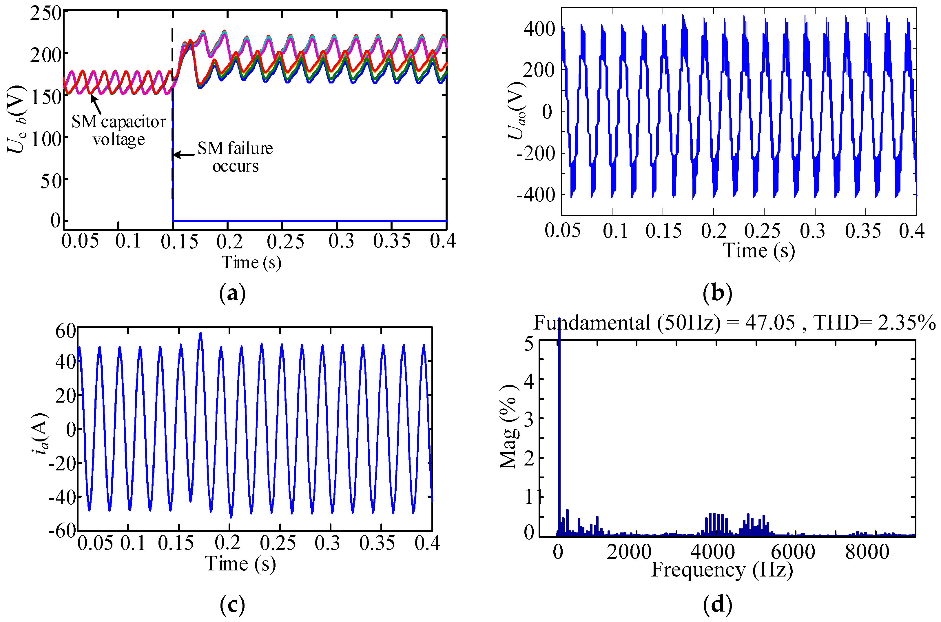
When the upper arm of phase A has a SM failure, the carrier phase shift angle is changed to 2π/4, and the reference voltage of the SM of the upper arm is set to 814/4 = 203.5 V. The carrier phase shift angle of the lower arm is maintained at 2π/5, and the reference voltage of each SM is changed to 182 V according to Equation (16). The carrier phase shift angle of the non-fault phases and the reference voltage of the SM do not change.
As shown in Figure 4a, the SM on the upper arm of phase A has a SM fault at 0.15 s, and is bypassed immediately. After the fault-tolerant measure is taken, after 0.05 s, the SM capacitor voltage tracks the reference voltage. The voltage of the SM in the upper arm is stabilized near 203.5 V, and that of the lower arm is stabilized at around 182 V. As shown in Figure 4b, the triangular carrier of the upper and lower arms is no longer symmetrical compared to the normal operation of the inverter after the fault tolerance is taken. Therefore, the amount of the output level increases.
The output current of the asymmetric fault-tolerant MMC, in this case, is shown in Figure 4c. It can be seen that the output current of inverter is almost the same as before after adopting improved fault-tolerance control. As shown in Figure 4d, the harmonic distortion of the output current of Phase A is 2.35% after fault-tolerant control, but the equivalent switching harmonics of 4000 Hz in output current increase.
4.2. Analysis of Simulation Results of Two SM Faults in Phase A
When the number of SMs in the single-phase arm is increased, the asymmetric fault-tolerant control strategy proposed in this paper is more beneficial to the control of the output current of the grid-connected inverter. When two SMs on the upper arm of phase A fault, the carrier phase shift angle of the bridge is changed to 2π/3, and the SM capacitance voltage reference value of the upper arm is set to 814/3 = 271 V, the carrier phase shift angle of the lower arm maintains 2π/5, each SM capacitor voltage reference value is changed to 210 V, according to Equation (22), as shown in Figure 5a. By contrast, in Figure 5b, when the symmetrical fault-tolerant control is adopted, the output voltage of inverter is only 4 levels, which is much less than the improved asymmetrical tolerance control in this paper. There are two SMs in the upper arm of phase A that malfunctioned at 0.15 s, and the SMs are removed immediately. The output voltage amplitude is approximately the same, as shown in Figure 5c,d. The carrier phase shift angle of the non-fault phase and the capacitance voltage reference value remain unchanged. As shown in Figure 5e–h, it can be seen that when the improved asymmetric fault-tolerant control is used, the current distortion rate is only 3.41%, which is lower than 5.04%, due to the increase of the output level of the inverter that is better than symmetrical fault-tolerant control.
From the simulation analysis, it is can be seen that, compared to the traditional symmetrical fault-tolerant control strategy, the asymmetric fault-tolerant control strategy proposed in this paper increases the output level of the inverter on the basis of that the main components in the circulation do not change, and reduce the harmonic distortion rate of the output current. However, the triangular carrier is asymmetric when the upper and lower arms are modulated, which increases the equivalent switching harmonics in the bridge arm circulation.
4.3. Simulation Analysis of the MPPT Control Link in Fault-Tolerance
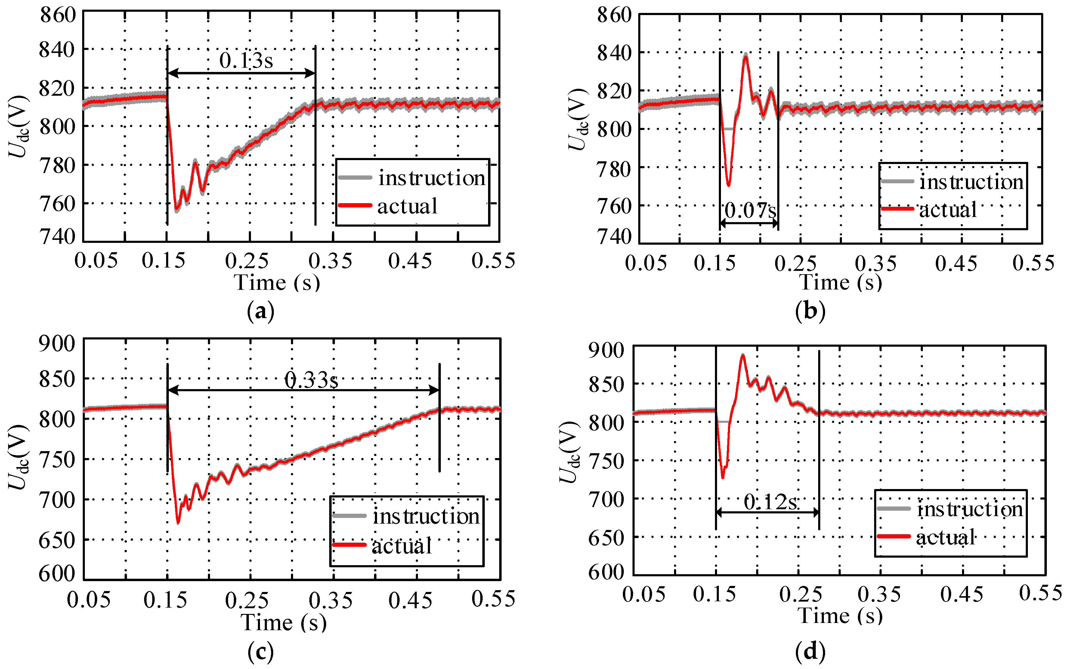
In the system, the inverter is connected to the PV array, and the MPPT control is simulated. Respectively simulate the situation on the arm of A phase, which has a single and two SM failure. When only the conductance increment method is used for tracking, the command voltage Umppt is obtained by superimposing a small disturbance voltage on the basis of the current bus voltage. As shown in Figure 6a, a SM on the upper arm of phase A is bypassed at 0.15 s. When the common DC bus voltage drops, it costs 0.17 s to restore the original voltage level due to the limit of the disturbance voltage to the command voltage. When the constant voltage method before conductance incremental method is used to track the point, at a single module fault moment, as shown in Figure 6b, set the command voltage as a constant value of 800 V. The bus voltage is quickly returned to the maximum power point voltage. Then, accurately track the maximum power point by the conductance incremental method and the initial voltage value can be restored in just 0.07 s.
When the upper arm of phase A has two SMs that are bypassed, the DC bus voltage instantaneously drops, more seriously. As shown in Figure 6c, only by the conductance incremental method to track the point, the system failure needs 0.33 s to restore to the original level. When the constant voltage method before conductance incremental method is used, only 0.12 s are needed to recover the initial voltage, which is shown in Figure 6d.
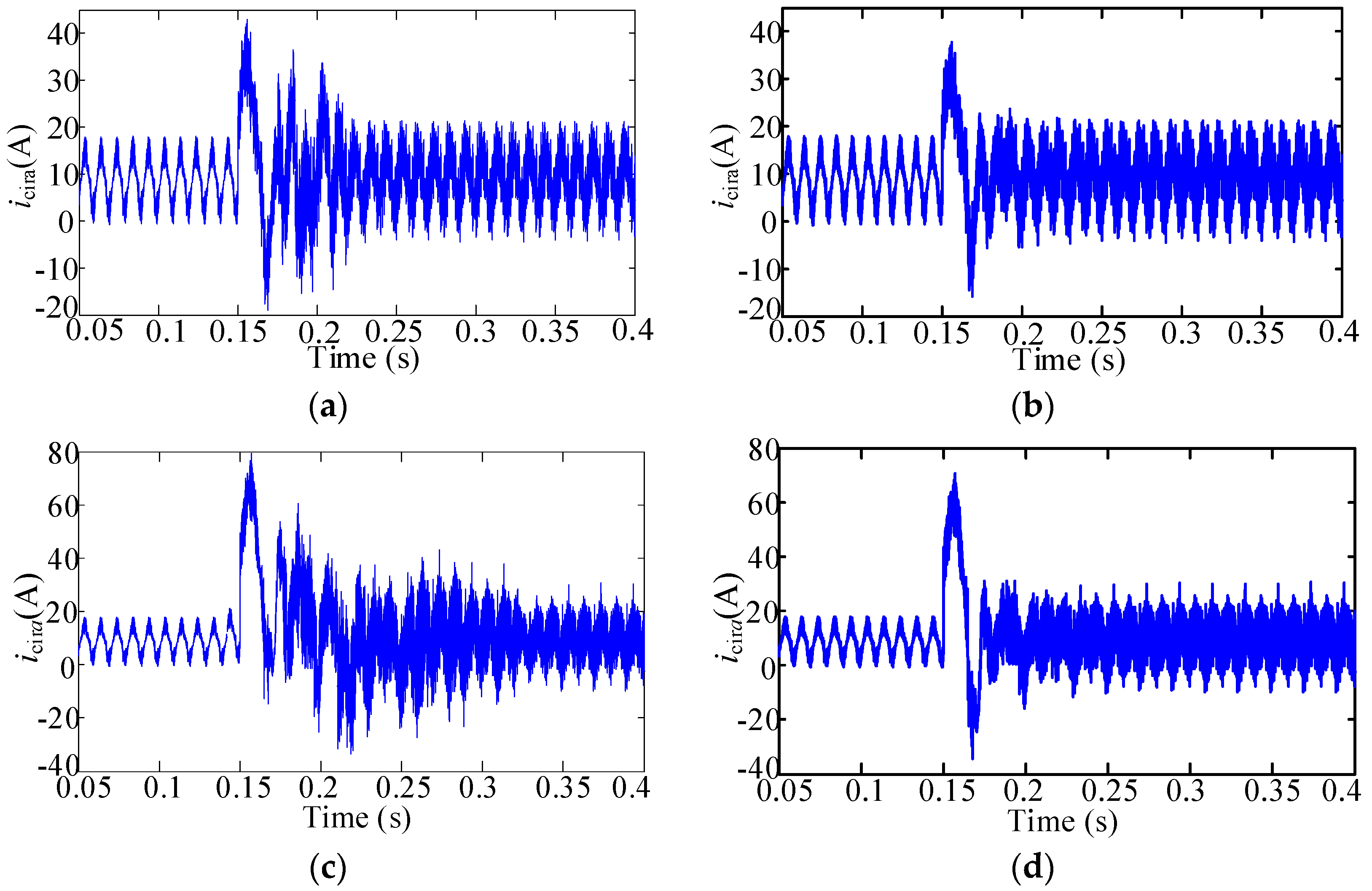
Figure 7 further shows variation of the circulating current of MPPT control under fault tolerant condition. Figure 7a,b are the circulating currents of conventional and improved MMPT control when only one SM is bypassed in the upper arm, while Figure 7a,c show the circulating currents of conventional and improved MMPT control when two SMs are bypassed in the upper arm.
As is shown in Figure 6 and Figure 7, the restoration time of bus voltages and circulating currents under improved MMPT control algorithm, in Figure 3, has been shortened to a large extent. The waveforms prove the effectiveness of the proposed MPPT control under fault-tolerant operation.
Through the simulation analysis of the maximum power tracking algorithm in the case of two kinds of fault bypass cases, it can be seen that the MPPT algorithm, which is tracked by the constant voltage method before conductance incremental method, can realize a quick track to the maximum power point Um when the SM fails, shortening the time that the system is affected by the failure.
From Figure 8a,b, the harmonic distortion rate of the output current of the inverter is 2.39%, after adopting the asymmetric fault-tolerant control strategy when there is a SM fault on the upper arm of phase A. The main component of the circulation does not change, and the fundamental frequency component is 0.4 A, while the second harmonic component is 4.86 A. From Figure 8c,d, the harmonic distortion rate of the output current of the inverter is 3.53% when the fault-tolerant control strategy is adopted when there are two failed SMs on the upper arm of phase A. The main components in the circulation did not change, and the fundamental frequency component is 0.8 A, while the second harmonic component is 4.4 A.
5. Experimental Verification
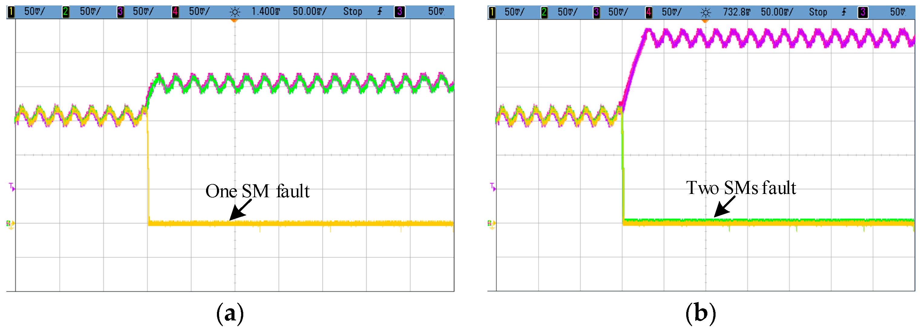
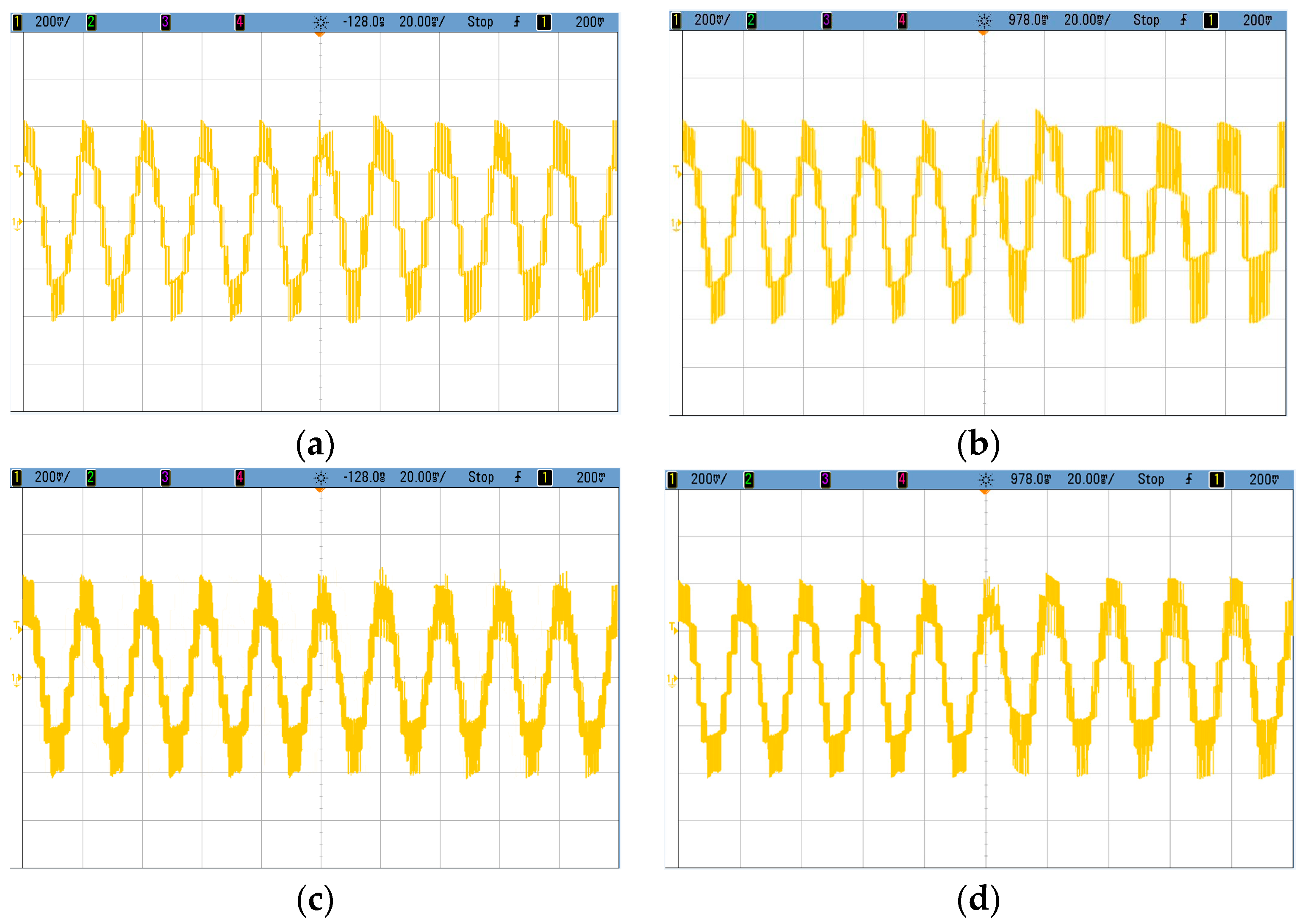
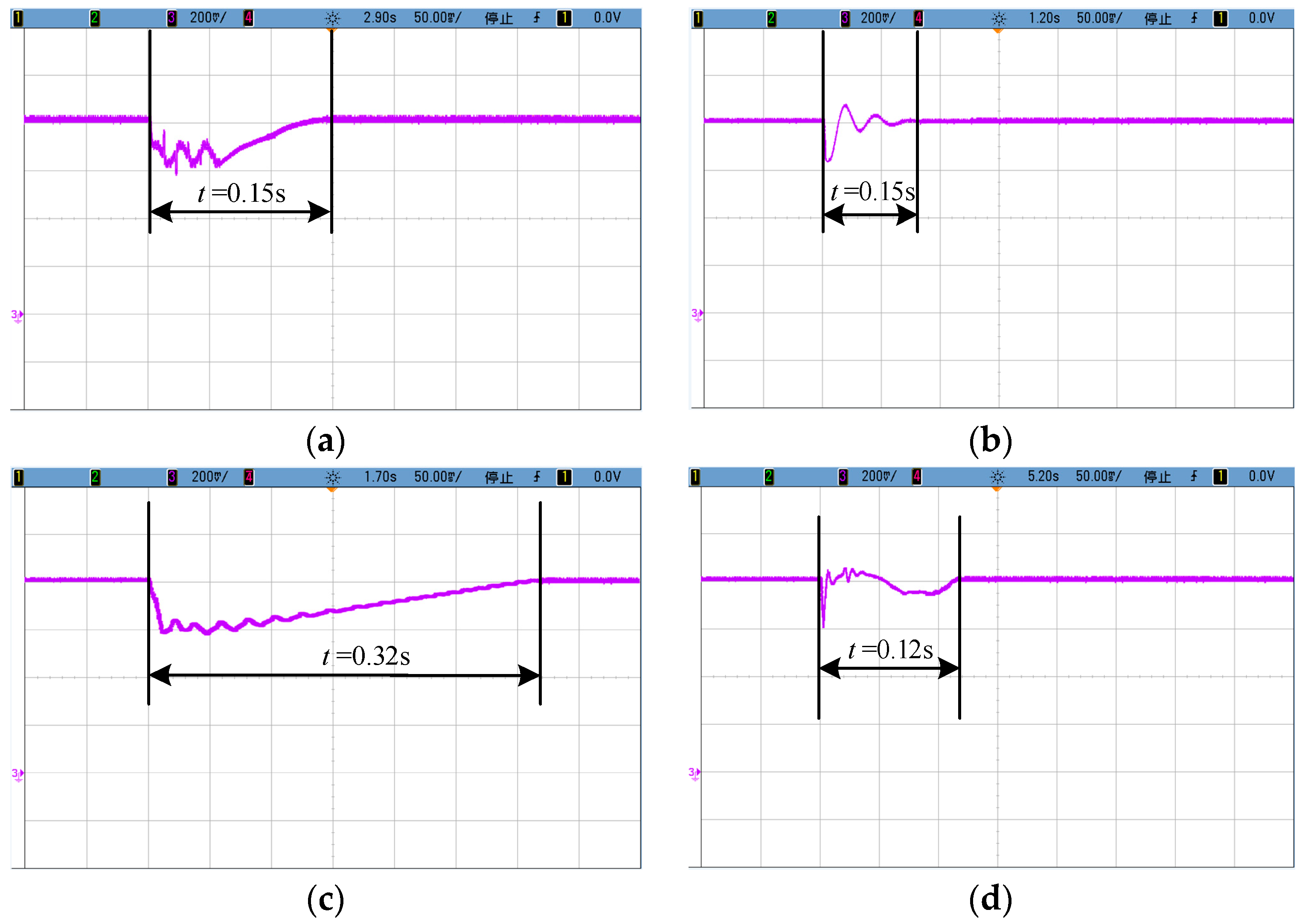
An experimental prototype MMC with ten SMs in each phase is implemented. The parameters of this platform are given in Table 1. The upper arm SM capacitor voltage operation waveforms of MMC with one SM and two SM faults are demonstrated in Figure 9. The experimental results show that the more failures of SMs, the higher the voltage the remaining modules will assume. When the SM fault occurs on the upper or lower arm of MMC, the output voltage level is different, with symmetrical and asymmetrical fault-tolerant control strategy in Figure 10. It can be seen from Figure 10a,b that when a fault occurs at one or two SMs, the level of the output voltage of MMC is N − Mer + 1 after adopting symmetric fault-tolerance control. However, when the asymmetric fault-tolerant control is used, the output voltage level of MMC is increased, which can reduce the output voltage harmonics, just as shown in Figure 10c,d. With the same fault scenario, the fault-tolerant operation waveforms of MMC with the conventional and improved MPPT control under Mer = 1 or 2 are shown in Figure 11. In a SM failure cases, DC-link voltage drop is instantaneous, which is affected by the SM fault. It can be seen from the comparison in Figure 11a–d, the improved MPPT algorithm can shorten the DC-link voltage recovery time.
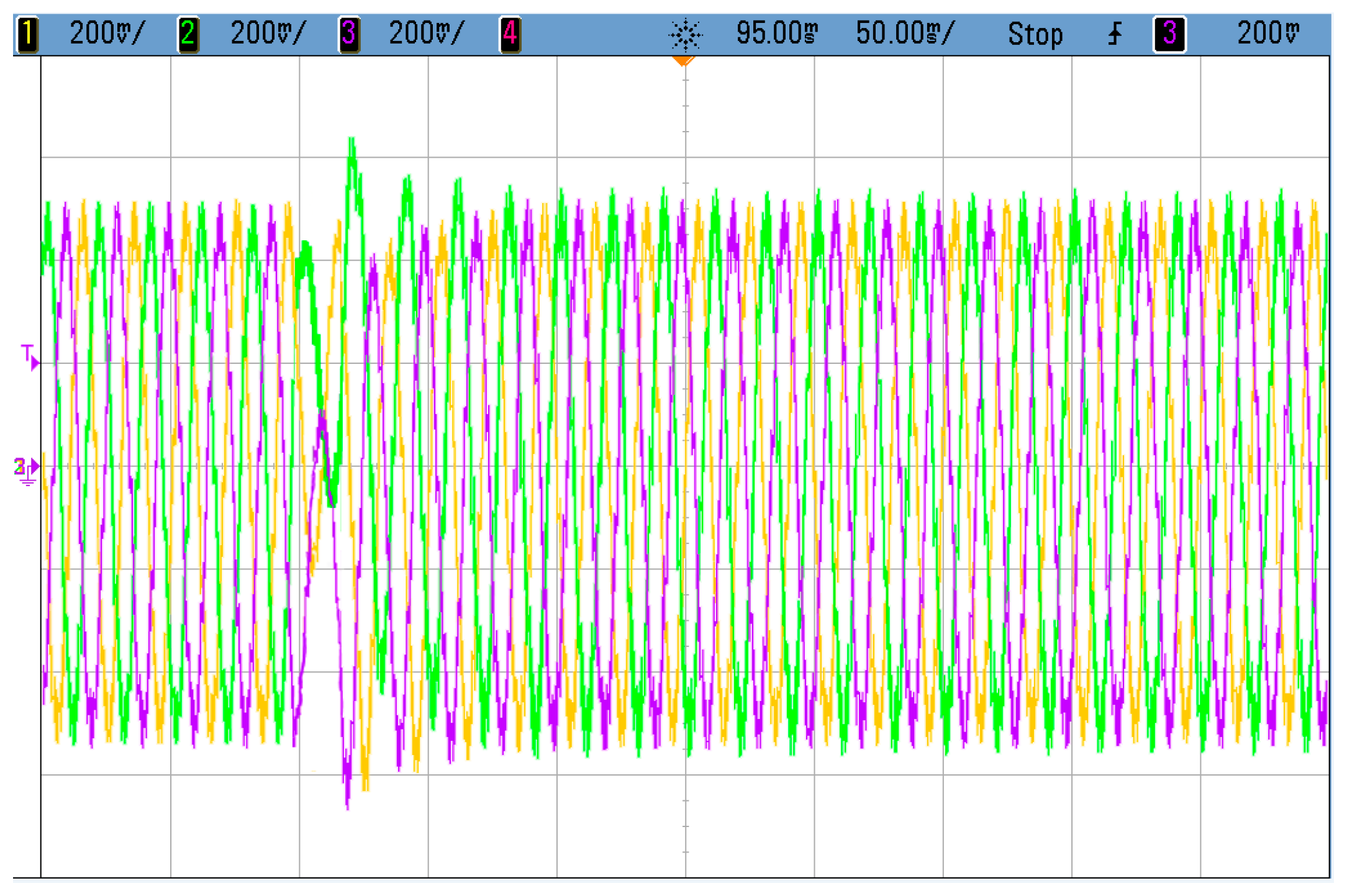
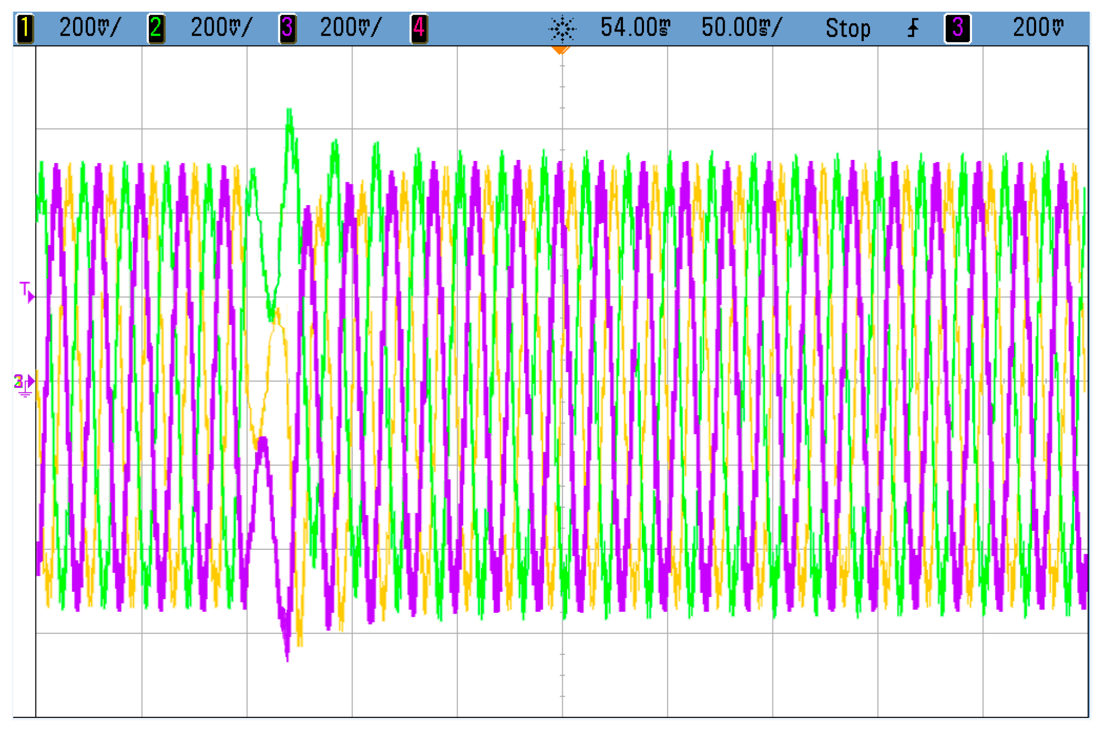
From Figure 12 and Figure 13, it can be concluded that with the proposed fault-tolerant control strategy, MMC can realize the fault ride-through even when there are one or two SMs under fault, and the dynamic transition of MMC output current during the fault-recovery stage is short and smooth, with only a very small fluctuation. The experimental results verify the effectiveness of the proposed method.
6. Conclusions
An improved asymmetric fault-tolerant control strategy of photovoltaic grid connected MMC with hot reserve redundancy is studied. By changing capacitor voltage of SMs and phase shift angle of carrier wave, it is ensured that the main ingredient in the circulating current is changed. Meanwhile, the total harmonic distortion of the photovoltaic inverter grid-current in the post-fault period is reduced. Combining the advantages of constant voltage start and fixed-step conductance increment, accurate tracking, and control of the maximum power point tracking are realized, and the recovery time of the voltage fluctuation caused by the fault of the DC bus voltage is shortened. The MATLAB/Simulink simulation results show that the harmonic distortion of the output current is lower, and the level of MMC output voltage is increased when adopting the asymmetric fault-tolerant control method, compared with conventional method. The reference voltage of the SM capacitor on the non-faulty arm of the fault phase is lower. Therefore, it is proven that the fault-tolerant control strategy is feasible. Simulation and experimental results have verified the feasibility and effectiveness of the proposed fault tolerant control strategy.
Author Contributions
All authors contributed to this work by collaboration. Y.L. was the main author of this manuscript. D.L. and Y.J. performed the experiments, Q.W. and W.S. provided some useful suggestions in the construction of the paper. All authors revised and approved the publication.
Acknowledgments
This research was funded by the Project Supported by the Fundamental Research Funds for the Central Universities (No. 2572017BB13), Harbin Municipal Science and Technology Bureau Innovative Talent Foundation (No. 2017RAQXJ044) and China Postdoctoral Science Foundation funded project (No. 2018M631893).
Conflicts of Interest
The authors declare no conflict of interest.
References
- Moranchel, M.; Bueno, E.; Sanz, I.; Rodríguez, F.J. New Approaches to Circulating Current Controllers for Modular Multilevel Converters. Energies 2017, 10, 86. [Google Scholar] [CrossRef]
- Li, X.; Song, Q.; Liu, W.; Xu, S.; Zhu, Z.; Li, X. Performance Analysis and Optimization of Circulating Current Control for Modular Multilevel Converter. IEEE Trans. Ind. Electron. 2016, 63, 716–727. [Google Scholar] [CrossRef]
- Xu, J.; Zhao, P.; Zhao, C. Reliability Analysis and Redundancy Configuration of MMC with Hybrid SM Topologies. IEEE Trans. Power Electron. 2016, 31, 2720–2729. [Google Scholar] [CrossRef]
- Zhang, F.; Li, W.; Joós, G. A Voltage-Level-Based Model Predictive Control of Modular Multilevel Converter. IEEE Trans. Ind. Electron. 2016, 63, 5301–5312. [Google Scholar] [CrossRef]
- Mehrasa, M.; Pouresmaeil, E.; Zabihi, S.; Catalão, J.P. Dynamic model, control and stability analysis of mmc in HVDC transmission systems. IEEE Trans. Power Deliv. 2017, 32, 1471–1482. [Google Scholar] [CrossRef]
- Mehrasa, M.; Pouresmaeil, E.; Zabihi, S.; Vechiu, I.; Catalão, J.P. A multi-loop control technique for the stable operation of modular multilevel converters in HVDC transmission systems. Int. J. Electr. Power Energy Syst. 2018, 96, 194–207. [Google Scholar] [CrossRef]
- Mehrasa, M.; Pouresmaeil, E.; Zabihi, S.; Trujillo Caballero, J.C.; Catalão, J.P. A novel modulation function-based control of modular multilevel converters for high voltage direct current transmission systems. Energies 2016, 9, 867. [Google Scholar] [CrossRef]
- Gowaid, I.; Adam, G.; Ahmed, S.; Holliday, D.; Williams, B. Analysis and Design of a Modular Multilevel Converter with Trapezoidal Modulation for Medium and High Voltage dc-dc Transformers. IEEE Trans. Power Electron. 2015, 30, 5439–5457. [Google Scholar] [CrossRef]
- Quraan, M.; Yeo, T.; Tricoli, P. Modular Multilevel Converters for HVDC Applications: Review on Converter Cells and Functionalities. IEEE Trans. Power Electron. 2015. [Google Scholar] [CrossRef]
- Soong, T.; Lehn, P.W. Internal Power Flow of a Modular Multilevel Converter with Distributed Energy Resources. IEEE J. Emerg. Sel. Top. Power Electron. 2014, 2, 1127–1138. [Google Scholar] [CrossRef]
- Pouresmaeil, E.; Mehrasa, M.; Shokridehaki, M.A.; Rodrigues, E.M.G.; Catalão, J.P.S. Control of Modular Multilevel Converters for Integration of Distributed Generation Sources into the Power Grid. In Proceedings of the 2015 IEEE International Conference on Smart Energy Grid Engineering (SEGE), Oshawa, ON, Canada, 17–19 August 2015; pp. 1–6. [Google Scholar]
- Du, S.; Liu, J. A Study on DC Voltage Control for Chopper-Cell-Based Modular Multilevel Converters in D-STATCOM Application. IEEE Trans. Power Deliv. 2013, 28, 2030–2038. [Google Scholar] [CrossRef]
- Fei, R.; Gong, X.; Huang, S. A novel grid-connected PV system based on MMC to get the maximum power under partial shading conditions. IEEE Trans. Power Electron. 2017, 32, 4320–4333. [Google Scholar]
- Bayat, H.; Yazdani, A. A Power Mismatch Elimination Strategy for an MMC-Based Photovoltaic System. IEEE Trans. Energy Convers. 2018. [Google Scholar] [CrossRef]
- Rojas, C.A.; Kouro, S.; Perez, M.A.; Echeverria, J. DC-DC MMC for HVDC Grid Interface of Utility-Scale Photovoltaic Conversion Systems. IEEE Trans. Ind. Electron. 2018, 65, 352–362. [Google Scholar] [CrossRef]
- Mehrasa, M.; Pouresmaeil, E.; Akorede, M.F.; Zabihi, S.; Catalão, J.P. Function-based modulation control for modular multilevel converters under varying loading and parameters conditions. IET Gener. Transm. Distrib. 2017, 11, 3222–3230. [Google Scholar] [CrossRef]
- Mehrasa, M.; Pouresmaeil, E.; Taheri, S.; Vechiu, I.; Catalão, J.P. Novel Control Strategy for Modular Multilevel Converters Based on Differential Flatness Theory. IEEE J. Emerg. Sel. Top. Power Electron. 2017, 6, 888–897. [Google Scholar] [CrossRef]
- Li, S.; Wang, X.; Yao, Z.; Li, T.; Peng, Z. Circulating Current Suppressing Strategy for MMC-HVDC Based on Non-ideal Proportional Resonant Controllers Under Unbalanced Grid Conditions. IEEE Trans. Power Electron. 2015, 30, 387–397. [Google Scholar] [CrossRef]
- Moon, J.W.; Kim, C.S.; Park, J.W.; Kang, D.W.; Kim, J.M. Circulating Current Control in MMC Under the Unbalanced Voltage. IEEE Trans. Power Deliv. 2013, 28, 1952–1959. [Google Scholar] [CrossRef]
- Li, W.; Li, G.; Zeng, R.; Ni, K.; Hu, Y.; Wen, H. The Fault Detection, Localization, and Tolerant Operation of Modular Multilevel Converters with an Insulated Gate Bipolar Transistor (IGBT) Open Circuit Fault. Energies 2018, 11, 837. [Google Scholar] [CrossRef]
- Li, B.; Zhang, Y.; Yang, R.; Xu, R.; Xu, D.; Wang, W. Seamless transition control for modular multilevel converters when inserting a cold-reserve redundant SM. IEEE Trans. Power Electron. 2015, 30, 4052–4057. [Google Scholar] [CrossRef]
- Li, K.; Yuan, L.; Zhao, Z.; Lu, S.; Zhang, Y. Fault-Tolerant Control of MMC with Hot Reserved SMs Based on Carrier Phase Shift Modulation. IEEE Trans. Power Electron. 2017, 32, 6778–6791. [Google Scholar] [CrossRef]
- Li, B.; Shi, S.; Wang, B.; Wang, G.; Wang, W.; Xu, D. Fault Diagnosis and Tolerant Control of Single IGBT Open-Circuit Failure in Modular Multilevel Converters. IEEE Trans. Power Electron. 2016, 31, 3165–3176. [Google Scholar] [CrossRef]
- Deng, F.; Tian, Y.; Zhu, R.; Chen, Z. Fault-tolerant approach for modular multilevel converters under SM faults. IEEE Trans. Ind. Electron. 2016, 63, 7253–7263. [Google Scholar] [CrossRef]
- Hu, P.; Jiang, D.; Zhou, Y.; Liang, Y.; Guo, J.; Lin, Z. Energy-balancing Control Strategy for Modular Multilevel Converters Under SM Fault Conditions. IEEE Trans. Power Electron. 2014, 29, 5021–5030. [Google Scholar] [CrossRef]
- Son, G.T.; Lee, H.J.; Nam, T.S.; Chung, Y.H.; Lee, U.H.; Baek, S.T.; Hur, K.; Park, J.W. Design and control of a modular multilevel HVDC converter with redundant power modules for noninterruptible energy transfer. IEEE Trans. Power Deliv. 2012, 27, 1611–1619. [Google Scholar]
- Liu, H.; Loh, P.C.; Blaabjerg, F. Review of fault diagnosis and faulttolerant control for modular multilevel converter of HVDC. In Proceedings of the 39th Annual Conference of the IEEE Industrial Electronics Society (IECON 2013), Vienna, Austria, 10–13 November 2013; pp. 1242–1247. [Google Scholar]
- Choi, J.; Han, B.; Kim, H. New scheme of phase-shifted carrier pwm for modular multilevel converter with redundancy SMs. IEEE Trans. Power Deliv. 2016, 31, 407–409. [Google Scholar] [CrossRef]
- Li, K.; Zhao, Z.; Yuan, L.; Lu, S.; Pan, B.; Lu, Z. Fault tolerant control of MMC with redundant sub-modules based on carrier phase shift modulation. In Proceedings of the 2016 IEEE Applied Power Electronics Conference and Exposition (APEC), Long Beach, CA, USA, 20–24 March 2016; pp. 2613–2619. [Google Scholar]
- Song, W.; Huang, A. Fault-tolerant design and control strategy for cascaded H-bridge multilevel converter-based STATCOM. IEEE Trans. Ind. Electron. 2010, 57, 2700–2708. [Google Scholar] [CrossRef]
- Deng, F.; Chen, Z.; Khan, M.R.; Zhu, R. Fault Detection and Localization Method for Modular Multilevel Converters. IEEE Trans. Power Electron. 2015, 30, 2721–2732. [Google Scholar] [CrossRef]
- Choi, J.; Han, B. An improved phase-shifted carrier PWM for modular multilevel converters with redundancy sub-modules. J. Power Electron. 2016, 16, 473–479. [Google Scholar] [CrossRef]
- Liu, Y.; Chen, Q.; Li, N.; Xie, B.; Wang, J.; Ji, Y. On DC-side Impedance Frequency Characteristics Analysis and DC Voltage Ripple Prediction under Unbalance Conditions for MMC-HVDC System Based on Maximum Modulation Index. J. Power Electron. 2016, 16, 319–328. [Google Scholar] [CrossRef]
- Hagiwara, M.; Akagi, H. PWM control and experiment of modular multilevel converters. In Proceedings of the 2008 IEEE Power Electronics Specialists Conference, Rhodes, Greece, 15–19 June 2008; pp. 154–161. [Google Scholar]
- Hagiwara, M.; Akagi, H. Control and Experiment of Pulse width-Modulated Modular Multilevel Converters. IEEE Trans. Power Electron. 2009, 24, 1737–1746. [Google Scholar] [CrossRef]
- Akagi, H. Classification, terminology, and application of the modular multilevel cascade converter (MMCC). IEEE Trans. Power Electron. 2011, 26, 3119–3130. [Google Scholar] [CrossRef]
- Song, Q.; Liu, W.; Li, X.; Rao, H.; Xu, S.; Li, L. A Steady-State Analysis Method for a Modular Multilevel Converter. IEEE Trans. Power Electron. 2013, 28, 3702–3713. [Google Scholar] [CrossRef]
- Wu, W.; Wu, X.; Yin, J.; Jing, L.; Wang, S.; Li, J. Characteristic Analysis and Fault-Tolerant Control of Circulating Current for Modular Multilevel Converters under Sub-Module Faults. Energies 2017, 10, 1827. [Google Scholar] [CrossRef]
Figure 1.
The schematic of the modular multilevel converter.

Figure 2.
The diagram of the unbalance fault-tolerant control.

Figure 3.
Constant voltage startup fix-step incremental conductance method.
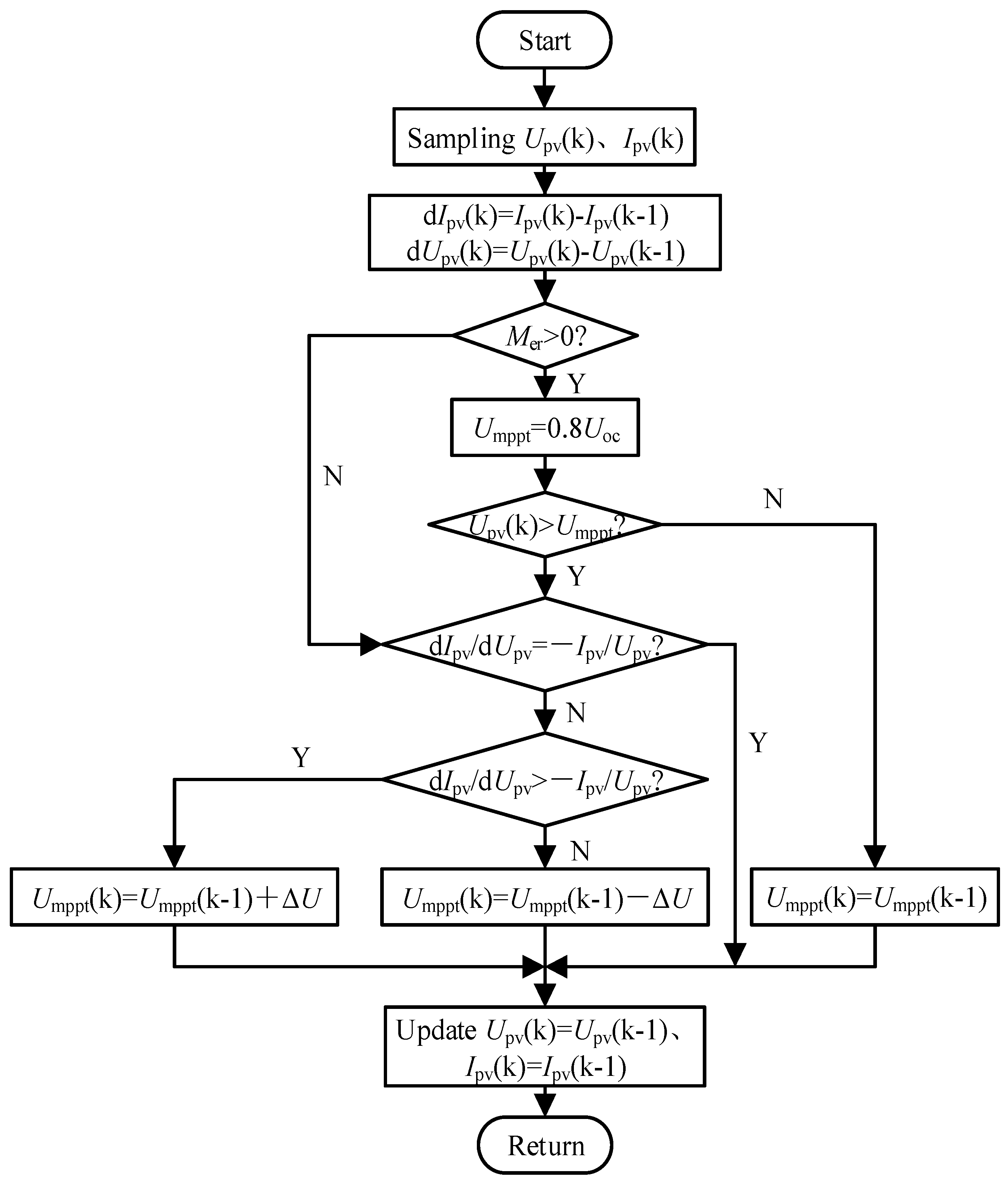
Figure 4.
Unbalance fault-tolerant control under one SM fault in phase A upper arm. (a) Asymmetrical fault-tolerant phase A SM capacitor voltage waveform; (b) Asymmetrical fault-tolerant modular multilevel converter (MMC) output voltage waveform; (c) Asymmetric fault-tolerant MMC output current waveform; (d) Asymmetrical fault-tolerant output current harmonic analysis after 0.25 s.

Figure 5.
Unbalance fault-tolerant control under two SM faults in phase A upper arm. (a) Asymmetrical fault-tolerant phase A module capacitor voltage waveform; (b) Symmetrical fault-tolerant phase A module capacitor voltage waveform; (e) Asymmetrical fault-tolerant MMC output current; (f) Symmetrical fault-tolerant MMC output current; (g) Asymmetrical fault-tolerant MMC output current harmonic analysis after 0.25 s; (h) Symmetrical fault-tolerant MMC output current harmonic analysis after 0.25 s.
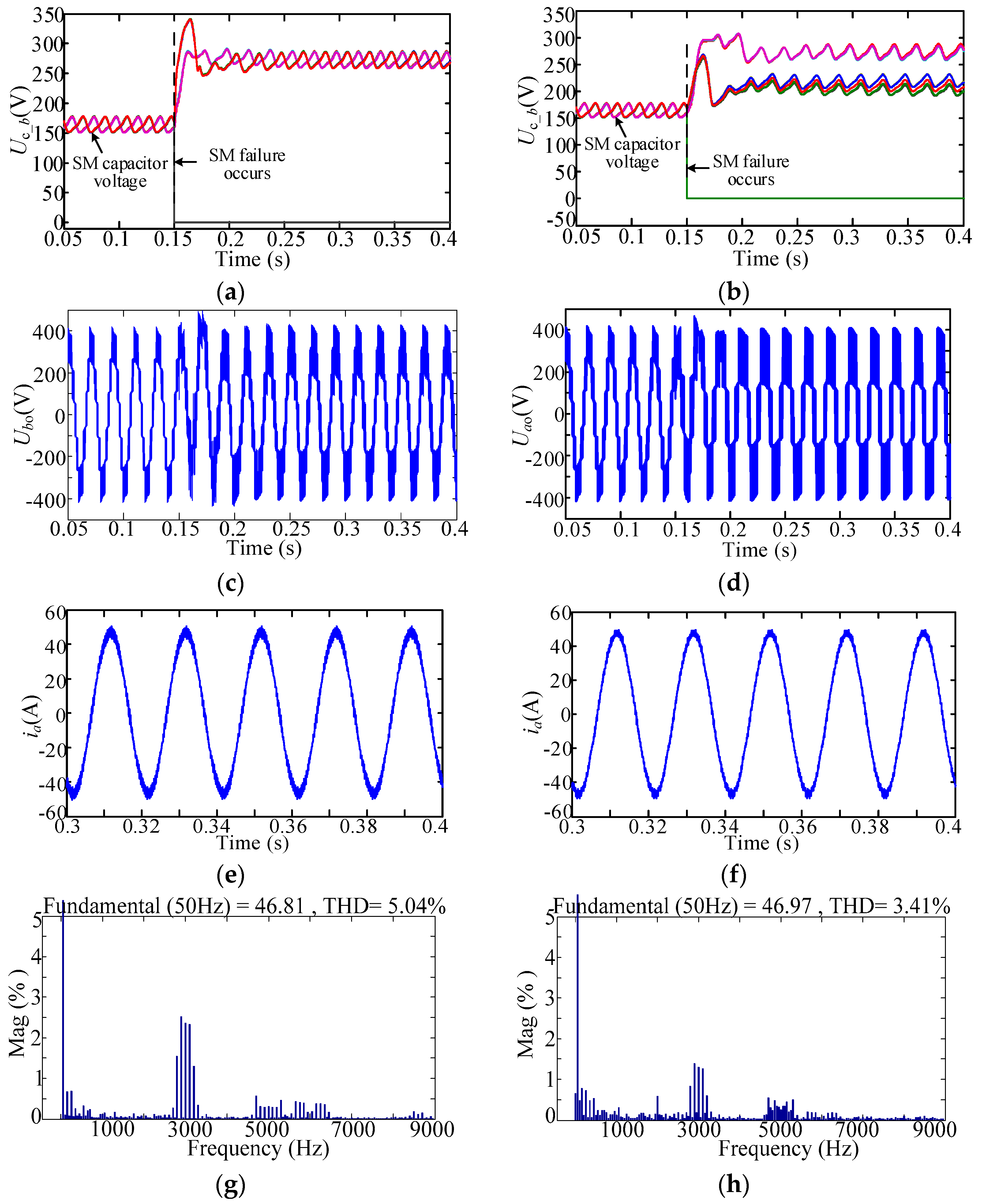
Figure 6.
Bus voltage of MPPT control under fault-tolerant condition. (a) Mer = 1, conventional MPPT bus voltage; (b) Mer = 1, Improved MPPT bus voltage; (c) Mer = 2, conventional MPPT bus voltage; (d) Mer = 2, improved MPPT bus voltage.
Figure 6.
Bus voltage of MPPT control under fault-tolerant condition. (a) Mer = 1, conventional MPPT bus voltage; (b) Mer = 1, Improved MPPT bus voltage; (c) Mer = 2, conventional MPPT bus voltage; (d) Mer = 2, improved MPPT bus voltage.

Figure 7.
Circulating currents of MPPT control under fault-tolerant condition. (a) Mer = 1, conventional MPPT circulating current; (b) Mer = 1, improved MPPT circulating current; (c) Mer = 2, conventional MPPT circulating current; (d) Mer = 2, improved MPPT circulating current.
Figure 7.
Circulating currents of MPPT control under fault-tolerant condition. (a) Mer = 1, conventional MPPT circulating current; (b) Mer = 1, improved MPPT circulating current; (c) Mer = 2, conventional MPPT circulating current; (d) Mer = 2, improved MPPT circulating current.

Figure 8.
Unbalance fault-tolerant control of one stage PV grid. (a) Mer = 1, MMC grid connection current; (b) Mer = 1, MMC internal circulation; (c) Mer = 2, MMC grid connection current; (d) Mer = 2, MMC internal circulation.
Figure 8.
Unbalance fault-tolerant control of one stage PV grid. (a) Mer = 1, MMC grid connection current; (b) Mer = 1, MMC internal circulation; (c) Mer = 2, MMC grid connection current; (d) Mer = 2, MMC internal circulation.
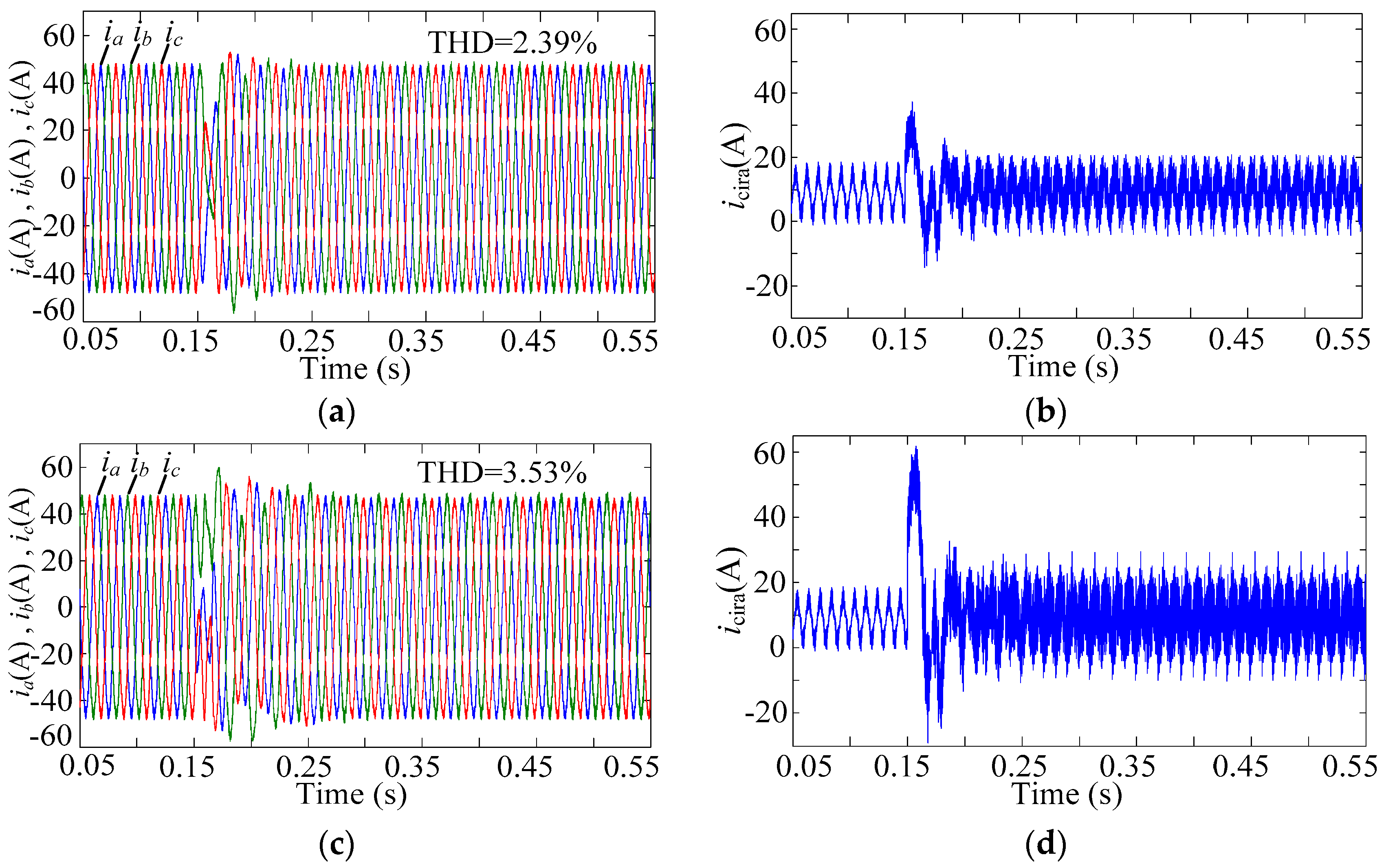
Figure 9.
Experimental results of upper arm SM capacitor voltages. (a) Mer = 1; (b) Mer = 2.

Figure 10.
Experimental results of MMC output voltage. (a) Symmetrical fault-tolerant control under Mer = 1; (b) Symmetrical fault-tolerant control under Mer = 2; (c) Asymmetrical fault-tolerant control under Mer = 1; (d) Asymmetrical fault-tolerant control under Mer = 2.
Figure 10.
Experimental results of MMC output voltage. (a) Symmetrical fault-tolerant control under Mer = 1; (b) Symmetrical fault-tolerant control under Mer = 2; (c) Asymmetrical fault-tolerant control under Mer = 1; (d) Asymmetrical fault-tolerant control under Mer = 2.

Figure 11.
Experimental results of MMC DC-link voltage. (a) Conventional MPPT control under Mer = 1; (b) Improved MPPT control under Mer = 1; (c) Conventional MPPT control under Mer = 2; (d) Improved MPPT control under Mer = 2.
Figure 11.
Experimental results of MMC DC-link voltage. (a) Conventional MPPT control under Mer = 1; (b) Improved MPPT control under Mer = 1; (c) Conventional MPPT control under Mer = 2; (d) Improved MPPT control under Mer = 2.

Figure 12.
Experimental results of MMC output current under Mer = 1.

Figure 13.
Experimental results of MMC output current under Mer = 2.


Table 1.
The parameters of simulation system.
| Parameters | Value | Parameters | Value |
|---|---|---|---|
| DC bus voltage | 800 V | Amount of SM (M + N) | 5 |
| Inductance of arm | 1.5 mH | Current loop Kp | 10 |
| Capacitance of SM | 2200 μF | Current loop Kr | 16 |
| Grid-side filtering inductance | 3 mH | Current loop ωc | 5 |
| Switching frequency | 1 kHz | Voltage loop factor | 1 |
| Rated power | 7 KW | ||
| Grid voltage | 311 V | - | - |
| Grid frequency | 50 Hz | - | - |
© 2018 by the authors. Licensee MDPI, Basel, Switzerland. This article is an open access article distributed under the terms and conditions of the Creative Commons Attribution (CC BY) license (http://creativecommons.org/licenses/by/4.0/).
Share and Cite
MDPI and ACS Style
Liu, Y.; Li, D.; Jin, Y.; Wang, Q.; Song, W. Research on Unbalance Fault-Tolerant Control Strategy of Modular Multilevel Photovoltaic Grid-Connected Inverter. Energies 2018, 11, 1368. https://doi.org/10.3390/en11061368
AMA Style
Liu Y, Li D, Jin Y, Wang Q, Song W. Research on Unbalance Fault-Tolerant Control Strategy of Modular Multilevel Photovoltaic Grid-Connected Inverter. Energies. 2018; 11(6):1368. https://doi.org/10.3390/en11061368
Chicago/Turabian StyleLiu, Yiqi, Danhua Li, Yu Jin, Qingbo Wang, and Wenlong Song. 2018. "Research on Unbalance Fault-Tolerant Control Strategy of Modular Multilevel Photovoltaic Grid-Connected Inverter" Energies 11, no. 6: 1368. https://doi.org/10.3390/en11061368
Note that from the first issue of 2016, this journal uses article numbers instead of page numbers. See further details here.