Active-Reactive Additional Damping Control of a Doubly-Fed Induction Generator Based on Active Disturbance Rejection Control


1
Department of Electrical Engineering, North China Electric Power University, Baoding 071003, China
2
Inner Mongolia Power Economic Research Institute, Huhehaote 010000, China
*
Author to whom correspondence should be addressed.
Energies 2018, 11(5), 1314; https://doi.org/10.3390/en11051314
Submission received: 21 March 2018
/
Revised: 21 April 2018
/
Accepted: 17 May 2018
/
Published: 21 May 2018
Abstract
:Large-scale wind power interfacing to the power grid has an impact on the stability of the power system. However, with an additional damping controller of the wind generator, new ways for improving system damping and suppressing the low frequency oscillation (LFO) of power systems can be put forward. In this paper, an active-reactive power additional damping controller based on active disturbance rejection control (ADRC) is proposed. In order to improve the precision of the controller, the theory of data driven control is adopted, using the numerical algorithms for subspace state space system identification (N4SID) to obtain the two order model of the ADRC controlled object. Based on the identification model, the ADRC additional damping controller is designed. Taking a 2-area 4-machine system containing the doubly fed induction generator (DFIG) wind farm as an example, it is verified that the active-reactive additional damping controller designed in this paper performs well in suppressing negative-damping LFO and forced power oscillation. When the operation state of the power system changes, it can still restrain the LFO effectively, showing stronger robustness and better effectiveness compared to the traditional proportional–integral–derivative (PID) additional damping controller.
1. Introduction
Low frequency oscillations (LFO) in power systems commonly occur in long-distance, heavily-loaded transmission lines or weak connection lines of interconnected systems, and are especially prone to appear when fast-response excitation systems are put into operation. If they fail to damp the LFO at the very beginning, the power oscillations may even diverge, leading to subsequent problems such as the overcurrent tripping into the connection lines or even being out of sync and splitting between the systems, which seriously threatens the stability of power system [1,2].
With the growing shortage of resources and environmental pollution problems, the development of new energy becomes inevitable in the electric power industry [3,4,5]. Among the renewable resources, wind power is one of the most potential types of energy for its wide distribution and easy conversion to electricity. References [4,5,6] introduce the development of the global wind power industry. It can be concluded that after more than ten years’ development, wind power has become one of the most mature renewable energy sources. However, for the volatility and randomness of wind power and the high penetration of wind power to the power grid, it brings more challenges to the LFO of the power system. At the same time, many researches show that wind generators can affect system damping by influencing the power flow or the coupling between generators and power systems, which provides a new way to suppress the LFO [7,8,9,10]. Therefore, it is of great practical significance to put forward a new method to solve the LFO in a power system with large-scale wind power.
At present, many scholars have carried out research on the control algorithms for damping the LFO with variable speed wind turbines [11,12,13,14,15,16]. In reference [17], a novel input-output linearization algorithm-based inter-area oscillation damping control strategy for the doubly fed induction generator (DFIG) was proposed. The simulation results show that the proposed damping controller can damp the power swing more quickly compared to the conventional power system stabilizer (PSS). Reference [18] proposes a hybrid modulated active damping scheme to mitigate the potential power oscillations. Reference [19] investigates the inter-area low-frequency damping control strategies of a DFIG-based wind farm through oscillation transient energy function (OTEF) analysis. PSSs installed in DFIG were used in reference [20,21] to provide additional damping to electromechanical modes. An active-damping strategy is proposed in reference [22,23] and based on small-signal analysis; a low-bandwidth design for the power or generator torque controller of permanent magnet synchronous generator (PMSG) can help to reduce the oscillation amplitude. Reference [24] proposed a second-order sliding mode-based damping controller of DFIG for interarea oscillations and simulation results show the improvement on system performance in interarea oscillation damping and demonstrate the robustness of the proposed control scheme in a wide operation region.
The operational state of a power system is changing all the time, and therefore, the effectiveness of the controllers designed for a certain operational state may worsen when the state changes to another one. As a solution, the auto disturbance rejection control (ADRC) technology has been introduced for its simple structure, easy implementation, and strong robustness in engineering modeling [25,26].
Reference [27] proposed an ADRC of an induction motor based on an ant colony optimization (ACO) algorithm, in order to realize the precise decoupling of the induction motor and the disturbance compensation. To achieve the high dynamic performance of the drive system, an improved ADRC was proposed to realize decoupling control and disturbance rejection in [28]. Reference [29] presented a novel robust control scheme employing three first-order ADRCs. As a result, the implementation of the proposed scheme on a digital signal processor (DSP) is easier, and the runtime of the proposed ADRC control algorithm is shorter. In [30], an ADRC strategy-based sensorless control scheme for an interior permanent magnet synchronous motor (IPMSM) drive is proposed and the experimental results confirmed that the expected dynamic performance could be achieved.
ADRC technology enjoys plenty of merits but also has restrictions. If the disturbance to the system is too large, the burden of the extended state observer (ESO) will become heavier and the accuracy of the ADRC will decrease. Moreover, it is difficult to apply ADRC to the controllers when the controlled object is complex modeled in high order or in strong coupling.
In this paper, the subspace model identification method is proposed to design the ADRC controller. Firstly, the theory of a data-driven control is introduced. Taking DFIG as the research object, the I/O data of the controlled object is adopted and the mathematical model of the controlled objects is obtained by N4SID as a known part of the ADRC. It can effectively reduce the burden of the state observer and improve the precision of ADRC. Finally, an additional damping controller based on improved ADRC technology is designed. A model based on 2-area 4-machine system with DFIG wind farm is built in DIgSILENT to verify the effectiveness of the proposed method.
The remainder of this paper is structured as follows. In Section 2, the components and error analysis of ADRC are designed. An active-reactive power additional damping controller of DFIG based on ADRC is established in Section 3. In Section 4, the robustness and effectiveness of the proposed controller are verified by the example of 2-area 4-machine system and compared with the results of traditional a proportional–integral–derivative (PID) additional damping controller. Finally, conclusions are drawn in Section 5.
2. The Principle of ADRC
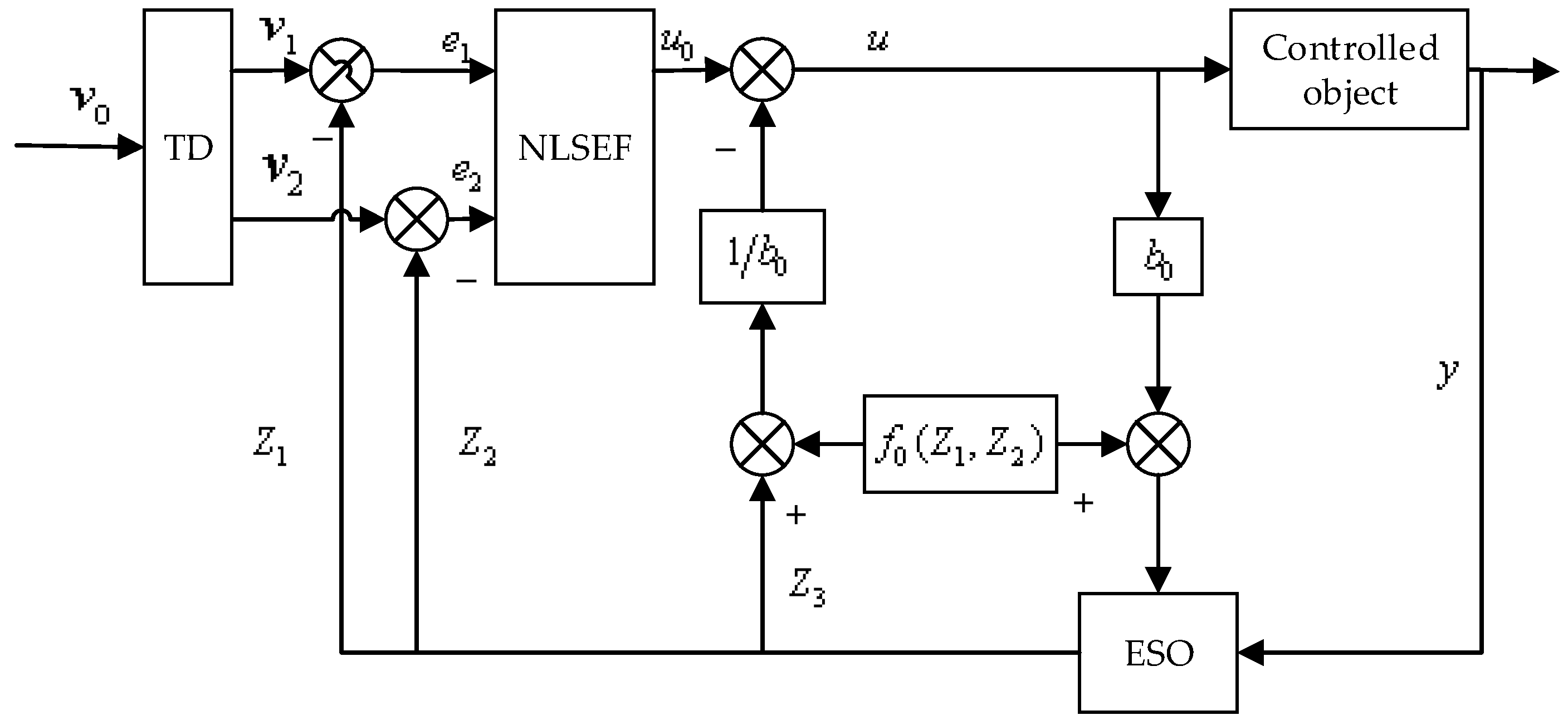
ADRC is a mathematical model that does not depend on the controlled object. It provides uncertain factors, such as the total system disturbances and corresponding compensations. Even if the controlled object encounters uncertain disturbances or changes, it can achieve a good control effect [25,26,31]. It is a kind of control method with strong adaptability and robustness. As an example of the two order controlled object shown in Equation (1), the structure of ADRC is shown in Figure 1.
where and : the definite part and parameters of the controlled object; : the sum of unmodeled dynamics and disturbances, in which , .
2.1. The Composition of ADRC
The ADRC is mainly composed of four parts: the tracking differentiator (TD), the extended state observer (ESO), the state error feedback, and the disturbance estimation compensation. In order to reduce the high frequency tremor, this paper discretizes the ADRC with the disturbance tracking compensation capability and obtains its complete discrete algorithm. The concrete model is as follows:
- 1.
- Modeling of TD
Taking , a set value as the input, , a smooth input by tracking through TD, and , a differential signal. TD here is arranged for reducing the initial error and alleviate the contradiction between the rapidity and overshoot of transition process.
where velocity factor; filter factor; simulation step length; discrete time-optimal control synthesis function, its expression as follows:
- 2.
- Modeling of ESO
The estimation of state variables, and , are obtained by the output and input of the system, and , a new state variable expanded by the disturbance affecting the controlled output via ESO. Their expressions are listed as Equations (4) and (5).
where : model of the known part of the controlled system; : a set of parameters of observer; , , : tracking signal, and tracking , , respectively.
- 3.
- Modeling of the state error feedback
The appropriate feedback mechanism can suppress the disturbance effectively and improve the performance of the closed loop system greatly. The state error feedback mechanism shown in Equation (6) is adopted in this paper.
where and are the estimate errors and differential of errors between ranged transition process and system output.
In this paper, the nonlinear feedback is adopted, in which is a damping coefficient, is the gain of the control quantity, and is a fast factor.
- 4.
- Modeling of the disturbance estimation compensation
As shown in Equation (7), the linearization of the dynamic compensation is achieved by the disturbance quantity of the ESO estimation and the feedback of the state error, so that the closed-loop system has a satisfactory performance.
2.2. Error Analysis of ESO
According to the Equations (1) and (4), the error equation of the observer is obtained as follows:
where , ESO works at a nonlinear state for better transient dynamic performances. When the system reaches steady state, the equations in (9) comes to zero.
Through a large number of simulation experiments, taking , , , the steady-state error of the error equations are expressed as follows:
As long as is greater than , the estimation error comes to zero, but it is noted that over the general assembly leads to the estimated value oscillation, so the appropriate value of should be selected. The Laplace transformation of the steady state equation of the Equation (8) is made to obtain the transfer function between and as follows:
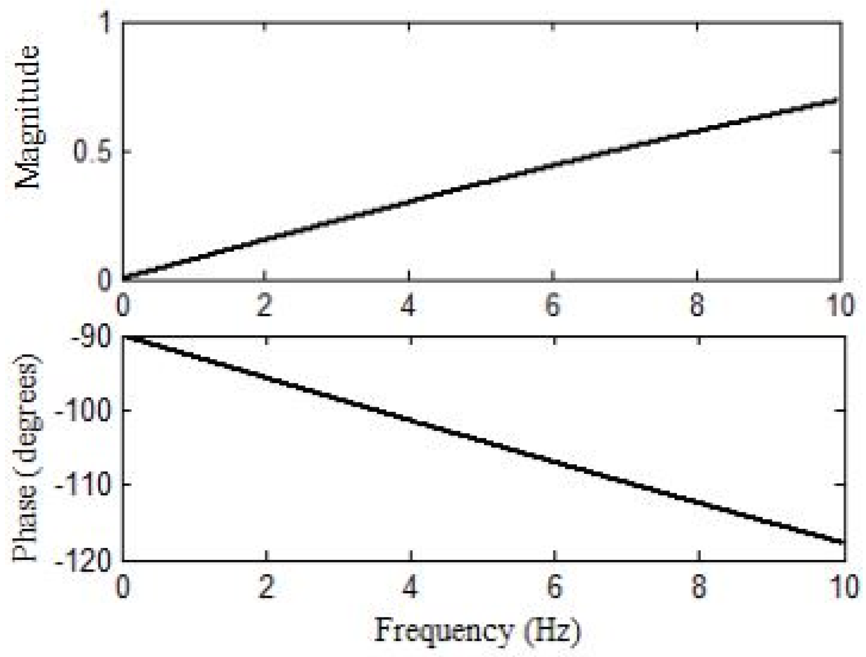
The concept of bandwidth is used to design observer parameters , and , which are configured as for two order controlled objects. Therefore, ESO parameters can be designed based on , , , where is the observer bandwidth. The larger becomes, the more accurate the observer will be. However, is more sensitive to the noise when it becomes a big value, making the observer much more vulnerable. For simplification, taking , when , , and , the amplitude frequency response of the disturbance observation error transfer function is shown in Figure 2.
In Figure 2, the disturbance observation error for low-frequency stage is smaller according to the calculated , and , and the observer performs well in suppressing the LFO. The three parameters of ESO should be adjusted to ensure the stability and achieve the best control effect.
3. Design of DFIG Additional Damping Controller Based on ADRC
Based on the DFIG converter model, this paper designs an active-reactive hybrid additional damping controller of DFIG. At the same time, in order to improve the control precision, the N4SID (numerical algorithm for subspace state space system identification) is proposed to identify the state space model of the controlled object.
3.1. Modeling of DFIG
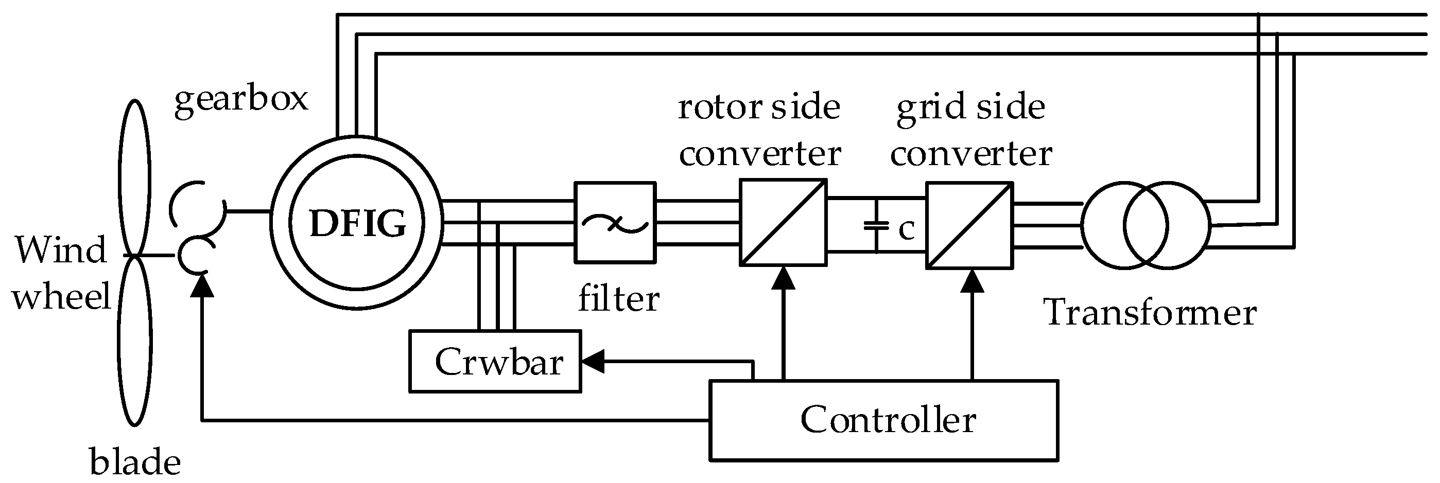
The basic diagram of DFIG is shown in Figure 3, including wind wheel, blade, gearbox, bearing, induction generator, and its control part (controller, rotor side converter, capacitance, grid side converter) and etc. [32]. The dynamic model is set up as follows.
- 1.
- Aerodynamics model
The kinetic energy of the airstream that flows through the wind wheel per unit time is wind power. Because the actual output power of the wind wheel depends on the efficiency of the interaction between the wind and the wind wheel in the energy conversion process, that is power coefficient , so the actual output mechanical power of the wind turbine can be expressed as follows:
where is wind speed, is the air density and is the turbine rotor-plane radius.
The power coefficient is an important parameter to characterize the efficiency of the wind turbine. Generally, a general high-order nonlinear function is used to describe its characteristics. In this paper, the following functions are used to calculate :
where ~ is the fitting parameters of the curve , is the blade pitch angle, is the tip speed ratio, which is the ratio of blade tip velocity to wind speed , is the rotating speed of the wind wheel.
- 2.
- Modeling of the mechanical transmission system
The DFIG transmission system mainly includes a low speed drive shaft, gearbox, and a high speed drive shaft. In the analysis of power system stability, two mass block models represent the shafting of wind turbines. The model equation is as follows:
where , : inertia time constant of the wind turbine and generator; : input mechanical torque of the wind turbine; : electromagnetic torque of the generator; : electromagnetic power transmitted by the rotor to the stator through the gap; : rotating speed of wind turbine; : rotor speed of the generator; : synchronous speed of the generator; : twisting angle of the drive shaft; : strength coefficient of the wind drive shaft; : damping coefficient.
- 3.
- Modeling of the DFIG
In order to mimic the interface connecting the DFIG electromechanical transient model and the power grid phasor model, the asynchronous machine uses the motor practice on the stator and rotor side, neglecting the stator transient process and the stator resistance. The mathematical model of the DFIG written in d-q synchronously rotating reference frame can be expressed as follows:
where : slip of doubly-fed machines; and : d-axis and q-axis components of the stator voltage and rotor voltage of DFIG; and : d-axis and q-axis components of the stator current and rotor current of DFIG; and : d-axis and q-axis components of the stator flux linkage and rotor flux linkage of DFIG; : stator and rotor inductor; : stator and rotor resistance; : mutual inductance of stator and rotor.
- 4.
- Modeling of the DFIG side converter
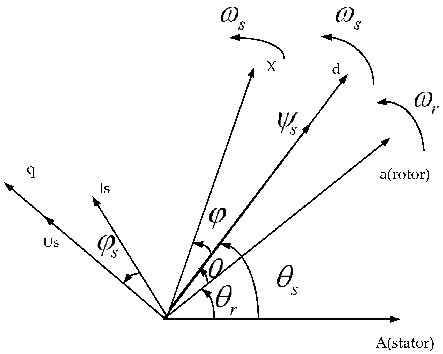
The stator side converter model adopts the stator flux oriented vector control mode. Due to the operation of Grid-connected DFIG, the stator current is always running at 50 Hz. Under this frequency, the stator resistance can be neglected for being much smaller than its reactance. The vector diagram is shown in Figure 4.
d-q axis component of the stator flux is expressed as:
where are the d-q axis components of the stator flux .
Equation (16) is brought into the DFIG stator voltage equation (neglecting the stator transient and stator resistance) and the stator power equation to get the following equation:
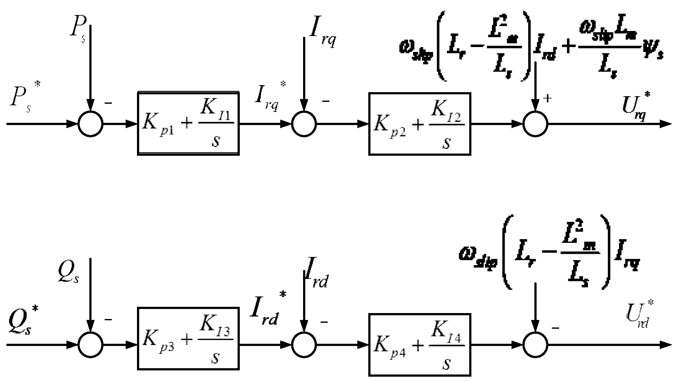
In Equation (17), the active and reactive power of the stator output can be controlled by the d-q component of the rotor current, and Figure 5 is the control strategy of the side converter.
As shown in Figure 5, DFIG’s rotor side converter uses a cascade control composed of a power loop and current loop to decouple the stator’s active and reactive power of DFIG. In the power loop, the reference value of the stator active power is given by the Maximum Power Point Tracking control (MPPT), while the reference value of reactive power is controlled by the wind farm.
3.2. Design of DFIG Active-Reactive Power Hybrid Additive Damping Controller
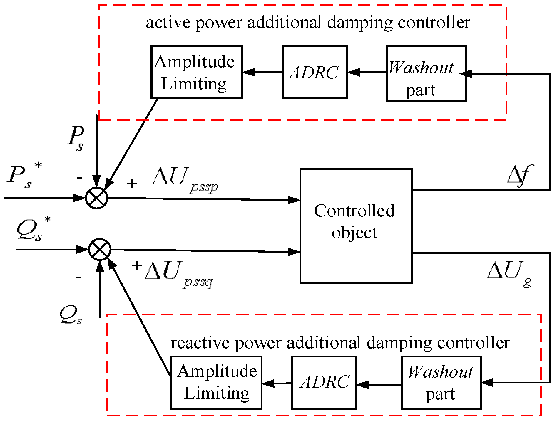
The electromechanical interaction of DFIG influences the transmission power between generators in an interconnected system. By controlling the d-q axis component of the DFIG rotor current, the active and reactive power of the stator can be controlled respectively, and then the power oscillation of the power system can be suppressed. In this paper, when the DFIG additional damping controller is designed, the frequency deviation of PCC is taken as the active power control signal, and the voltage deviation of PCC as the reactive power control signal, to improve the dynamic response of the reactive power on frequency deviation. The DFIG additional damping controller block diagram is shown in Figure 6. The input signal goes into the ADRC controller through a Washout to prevent the effects of the additional damping controller on the steady-state error.
To enhance the control accuracy, the N4SID subspace model identification method [33] is adopted in designing the ADRC. Firstly, a pulse signal is applied to the active additional damping controller output and the reactive additional damping controller output , and obtaining the input signal and of the controller. Next, obtain the state space model of the controlled object by N4SID and reduce it to a second order model according to the Hank singular value reduction theory. Based on the identification two order model as the known model, the ADRC additional damping controller is designed.
4. Simulation Analysis
4.1. Basic Parameters of the System
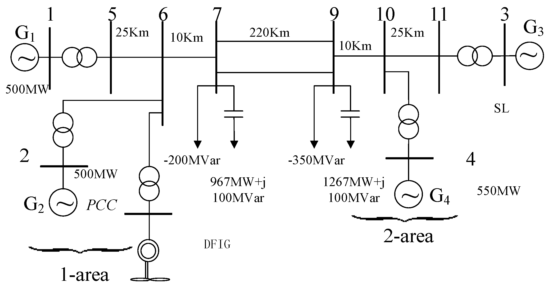
To verify the effectiveness of the proposed controller, the 2-area 4-machine system [34] with DFIG wind farm is built in DIgSILENT, as shown in Figure 7. The base capacity of the system is 100 mVA, the frequency is 50 Hz, the PSS is not added, and G3 is the balance machine. The wind farms are connected to the power grid on bus 6.
For simplification, the single-machine model is used as the lumped model of the wind farm to replace the whole wind farm. The specific parameters of DFIG are shown in the Appendix A. Table 1 is the interarea oscillation mode.
In the 2-area 4-machine system, exerting pulse signal with duration of 0.5 s at of the active power ring shown in Figure 6, taking and the frequency deviation signal at PCC point as the input and output signals of the controlled object. To identify a discrete linear time invariant state space model through the N4SID, and at last the second order transfer function model is noted as follows:
The dominant mode is , the frequency is 0.5795 Hz, Figure 8 is the impulse response curve of the two order after identification and the original system. It is obvious that the identification results satisfy the needs of the ADRC. The uncertain part of the model can be used as a disturbance to compensate for ADRC.
In the same way, the identification model of the reactive power additional damping control system is as follows:
Finally, the identified two-order model and are used as the known model into the ESO and compensation link of ADRC, and the simulation is carried out.
4.2. Parameter Tuning of ADRC
The control performance of ADRC mainly depends on its parameters. Once the parameters are determined, the controlled object changes in a certain range, which will not affect the control performance. The parameters of the two order ADRC selected in this paper mainly include TD’s parameters , ECO’s parameters , and NLSEF’s parameters . The three main parts of ADRC, TD, ESO, and NLSEF, are designed independently. They can be designed by using the “separation principle”. Through a large number of simulation experiments, the principles of parameter tuning are obtained as follows.
- 1.
- The principle of TD’s parameter tuning
The controlled input signal and of the ADRC additional damping controller designed in this paper need to maintain zero in steady state, so the input value of TD is . The speed factor determines the tracking response time of TD in depressing the overshoot of the system, generally taken as . The smaller the is, the more conducive to depressing overshoot, but when it is too small, it will also affect the response speed of the system. Therefore, take in this paper. About and , steady-state flutter can be eliminated as long as , so the simulation step length is , .
- 2.
- The principle of ESOs parameter tuning
A large number of simulations show that the parameters of ESO generally being as , , , which can meet the control requirements. When taking according to the concept of bandwidth [35], , , . is obtained according to the result of parameter identification, and is adjusted appropriately in simulation to achieve the best control effect.
- 3.
- The principle of NLSFE’s parameter tuning
The “error feedback” parameters are taken as follows:
The above parameters are properly adjusted in the DIgSILENT to ensure the control effect of ADRC.
4.3. Simulations and Analysis Under Different Circumstances
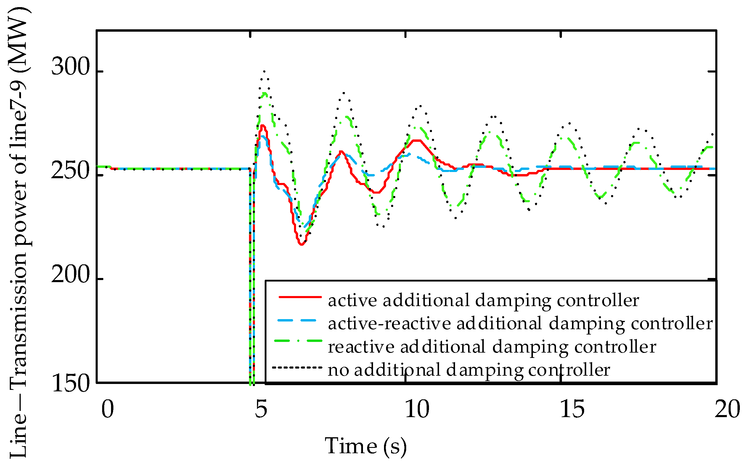
4.3.1. Simulation 1: Three Phase Short Circuit in Line 7–9 at 5.0 s and the Fault Disappears after 0.1 s
Figure 9 is a dynamic response diagram of transmission power of line 7–9 under four schemes, including active additional damping control, reactive additional damping control, active-reactive additional damping control, and no control.
It can be seen from Figure 9 that the short circuit fault causes the continuous oscillation of the power system. Under the action of active additional damping controller, the system is restored to stability in 7 s. Under the action of active-reactive additional damping controller, the oscillation attenuation time of line 7–9 transmission power reduces to 5 s, which has obvious inhibitory effect on power oscillation, and the control effect is better than the active or reactive additional damping control.
Figure 10a–d gives the dynamic response diagram of the total active power output of DFIG, total reactive power output of DFIG, rotor speed and DC side voltage under four schemes.
According to Figure 10a–d, the active additional damping controller needs to adjust its stator active power to suppress the fluctuation of at PCC, so as to avoid causing the fluctuation of the speed. Meanwhile, the active power mismatch on both sides of the DC bus leads to the unstable DC voltage. Therefore, a crowbar protection circuit should be put into operation to avoid rotor side converter overcurrent. At the same time, DC side load circuit is used to protect DC capacitance, preventing the DC voltage from exceeding the limit. When the reactive additional damping controller acts, DFIG adjusts the output of stator reactive power , making the voltage at the connection point of the wind farm stabilize rapidly. Thus the amplitude and the time of the power oscillation are reduced.
Due to the vector control of the Generation-side Converter, the variation of reactive power caused by the decoupling of active power and reactive power has little effect on the rotor speed and DC voltage of DFIG. However, the active-reactive additional damping controller enjoys both of the dynamic responses of the active additional damping controller and the reactive additional damping controller. From Figure 10, it can be seen that DFIG’s total active power output, total reactive power output, rotor speed, and DC side voltage are smaller than those of a single additional damping controller.
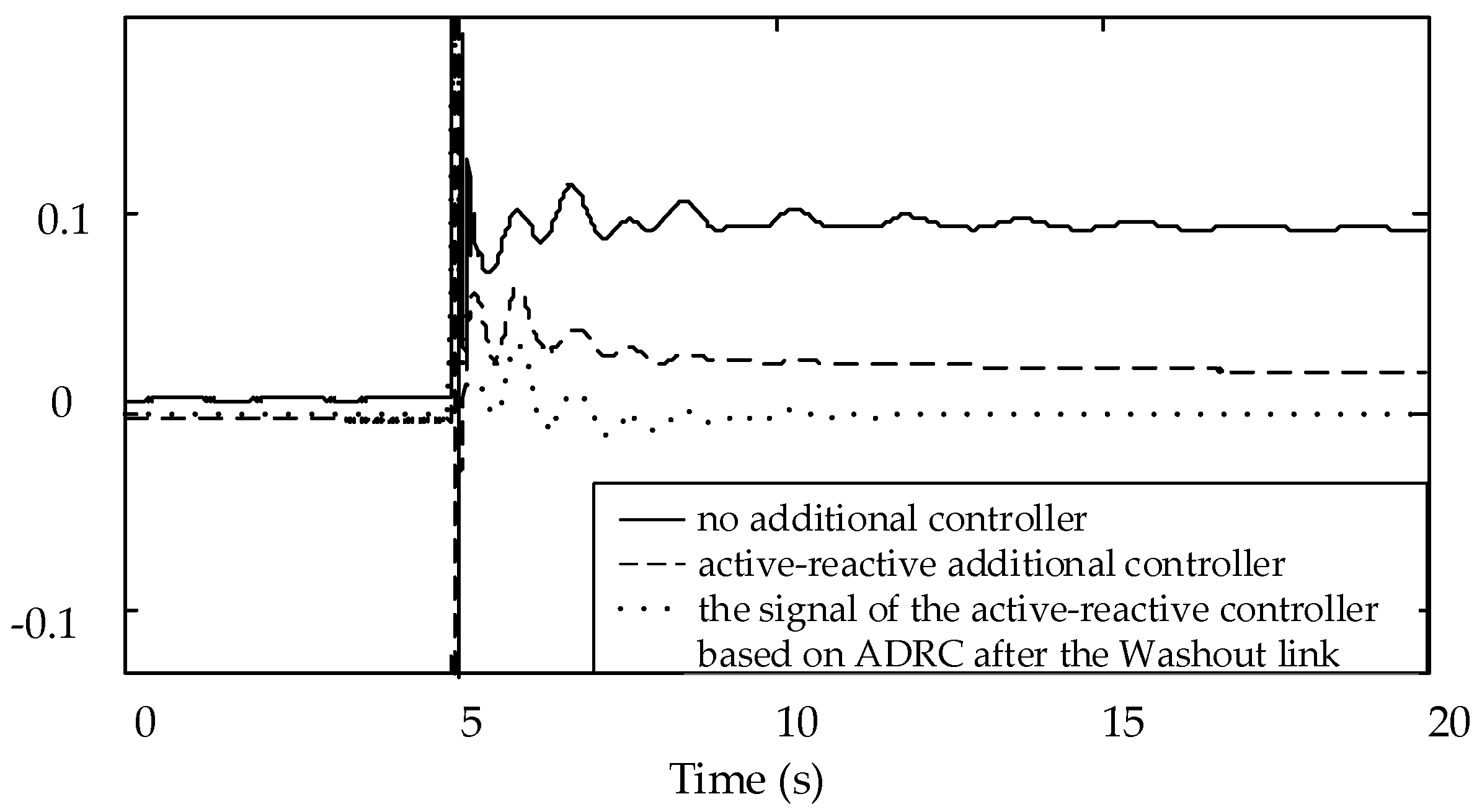
Figure 11 is the dynamic response diagram of the ADRC input signal and frequency deviation at PCC point. Figure 12 is a dynamic response diagram of the PCC point after the active-reactive additional damping controller acts with or without Washout link.
It can be seen from Figure 11 that without the controller, the frequency increases when a three-phase short circuit occurs on the line 7–9. Being a short simulation time, the system starts primary frequency regulation only without the secondary frequency regulation. Without the washout in the ADRC additional damping controller, as shown in Figure 12, the stability point of the frequency deviation at PCC point is zero, which indicates that the ADRC plays part of the role in secondary frequency regulation and increases the burden of the controller. Therefore, in order to avoid the secondary frequency regulation of the designed controller, the ADRC additional damping controller must join the Washout link.
4.3.2. Simulation 2: Line 7–9 is a Single Circuit, and There Is a Three Phase Short Circuit at 5.0 s and the Fault Disappears after 0.1 s
Assume that line 7–9 is a single circuit, and the damping ratio of the interarea oscillation mode is 0.02108 by the eigenvalue analysis. When applying the active-reactive additional damping controller to the system, Figure 13 shows a dynamic response diagram of the transmission power of the line 7–9 under the four schemes.
From Figure 13, it can be seen that without an additional damping controller, the amplitude of the power oscillation of the transmission line is still very large at 20 s because of the weak electrical connections between regions. Under the action of the active-reactive additional damping controller, the oscillation attenuation time is reduced to 5 s, the control effect is verified. It is proved that the active-reactive additional damping controller based on ADRC has good robustness and still has better control performance when the power system parameters change greatly.
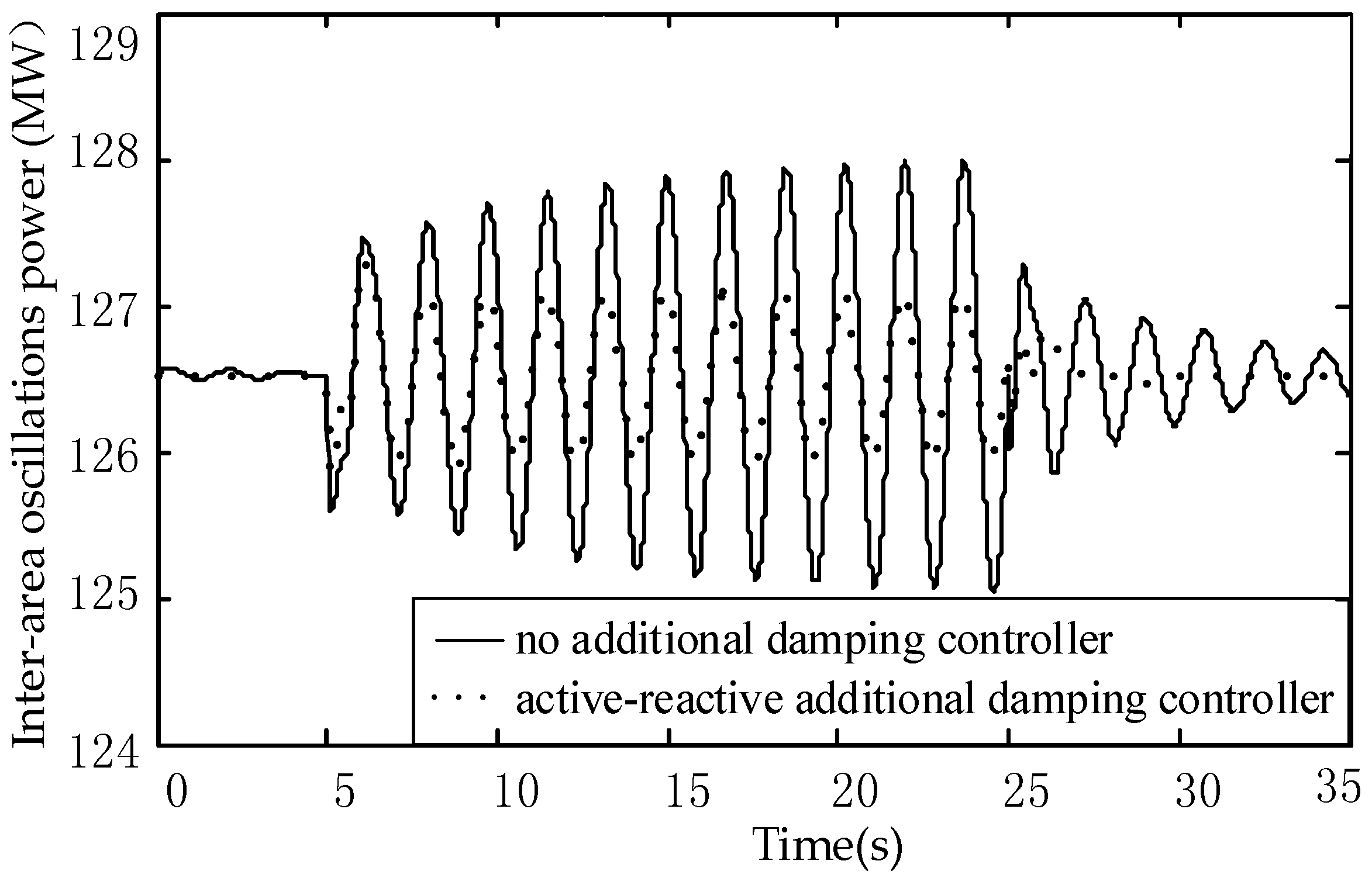
4.3.3. Simulation 3: Perturbation on DFIG Electromagnetic Torque
At 5.0 s, a small disturbance (given as 0.1sin(0.574t) with a frequency of interarea oscillations is applied to the DFIG electromagnetic torque to excite the forced power oscillation, and the duration of the disturbance is 20 s. The simulation results are shown in Figure 14.
Figure 14 shows that under the action of an active-reactive additional damping controller, the amplitude of the forced power oscillation reduces to 1/2 of the original. When the disturbance disappears, the system reaches the stability around 3 s. Therefore, the active-reactive additional damping controller significantly improves the damping, and has a good performance in suppressing the LFO and forced power oscillation.
4.3.4. Simulation 4: Comparisons between Traditional PID Control and ADRC Controller
Replacing the ADRC controller in Figure 6 to the traditional PID controller shown in Figure 15, setting up a three-phase short circuit fault with a duration of 0.1 s in line 7–9 at 5.0 s. Figure 16 and Figure 17 show the dynamic response comparisons diagram of the transmission power in two operating modes: line 7–9 is a single line while another one is the double lines.
As show in Figure 16, a system equipped with the additional damping controller based on ADRC reaches the steady state in around 5 s in two operating modes. In contrast, a system equipped with a PID controller becomes steady around 10 s with a double circuit line, and fails to stabilize within 15 s with a single circuit line. Conclusions can be drawn that the ability of the PID damping controller in suppressing LFO is weakened due to the change of the system operation mode, which also proves that the ADRC designed in this paper enjoys a higher level of robustness.
5. Conclusions
In this paper, the N4SID subspace identification method is proposed to improve the control effect of the ADRC, and the DFIG active-reactive power additional damping controller is obtained by using the improved ADRC algorithm. By using the N4SID combined with input and output data identification, the second order data model of the controlled object is built and embedded to the ESO and the dynamic compensation linearization part of the ADRC, which alleviates the burden of the observer and improves the accuracy of ADRC.
The transient simulation of the 2-area 4-machine system with wind farm is carried out to verify the control effect of the damping controller designed in this paper. In simulation 1 and 2, the operation state of the system is variable: in one case, line 7–9 is a double circuit while another one is a single circuit and the validity of the damping controller is verified. The results show that under different operational states of the system, it can still effectively restrain the LFO of the system.
Via the simulation 1, 2, and 3, it proves that the designed active-reactive power additional damping controller maintains a good control effect on the negative damping LFO and the forced power oscillation of the power system. At the same time, it is proved by simulation 4 that the ADRC controller in this paper is more robust and effective than the PID damping controller.
In a word, the DFIG active-reactive power additional damping controller based on ADRC performs well in suppressing the LFO of the system with the ability of being adaptive to the variation of the power system. It can provide effective reference and help for the suppression of LFO of grid-connected wind turbines.
Author Contributions
Y.M. conceived and designed the experiments; J.L. performed the experiments in the DIgSILENT; Y.M. and J.L. analyzed the data; J.L. and H.L. wrote the paper. S.Z. provided the wind farm data.
Acknowledgments
The authors thank the anonymous referees for their helpful comments and suggestions. This work was supported in part by Hebei Natural Science Foundation (grant numbers: E2017502077), in part by Central colleges and Universities (grant numbers: 2016MS86).
Conflicts of Interest
The authors declare no conflict of interest.
Appendix A

Table A1.
DFIG electrical parameters.
| No. | Variable | Description | Company | Reference Value |
|---|---|---|---|---|
| 1 | rated mechanical power | MW | 5 | |
| 2 | rated voltage | kV | 0.69 | |
| 3 | rated frequency | Hz | 50 | |
| 4 | stator resistance | p.u. | 0.003 | |
| 5 | stator reactance | p.u. | 0.125 | |
| 6 | rotor resistance | p.u. | 0.004 | |
| 7 | rotor reactance | p.u. | 0.05 | |
| 8 | excitation reactance | p.u. | 2.5 | |
| 9 | rotational inertia coefficient of wind wheel | 3 | ||
| 10 | pitch control gain | p.u. | 100 | |
| 11 | pitch control time constant | s | 1 | |
| 14 | wind wheel radius | m | 50 |
References
- Singh, M.; Allen, A.J.; Muljadi, E.; Gevorgian, V.; Zhang, Y.; Santoso, S. Interarea Oscillation Damping Controls for Wind Power Plants. IEEE Trans. Sustain. Energy 2015, 6, 967–975. [Google Scholar] [CrossRef]
- Xi, X.Z.; Geng, H.; Yang, G. Modelling of the DFIG based wind farms for small signal stability analysis of weak power grids. In Proceedings of the 2nd IET Renewable Power Generation Conference, Beijing, China, 9–11 September 2013; IET: Stevenage, UK, 2013. [Google Scholar]
- Chandrasekhar, A.; Alluri, N.R.; Sudhakaran, M.S.P.; Mok, Y.S.; Kim, S.-J. A smart mobile pouch as a biomechanical energy harvester towards self-powered smart wirelesspower transfer applications. Nanoscale 2017, 9, 9818–9824. [Google Scholar] [CrossRef] [PubMed]
- Borthwick, A.G.L. Marine Renewable Energy Seascape. Engineering 2016, 2, 69–78. [Google Scholar] [CrossRef]
- Global Wind Energy Council. Global Wind Report-Annual Markt Update 2016; Global Wind Energy Council: Brussels, Belgium, 2016; pp. 111–118. [Google Scholar]
- Failla, G.; Arena, F. New perspectives in offshore wind energy. Philos. Trans. R. Soc. A Math. Phys. Eng. Sci. 2015, 373, 20140228. [Google Scholar] [CrossRef] [PubMed]
- Xi, X.Z.; Geng, H.; Yang, G. Small Signal Stability of Weak Power System Integrated with Inertia Tuned Large Scale Wind Farm. In Proceedings of the 2014 IEEE Innovative Smart Grid Technologies-Asia (ISGT Asia), Kuala Lumpur, Malaysia, 20–23 May 2014; 2014; pp. 514–518. [Google Scholar] [CrossRef]
- Xi, X.Z.; Geng, H.; Yang, G. Enhanced model of the doubly fed induction generator-based wind farm for small-signal stability studies of weak power system. IET Renew. Power Gen. 2014, 8, 765–774. [Google Scholar] [CrossRef]
- Miao, Z.X.; Fan, L.L.; Osborn, D.; Yuvarajan, S. Control of DFIG-Based Wind Generation to Improve Interarea Oscillation Damping. IEEE Trans. Energy Convers. 2009, 24, 415–422. [Google Scholar] [CrossRef]
- Tsourakis, G.; Nomikos, B.M.; Vournas, C.D. Contribution of Doubly Fed Wind Generators to Oscillation Damping. IEEE Trans. Energy Convers. 2009, 24, 783–791. [Google Scholar] [CrossRef]
- Fan, L.L.; Yin, H.P.; Miao, Z.X. On Active/Reactive Power Modulation of DFIG-Based Wind Generation for Interarea Oscillation Damping. IEEE Trans. Energy Convers. 2011, 26, 513–521. [Google Scholar] [CrossRef]
- Mishra, Y.; Mishra, S.; Tripathy, M.; Senroy, N.; Dong, Z.Y. Improving Stability of a DFIG-Based Wind Power System with Tuned Damping Controller. IEEE Trans. Energy Convers. 2009, 24, 650–660. [Google Scholar] [CrossRef]
- Mishra, Y.; Mishra, S.; Li, F.X.; Dong, Z.Y.; Bansal, R.C. Small-Signal Stability Analysis of a DFIG-Based Wind Power System Under Different Modes of Operation. IEEE Trans. Energy Convers. 2009, 24, 972–982. [Google Scholar] [CrossRef]
- Yang, L.H.; Xu, Z.; Østergaard, J.; Dong, Z.Y.; Wong, K.P.; Ma, X. Oscillatory Stability and Eigenvalue Sensitivity Analysis of A DFIG Wind Turbine System. IEEE Trans. Energy Convers. 2011, 26, 328–339. [Google Scholar] [CrossRef] [Green Version]
- Heniche, A.; Kamwa, I. Assessment of two methods to select wide-area signals for power system damping control. IEEE Trans. Power Syst. 2008, 23, 572–581. [Google Scholar] [CrossRef]
- Chau, T.K.; Yu, S.S.; Fernando, T.L.; Lu, H.H.-C.; Small, M. A Novel Control Strategy of DFIG Wind Turbines in Complex Power Systems for Enhancement of Primary Frequency Response and LFOD. IEEE Trans. Power Syst. 2018, 33, 1811–1823. [Google Scholar] [CrossRef]
- Liao, K.; He, Z.Y.; Wang, Y.; Yang, J.W. An input-output linearization algorithm-based inter-area damping control strategy for DFIG. IEEJ Trans. Electr. Electr. Eng. 2018, 13, 32–37. [Google Scholar] [CrossRef]
- Geng, H.; Xi, X.Z.; Liu, L.; Yang, G.; Ma, J. Hybrid Modulated Active Damping Control for DFIG-Based Wind Farm Participating in Frequency Response. IEEE Trans. Energy Convers. 2017, 32, 1220–1230. [Google Scholar] [CrossRef]
- Hui, L.; Liu, S.Q.; Ji, H.T.; Yang, D.; Yang, C.; Chen, H.W.; Zhao, B.; Hu, Y.G.; Chen, Z. Damping control strategies of inter-area low-frequency oscillation for DFIG-based wind farms integrated into a power system. Int. J. Electr. Power 2014, 61, 279–287. [Google Scholar] [CrossRef]
- Mendonca, A.; Lopes, J.A.P. Robust tuning of power system stabilisers to install in wind energy conversion systems. IET Renew. Power Gen. 2009, 3, 465–475. [Google Scholar] [CrossRef]
- Hughes, F.M.; Anaya-Lara, O.; Jenkins, N.; Strbac, G. A power system stabilizer for DFIG-based wind generation. IEEE Trans. Power Syst. 2018, 21, 763–772. [Google Scholar] [CrossRef]
- Geng, H.; Xu, D.W.; Wu, B.; Yang, G. Active Damping for PMSG-Based WECS with DC-Link Current Estimation. IEEE Trans. Ind. Electron. 2011, 58, 1110–1119. [Google Scholar] [CrossRef]
- Geng, H.; Xu, D.; Wu, B.; Yang, G. Comparison of oscillation damping capability in three power control strategies for PMSG-based WECS. Wind Energy 2011, 14, 389–406. [Google Scholar] [CrossRef]
- Liao, K.; He, Z.Y.; Xu, Y.; Chen, G.; Dong, Z.Y.; Wong, K.P. A Sliding Mode Based Damping Control of DFIG for Interarea Power Oscillations. IEEE Trans. Sustain. Energy 2017, 8, 258–267. [Google Scholar] [CrossRef]
- Han, J. Auto-Disturbance Rejection Control and its Applications. Control Decis. Chin. 1998, 13, 19–23. [Google Scholar]
- Yang, J.; Cui, H.Y.; Li, S.H.; Zolotas, A. Optimized Active Disturbance Rejection Control for DC-DC Buck Converters with Uncertainties Using a Reduced-Order GPI Observer. IEEE Trans. Syst. I Regular Pap. 2018, 65, 832–841. [Google Scholar] [CrossRef]
- Yin, Z.G.; Du, C.; Liu, J.; Sun, X.D.; Zhong, Y.R. Research on Autodisturbance-Rejection Control of Induction Motors Based on an Ant Colony Optimization Algorithm. IEEE Trans. Ind. Electron. 2018, 65, 3077–3094. [Google Scholar] [CrossRef]
- Liu, D.; Che, C.; Zhou, Z. Permanent magnet synchronous motor control system based on auto disturbances rejection controller. In Proceedings of the 2011 International Conference on Mechatronic Science, Electric Engineering and Computer (MEC 2011), Jilin, China, 19–22 August 2011. [Google Scholar]
- Li, J.; Ren, H.P.; Zhong, Y.R. Robust Speed Control of Induction Motor Drives Using First-Order Auto-Disturbance Rejection Controllers. IEEE Trans. Ind. Appl. 2015, 51, 712–720. [Google Scholar] [CrossRef]
- Zhang, G.Q.; Wang, G.L.; Yuan, B.H.; Liu, R.; Xu, D.X. Active Disturbance Rejection Control Strategy for Signal Injection-Based Sensorless IPMSM Drives. IEEE Trans. Transp. Electr. 2018, 4, 330–339. [Google Scholar] [CrossRef]
- Han, J. From PID to active disturbance rejection control. IEEE Trans. Ind. Electron. 2009, 56, 900–906. [Google Scholar] [CrossRef]
- Altun, H.; Sunter, S. Modeling, simulation and control of wind turbine driven doubly-fed induction generator with matrix converter on the rotor side. Electr. Eng. 2013, 95, 157–170. [Google Scholar] [CrossRef]
- Katayama, T. Subspace methods for system identification. Automatica 2007, 43, 748–749. [Google Scholar] [CrossRef]
- Kundur, P. Power System Stability and Control; McGraw-Hill: New York, NY, USA, 1994. [Google Scholar]
- Zhiqiang, G. Scaling and bandwidth parameterization based controller-tuning. In Proceedings of the 2003 American Control Conference, Denver, CO, USA, 4–6 June 2003; pp. 4989–4996. [Google Scholar]
Figure 1.
Active disturbance rejection control (ADRC) diagram.

Figure 2.
Disturbance observer error transfer function amplitude-frequency response curve.

Figure 3.
The schematic diagram of simplified structure for doubly fed induction generator (DFIG).

Figure 4.
Stator flux orientation vector.

Figure 5.
Generator side converter control strategy.

Figure 6.
DFIG active—reactive additional damping controller block diagram.

Figure 7.
The simulation diagram of 2-area 4-machine system with DFIG wind farm.

Figure 8.
Impulsive response curve.
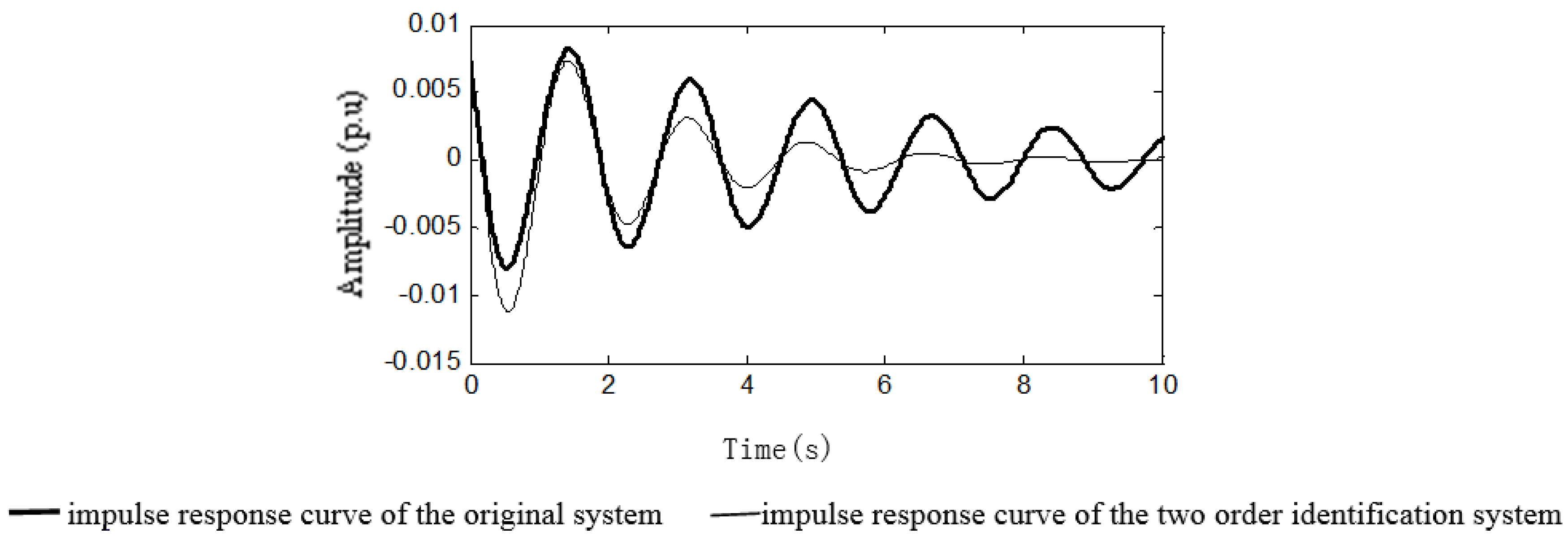
Figure 9.
Transmission power of line 7–9.
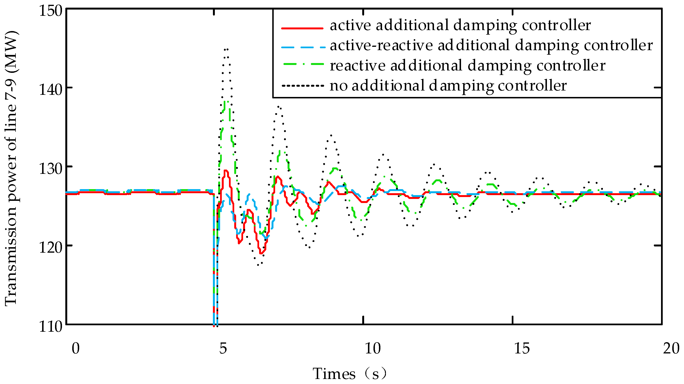
Figure 10.
Double Circuit Line—DFIG dynamic response with line 7–9 three-phase short circuit fault.
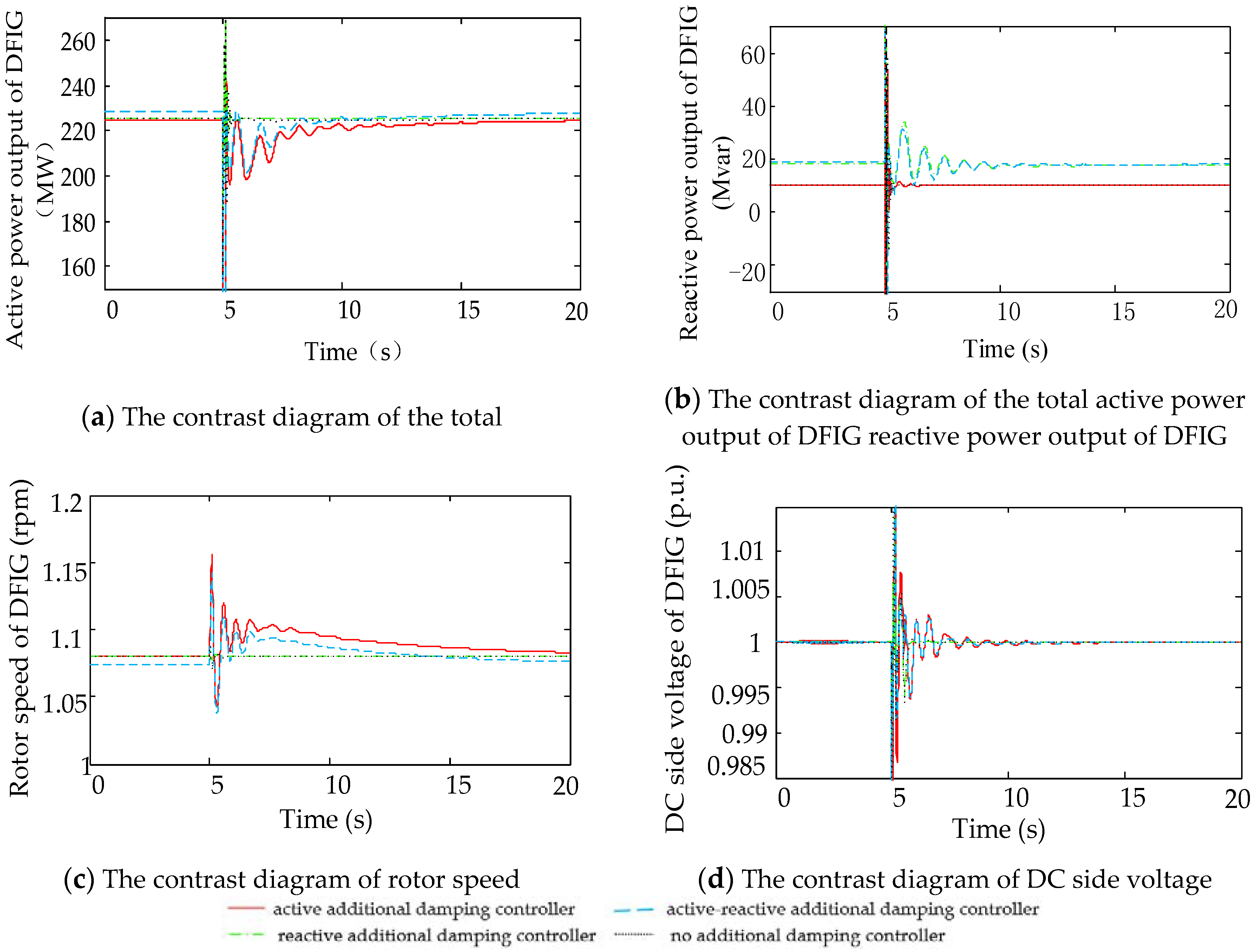
Figure 11.
Input signal of ADRC and of PCC.

Figure 12.
Frequency deviation of PCC.
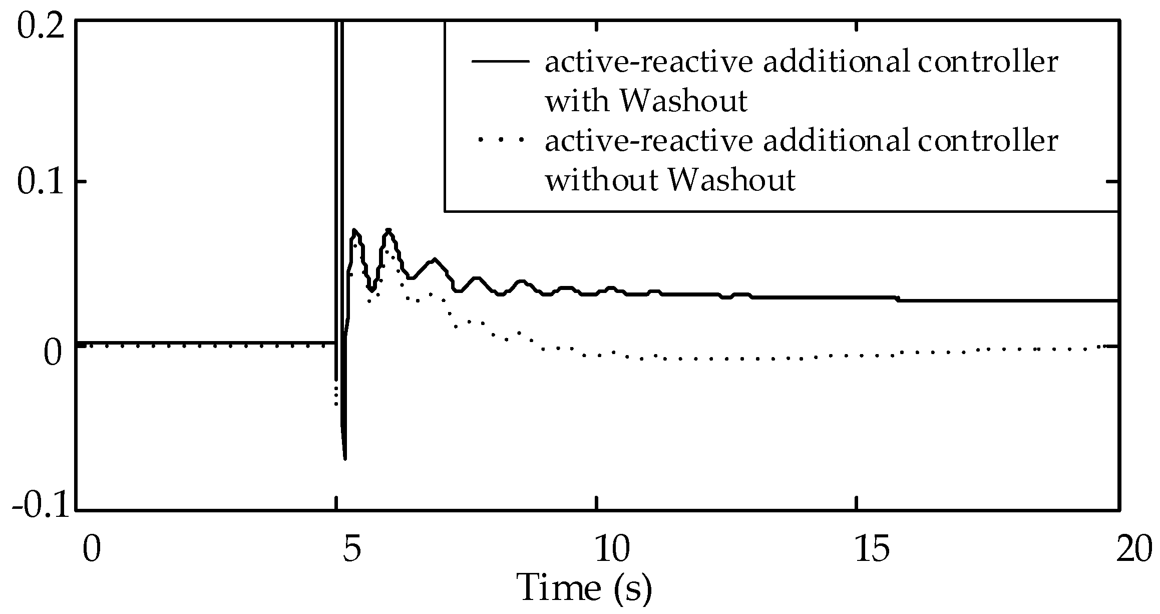
Figure 13.
Single Circuit Line—Transmission power of line 7–9.

Figure 14.
Forced Power Oscillation comparison chart.

Figure 15.
Traditional proportional–integral–derivative (PID) block diagram.
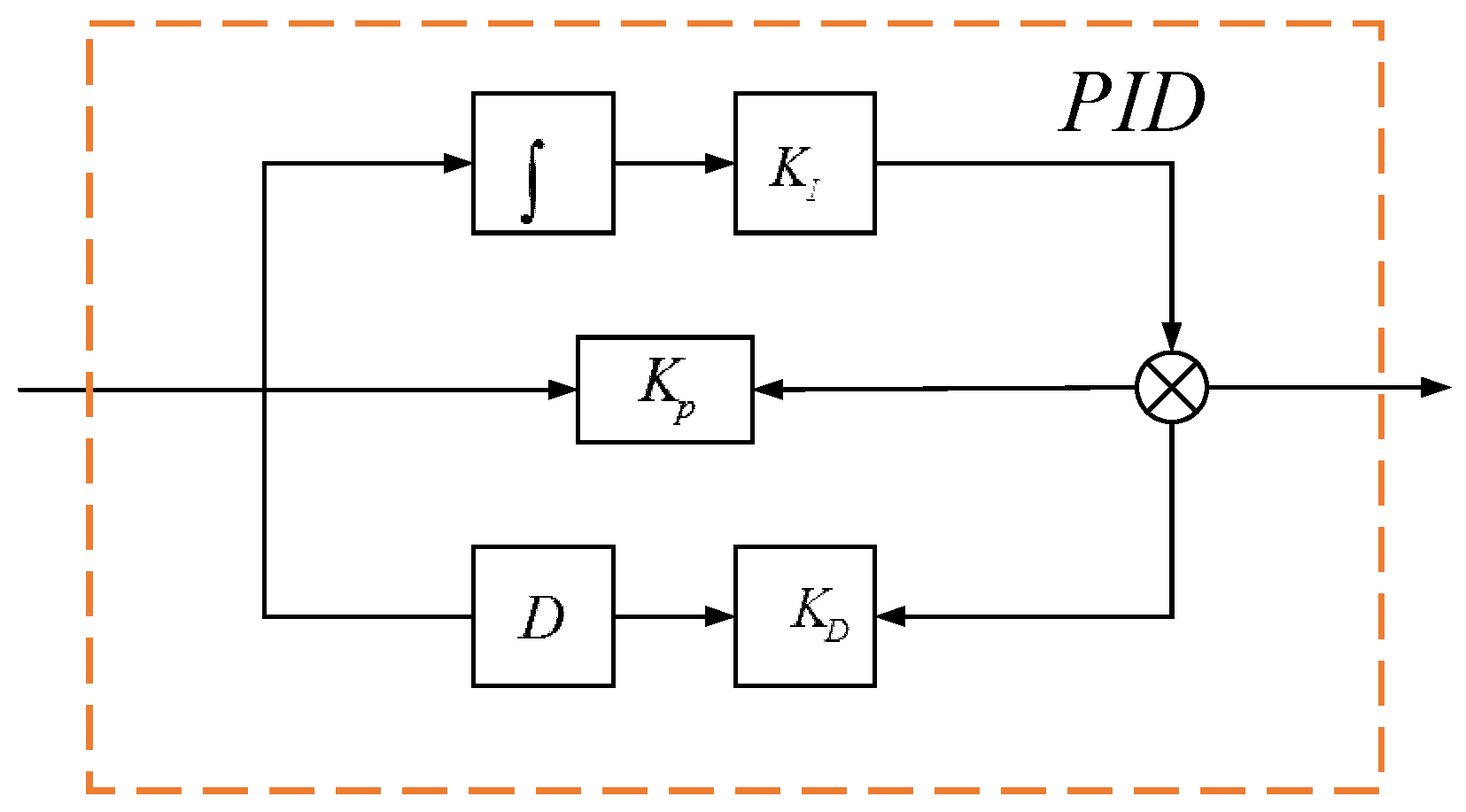
Figure 16.
Double Circuit Line—Transmission power of line 7–9.
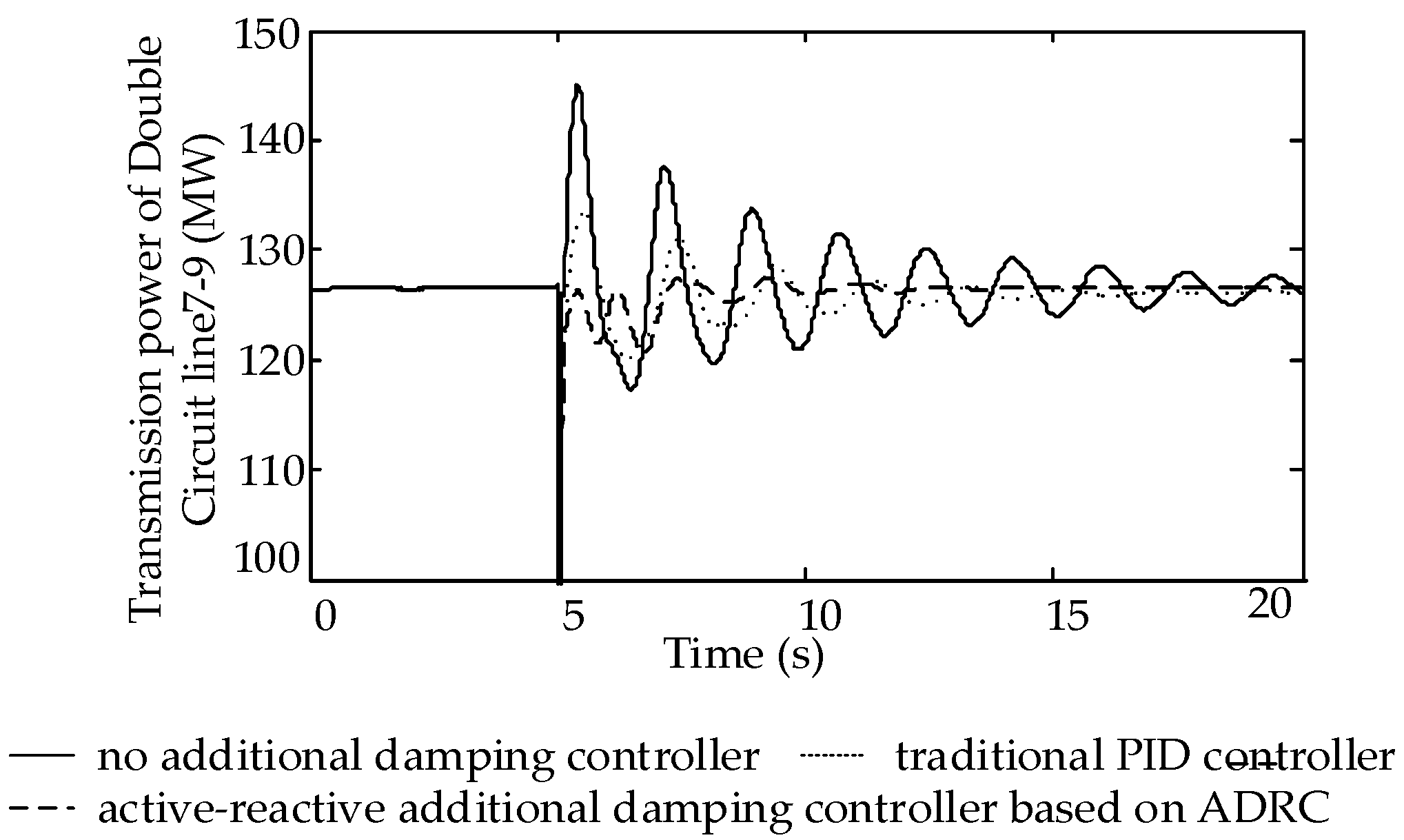
Figure 17.
Single Circuit Line—Transmission power of line 7–9.
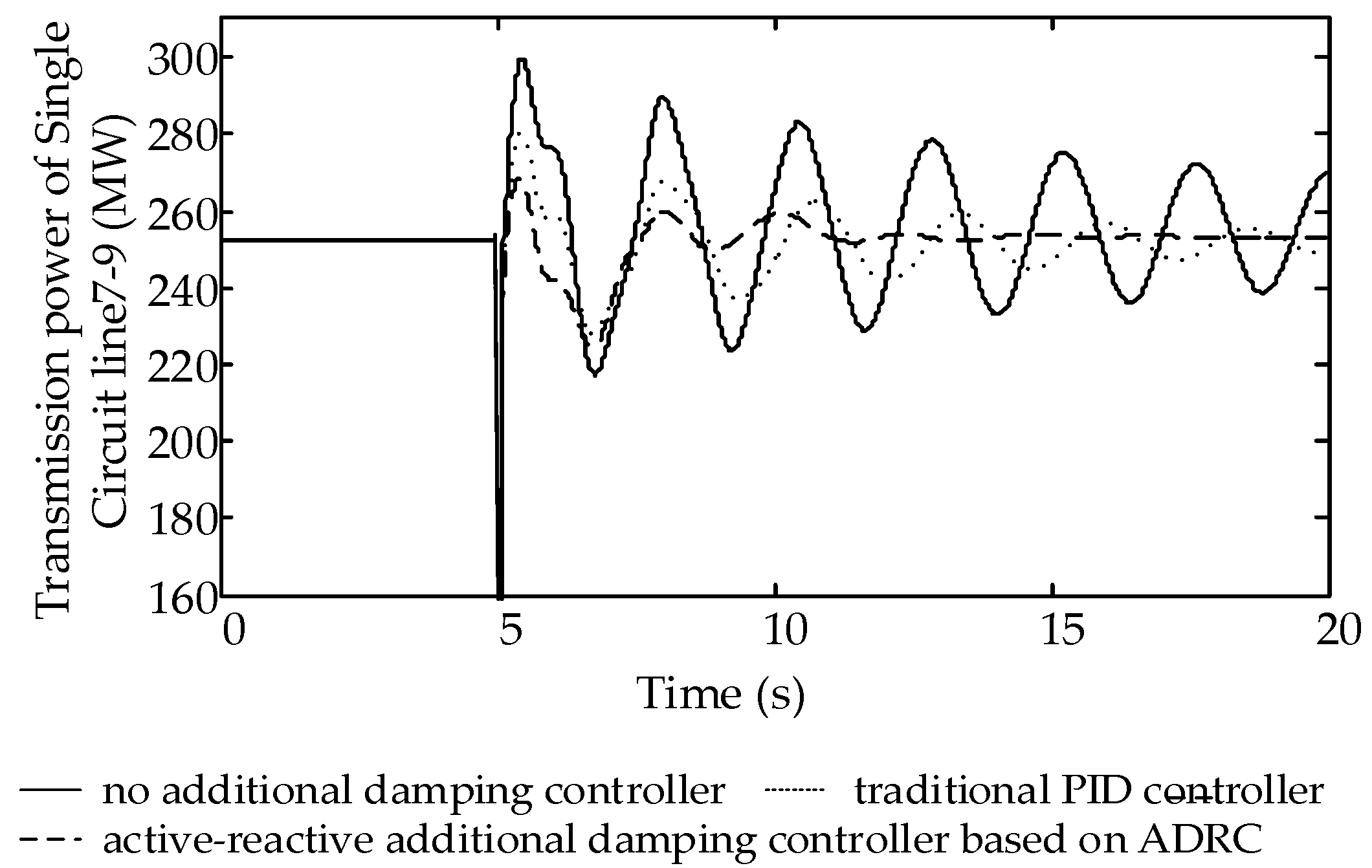
Table 1.
Interarea oscillation mode of 4 machines 2 areas.
| Real Part | Imaginary Part | Frequency (Hz) | Damping Ratio |
|---|---|---|---|
| −0.1710 | 3.6067 | 0.5740 | 0.0474 |
© 2018 by the authors. Licensee MDPI, Basel, Switzerland. This article is an open access article distributed under the terms and conditions of the Creative Commons Attribution (CC BY) license (http://creativecommons.org/licenses/by/4.0/).
Share and Cite
MDPI and ACS Style
Ma, Y.; Liu, J.; Liu, H.; Zhao, S. Active-Reactive Additional Damping Control of a Doubly-Fed Induction Generator Based on Active Disturbance Rejection Control. Energies 2018, 11, 1314. https://doi.org/10.3390/en11051314
AMA Style
Ma Y, Liu J, Liu H, Zhao S. Active-Reactive Additional Damping Control of a Doubly-Fed Induction Generator Based on Active Disturbance Rejection Control. Energies. 2018; 11(5):1314. https://doi.org/10.3390/en11051314
Chicago/Turabian StyleMa, Yanfeng, Jia Liu, Haihang Liu, and Shuqiang Zhao. 2018. "Active-Reactive Additional Damping Control of a Doubly-Fed Induction Generator Based on Active Disturbance Rejection Control" Energies 11, no. 5: 1314. https://doi.org/10.3390/en11051314
Note that from the first issue of 2016, this journal uses article numbers instead of page numbers. See further details here.