Review

Review of Voltage and Frequency Grid Code Specifications for Electrical Energy Storage Applications

1
School of Engineering, University of Warwick, Coventry CV4 7AL, UK
2
UK National Grid, Warwick CV34 6DA, UK
3
School of Electrical & Electronic Engineering, Huazhong University of Science & Technology, Wuhan 430074, China
*
Authors to whom correspondence should be addressed.
Energies 2018, 11(5), 1070; https://doi.org/10.3390/en11051070
Submission received: 12 April 2018 / Revised: 20 April 2018 / Accepted: 24 April 2018 / Published: 26 April 2018
(This article belongs to the Section F: Electrical Engineering)

Abstract

:
To ensure the stability and reliability of the power network operation, a number of Grid Codes have been used to specify the technical boundary requirements for different countries and areas. With the fast propagation of the usage of Electrical Energy Storage (EES), it is quite important to study how the EES technology with its development can help the Grid Code realization. The paper provides a comprehensive study of Great Britain (GB) Grid Code mainly on its voltage and frequency relevant specifications, with a comparison of other countries’ grid operation regulations. The different types of EES technologies with their technical characteristics in relation to meeting Grid Codes have been analysed. From the study, apart from direct grid-connection to provide grid services on meeting Grid Codes, EES devices with different technologies can be used as auxiliary units in fossil-fuelled power plants and renewable generation to support the whole systems’ operation. The paper also evaluates the potentials of different types of EES technologies for implementing the relevant applications based on the Grid Codes. Some recommendations are given at the end, for the EES technology development to help the Grid Code realization and to support the relevant applications.

1. Introduction

A power network can be a quite complex system which is from electricity generation, transmission, and distribution to end-user consumption. To ensure the stability and reliability of such a system operation, a series of specifications entitled Grid Code normally issued by Transmission System Operators (TSOs) have been set and implemented to specify the technical boundary requirements relating to connections to, and the operation and use of, the electricity network [1]. The Grid Code involves many aspects of the power grid operation and thus its contents have a wide range. Electrical Energy Storage (EES) has been recognized as an important part of power networks in recent years because it can have multiple attractive functions to power networks, e.g., reducing CO2 and other greenhouse gas emissions, supporting meeting peak load demands, improving the electrical power quality and helping in the smart grid realization [2,3,4,5]. With the different EES technologies, EES systems can be used either as auxiliary facilities in power plants (including fossil-fuelled and renewable power generation) or as independent units in the power networks to support the Grid Code realization. Although in many countries the Grid Code has not been updated yet with EES specific prescriptions, the EES systems can be treated as electricity generation utilities in the grids when they are operated in the discharging mode with grid-connection. Thus, the examination of EES technical characteristics in relation to the current power network operation regulations is essential for the improvement of power network stability, the guidance of EES technology development and the Gide Code evolution with the fast propagation of renewable in power networks.
The study on the different EES technologies with the purpose of their implementations in compliance with the power network regulations, supporting the Grid Code realization and impacting its evolution is relatively lacking. So far, there are some good quality papers which have mainly focused on the review of the research and development of EES technologies with their power system applications. Amirante et al. provided a detailed overview of the state-of-the-art EES technologies, covering mechanical, electrochemical and hydrogen technologies [4]. The operation principles, technical and economic features of different EES options were analysed, and a schematic comparison among the potential utilization of EES systems was presented [4]. Robyns et al. [3] highlighted the challenge and the valuation of EES in transportation systems with concerned electrical power systems, e.g., local grids for applications in aviation, electrical vehicles, hybrid railway power substation systems and railway smart grid perspective. Gopstein reviewed the historical grid and the changing grid of today and claimed that EES can support a more flexible grid realization with improved system reliability and resilience [5]. In addition, the technical characteristics, utility-scale grid applications with their impacts, and the deployment of EES were discussed [5]. Whittingham discussed the importance of EES in the key application areas (including electronic devices, transportation, and utility grids), and predicted the EES capabilities in conjunction with the smart grid [6]. Luo et al. provided a comprehensive study of the recent development of EES technologies in both academic communities and industrial sectors [2]. The study was carried out based on the relevant technical and economic data, and the further discussion on the EES power system applications with their decision-making factors was also given [2]. From another point of view, some other articles reviewed the Grid Code technical requirements with different focuses, e.g., the international regulations and the current practices regarding the verification and certification of the electrical performance in renewable generation systems for grid connection [7], the requirements to generate assets with the influence of weakness and isolation of a power grid on the interconnection conditions [8], and the Fault Ride Through review concerning on photovoltaic systems to power networks [9]. From the above, the review work of Grid Codes in relation to the EES applications which are for supporting/achieving the power grid operating regulations’ realization is quite necessary.
This paper provides a comprehensive study mainly on the voltage and frequency Grid Code specifications, for investigating the relevant EES applications aiming to meet the grid operation regulations and also for guiding the corresponding technology development. This paper begins with an overview of the Grid Codes through a detailed study of Great Britain (GB) Grid Code with a comparison of many other countries’ grid operation regulations. Then, a technical analysis is performed to identify whether the EES technologies can meet the Grid Code requirements. This paper also evaluates the different EES technology application potentials for supporting the Grid Code realization, especially on frequency and voltage control. Finally, some recommendations are made for technology development, in terms of supporting the grid operation and helping the Grid Code evolution.

2. Overview of Grid Codes

The Grid Code differs considerably from one country to another, because they are directly related to the nature of generation characteristics and network operation requirement. For instance, the frequency response requirement is normally more stringent in a relatively isolated (i.e., weakly interconnected) system, such as the grid in Great Britain and Ireland, compared with a large and strongly interconnected system, such as the French transmission system in Continental Europe. Grid Code requirements were initially developed based on the conventional fossil-fuelled power plant operation characteristics and since then have been tailored to allow more different generation types connecting to the power network, for example, wind power generation. For managing the specific national grid systems and dealing with different situations including emergencies, TSOs set their own Grid Code specifications individually.
An overview of Grid Code requirements in different countries is presented in this section, mainly in the aspects of voltage levels, normal/critical frequencies with intervals and requirements to generating units. It should be noted that the national regulatory frameworks are subject to continuous changes and revisions.

2.1. Voltage Adopted by National Electricity Transmission

The GB Grid Code is applied to power networks with transmission voltage levels of 400, 275 and 132 kV (32 kV for Scotland) [1,7,10]. The national high-voltage transmission system is owned and maintained by three companies: National Grid (owns more than 14,000 circuit km of 400 kV and 275 kV overhead lines and cables), Scottish and Southern Energy (about 5000 circuit km of 275 kV and 132 kV overhead lines and cables) and Scottish Power (about 4000 circuit km of 400, 275 and 132 kV overhead lines and cables) [1]. Table 1 summarizes the operating ranges of the UK National Electricity Transmission System [1,10]. A summary of the transmission rated voltage levels in the national power networks in different countries is presented in Table 2. Germany is the only country that has issued the different voltage level for offshore grid-connection in Table 2. The transmission rated voltage information for some other countries, i.e., Spain, Czech Republic, and Canada, can be found in [11,12,13].

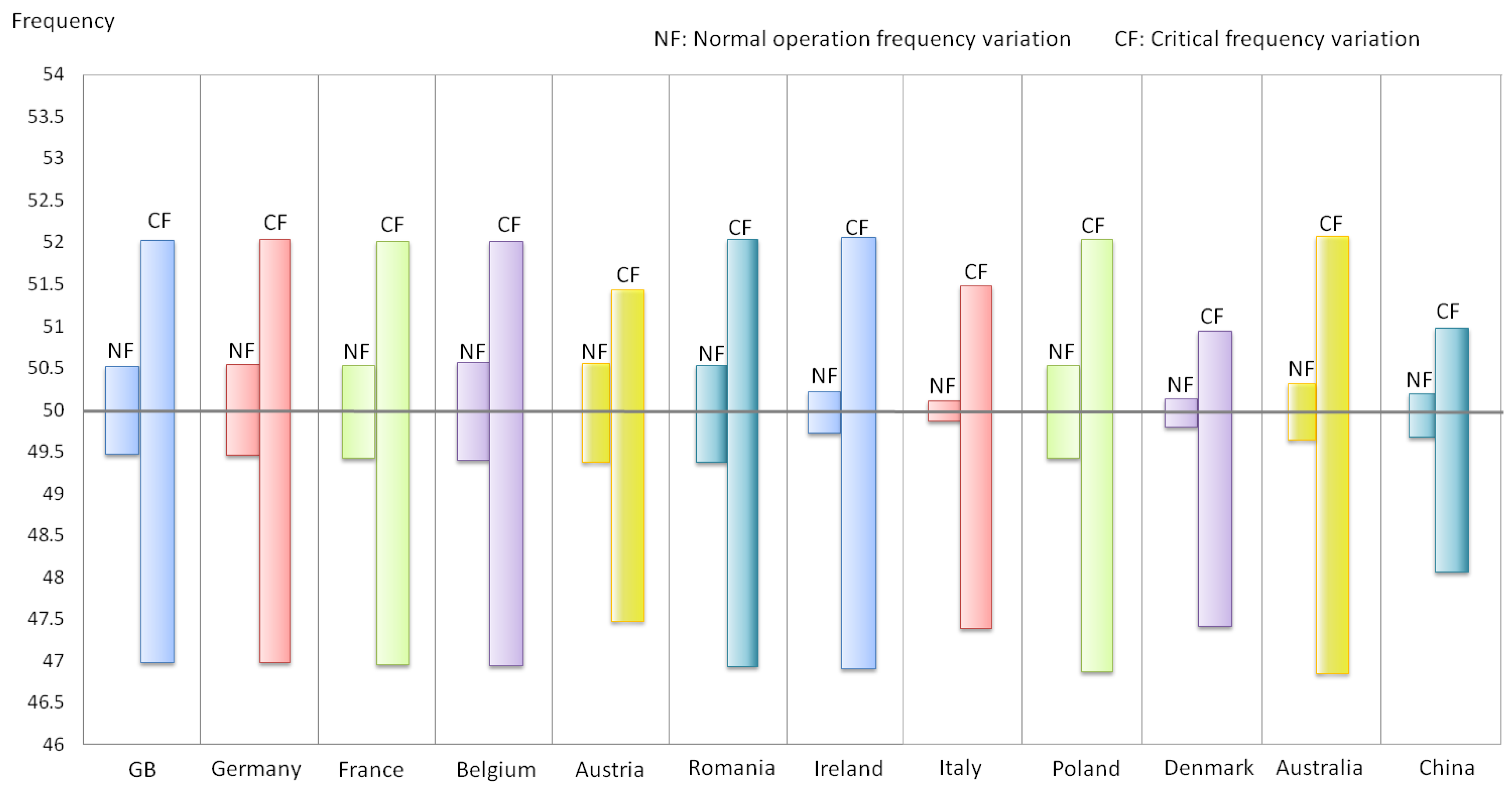
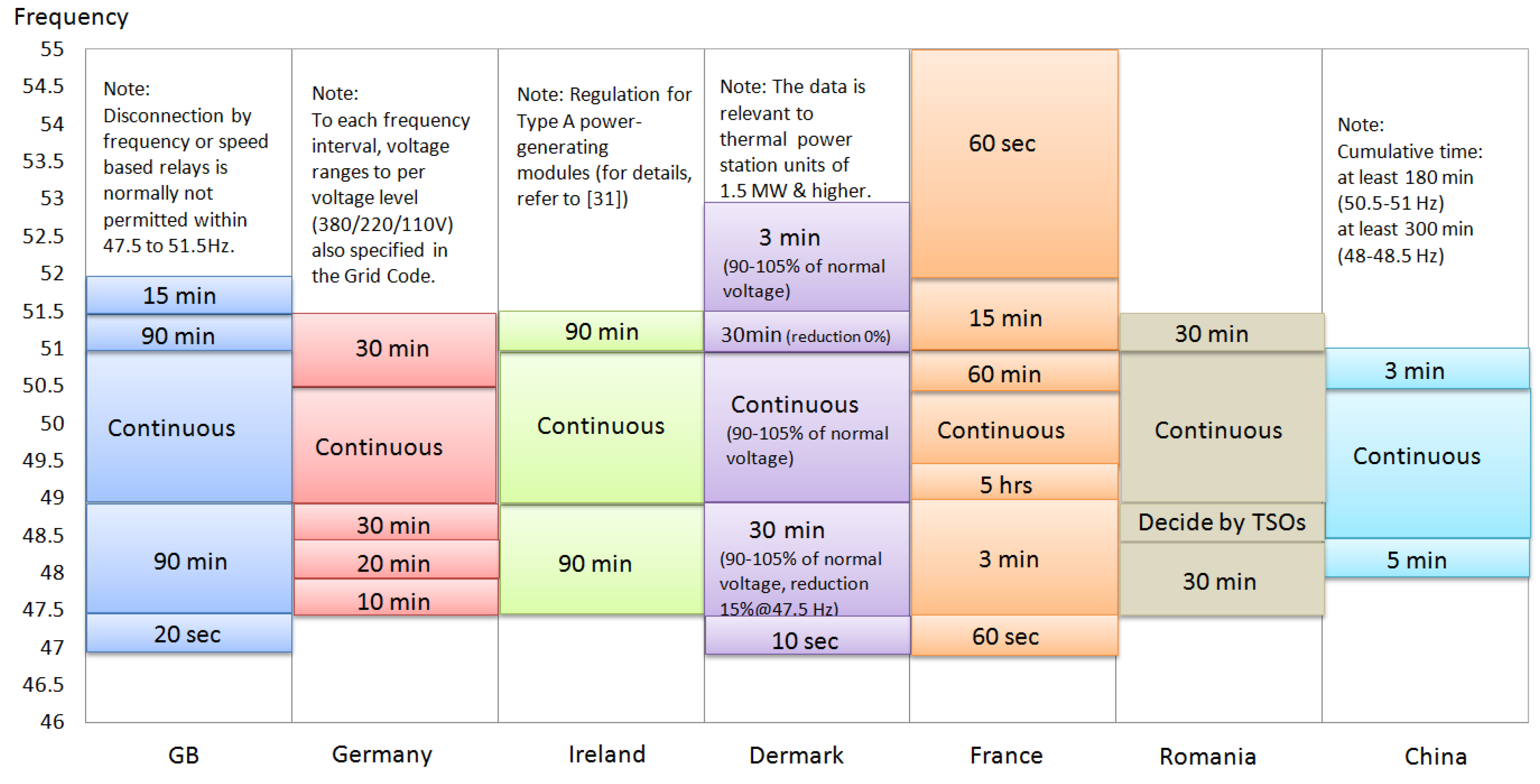
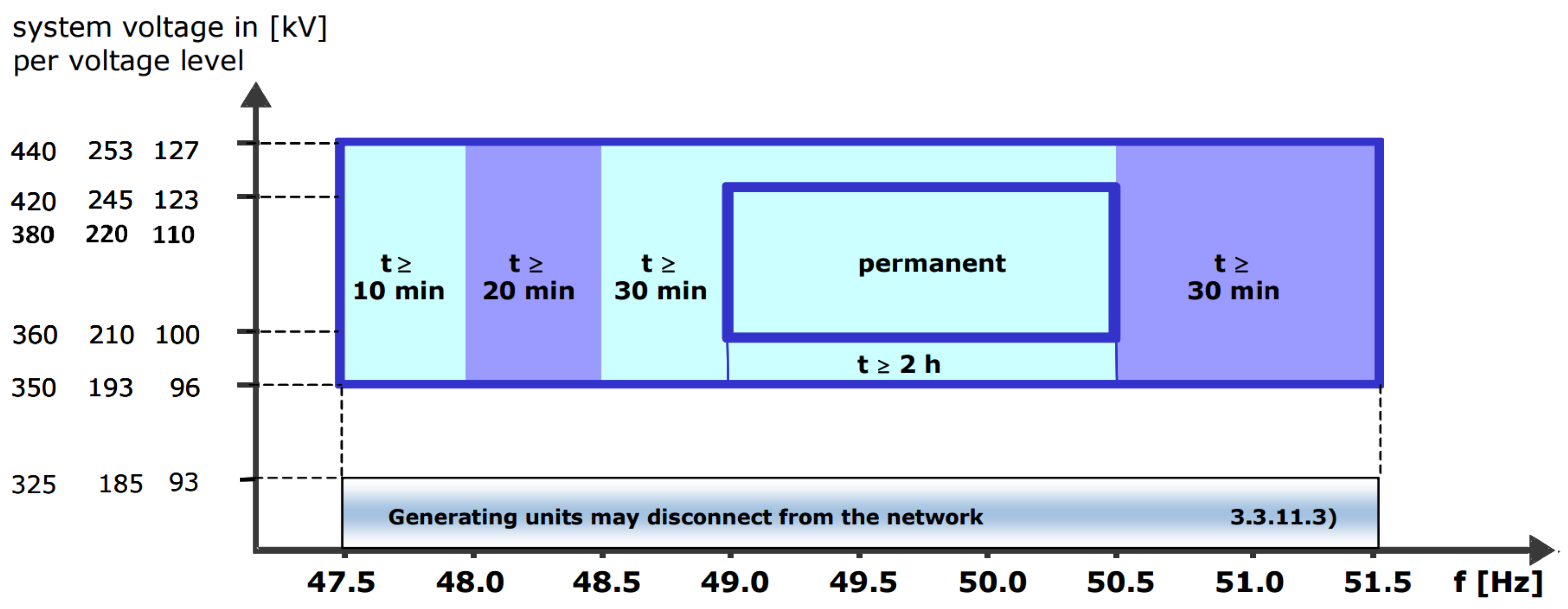
2.2. Normal and Critical Frequencies with Intervals Specified in Grid Codes

The majority of electrical power in the world is generated by fossil-fuelled power plants using synchronous generators. The electricity frequency control is achieved via regulating the generator’s rotor speed to synchronize with the grid frequency. If the balance between the electricity generation and load demand is broken, a power deviation will occur. This will cause the system frequency deviation from its set-point. Large frequency deviations can not only damage these generating units but also end-users’ machines. To prevent such an incident from occurring, power plant generators are normally equipped with frequency protection relays. The system operator sets the frequency limitation boundaries, so the relays can be triggered when the generators have to be disconnected from the grid to ensure the equipment safety. However, sometimes, the relays’ actuation can lead to cascading blackouts, that is, the generators disconnected from the grid in one area could draw in another area in losing its synchronism as well. If the frequency deviation cannot be corrected within a required time window, it may trigger a wide area power outage.
From above, every country adopts a standardized frequency value named Nominal Frequency. It is decided by the design and the operating characteristics of the main components in the individual power system. The nominal frequency is 50 Hz in Europe and most Asian countries, whilst 60 Hz is set as the nominal frequency in many North and South American countries. During normal operation, the frequency is allowed to vary between a strict interval which has been defined by every national TSO. The nominal frequency in Great Britain electricity transmission system is 50 Hz with an allowed interval of 49.5–50.5 Hz under normal operations [1,10]. Table 3 shows the normal operation frequency variation intervals in the concerned countries, with choosing 50 Hz as the nominal frequency. In Table 3, Great Britain, Germany, France, Belgium, Austria, Romania and Poland have the same frequency variation interval for normal operation of 50 Hz ± 0.5 Hz, while Ireland, Italy, Australia, Denmark and China have narrower normal frequency variation intervals.
In serious contingency (emergency) critical situations, the frequencies may be over the range of the normal operating conditions, but they must be within the range of the lowest to the highest critical frequencies. These two boundary frequencies, i.e., critical frequencies, are indicated by Grid Codes. Table 4 lists the examples of critical frequencies in the concerned countries. It can be seen that, for most national electricity transmission systems which choose 50 Hz as nominal frequency, the critical frequency variation intervals are normally set from 47.0 to 52.0 Hz, while Italy, Australia, Denmark. Austria and China have their own specific critical frequency intervals mainly due to the particular characteristics of their power systems. Figure 1 shows the comparison of the normal operation frequency variation and the critical frequency variations in concerned countries.

2.3. The Requirements of Great Britain (GB) Grid Code to Generating Units

When the grid-connected EES systems operate at the electricity generation mode, they can be identified as generating facilities. Thus, it is essential to study the Grid Code requirements to generating units.
Each generating unit is required to provide a certain level of power output in the case of frequency deviations. To all onshore synchronous generating units, when supplying rated MW, they must be capable of continuous operation at any point between the limits of 0.85 power factor lagging and 0.95 power factor leading at the onshore synchronous generating unit terminals; at active power output levels other than rated MW, all onshore synchronous generating units must be capable of continuous operation at any point between the reactive power capability limits identified on the Generator Performance Chart [10]. All onshore non-synchronous generating units must be capable of maintaining zero transfer of reactive power at the onshore grid entry point at all active power output levels under steady state voltage conditions. Their steady state tolerance on reactive power transfer to and from the UK network should be no greater than 5% of rated MW [10]. Because this paper focuses on the frequency and voltage specifications of Grid Codes, for the detailed requirements of the generating units regarding the power outputs with the power factor lagging/leading limits, refer to GB Grid Code specifications (CC.6.3 in [10]).
GB Grid Code specifies its general regulations on generating units with frequency and voltage control: (1) each offshore generating unit in a large-scale power plant or each onshore generating unit must be capable of contributing to frequency control by continuous modulation of active power supplied to the UK electricity transmission system; (2) each onshore generating unit must be capable of contributing to voltage control by continuous changes to the reactive power supplied to the UK electricity transmission system (refer to [10]). The following will investigate the specifications of GB Grid Code on the frequency and voltage with control strategies to generating units.
Under the normal frequency variation conditions (49.5–50.5 Hz), the generating units connected to the grid must be capable to operate at a continuous base with a constant active power output. When they operate under the wider critical frequency range (47.0–49.5 Hz and 50.5–52.0 Hz), the active power outputs from generating units need to be maintained at a certain level: for example, it cannot be lower than the line corresponding to the system frequency change within the range of 49.5–47 Hz, as shown in Figure 2 (for details, refer to CC.6.3.3 [10]). In addition, a generating unit for GB grid-connected operation must obey the requirements of duration listed in Table 5.
Frequency control is required with the variation of balance between power generation and load demand. In GB Grid Code, the corresponding frequency response control ability is defined in terms of Primary (Frequency) Response, Secondary (Frequency) Response and High Frequency Response. When a UK large generating plant shuts down, the frequency of the whole electric power grid drops. The grid frequency decline is checked and overcome in the first few seconds by conventional synchronous machines, which contribute stored inertial energy in the system. Within the durations of 10 s to 30 s and 30 s to 30 min after the time of the start of the frequency fall, the minimum increase in active power output must be provided (i.e., Primary and/or Secondary Responses). The grid frequency increase caused by large losses of load needs to be managed by High Frequency Response. Table 6 shows the comparison of the three types of frequency responses specified in GB Grid Code. In the case of a 0.5 Hz change in frequency, each onshore generating unit (and also each offshore generating unit in a large power station) is required to provide a frequency response at least to meet the solid line profile which is entitled the minimum frequency response requirement, as shown in Figure 3. The percentage response capabilities and loading levels are defined based on the Registered Capacity (RC) of the Generating Unit [10]. The blue line represents the minimum required level for Primary and Secondary (Frequency) Response throughout normal operating ranges of the Generating Units. The pink line indicates the minimum required level for High Frequency Response throughout normal operating ranges of the Generating Units. For smaller frequency deviations of less than 0.5 Hz, their minimum frequency responses are directly proportional to the minimum frequency response requirement for a frequency deviation of 0.5 Hz (Figure 3); if frequency deviations are more than 0.5 Hz, the frequency responses of the generating units should be no less than the frequency response for 0.5 Hz deviation (for details, refer to [10]).
A fast-acting proportional frequency control device (or speed governor) and a unit load controller or equivalent device must be installed at each generating unit to provide frequency response under normal operational conditions. There are some requirements in GB Grid Code specific to the frequency control device, such as: (1) if a generating unit supplies customers in an isolation condition, its frequency control device must be able to control system frequency below 52 Hz; (2) the frequency control device (or speed governor) must be capable of operating with an overall speed droop of between 3% and 5%; and (3) the unit load controller or an equivalent device should be able to modify the target frequency either continuously or in a maximum of 0.05 Hz steps over at least the range 50 ± 0.1 Hz (for details, refer to [1,10]).
GB Grid Code specifies that generating units need withstand voltage dips down to a certain percentage of the rated voltage (even 0% in some cases) with a specified duration, which is entitled Fault Ride-Through (FRT) or Low Voltage Ride-Through (LVRT) [1,7,10]. The characteristic of FRT/LVRT can be described by a voltage against duration profile, showing the minimum required immunity of generating units to dips of the network system voltage. The generating unit requirements to FRT/LVRT applied to the UK Supergrid (above 200 kV) networks have been recently updated and its requirements are [1,7,10]: (i) short circuit faults on the onshore transmission system up to 140 ms in duration: generating units must remain stable at every moment and always connected to the transmission system; and (ii) voltage dip duration on the onshore transmission system greater than 140 ms in duration: the actuation of generating units need to obey the voltage against duration profile indicated by Figure 4, and disconnection from the grid is not allowed above this profile. The requirements to offshore generating units withstanding voltage dips are also specified in GB Grid Code (for details, refer to [10]).

2.4. Comprehensive Analysis of the Different Grid Code Requirements to Generating Units

A study of the frequency operation limitations and control strategies, and the requirements to FRT/LVRT relevant to generating units in different Grid Codes are presented in this section.
Similar to GB Grid Code, the requirements specified in other grid regulations in relation to generating units are: (i) under normal frequency variation intervals, the generating unit should provide a continuous power output without any decrease; and (ii) under exceptional operation, the generating units should remain in operation in some situations, albeit for a limited time and in some cases at reduced output power capability (refer to [1,7,10,20,23,24,27,28]). In addition to grid-connected renewable power generation, it must be capable of operating continuously under the normal voltage and frequency operation variation limits of the transmission system where they connect to; the critical limitations to the voltage and frequency operation variations are specified by some TSOs, e.g., ESB Grid (Ireland) and E.ON Netz (Germany).
Figure 5 provides a comparison of operating frequency limits with duration requirements in countries with 50 Hz power systems (refer to [10,13,19,24,28,29,30,31]). It should be mentioned that the data for comparison in Figure 5 excludes the requirements for renewable power generation. For instance, in Germany the E.ON code prescribes an extended frequency range for offshore wind farms, stipulating limited time operation up to 10 s for frequency excursions in the ranges 51.5–53.5 Hz or 47.5–46.5 Hz [7,28]. In addition to Ireland wind farm power stations, the Ireland EirGrid’s regulation specifies [23]: operating continuously in the range 49.5 to 50.5 Hz; remaining connected to the transmission system within the ranges 47.5 to 49.5 Hz and 50.5 to 52.0 Hz for a duration of 60 min; and remaining connected within the range 47.0 to 47.5 Hz for a duration of 20 s, which are different compared to the information given in Figure 5. In some countries (e.g., Denmark and Germany), to each operating frequency interval, a voltage range to each transmission voltage level is specified in the corresponding Grid Code. For example, the German requirement of generating units as a function of frequency and voltage with the ranges is shown in Figure 6 (German transmission voltage levels: 380, 220 and 110 V). In addition, in some countries, the frequency variation limitations of dynamic (or transient) processes of the generating units fed into the power network are specified (e.g., the German system, Figure 3.2 in [28]).
Table 7 summarizes the frequency control strategies with their required response time in different countries’ Grid Codes. The required services for frequency control vary from one country to another. In Table 7, the response time for the initial control of frequency disturbance varies greatly. Currently, it needs to be activated within 10 s for Great Britain, 5 s for Ireland, up to 15 s for China and up to 30 s for France, Italy and Germany. This also involves great differences in the operation of the generating units with their active power outputs participating in frequency control. In Table 7, it can be found that the strategies for frequency control are also different in these countries. In general, the specifications of frequency control have been changed through time because each country’s power system has grown and also the more powerful interconnections between national transmission systems than before. Each country has developed its facilities with specifications for frequency control. The frequency control regulations in the continental European countries have some similarity, e.g., France and Italy, mainly because the two countries belong to the Continental Europe regional group (formerly named “Union for the Coordination of Transmission of Electricity”); however, the frequency control specifications for relatively isolated power systems, such as Great Britain and Ireland, are different. The rules concerning frequency control in these island countries need to be stricter due to their limited power system rated power/energy and inertia, and also because of the fact that, although interconnected with Continental Europe, these countries still cannot receive considerable active power inputs to restore the network power balance instantaneously [7,10,28].
Figure 7 shows the FRT/LVRT requirement profiles in the UK, Germany, France, Italy, Ireland, Denmark (<100 kV) and China [7,9,10,11,12,13,14,20,21,22,23,24,31,33,34]. The FRT/LVRT requirements depend on the specific characteristics of each power system and the protection employed. In Figure 7, the requirements of the UK, Germany and France Grid Codes stipulate that the generating units in these countries must remain connection during voltage dips down to 0% in a certain period (140, 150 and 150 ms, respectively) [6,24,29]. It should be mentioned that the specifications can vary according to onshore or offshore generating units and the voltage levels. The GB Grid Code has the different voltage dip profiles to the onshore and offshore generating units. The Danish grid at voltages below 100 kV is required to withstand less severe voltage dips than the ones connected at higher voltages, in terms of voltage dip magnitude and duration [25,27]. In addition, the restoration rates to active power are various in the concerned Grid Codes. For instance, compare the German Code to the GB Code, the relatively less severe requirements of the German Grid Code could be attributed to its strong interconnection to the whole continental Europe system [7,10,28].

2.5. Recent Updates to Grid Codes Relevant to Electrical Energy Storage (EES)

Since May 2016, a storage workgroup in the UK was established by the Grid Code Review Panel (GCRP) [35]. UK National Grid has organized a series of workshops and prepared a proposal to the modification of its Grid Code for defining the technical requirements for EES systems connecting to its transmission system with associated changes to the Grid Code requirements for making a connection [35]. It has been considered that all sections of its Grid Code require review and the major elements of change will be to the Connection Conditions and Planning Code, including frequency variations/response, voltage variations/control capability/waveform quality, FRT, governor behaviour, modelling data, etc.
In April 2016, an EU network code, i.e., Commission Regulation (EU) 2016/631, on requirements for grid connection of generators was established [31]. In network code Article 6 and Article 15 (refer to [31]), the regulations to the applications of power-generating modules and pump-storage power-generating modules, as well as the requirements for the power-generating modules with a certain power levels (Type C, i.e., 5–50 MW levels in different areas in EU [31,36]) have been specified, which involve the energy storage modules but only focus on pump-storage power-generating facilities. It has been specified that pump-storage power-generating modules need to fulfil all the relevant requirements in both generating and pumping operation mode; pump-storage variable speed power-generating modules need to obey the requirements applicable to synchronous power-generating modules; and considering disconnection due to under-frequency, hydro pump-storage power-generating facilities must have the ability of disconnecting their load in such case [31].

3. Electrical Energy Storage and Grid Code: Realisation and Restriction

Different EES technologies with their key technical characteristics for Grid Code realization are studied in this section. The selection of suitable technologies for concerned applications and the technology development recommendations are also discussed.
It is known that there are various EES technologies with different technological characteristics, which can help grid operation and support Grid Code realization in terms of improving power quality and reliability, providing the time-varying energy management, alleviating intermittence of renewable source power generation, supporting grid frequency and voltage control, etc. EES facilities can be implemented in all aspects of power networks, from generation, transmission, and distribution to end-users [2,4]. Thus, EES systems can be used either as auxiliary facilities to operate together with fossil-fuelled power plants/renewable generation to support them to meet the Grid Code specifications or as independent units directly connected to the power networks. When the EES systems are directly connected to the grids, the electrical generators are installed in the EES systems must have the ability to meet the grid regulation requirements as well. In addition, it should be noted that, for different grid connecting points, e.g., the connections in wind farms and thermal power plants, the requirements to the electrical generators used in the EES systems can be different.
In the decision of choosing which type(s) of EES technologies to provide a specific application in relation to Grid Codes, the matched technical requirements and the level of technological maturity can be considered as the two technical decision-making factors, especially from the view of the feasibility and the power network reliability. Thus, the comparison of the EES technical characteristics against the Gide Code specifications is essential. The technical characteristic matrix shown in Table 8 is mainly based on the authors’ recent publication, “Overview of Current Development in Electrical Energy Storage Technologies and the Application Potential in Power System Operation”, combined with the updated technology overview. Based on the overview work, regarding implementing EES for grid-connection relevant applications, the listed technical characteristics in Table 8 need to be carefully considered. In addition, except for the technical factors, the cost-effective is also important when choosing EES for such purpose, especially to the private companies.
Among all available EES technologies, grid-connected Pumped Hydroelectric Storage (PHS) plants have been adopted worldwide with medium-to-large power/energy scales, mainly due to its high technological maturity, appropriate technical performance and reasonable cost (Table 8 and refer to [2,40]). They have been mainly used for stationary large-scale EES applications. In addition, PHS plants normally require reservoirs in large dimensions due to its low energy density compared to batteries and many other EES technologies (refer to [2]). A PHS plant usually needs large land uses for two huge reservoirs and one or more dams. Thus, the geographical restriction can be considered as the key factor to affect the large PHS plant deployment. For instance, it is considered that the potential for future major PHS schemes in the UK and Ireland is restricted due to their geographies. With the development of technology, some innovations to PHS plants by using flooded mine shafts, underground caves and oceans as reservoirs (e.g., Okinawa Yanbaru PHS plant) have been investigated or successfully commercialized, which can bring benefits to the flexible site selection [2,40].
Apart from PHS, with considering the technical characteristics of power rating and rated energy and the current level of maturity, many EES technologies (including Compressed Air Energy Storage (CAES), Thermal Energy Storage (TES), liquid air storage, flywheels, capacitors/super-capacitors, rechargeable batteries (Lead-acid, Lithium-ion (Li-ion), Sodium–sulphur (NaS), Sodium nickel chloride (Na-NiCl2) and Nickel–cadmium (NiCd)), flow batteries (Vanadium Redox (VRB) and Zinc Bromine (ZnBr)), Superconducting Magnetic Energy Storage (SMES) and hydrogen storage with fuel cells) have practical experience or have potential for providing direct grid-connected applications, supporting the existing power plants for Grid Code realization or helping the renewable generation for grid-connection. These technology candidates are currently under commercialized or developing-demonstration stages.
All the direct grid-connected EES systems must obey the corresponding specifications of Grid Codes. Once connected, they can provide services to the grids for supporting the Grid Code realization, such as power quality, grid frequency/voltage regulation and control, transient stability and grid stabilization. In theory, the technologies with the medium-to-large power scale abilities (normally above MW level) as shown in Table 8 should be suitable for such purpose. Capacitors and super-capacitors normally provide services to the existing generating units (e.g., induction generators) and do not directly connect to the grids, due to the limited power ratings. Solar fuels and Polysulphide Bromine (PSB) flow batteries are at the stage of early research and development and thus they still need time to be clearly visible in the industry/market for grid relevant applications.
Table 8 presents the current available large-scale EES technologies, including PHS, large-scale CAES and TES (considering liquid air storage as a type of TES, refer to [2]), that have the ability or potential to generate more than 100 MW via a single unit. If the EES systems used these technologies as the independent units in the grids, the Grid Code specifications to the generating units must follow. For instance, GB Grid Code specifies that all generating units in the UK must be capable of contributing to frequency/voltage control by continuous modulation of active power and must satisfy the minimum frequency response requirement (e.g., in Figure 3, a 0.5 Hz frequency changing from target frequency). However, considering the relatively slow response time to PHS, large-scale CAES and TES technologies, some technical solutions (e.g., speed governing or hybrid EES combining quick response technologies) may need to be implemented in the systems. Similar to PHS, the site selection for large-scale CAES facilities is the key constraint factor due to its topographical requirements, especially when considering constructing them near a fossil-fuelled power plant or renewable energy generation. Thus far, there are only two communalized large-scale CAES plants (over 100 MW) worldwide in operation, i.e., the Huntorf plant in Germany and the McIntosh plant in the U.S. Both adopt the cavities mined into salt domes as the compressed air storage reservoirs [2,45]. Thus if only considering using salt domes to build reservoirs, not all countries have the required geological condition, e.g., the Nordic region [4,45,46]. Recently, researchers have studied other geological structures (e.g., porous rock) for use in large-scale underground CAES but the technical maturity still needs to be improved [2,45]. The TES flexibility on site selection and its relatively high energy density compared to PHS and CAES (refer to [2,4]) lead to less land use. Apart from using TES as independent units in the grid, TES systems also have potential to be built as auxiliary facilities, especially in existing fossil-fuelled power plants to directly store thermal energy from the Rankine cycle or the Brayton cycle to support the plants’ grid connection or their Grid Code realization. Similarly, considering the flexibility of site selection to small-scale CAES (e.g., using manufactured tanks for compressed air storage), it can be built in the (combined cycle) gas turbine plants to directly storage compressed air from the existing compressor outlet for later use when needed. In addition, the implementation of TES or small-scale CAES facilities close to the renewable power generation systems (e.g., wind and solar thermal power plants) should also be technically feasible.
In Table 8, flow batteries (VRB and ZnBr), rechargeable batteries (Lead–acid, Li-ion, NaS and NiCd), flywheels, small-scale CAES, SMES and fuel cells can have moderate power rating abilities. The corresponding EES systems should be suitable for connecting to grid, distribution, local or isolated networks, and they must obey the regulations associated with these types of networks if appropriate. In addition, the systems with these technologies can be used as auxiliary facilities in conventional fossil-fuelled power plants or renewable power generation. Considering their different technical characteristics (e.g., rated energy, discharging time and storage duration), the applications can be different. For instance, conventional power plants combined with flow batteries or fuel cells can be applied for daily energy management service, but flywheels and SMES are not suitable for such type of application due to their short storage durations (less than one hour, Table 8). Flywheels and SMES normally provide power quality applications, e.g., frequency regulation and control which can support the Grid Code realization.
During the power network frequency variations, small variations can be addressed by the systems’ inertias, while large variations need the action of frequency control. Frequency regulation is traditionally provided by varying the power output of generating units which have restricted ramp rates. It has been recognized that EES systems can be used for frequency regulation and control, which associates to frequency or power response concepts. Frequency regulation can be considered as a “power quality storage” application of EES and it has been identified as one of best values for increasing grid stability [46]. Many EES technologies with medium power ratings including rechargeable batteries, flow batteries, flywheels and SMES can rapidly change their outputs with instant or fast response (refer to Table 8) and thus can provide frequency regulation especially to Primary or Secondary (Frequency) Control. The response time of systems which only applied PHS, large-scale CAES or TES technologies are normally around the minute level (Table 8), which means that the traditional PHS, large-scale CAES or TES systems are difficult to operate alone for contributing Primary/Secondary (Frequency) Control to grids. Furthermore, a hybrid EES facility using multiple units of fast response EES technologies with medium power ratings (e.g., rechargeable batteries and flywheels) plus a single unit (or more) of PHS, large-scale CAES or TES are technically feasible for providing grid-scale frequency control.
Table 9 summaries the EES options for providing different frequency control strategies to meet GB and Germany Grid Code specifications. In Table 9, hydrogen fuel cells (currently at the developing-demonstration stage) have potential to meet the response time requirements to Secondary (Frequency) Response/Control with further research and development. In Table 9, it should be mentioned that, for High Frequency Response service, EES systems will be operated in the charging process as an electrical load in the power network for extracting the redundant active power. With considering some EES systems using two separate processes for storing energy and producing electricity (e.g., hydrogen fuel cells [2,4]), if such type of EES system is used for both Primary (Frequency) Response/Control and High Frequency Response, this requires a particular attention to the response time of both processes. In Table 9, to Minutes Reserve, the required response time after the frequency variation is relatively long compared to Primary/Secondary (Frequency) Response/Control. Thus, the bulk energy storage technology (that is PHS, CAES, and even TES) with the minute level response time could be implemented to provide the Minutes Reserve service, if they operating at the standby conditions. For instance, in Germany, Minutes Reserve is mainly provided by the thermal power stations operating under secondary control and using storage and PHS plants, as well as gas turbines [47]; the Huntorf CAES plant in Germany can also provide such service during its standby operation with considering its rotating shaft as a fast response flywheel [37,48].
In the UK, except for the frequency response strategies listed in Table 9, Enhanced Frequency Response (EFR) is a relatively new dynamic service aiming for improving the management of frequency pre-fault to maintain its value closer to 50 Hz [49]. UK National Gird states that both generators and EES can perform such service as long as the provider can meet its technical requirements: delivering 1–50 MW of response within 1 s to frequency deviations and maintaining rated power for at least 30 min (for details, refer to [49]). It is considered that EFR is explicitly designed to be proper for the EES application in relation to the Grid Code realization. In 2015–2016, for the first tender round, UK National Grid set the above initial technical requirements of 200 MW of EFR with a maximum 50 MW cap per provider [49,50,51]. Battery storage dominated the outcome of the 200 MW EFR tender and eight winners are all EES projects [50,51]. UK National Grid claimed that, the level of participation and interest shown in the EFR procurement process is a clear signal of the potential storage capability ready to participate in markets [49]. The total of 200 MW has been commissioned by early 2018 [49,51]. It can be predicted that EFR in the UK will be propagated and the market for EFR will be definitely increased because the UK grid is expected to lose between 15% and 20% of its power grid inertia by 2020, and up to 40% by 2025 [51]. Except for electrochemical EES, flywheels, SMES and hybrid EES systems have potentials for the delivery of EFR services.
When EES systems operate as independent units directly connected to the grid, the FRT/LVRT requirements must comply. In addition, during grid voltage dip occurrence, EES systems can be used for delivering (reactive) power into the grid to aid the utility to recover the grid voltage under the normal operation frequency variation intervals. The EES systems can also be used as auxiliary equipment of generating units to improve their FRT/LVRT capability. Fast response time is the key to the EES options for providing the above described services. In Table 8, rechargeable batteries, flywheels, SMES, super-capacitors and other fast response technologies can be used (or have potential) for providing such services. Hybrid EES which integrates at least one type of fast response EES technology is also technically feasible for these purposes. For instance, the FRT/LVRT capability of some generating units (e.g., induction generators in wind farms for wind turbines) can be supported or improved by integrating suitable EES devices (e.g., super-capacitors). Some examples of voltage support and FRT/LVRT improvement are given below.
There are many kinds of ancillary services to electrical power networks, e.g., frequency control, enhanced frequency response, voltage control, spinning reserves and operating reserves, load following, device/system protection and energy imbalance. Not all ancillary services are specified in the Grid Code. Table 9 gives the qualification analysis of frequency control. Table 10 briefly shows the analysis of EES technologies to some other ancillary services (for details, refer to the references cited in Table 10).
Many academic researchers have studied the specific EES applications for supporting the Grid Code realization/evolution or providing the relevant services, with different focuses. A brief investigation is described below:
  • Cho et al. [52] studied a hybrid EES system including Li-ion batteries and supercapacitors, which can exploit their high energy and power capabilities to handle long-term and short-term changes, respectively. The battery can be used to cover the slow and relatively large frequency fluctuation, while the supercapacitor has been designed to weaken the fast and relatively small frequency fluctuation. The study has shown that the system can effectively regulate the frequency in meeting the power grid regulations while smoothing the net variability.
  • Wojcik et al. and Li et al. [53,54] implemented technical feasibility studies of a conventional power plant (or a combined-cycle power plant, refer to Li et al.) integration with a TES facility, respectively. From the simulation study, with the proposed TES facility operation, the main generation units in power plants can run close to their design conditions with high load factors, which can improve the power plant efficiency and get flexible grid operation and in turn potentially support the Grid Code realization. The possible candidate points for TES heat extraction and release in the whole system were evaluated [53,54]. The results demonstrate that the concept is feasible. The studies can provide guides for the TES system design which can bring the minimal influence on the original power plant operation.
  • Vaca built on established techniques for sizing EES to complement wind generators in providing frequency support [55]. With the consideration of using hybrid EES, a 60 MW wind farm integration with a combination of VRB flow batteries and supercapacitors has been applied to verify the idea via the provision of Primary, Secondary and High frequency responses as defined in GB Grid Code [55].
  • Ammar and Joós proposed a supercapacitor EES system which can be a solution to the voltage flicker resulting from the wind power integration [56]. The study has been implemented by a 2 MW doubly fed induction generator with a 25 kV power network. The results indicated that the supercapacitor energy storage system has a superior capability to the reactive power control, which can guarantee the operation of the wind power generation unit under the Grid Code requirements [56].
  • Guo et al. [57] developed a Superconducting Fault-Current Limiter-Magnetic Energy Storage (SFCL-MES) concept. The authors studied its technical benefits, i.e., enhancing the LVRT capability and smoothing the output power of the Doubly Fed Induction Generator (DFIG). With considering the LVRT Grid Code specification issued by Germany EON, the simulation study under grid fault was carried out. From the study, connecting the SFCL-MES in series with the stator can have a good LVRT performance to DFIGs.
  • Serban et al. [58] proposed grid support strategies that can be used to alleviate grid frequency–voltage variations. In the designed system, the distributed power generators were represented by an energy storage converter, with the capacity to discharge and charge the EES element, primarily for grid support purposes. For grid support enhancement, the proposed strategy was combined with reactive power-voltage control to attempt to correct frequency and voltage deviations for the grid stabilization purpose. A single-phase 6 kVA four-quadrant EES converter was used for the simulation and experimental studies to validate the proposed grid support strategies [58].
  • Bignucolo et al. [59] focused on the regulating functions required to storage units by Grid Codes to the low-voltage networks in the European area. The study shows that the dangerous operating conditions may arise in low-voltage networks when dispersed generators and storage systems are present. The interface protection systems based on passive relays can be effective in networks with a limited penetration level of dispersed generation and storage systems.
  • Le and Santoso [60] investigated the CAES dynamic reactive capability used to stabilise wind farms under grid fault conditions (e.g., grid short-circuit events and FRT). It is desirable for wind farms to have enhanced fault-withstanding capability. Two modes were studied: motor mode with leading power factor and synchronous condenser mode [60]. Through the study of a 60 MW wind farm and two types of wind turbines (i.e., stall-regulated and doubly fed induction-generator-based wind turbines), the authors concluded that the CAES performance is comparable to that of the Static Var Compensator (SVC) in most situations and the CAES could be more effective if utilised for the wind farm with stall-regulated wind turbines [60].
  • A dedicated Cableway Storage System (CSS) concept was recently presented in [61,62], which has potential to provide ancillary services in the grid for supporting the Grid Code realization (e.g., voltage regulation). The principle of CSS is based on the transportation of some heavy masses, i.e., converting and storing electricity in the form of gravitational energy. Its mechanical and electrical drive models have been introduced [61,62] and a simulation study to a 1.8 MW CSS system had been implemented to analyse the system performance.
  • Bignucolo et al. [44] studied the integration of lithium-ion battery storage systems in hydroelectric plants for supplying Primary Control Reserve required by the Grid Code specification. The simulation study of the overall system was carried out to quantitatively analyse the plant dynamic response in the case of network frequency contingencies and to study the technical benefits brought by such integration system to grid stability. A case study to the technical-economic analysis, based on data from an existing hydropower plant and the Italian context, was presented in [44], mainly on the investment profitability.
  • Bignucolo et al. [63] also studied the impact of Grid Code requirements on distributed generation in Low Voltage (LV) networks with islanding detection. The effects on the interface protection performance of generators’ stabilizing functions are analysed. In the study, EES systems have been directly connected to the LV network. The impact on the anti-islanding protection effectiveness has been specifically concerned. Via the simulation study, the authors concluded that raising the distributed generation, with introducing stabilizing functions and connecting compensating units to regulate the end-users power factor, may increase the risk of failure of present loss-of-main protections [63].
In industry, some commercialized, newly developed or developing EES devices/facilities can be used for providing/supporting the services towards the Grid Code realization. There are also some EES demonstrations worldwide that have been operated in the grids for such purpose. Some examples are briefly described below:
  • The adjustable speed pump storage technology has been adopted in Japan, Europe and some other countries/areas. With the solid state electrical devices using IGBT and PWM techniques, the excitation systems can utilize the rotational energy storage of the rotor in milliseconds. In this case, the rotor of an adjustable speed machine is equivalent to a rapid response flywheel. The whole pump storage system thus can alleviate the fluctuations of power and frequency. A major benefit of such technology is the tuning of the grid frequency to provide grid stability and frequency regulation [64]. The benefits also include the system efficiency improvement and operational flexibility. The features and the practical experience by Toshiba relevant to using this technology have been introduced in [65].
  • UltraBattery as a kind of hybrid energy storage device has been newly developed. It contains both supercapacitors and lead-acid batteries in common electrolytes. The white paper published by Smart Storage Pty Ltd. described this type of technology with the test data showing the key benefits and its applications [66]. The innovation of UltreBattery technology is the introduction of an asymmetric supercapacitor inside a lead-acid battery for enhancing power management and reducing negative plate sulphation. The white paper claimed that the benefits of UltreBattery include long-life, high efficiency, cell voltage stability, etc. [66]. The current and potential applications of UltreBattery technology to grid applications, such as frequency regulation, ramp-rate control and spinning reserve, were described in [66].
  • Altair Nanotechnologies (Altairnano), based in Anderson, India, developed a lithium-titanate battery energy storage system which can provide grid ancillary services including frequency/voltage regulation [67]. The structure of this EES system can be considered as a combination of a battery and a supercapacitor. The company claimed that: (1) the system can provide the frequency regulation on a second dispatch basis; and (2) it has an outstanding ability, i.e., three times the power capabilities compared to most types of batteries [67].
  • Siemens has developed a new product named SVC PLUS FS using power intensive supercapacitors, which can be used for supporting both frequency and voltage grid regulation [68]. The simulation study had been implemented in the Ireland transmission grid and the results indicate that: (1) the active power response from the device is very fast; and (2) using SVC PLUS FS, the frequency nadir in the simulation can be improved by approximately 0.1 Hz, which is similar behaviour to using a battery system for frequency stabilization but more cost-effective [68].
  • PJM Interconnection LLC (PJM) is a part of the Eastern Interconnection in the US grid. As of 2016, there is a total of approximately 250 MW of battery storage systems installed by PJM [69,70]. The systems have been used to provide grid frequency/voltage regulation and power quality services. For instance, a Li-ion battery EES facility (32 MW, 8 MWh) has been in communalized operation since 2011, in conjunction with a 98 MW wind power generation plant in West Virginia, US [69,70]. PJM also uses flywheels for frequency regulation applications. For example, a Beacon produced flywheel facility (20 MW, 5 MWh) has been operated by PJM in Pennsylvania, US [70].
  • In the UK, the companies Highview and Viridor were awarded funding to build a 5 MW liquid air storage system alongside Viridor’s landfill gas generation plant for recycling waste energy, in Greater Manchester, UK. This pre-commercial demonstrator aims to test several services including providing energy/power balance and supporting voltage/frequency regulation [71,72]. In addition, there are some EES facilities in operation in the UK grid to support the national Grid Code realization, e.g., a ABB power networks EES facility (200 kW, 200 kWh) for fault voltage support, compensation of the intermittency wind power generation and spinning reserve [73], a large power flywheel EES facility (totally up to 400 MW) located at Culham, U.K. to provide on-site power and frequency regulation services with the duration of second level [42,74].
  • In Japan, there are five pumped storage EES plants with approximately 7000 MW in operation, which can provide the applications for the Grid Code realization, including voltage support, frequency regulation, spinning reserve and black start [75]. The technology of adjustable speed of rotors has been adopted.
  • In China, the EES technologies including pumped storage, Li-ion batteries, and VRB flow batteries have been adopted in the operational EES facilities/plants to provide grid and distribution frequency regulation services. Some of them are direct grid-connection and others have been operated on-site alongside the existing fossil-fuelled power plants or renewable power generation. For instance, a VRB flow battery facility (2 MW, 8 WMh) combines with a total of 14 MW of Li-ion batteries at Zhangbei National Wind and Solar Energy Storage and Transmission Demonstration plant [76], and the demonstrated applications are mainly on the renewable integration with grids, frequency regulation, and voltage (ramping) support.
  • Advanced Rail Energy Storage (ARES) LLC initially developed a new technology to storage the gravitational energy by a closed low-friction automated steel rail network system [77,78]. The electric traction-drive shuttle trains transport massive heavy masses (e.g., ballasts or concretes) between two storage yards at different elevations. Such type of utility-scale electrical energy storage systems could be designed to provide grid security and reliability based on the Grid Code requirements. The company claimed that the overall cycle (round-trip) efficiency can reach approximate 80% [77,78]. The construction of the first commercial project is currently on-going, which has a capacity of 50 MW, located in Tehachapi, California [77,78].

4. Technology Recommendations

From the above review work and the study of EES technologies with key technical characteristics in relation to the Grid Code realization, the recommendations regarding the technology development for future R&D in this area are given below:
  • The EES technologies which are suitable for supporting Primary and Secondary (Frequency) Response/Control and High Frequency Response in the grids are limited to those having instant/fast response time with small-to-medium scales of energy ratings. With the EES development, hybrid EES will be one of the promising technologies. Via Hybrid EES, the technologies with large-scale energy ratings (e.g., PHS, CAES, and TES) or relatively slow response time (e.g., fuel cells and liquid air storage) will have chances to provide the above frequency regulation services. To other applications for supporting Grid Code realization, e.g., LVRT voltage support, hybrid EES also has great potential, because it can utilize different technologies’ strengths to optimize the system static and dynamic performance. Thus, it is essential to enhance the R&D in hybrid EES with relevant technologies, e.g., system integration and optimal control for hybrid EES.
  • EES facilities/devices can not only directly connect to the grids, but can also install inside or close to the existing fossil-fuelled power plants and renewable power generation. From the study, CAES and TES can be considered as good candidates to be implemented in the power plants. Compressed air energy or thermal energy can be extracted from Brayton cycle, Rankine cycle or others for storage purpose, and then the stored energy can flow back to the power plant cycles when needed. Some of the existing facilities in the power plants, such as air compressors, can be cost-effectively used in “a shared base” for both the original thermodynamic cycles and the energy storage process. The technology on this topic still needs practical experience for validation.
  • From the study, it is found that, compared to the well-developed electrical power system analysis software, although EES has been recognized as an important component in power systems, the available options of software for EES dynamic modelling especially to CAES, TES, flow batteries and fuel cells is relatively weak. A software tool in dynamic modelling and control of components, subsystems and complete EES systems with different technologies should be essential for providing the feasibility study and the guidelines for planning and implementing test systems and demonstration projects. The specific software tool for EES systems is also quite useful for the studies of the optimal control of EES systems and their power system applications regarding the Grid Code realization and evolution.
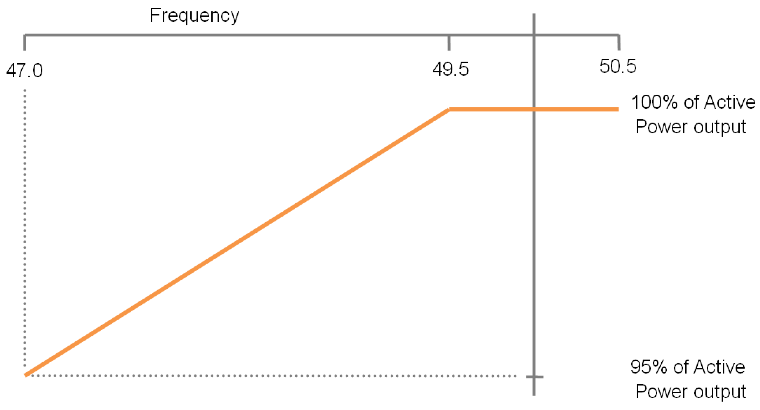
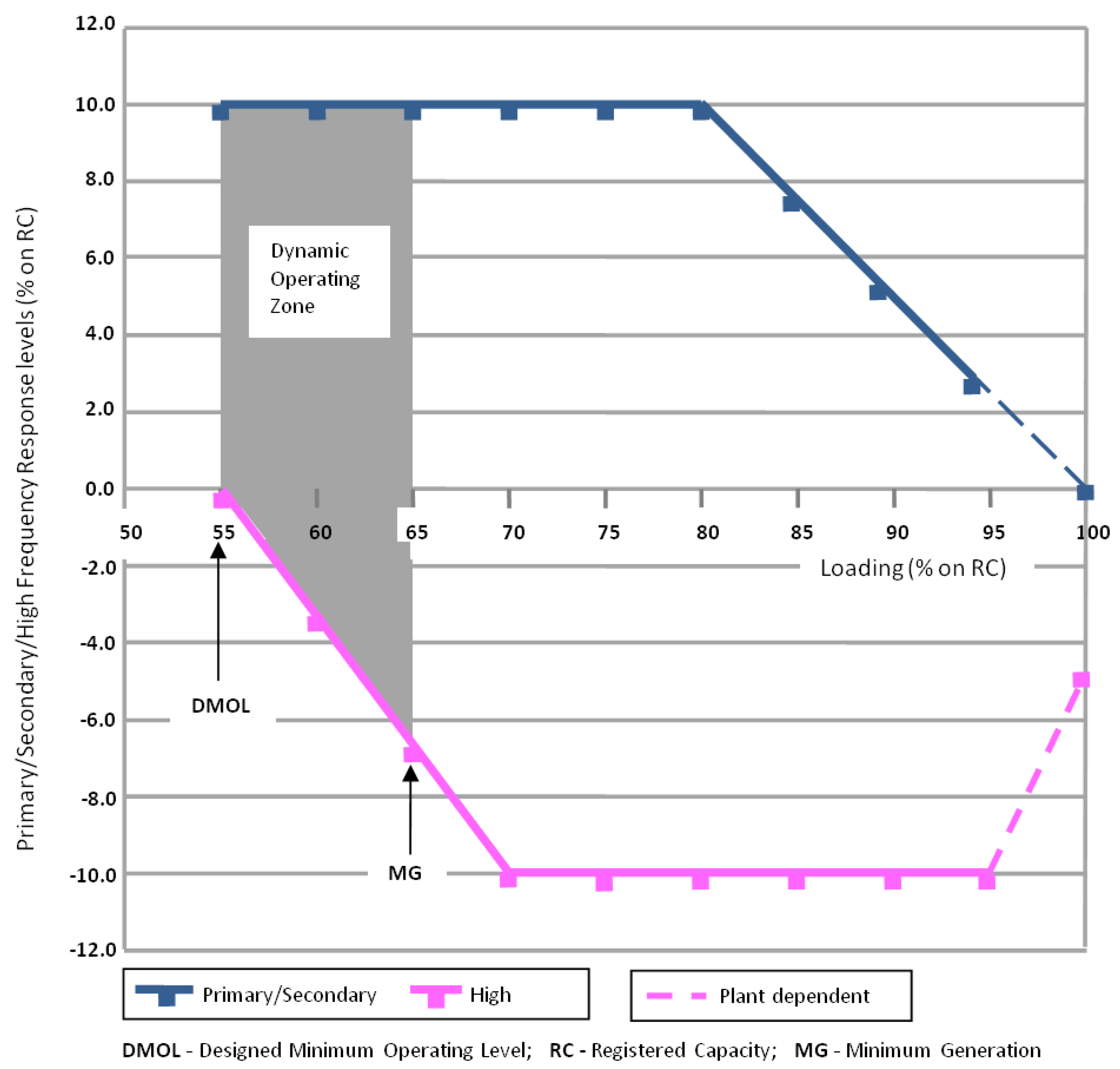
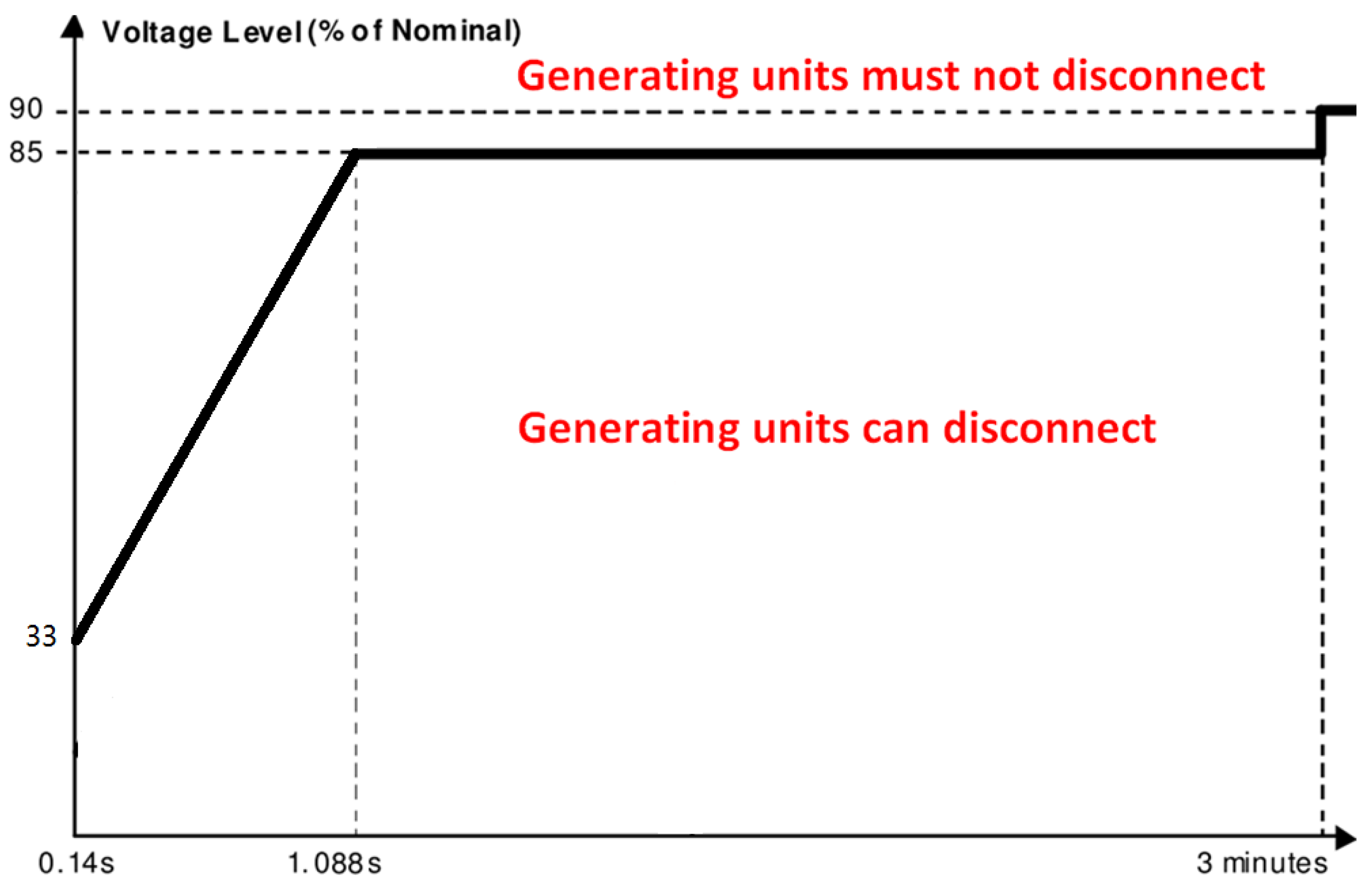
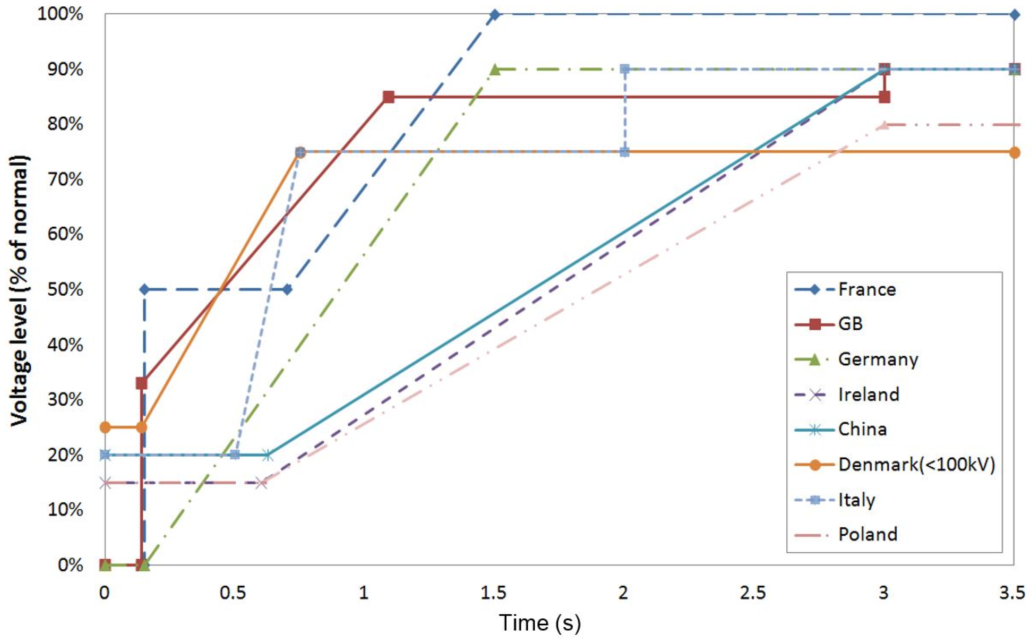
  • Technology breakthrough to different types of EES technologies is necessary. To provide services in relation to Grid Codes, the EES performance for meeting or evaluating the grid specifications on the active power output (e.g., Figure 1), the minimum frequency response (e.g., Figure 2), the FRT/LVRT characteristics (e.g., Figure 3 and Figure 6) and other requirements need further study, improve and optimize. In addition, from the view of energy/power saving with EES propagation in the grids, the cycle efficiencies of EES technologies especially to CAES, TES, fuel cells and liquid air storage must be improved. One approach is the intelligent concept (or system) design, such as adiabatic CAES, i.e., the integration of CAES and TES (the cycle efficiency can be improved from 42% to ~70%, [2,4]); another way is to develop the innovative efficient energy conversion components or to improve the existing energy conversion units in the concerned EES systems.

5. Conclusions

The paper provides a comprehensive overview of the different countries’ Grid Codes for EES grid connection and relevant applications, mainly on the voltage levels, the normal and critical frequency intervals, the outputs of generating units with the frequency variation, the frequency response (control) strategies, the FRT/LVRT characteristics and the recent updates relevant to EES. This leads to several tables and figures showing a detailed comparison of the Grid Codes’ corresponding specifications which show the technical requirements with the boundaries and how the EES systems can be allowed to be connected to the current grids. Then, with the presented key technical characteristics of different EES technologies, the potentials of EES options to implement the concerned applications for achieving or supporting the Grid Code realization are evaluated. The up-to-date academic R&D and the industrial commercialized facilities or demonstrations in the relevant areas are reviewed. Based on the above study, the technology development recommendations to EES technologies for the purpose of the Grid Codes’ realization and for implementing the corresponding applications are presented.
The overview has shown a synthesis of the EES promotion in relation to the Grid Code realization and evolution, which can be used for supporting the R&D in this area and for assessing EES technologies for relevant deployment. Although a number of demonstration projects or EES trial stations were completed and some of them connected to the grids, the corresponding detailed specifications in the Grid Codes are still not published in many countries. With treating the EES discharging as electricity generating units, the voltage and frequency regulations with controls are the main concerns in the Grid Code requirements in this paper. In addition, with the recent update, the modification is being considered in some Grid Codes for defining the specific technical requirements for EES systems connecting to the power systems, which can involve all sections of the Grid Code. The widespread deployment of EES in the power grids will drive the TSOs to make the real progress on the Grid Code upgrade. From the overview study, the hybrid EES development, integrating EES into the existing electricity generation, the software development for dynamic modelling of EES processes and the technology breakthrough with the maturity improvement to different EES technologies are considered as the major recommendations which can speed up the EES applications in the concerned fields.

Author Contributions

Xing Luo and Jihong Wang conceived and wrote the paper. Jacek D. Wojcik, Jianguo Wang, Decai Li, Mihai Draganescu, Yaowang Li and Shihong Miao contributed to the data selection, the literature work, the comprehensive analysis and the paper writing.

Acknowledgments

The authors would like to thank the funding support from Engineering and Physical Sciences Research Council (EPSRC) UK (EP/L019469/1, EP/K002228/1). In addition, the authors give their thanks to the support from China National Key Research and Development Program (2017YFB0903601) and China National Basic Research Program 973 (2015CB251301) for enabling the continuing collaborative research between the British and Chinese researchers.

Conflicts of Interest

The authors declare no conflict of interest.

References

  1. The Office of Gas and Electricity Markets (Ofgem), UK Government. Available online: https://www.ofgem.gov.uk/licences-industry-codes-and-standards/industry-codes/electricity-codes/grid-code (accessed on 19 April 2018).
  2. Luo, X.; Wang, J.; Dooner, M.; Clarke, J. Overview of current development in electrical energy storage technologies and the application potential in power system operation. Appl. Energy 2015, 137, 511–536. [Google Scholar] [CrossRef]
  3. Robyns, B.; Saudemont, C.; Hissel, D.; Roboam, X.; Sareni, B.; Pouget, J. Electrical Energy Storage in Transportation Systems; Electrical Engineering Series; Wiley Publishing: Hoboken, NJ, USA, 2016. [Google Scholar]
  4. Amirante, R.; Cassone, E.; Distaso, E.; Tamburrano, P. Overview on recent developments in energy storage: Mechanical, electrochemical and hydrogen technologies. Energy Convers. Manag. 2017, 132, 372–387. [Google Scholar] [CrossRef]
  5. Gopstein, A.M. Energy Storage & the Grid—From Characteristics to Impact [Point of View]. Proc. IEEE 2012, 100, 311–316. [Google Scholar] [CrossRef]
  6. Whittingham, M.S. History, Evolution, and Future Status of Energy Storage. Proc. IEEE 2012, 100, 1518–1534. [Google Scholar] [CrossRef]
  7. Etxegarai, A.; Eguia, P.; Torres, E.; Buigues, G.; Iturregi, A. Current procedures and practices on grid code compliance verification of renewable power generation. Renew. Sustain. Energy Rev. 2017, 71, 191–202. [Google Scholar] [CrossRef]
  8. Etxegarai, A.; Eguia, P.; Torres, E.; Iturregi, A.; Valverde, V. Review of grid connection requirements for generation assets in weak power grids. Renew. Sustain. Energy Rev. 2015, 41, 1501–1514. [Google Scholar] [CrossRef]
  9. Al-Shetwi, A.Q.; Sujod, M.Z.; Ramli, N.L. A review of the fault ride through requirements in different Grid Codes concerning penetration of PV system to the electric power network. ARPN J. Eng. Appl. Sci. 2015, 10, 9906–9912. [Google Scholar]
  10. Transmission System Operator for UK, Grid Code, Issue 5, Revision 21, UK Nationalgrid. 2017. Available online: http://www2.nationalgrid.com/UK/Industry-information/Electricity-codes/Grid-code/The-Grid-code/ (accessed on 19 April 2018).
  11. Christiansen, W.; Johnsen, D.T. Analysis of Requirements in Selected Grid Codes. Technical Report. 2006. Available online: http://0-bibing.us.es.fama.us.es/proyectos/abreproy/70370/fichero/24.+Analysis+of+the+requirements+in+selected+Grid+Codes.pdf (accessed on 19 November 2017).
  12. Rajský, F.; Donsión, M.P. Comparison of transmission and distribution systems in the Czech Republic and Spain. In Proceedings of the International Conference on Renewable Energies and Power Quality, Santander, UK, 12–14 March 2008; Volume 1, pp. 485–492. [Google Scholar]
  13. National Development and Reform Commission, the Grid Operation Code DL/T 1040, China. 2007. Available online: http://www.doc88.com/p-6911574628424.html (accessed on 16 December 2017).
  14. Rated Voltage Levels of China National Grid, EEPW Website. 8 December 2016. Available online: http://www.eepw.com.cn/article/201612/341323.htm (accessed on 16 February 2018).
  15. Electricity Transmission, Australian Energy Regulator Published, Australian Government Website. Available online: https://www.aer.gov.au/system/files/Chapter%205%20%20Electricity%20transmission%202009.pdf (accessed on 16 February 2018).
  16. A Dictionary on Electricity, Project Report, a Joint Project of CIGRE and AHEF, Electricity in Australia. Available online: http://www.ewh.ieee.org/r10/nsw/subpages/history/electricity_in_australia.pdf (accessed on 18 February 2018).
  17. Austrian Power Grid, Transmission System Operator for Austria. Available online: http://www.apg.at (accessed on 22 February 2018).
  18. Technische und Organisatorische Regeln Für Betreiber und Benutzer von Netzen, Hauptabschnitt D4: Parallelbetrieb von Erzeugungsanlagen mit Verteilernetzen, E-control, Ver 2.1. 2013. Available online: https://www.e-control.at/documents/20903/26585/TOR_D4_V2_1_040913.pdf/1908f104-70d8-4511-b2ce-2e10ac3e9e50 (accessed on 26 February 2018).
  19. Compania Naţională de Transport al Energiei Electrice Transelectrica S.A. Codul Tehnical Retelei Electrice de Transport, Aprobat Prin Ordinul ANRE nr. 2004. Available online: http://www.transelectrica.ro/documents/10179/33158/cod_ret_ro.pdf/5cf5bb39-2efb-48f7-9ebc-491dfdb7d6e0 (accessed on 2 March 2018).
  20. E.ON Netz GmbH, Annexe EON HV Grid Connection Requirements. Technical Report. 2006. Available online: http://www.pvupscale.org/spip.php?article13 (accessed on 7 May 2017).
  21. Hirst, E. U.S. Transmission Capacity: Present Status and Future Prospects. Technical Report; 2004. Available online: https://www.energy.gov/sites/prod/files/oeprod/DocumentsandMedia/transmission_capacity.pdf (accessed on 7 May 2017).
  22. Edison Electric Institute (EEI). State Generation & Transmission Siting Directory. 2013. Available online: http://www.pvupscale.org/IMG/pdf/D4_2_DE_annex_A-3_EON_HV_grid_connection_requirements_ENENARHS2006de.pdf (accessed on 8 May 2017).
  23. EirGrid, EirGrid Grid Code Version 6.0. 2015. Available online: http://www.eirgridgroup.com/site-files/library/EirGrid/GridCodeVersion6.pdf (accessed on 9 May 2017).
  24. Documentation Technique de Reference, RTE—Transmission System Operator for France. 2012. Available online: http://clients.rte-france.com/htm/fr/mediatheque/telecharge/reftech/03-05-13_complet.pdf (accessed on 9 October 2017).
  25. Andersen, F.M.; Jensen, S.G.; Larsen, H.V.; Meibom, P.; Ravn, H.; Skytte, K.; Togeby, M. Analysis of Demand Response in Denmark. Risø National Laboratory, 2006. Available online: http://www.ea-energianalyse.dk/reports/511_Analyses_of_Demand_Response_in_Denmark.pdf (accessed on 15 August 2017).
  26. Walloon Energy Commission. Grid Code for the Local Transmission System Operator; Walloon Energy Commission: Wallonia, Belgium, 2007. [Google Scholar]
  27. Cronin, T. An overview of grid requirements in Denmark and the DTU advanced grid test facility in Osterid. In Proceedings of the 1st International Workshop on Grid Simulator Testing of Wind Turbine Drivetrains, Boulder, CO, USA, 13–14 June 2013. [Google Scholar]
  28. Berndt, H.; Hermann, M.; Kreye, H.D.; Reinisch, R.; Scherer, U.; Vanzetta, J. TransmissionCode 2007: Network and System Rules of the German Transmission System Operators. 2007. Available online: https://www.bdew.de/internet.nsf/id/A2A0475F2FAE8F44C12578300047C92F/$file/TransmissionCode.pdf (accessed on 15 April 2017).
  29. Nordic Grid Code 2007—Nordic Collection of Rules. 2007. Available online: https://www.entsoe.eu/fileadmin/user_upload/_library/publications/nordic/planning/070115_entsoe_nordic_NordicGridCode.pdf (accessed on 16 May 2017).
  30. Energinet, the Danish Ministry of Energy, Utilities and Climate, Technical Regulation for Thermal Power Station Units of 1.5 MW and Higher: Regulation for Grid Connection TF 3.2.3, Version 5.1. 2008. Available online: http://www.energinet.dk/EN/Soeg/Sider/resultsNew.aspx?k=grid%20code (accessed on 16 May 2017).
  31. Published Regulation Network Codes, Commission Regulation (EU) 2016/631. Available online: https://electricity.network-codes.eu/network_codes/rfg/ (accessed on 5 April 2018).
  32. Hirth, L.; Ziegenhagen, I. Control Power and Variable Renewables: A Glimpse at German Data; Fondazione Eni Enrico Mattei Milano: Milano, Italy, 2013. [Google Scholar]
  33. Arias, I.M.I. Grid Codes Comparison. Master’s Thesis, Chalmers University of Technology, Göteborg, Sweden, 2006. [Google Scholar]
  34. Merino, J.; Mendoza-Araya, P.; Veganzones, C. State of the Art and Future Trends in Grid Codes Applicable to Isolated Electrical Systems. Energies 2014, 7, 7936–7954. [Google Scholar] [CrossRef]
  35. UK National Grid, GC0096: Energy Storage, Documents, Proposal and Workgroup. 12 January 2018. Available online: https://www.nationalgrid.com/uk/electricity/codes/grid-code/modifications/gc0096-energy-storage (accessed on 16 March 2018).
  36. Establishing a Network Code on Requirements for Grid Connection of Generators, Official Journal of the European Union, L112/1. 27 April 2016. Available online: https://eur-lex.europa.eu/legal-content/EN/TXT/?uri=CELEX%3A32016R0631 (accessed on 14 January 2018).
  37. EPRI-DOE. Handbook of Energy Storage for Transmission and Distribution Applications; EPRI-DOE: Palo Alto, CA, USA; Washington, DC, USA, 2003.
  38. Highview Power Storage: Secure, Clean Power. Highview Power. 2011. Available online: http://www.imeche.org/docs/default-source/2011-press-releases/Highview_2pager.pdf?sfvrsn=0 (accessed on 16 February 2017).
  39. Lawder, M.T.; Suthar, B.; Northrop, P.W.C.; De, S.; Hoff, C.M.; Leitermann, O.; Crow, M.L.; Santhanagopalan, S.; Subramanian, V.R. Battery Energy Storage System (BESS) and Battery Management System (BMS) for Grid-Scale Applications. Proc. IEEE 2014, 102, 1014–1030. [Google Scholar] [CrossRef]
  40. Renewable Energy Association. Energy Storage in the UK: An Overview. 2015. Available online: https://www.r-e-a.net/upload/rea_uk_energy_storage_report_november_2015_-_final.pdf (accessed on 28 December 2016).
  41. Pan, F.; Wang, Q. Redox Species of Redox Flow Batteries: A Review. Molecules 2015, 20, 20499–20517. [Google Scholar] [CrossRef] [PubMed]
  42. US Department of Energy Global Energy Storage Database. EFDA JET Fusion Flywheel. Available online: https://www.energystorageexchange.org/projects/852 (accessed on 26 September 2017).
  43. Sodium-Nickel-Chloride Battery, European Association for Storage of Energy. 2016. Available online: http://ease-storage.eu/wp-content/uploads/2016/07/EASE_TD_Electrochemical_NaNiCl2.pdf (accessed on 2 April 2018).
  44. Bignucolo, F.; Caldon, R.; Coppo, M.; Pasut, F.; Pettinà, M. Integration of Lithium-Ion Battery Storage Systems in Hydroelectric Plants for Supplying Primary Control Reserve. Energies 2017, 10, 98. [Google Scholar] [CrossRef]
  45. Budt, M.; Wolf, D.; Span, R.; Yan, J. A review on compressed air energy storage: Basic principles, past milestones and recent developments. Appl. Energy 2016, 170, 250–268. [Google Scholar] [CrossRef]
  46. Energy Storage Association. Frequency Regulation: Executive Summary & Discussion. Available online: http://energystorage.org/energy-storage/technology-applications/frequency-regulation (accessed on 26 April 2017).
  47. E.ON Netz GmbH. Grid Code—High and Extra High Voltage. April 2006. Available online: http://www.pvupscale.org/IMG/pdf/D4_2_DE_annex_A-3_EON_HV_grid_connection_requirements_ENENARHS2006de.pdf (accessed on 28 July 2016).
  48. Raju, M.; Khaitan, S.K. Modeling and simulation of compressed air storage in caverns: A case study of the Huntorf plant. Appl. Energy 2012, 89, 474–481. [Google Scholar] [CrossRef]
  49. Enhanced Frequency Response (EFR), UK National Grid. Available online: https://www.nationalgrid.com/uk/electricity/balancing-services/frequency-response-services/enhanced-frequency-response-efr (accessed on 8 April 2018).
  50. What is Enhanced Frequency Response and Which Are Its Benefits? Logicenergy Company. Available online: https://www.logicenergy.com/what-is-enhanced-frequency-response-and-which-are-its-benefits/ (accessed on 8 April 2018).
  51. Pratt, D. Battery Storage Dominates National Grid EFR Tender Results, Energy Storage News, Solar Media Limited. 26 August 2016. Available online: https://www.energy-storage.news/news/battery-storage-dominates-national-grid-efr-tender-results (accessed on 5 April 2018).
  52. Cho, Y.; Shim, J.W.; Kim, S.J.; Min, S.W.; Hur, K. Enhanced frequency regulation service using Hybrid Energy Storage System against increasing power-load variability. In Proceedings of the 2013 IEEE Power & Energy Society General Meeting, Vancouver, BC, Canada, 21–25 July 2013; pp. 1–5. [Google Scholar]
  53. Wojcik, J.; Wang, J. Technical feasibility study of thermal energy storage integration into the conventional power plant cycle. Energies 2017, 10, 205. [Google Scholar] [CrossRef]
  54. Li, D.; Hu, Y.; He, W.; Wang, J. Dynamic modelling and simulation of a combined-cycle power plant integration with thermal energy storage. In Proceedings of the 23rd International Conference on Automation & Computing, Huddersfield, UK, 7–8 September 2017. [Google Scholar]
  55. Vaca, S.M.; Patsios, C.; Taylor, P. Enhancing frequency response of wind farms using hybrid energy storage systems. In Proceedings of the 2016 IEEE International Conference on Renewable Energy Research and Applications (ICRERA), Paris, France, 14–17 October 2016; pp. 325–329. [Google Scholar]
  56. Ammar, M.; Joos, G. A short-term energy storage system for voltage quality improvement in distributed wind power. IEEE Trans. Energy Convers. 2014, 29, 997–1007. [Google Scholar] [CrossRef]
  57. Guo, W.; Xiao, L.; Dai, S. Enhancing Low-Voltage Ride-Through Capability and Smoothing Output Power of DFIG with a Superconducting Fault-Current Limiter–Magnetic Energy Storage System. IEEE Trans. Energy Convers. 2012, 27, 277–295. [Google Scholar] [CrossRef]
  58. Serban, E.; Ordonez, M.; Pondiche, C. Voltage and Frequency Grid Support Strategies Beyond Standards. IEEE Trans. Power Electron. 2017, 32, 298–309. [Google Scholar] [CrossRef]
  59. Bignucolo, F.; Cerretti, A.; Coppo, M.; Savio, A.; Turri, R. Effects of Energy Storage Systems Grid Code Requirements on Interface Protection Performances in Low Voltage Networks. Energies 2017, 10, 387. [Google Scholar] [CrossRef]
  60. Le, H.T.; Santoso, S. Operating compressed-air energy storage as dynamic reactive compensator for stabilising wind farms under grid fault conditions. IET Renew. Power Gener. 2013, 7, 717–726. [Google Scholar] [CrossRef]
  61. Bignucolo, F.; Lorenzoni, A. Transmission and distribution networks regulation through dedicated cableway plants. In Proceedings of the IEEE AEIT Annual Conference—From Research to Industry: The Need for a More Effective Technology Transfer, Trieste, Italy, 18–19 September 2014; pp. 1–6. [Google Scholar]
  62. Bignucolo, F.; Savio, A.; Raciti, A. Cableway Storage System regulation to supply ancillary services to the distribution and transmission network. In Proceedings of the IEEE 50th International Universities Power Engineering Conference (UPEC), Stoke on Trent, UK, 1–4 September 2015; pp. 1–6. [Google Scholar]
  63. Bignucolo, F.; Cerretti, A.; Coppo, M.; Savio, A.; Turri, R. Impact of Distributed Generation Grid Code Requirements on Islanding Detection in LV Networks. Energies 2017, 10, 156. [Google Scholar] [CrossRef]
  64. Energy Storage Association. Variable Speed Pumped Hydroelectric Storage. Available online: http://energystorage.org/energy-storage/technologies/variable-speed-pumped-hydroelectric-storage (accessed on 16 August 2017).
  65. Toshiba Corporation. Adjustable Speed Pumped Storage. Available online: http://www.toshiba.co.jp/thermal-hydro/en/hydro/products/pump/storage.htm (accessed on 18 July 2017).
  66. Smart Storage Pty Ltd. (Trading as Ecoult). White Paper—Public-Domain Test Data Showing Key Benefits and Applications of the UltraBattery. January 2014. Available online: http://www.ecoult.com/images/files/whitepapers/Ecoult_UltraBattery_White_Paper_General_Version.pdf (accessed on 23 August 2017).
  67. Altair Nanotechnologies Inc. Advanced Energy Storage Systems for Frequency Regulation. White Paper. Available online: http://en.escn.com.cn/Tools/download.ashx?id=130 (accessed on 12 June 2016).
  68. Spahic, E.; Pieschel, M.; Alvarez, R.; Kuhn, G.; Hild, V.; Beck, G.; Platt, N. Power Intensive Energy Storage and Multilevel STATCOM for Frequency and Voltage Grid Support, the Proceedings of CIGRE Session 2016. Available online: http://www.ptd.siemens.de/C4-110_CIGRE2016_SVCPLUSFS_final.pdf (accessed on 12 September 2017).
  69. Ecoult Energy Storage Solutions, Case Study: PJM Interconnection (PA, US) Regulation Services. Available online: http://www.ecoult.com/component/phocadownload/category/3-case-studies?download=3:ecoult-case-study_regulation-services_pjm-interconnection_pa_usa (accessed on 12 September 2017).
  70. Ecoult Energy Storage Solutions, Ecoult Megawatt Scale Energy Storage. Available online: https://www.parliament.nsw.gov.au/committees/DBAssets/InquiryOther/Transcript/8056/CSIRO%20attachment%201a%20-%20Hampton.PDF (accessed on 18 September 2017).
  71. Highview Power Storage. Pre-Commercial LAES Technology Demonstrator: Transforming Waste. Available online: http://www.highview-power.com/pre-commercial-laes-technology-demonstrator/ (accessed on 25 September 2017).
  72. US Department of Energy Global Energy Storage Database. Pre-Commercial Liquid Air Energy Storage Technology Demonstrator. Available online: https://www.energystorageexchange.org/projects/2163 (accessed on 25 September 2017).
  73. ABB Group. ABB Commissions Dynamic Energy Storage Installation in the UK. Available online: http://www.abb.com/cawp/seitp202/31c5b55bad616492c1257895002628e1.aspx (accessed on 26 September 2017).
  74. EUROfusion. JET Flywheels: Research for Tomorrow’s Energy Supply. Available online: https://www.euro-fusion.org/fusion/jet-tech/jets-flywheels/ (accessed on 26 April 2017).
  75. US Department of Energy Global Energy Storage Database. Available online: https://www.energystorageexchange.org/projects/ (accessed on 17 June 2017).
  76. The Electrical Energy Storage Magazine (EES International). Energy Storage in China. 2014. Available online: http://www.ees-magazine.com/energy-storage-in-china/ (accessed on 15 March 2017).
  77. Advanced Rail Energy Storage, ARES Nevada, Ares North America. Available online: https://s3.amazonaws.com/siteninja/multitenant/assets/21125/files/original/All_About_ARES_-_070616.pdf (accessed on 18 March 2018).
  78. Railway Solution for Grid-Scale Energy Storage, Ares North America. 12 May 2016. Available online: https://www.aresnorthamerica.com/article/8957-railway-solution-for-grid-scale-energy-storage (accessed on 18 March 2018).
Figure 1. Comparison of the range of normal operation frequency variation and the range of critical frequency variations in different countries [1,10,11,13,15,17,18,19,20,21,22,23,24,25,26].
Energies 11 01070 g001
Figure 2. The requirement of the active power output from GB grid-connected generating units with the frequency change within the range of 47.0–50.5 Hz [10].
Energies 11 01070 g002
Figure 3. The minimum frequency response requirement profile for a 0.5 Hz frequency changing in the GB grid from target frequency [10].
Energies 11 01070 g003
Figure 4. The requirements of FRT/LVRT to synchronous generating units in UK Supergrid (above 200 kV) to the voltage dip on the onshore transmission system duration greater than 140 ms [10].
Energies 11 01070 g004
Figure 5. Comparison of the requirements of generating units with frequency variations in different countries [10,13,19,24,28,29,30,31].
Energies 11 01070 g005
Figure 6. The German Grid Code requirements of generating units as a function of the grid frequency and voltage [28].
Energies 11 01070 g006
Figure 7. Comparison of the requirements of FRT/LVRT in Grid Codes [7,9,10,11,12,13,14,20,21,22,23,24,31,33,34].
Energies 11 01070 g007
Table 1. Normal operating voltage ranges of the UK national electricity transmission system [1,10].
UK National Electricity Transmission Rated VoltageAllowed Operating Range 1
400 kV400 kV ± 5%
275 kV275 kV ± 10%
132 kV132 kV ± 10%
Below 132 kV±6%
1 User(s) may agree to more or less variations compared with Table 1 to a particular connection site.
Table 2. Rated operating voltage levels in different countries [1,3,10,11,12,13,14,15,16,17].
Country NamesAllowed Operating Voltages
Great Britain400, 275, 132 kV and below
Germany380, 220 and 110 kV; 155 kV for offshore grid-connection
Ireland400, 220 and 110 kV
FranceExtra High Voltage (400, 225 and 150 kV) and High Voltage (90 and 63 kV)
Italy380, 220 and 150 kV
Belgium70–30 and 380–150 kV
Denmark400, 220, 150 and 132 kV
Austria380, 220 and 110 kV
Romania750, 400 and 220 kV
Poland750, 400, 220 and 110 kV
Australia500, 330, 275, 220, 132 and 66 kV
ChinaExtra High Voltage (1000, 750, 500 and 330 kV), High Voltage (220, 110 and 66 kV)
Table 3. Normal operation frequency variation intervals [1,11,13,14,15,16,17,18,19,20,21].
CountryFrequency IntervalCountryFrequency Interval
Great Britain49.5–50.5 HzIreland49.8–50.2 Hz
Germany49.5–50.5 HzItaly49.9–50.1 Hz
France49.5–50.5 HzPoland49.5–50.5 Hz
Belgium49.5–50.5 HzDenmark49.9–50.1 Hz
Austria49.5–50.5 HzRomania49.5–50.5 Hz
Australia49.75–50.25 HzChina49.8–50.2 Hz
Table 4. Critical frequency variation intervals [1,10,11,13,15,17,18,19,20,21,22,23,24,25,26].
CountryCritical Frequency IntervalCountryFrequency Interval
Great Britain47.0–52.0 HzIreland47.0–52.0 Hz
Germany47.0–52.0 HzItaly47.5–51.5 Hz
France47.0–52.0 HzPoland47.0–52.0 Hz
Belgium47.0–52.0 HzDenmark47.5–51.0 Hz
Austria47.5–51.5 HzRomania47.0–52.0 Hz
Australia47.0–52.0/55.0 HzChina48.0–51.0 Hz
Table 5. The requirements of generating units regarding the GB grid frequency variations [10].
Frequency RangesRequirements
51.5–52.0 HzOperation for a period at least 15 min is required for each time the frequency in this range.
51.0–51.5 HzOperation for a period at least 90 min is required for each time the frequency in this range.
49.0–51.0 HzContinuous operation is required.
47.5–49.0 HzOperation for a period at least 90 min is required for each time the frequency in this range.
47.0–47.5 HzOperation for a period at least 20 s is required for each time the frequency in this range.
Table 6. The frequency response of generating units specified in the GB Grid Code [1,10].
Type of Frequency ResponseInformation
Primary (Frequency) ResponseThe minimum increase in the unit’s active power output provided within the duration of 10–30 s after the time of the start of the frequency fall (Figure CC.A.3.2 in [10])
Secondary (Frequency) ResponseThe minimum increase in the generating unit’s active power output provided within the duration of 30 s to 30 min after the start of frequency fall (Figure CC.A.3.2 in [10])
High Frequency ResponseThe reduction in the generating unit’s active power output in response to an increase in system frequency above the target frequency; it must provide within 10 s after the start of the frequency increase and must be maintained thereafter
Table 7. Comparison of frequency control strategies [10,13,24,28,29,30,32].
CountryType of Relevant StrategyResponse Time Relevant Information
GBPrimary (Frequency) Responsesee Table 6
Secondary (Frequency) Response
High Frequency Response
IrelandPrimary Frequency ControlTaking place up to 30 s after a change in frequency and achieved by automatic corrective responses to frequency deviations
Secondary Frequency ControlTaking place from 5 s up to 10 min after the change in frequency and provided by a combination of automatic and manual actions
Operating ReservePrimary Operating ReserveActivate at the frequency minimum which occurs between 5 s and 15 s after an event
Secondary Operating ReserveAvailable after 15 s from the start of the frequency fall and sustainable up to 90 s following an event
Tertiary Operating Reserve band 1Available and sustainable over the period from 90 s to 5 min following an event
Tertiary Operating Reserve band 2Available and sustainable over the period from 5 min to 20 min following an event
France, ItalyPrimary Control50% of active power increase within 15 s;
100% of active power increase within 30 s;
100% of active power increase supplied for at least 15 min
Secondary ControlActivate no later than 30 s after an event and its operation must end within 15 min
Tertiary ControlActivate during Secondary Control and maintain for no longer than 15 min
GermanyPrimary ControlThe generating unit be capable of activating 100% of active power within 30 s after an event and maintain supply for at least 15 min
Secondary ControlThe generating unit be capable of activating 100% of active power evenly within 5 min
Minutes ReserveThe minutes reserve power must provide within 15 min; the delivery shall be made at a lead time of at least 7 ½ minutes at the beginning of the following quarter hour
DenmarkPrimary ControlA frequency response of 18,000 MW/Hz is required
Control ReserveIf a rapid change of frequency to 49.9/50.1 Hz, the reserve shall be regulated within 2 to 3 min;
If a frequency drop to 49.5 Hz, 50 % of the frequency controlled reserve shall be regulated upwards within 5 s; 100% of the reserve shall be regulated within 30 s
ChinaPrimary Frequency ControlDelay time within 3 s and the active power fully increasing within 15 s
Secondary Frequency ControlThe active power normally increasing within 1 min
Table 8. Key technical characteristics of EES technologies for Grid Code realization [2,3,4,5,6,37,38,39,40,41,42,43,44].
TechnologyPower Rating (MW)Response TimeDischarge TimeCycle Efficiency (%)Rated Energy (MWh)Maturity
PHS30–5000 minutes1–24 h+70–87180–8000mature
Large-scale CAESup to 300 and more4–12 min1–24 h+42–54, could up to 70up to 2860commercialized A-CAES demo
Small-scale CAESup to 10–20seconds to minutes30 s–3 h60–70, discharge 80+0.002–0.0083early commercialized
Flywheel0.1–400 for multi units<1 cycle, up to secondsup to 15 min85–95up to 5 early commercialized
Lead-acidup to 40<1/4 cycle, millisecondsseconds–10 h63–80, possible to 900.0005–40commercialized-mature
Li-ionup to 50, maybe more<1/4 cycle, millisecondsminutes–hours75–97~0.004–10demonstration
NaSup to 50seconds–hours60–900.4–244.8commercialized
NiCdup to 40<1/4 cycle, millisecondsseconds–hours60–836.75 commercialized
Na-NiCl2Several MWmillisecondsseconds–hours75–95Possible up to several MWhdemo/early commercialized
VRB~0.03–3, possible 50<1/4 cycleseconds–24 h+65–85<60demo/early commercialized
ZnBr0.05–10<1/4 cycleseconds–10 h+65–800.1–4demonstration
PSBup to 1520 msseconds–10 h+60–75developing
Capacitorup to 0.05<1/4 cycle, millisecondsmilliseconds–1 h60–70+commercialized
Super-capacitorup to ~0.3<1/4 cycle, millisecondsmilliseconds–1 h84–970.0005developing-demonstration
SMES0.1–10 <1/4 cycle, millisecondsmilliseconds–30 min 95–98up to 0.015demo-early commercialized
Solar fuelcould up to 10, developing 201–24 h+30, possible up to ~50developing
Hydrogen Fuel cellup to ~60seconds to minutesseconds to 24 h+up to ~700.312, developing 39developing-demonstration
Thermal storageup to 300not for rapid response up to 24 h+ 30–60, could higherdemo-early commercialized
Liquid air Storage10–50, could up to 200minutes several hours 30–40, 55–80 (waste heat)2.5developing-demonstration
Table 9. EES options for providing frequency control to meet GB and Germany Grid Codes.
Type of Frequency Control (Response) StrategyGrid Code Specifications to Response Time and Duration [10,28,31,37]Available and Promising EES Options (the Maturity Getting the Demonstration Stage at Least) [2,4,37,40]
GB: Primary (Frequency) ResponseGB: the minimum increase in active power output within the duration of 10–30 s after the time of the start of frequency fallAvailable: Flywheels (up to seconds, up to ~20 MW/5 MWh);
Lead-acid, Li-ion, NaS and NiCd batteries (milliseconds, up to ~50 MW/40 MWh);
VRB and ZnBr flow batteries (milliseconds, up to ~50 MW/60 MWh);
SMES (milliseconds, short storage duration, up to 10 MW/0.015 MWh);
Promising: Hybrid EES (at least one fast response technology needs to be used in hybrid EES)
Germany: Primary ControlGermany: the generating unit be capable of activating 100% of active power within 30 s after an event and maintain supply for at least 15 min
GB: Secondary (Frequency) ResponseGB: the minimum increase in active power output within the duration of 30 s to 30 min after the time of start of frequency fallBesides the technologies listed for Primary (Frequency) Response/Control, the below technologies have potentials:
Fuel cells (seconds to minutes, up to ~60 MW)
Small-scale CAES
(seconds, up to 10–20 MW)
Germany: Secondary ControlGermany: the generating unit be capable of activating 100% of active power evenly within 5 min
GB: High Frequency ResponseGB: the minimum decrease in active power output within the duration of 10 s after the time of the start of the frequency increase and maintained thereafterAvailable EES options could be the same as the technology candidates which can provide Primary (Frequency) Response/Control. However, if the EES has two separate processes for charging and discharging, it requires a particular attention.
Germany: Minutes ReserveGermany: the minutes reserve power must provide within 15 min; the delivery shall be made at a lead time of at least 7 ½ minutes at the beginning of the following quarter hourBesides the technologies listed for Primary (Frequency) Response/Control, the below could provide this service if they working on their standby modes:
PHS (minutes, up to 5000 MW/8000 MWh);
CAES (minutes, ~300 MW/2860 MWh);
TES (minutes, up to 300 MWh)
Table 10. Analysis of EES options to some grid ancillary services [2,3,4,5,6,9,11,33,37,40,49].
Ancillary Service Application AreasApplication Characteristics and SpecificationsExperienced and Promising EES Technology Options
Low voltage ride-throughA few MW to 10 MW, response time (~milliseconds), discharge duration (~minutes)Flywheels, batteries, flow batteries, SMES, hybrid EES
Voltage regulation and controlUp to a few of MW, response time (milliseconds), discharge duration (up to minutes)Batteries, flow batteries, SMES, flywheels, hybrid EES
Grid fluctuation suppressionMW level, response time (milliseconds), duration (up to ~minutes) batteries, flywheels, flow batteries, SMES, hybrid EES
Enhanced frequency responseDelivering 1–50 MW of response within 1 s to frequency deviations, duration at rated power for at least 30 minbatteries, flywheels; possible flow batteries, SMES, hybrid EES
Spinning reserveMW level, response time (up to a few seconds), discharge duration (30 min to a few hours)Batteries, small-scale CAES, flywheels, flow batteries, SMES, fuel cells, hybrid EES
Load followingMW level (up to hundreds of MW), response time (up to ~1 s), duration (minutes to a few hours)batteries, flow batteries, SMES, fuel cells, hybrid EES

