Roof Strata Behavior and Support Resistance Determination for Ultra-Thick Longwall Top Coal Caving Panel: A Case Study of the Tashan Coal Mine

 ,
,
Abstract
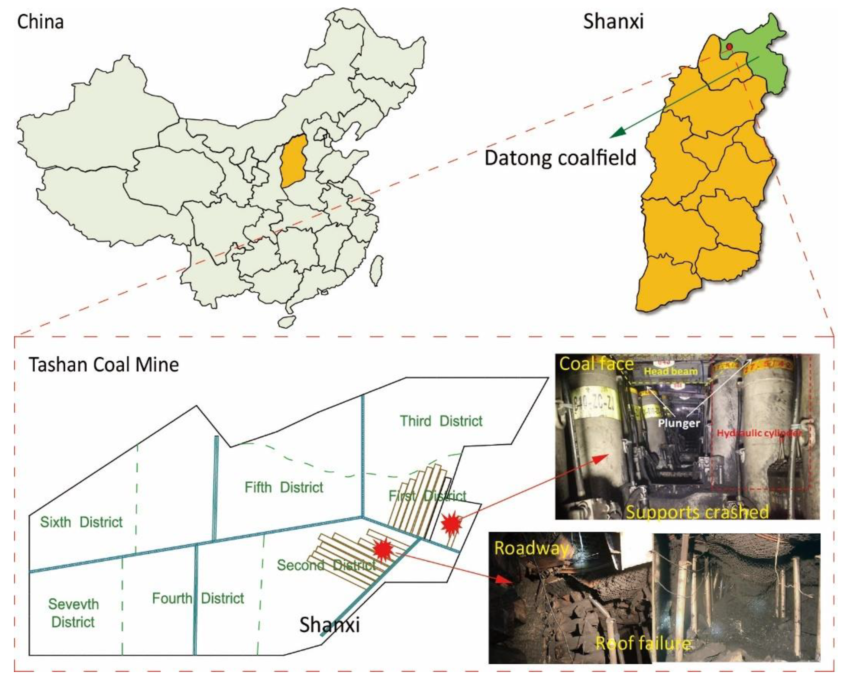
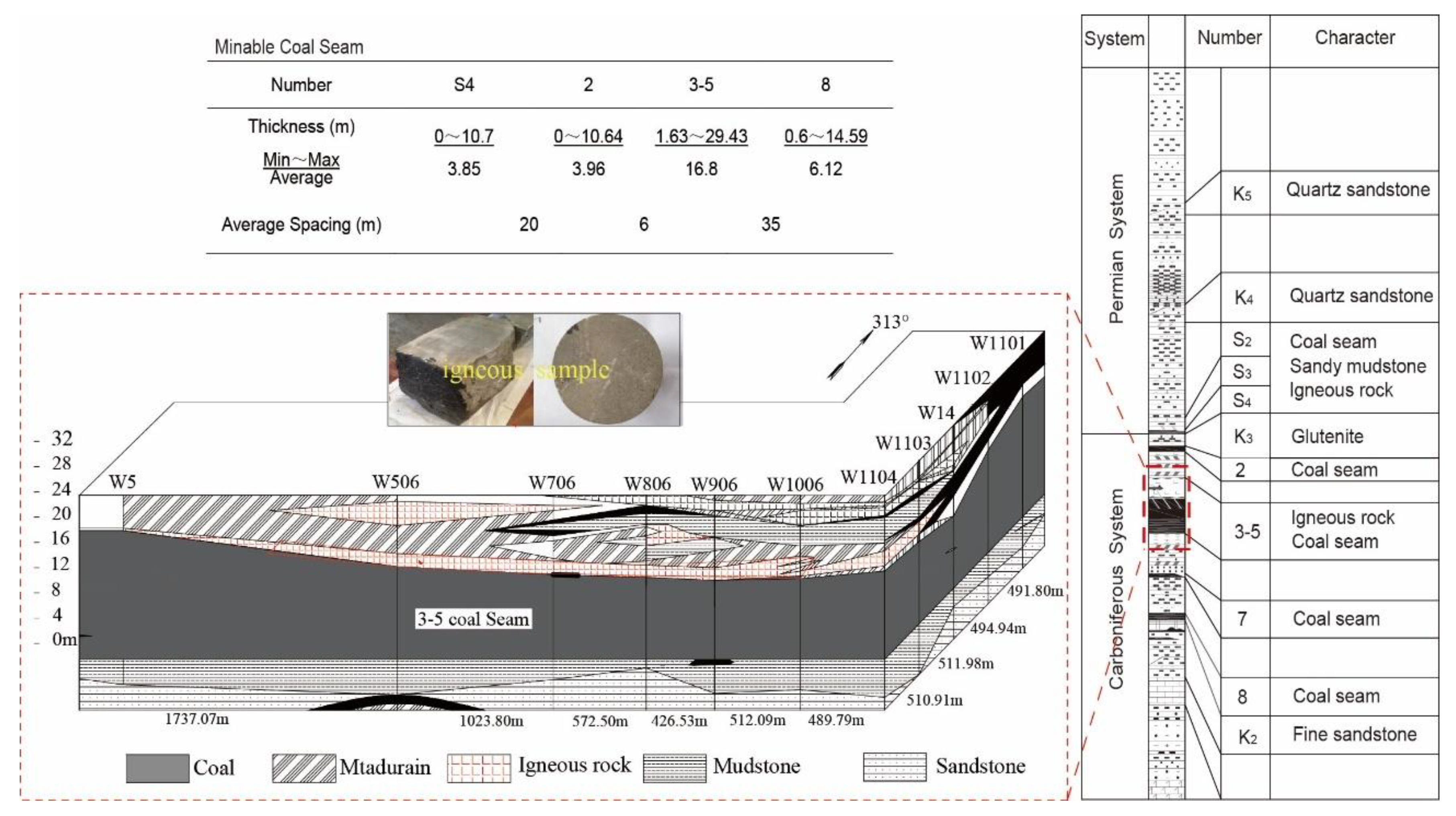
:1. Introduction
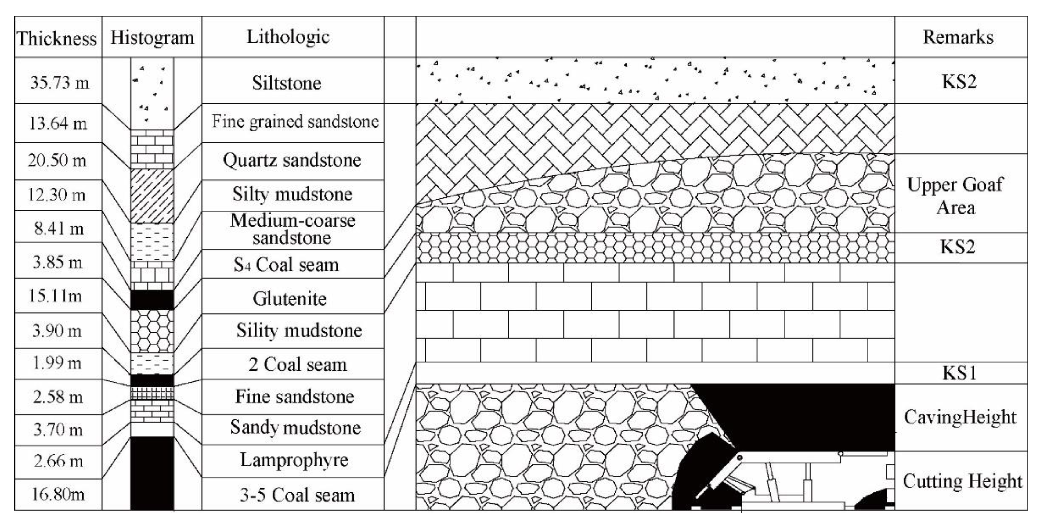
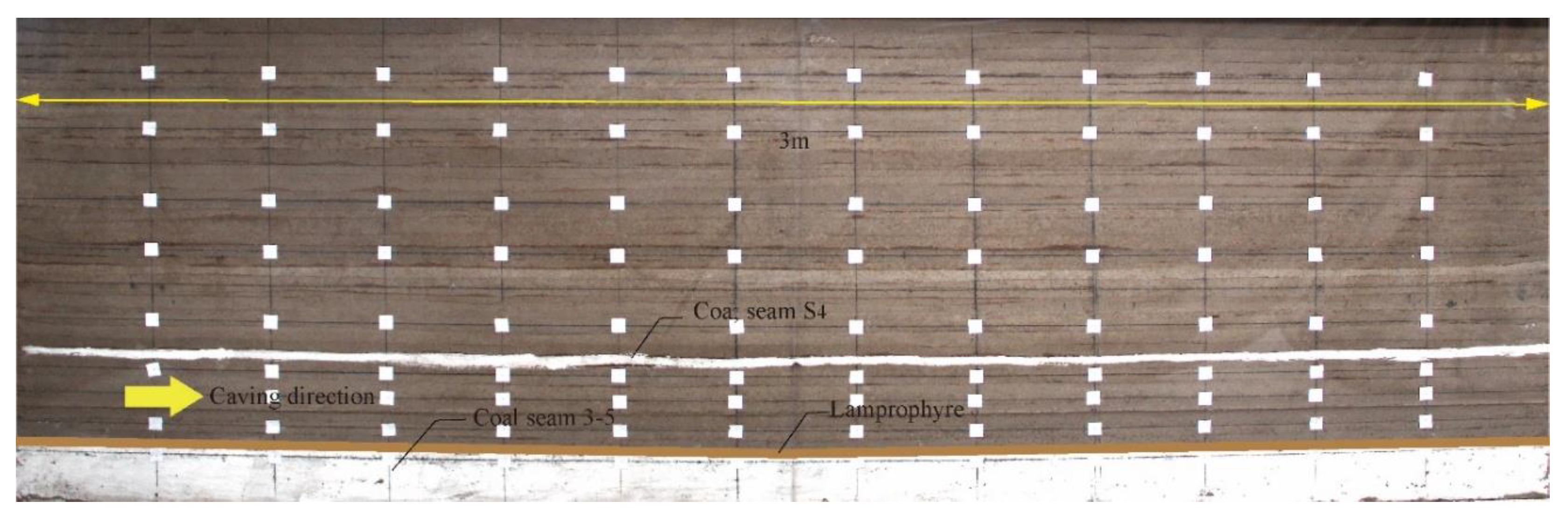
2. Physical Modeling
3. Modeling Results
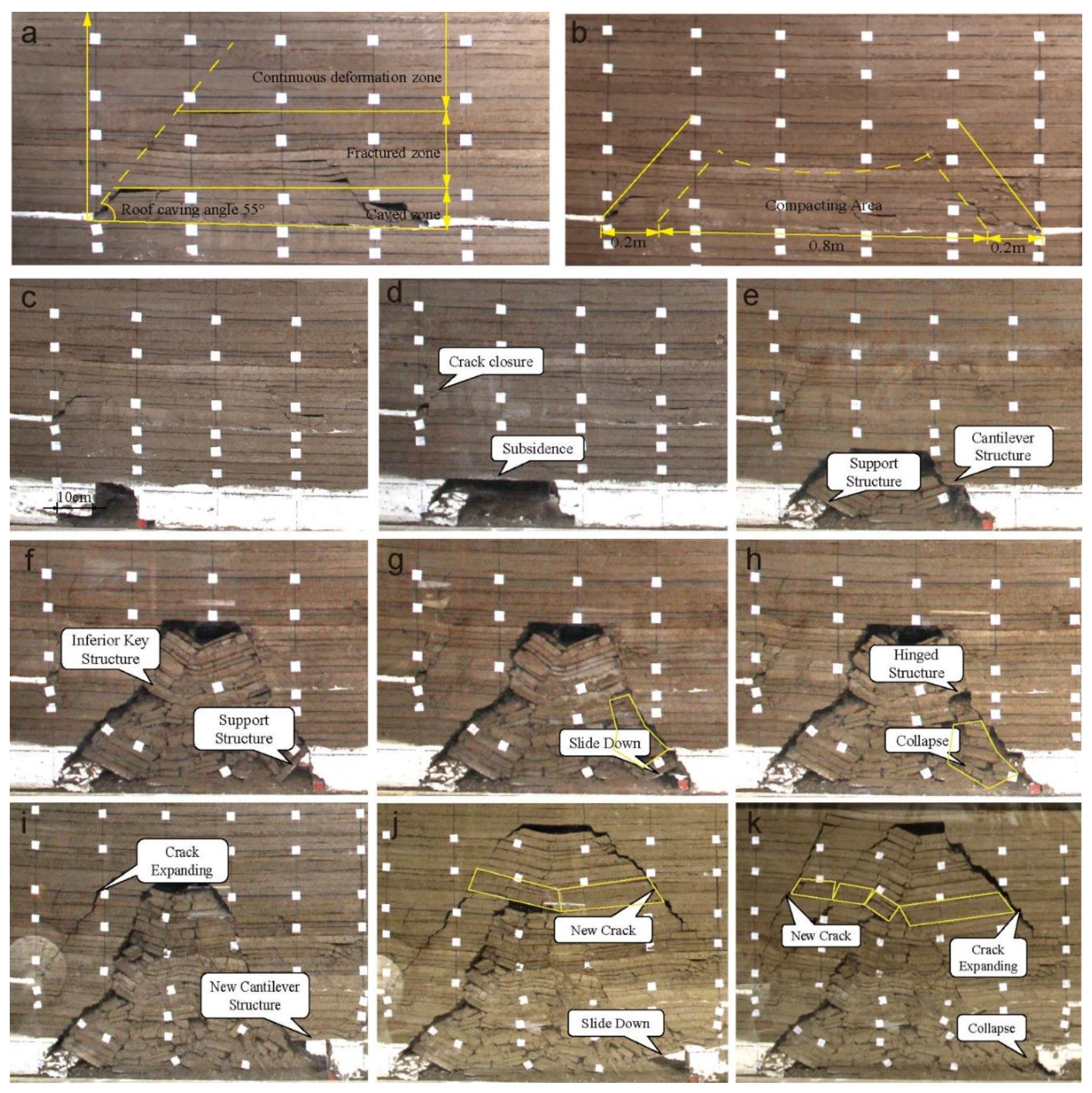
3.1. Structural Characteristics of the Strata on the Upper Gob
3.2. Structural Evolution of the Strata on the LTCC Panel
4. Discussion
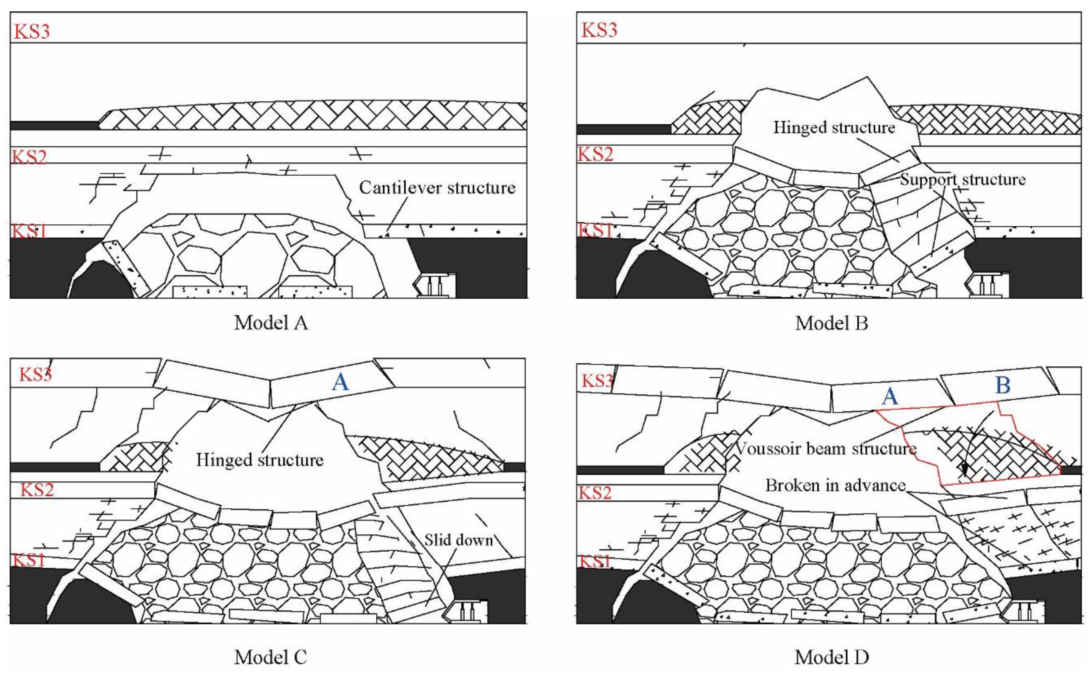
4.1. Structural Models of Roof Strata
- (1)
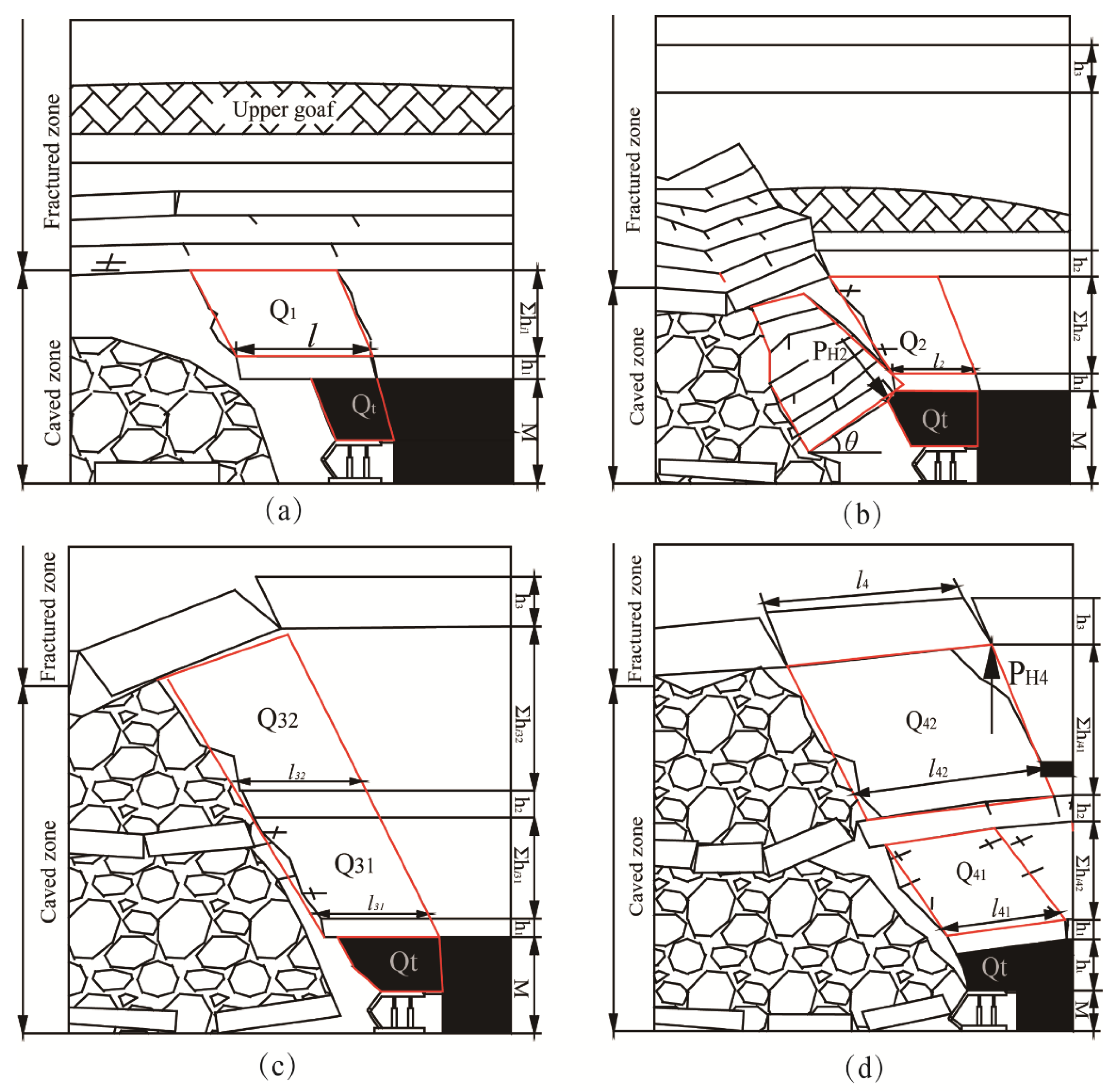
- Model A represents the formation of a cantilever structure in the lower KS. It is characterized by an igneous sill above the coal seam, and part of the roof strata on the working face is controlled by KS1.
- (2)
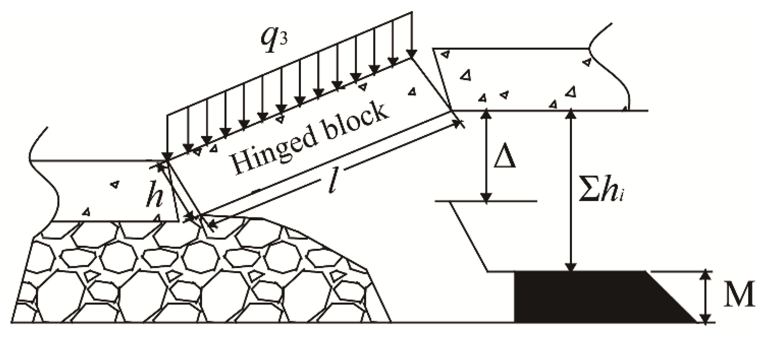
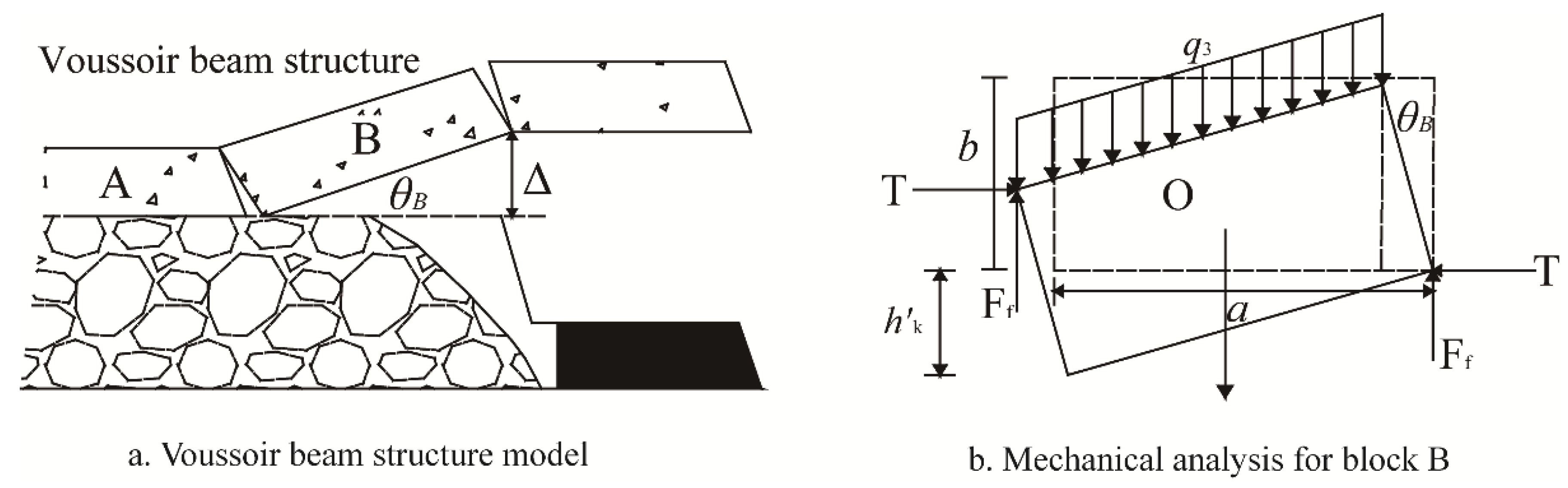
- Model B demonstrates the formation of a support structure in the lower KS and a hinged structure in the middle KS. In this model, the support structure develops from the cantilever structure in model A, and the hinged structure develops from the middle KS2. The movement of the strata between KS1 and KS2 is controlled by the support structure and KS2.
- (3)
- Model C represents the influence between the adjacent KS. In this model, the support structure in KS1 slides down, while the hinged structure in KS2 collapses under the pressure of the broken block in KS3. The behavior of the overlying strata is controlled by the movement of KS1 and KS2.
- (4)
- Model D describes a voussoir beam structure formed in the upper KS3. In this model, a large part of the strata between KS2 and KS3 topple down and break in advance of KS1 and KS2, which are impacted by the break of KS3 and the expanding crack in the upper gob. The strata behavior is controlled by KS3.
4.2. Structural Characteristics of KS
4.3. Support Resistance Determination
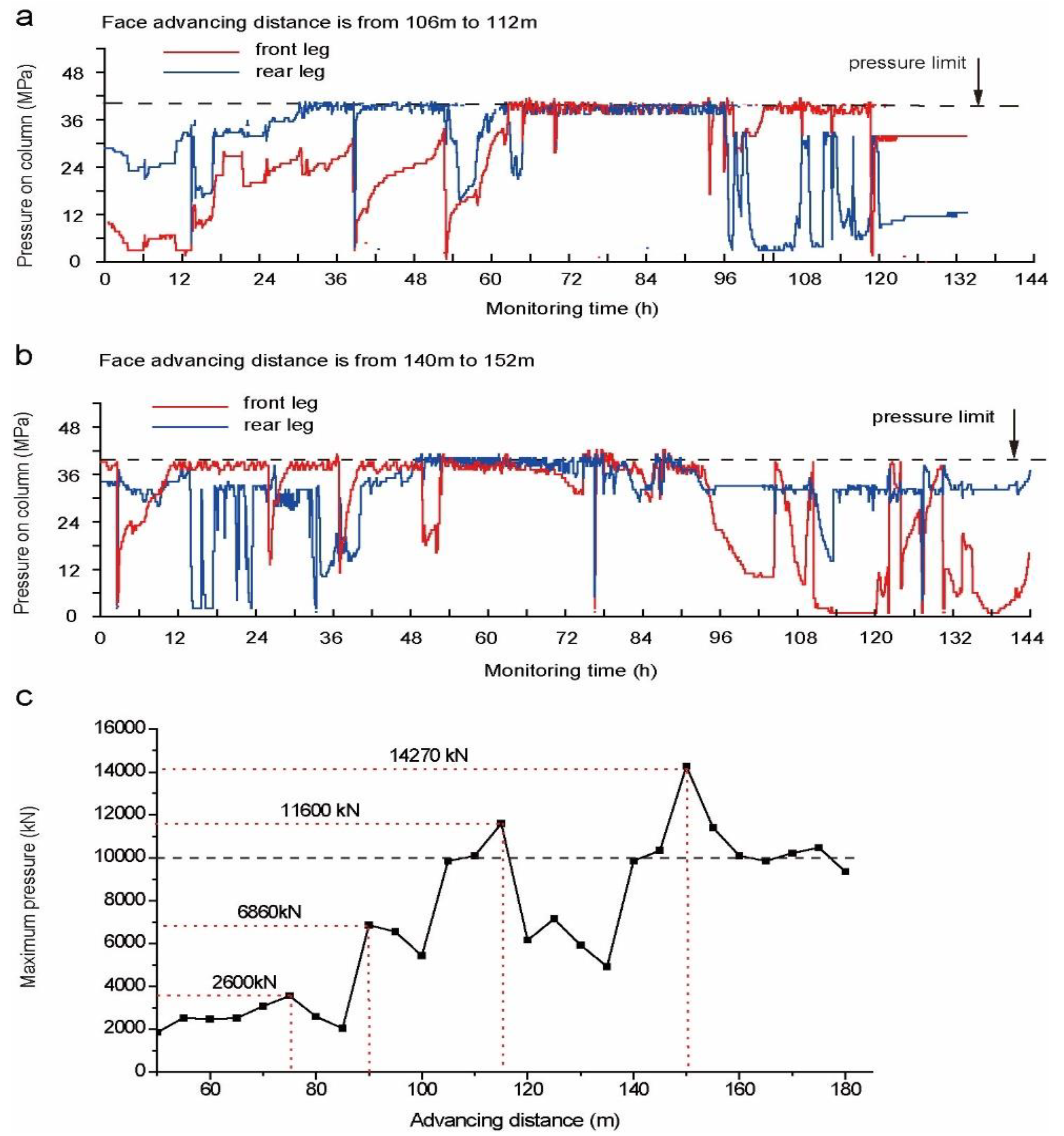
5. Field Mining Pressure
6. Conclusions
Acknowledgments
Author Contributions
Conflicts of Interest
References
- BP. BP Energy Outlook Energy 2017; BP: London, UK, 2017. [Google Scholar]
- Vakili, A.; Hebblewhite, B.K. A new cavability assessment criterion for Longwall Top Coal Caving. Int. J. Rock Mech. Min. Sci. 2010, 47, 1317–1329. [Google Scholar] [CrossRef]
- Alehossein, H.; Poulsen, B.A. Stress analysis of longwall top coal caving. Int. J. Rock Mech. Min. Sci. 2010, 47, 30–41. [Google Scholar] [CrossRef]
- Khanal, M.; Adhikary, D.; Balusu, R. Prefeasibility study—Geotechnical studies for introducing longwall top coal caving in Indian mines. J. Min. Sci. 2014, 50, 719–732. [Google Scholar] [CrossRef]
- Yu, B.; Zhao, J.; Xiao, H. Case Study on Overburden Fracturing during Longwall Top Coal Caving Using Microseismic Monitoring. Rock Mech. Rock Eng. 2017, 50, 507–511. [Google Scholar] [CrossRef]
- Si, G.; Shi, J.Q.; Durucan, S.; Korre, A.; Lazar, J.; Jamnikar, S.; Zavšek, S. Monitoring and modelling of gas dynamics in multi-level longwall top coal caving of ultra-thick coal seams, Part II: Numerical modelling. Int. J. Coal Geol. 2015, 144–145, 58–70. [Google Scholar] [CrossRef]
- Si, G.; Jamnikar, S.; Lazar, J.; Shi, J.Q.; Durucan, S.; Korre, A.; Zavšek, S. Monitoring and modelling of gas dynamics in multi-level longwall top coal caving of ultra-thick coal seams, part I: Borehole measurements and a conceptual model for gas emission zones. Int. J. Coal Geol. 2015, 144–145, 98–110. [Google Scholar] [CrossRef]
- Ju, J.; Xu, J. Surface stepped subsidence related to top-coal caving longwall mining of extremely thick coal seam under shallow cover. Int. J. Rock Mech. Min. Sci. 2015, 78, 27–35. [Google Scholar] [CrossRef]
- Wang, J.; Yu, B.; Kang, H.; Wang, G.; Mao, D.; Liang, Y.; Jiang, P. Key technologies and equipment for a fully mechanized top-coal caving operation with a large mining height at ultra-thick coal seams. Int. J. Coal Sci. Technol. 2015, 2, 97–161. [Google Scholar] [CrossRef]
- Chen, Y.; Ma, S.; Yu, Y. Stability Control of Underground Roadways Subjected to Stresses Caused by Extraction of a 10-m-Thick Coal Seam: A Case Study. Rock Mech. Rock Eng. 2017, 50, 2511–2520. [Google Scholar] [CrossRef]
- Bai, Q.; Tu, S.; Wang, F.; Zhang, C. Field and numerical investigations of gateroad system failure induced by hard roofs in a longwall top coal caving face. Int. J. Coal Geol. 2017, 173, 176–199. [Google Scholar] [CrossRef]
- Kong, D.; Jiang, W.; Chen, Y.; Song, Z.; Ma, Z. Study of roof stability of the end of working face in upward longwall top coal. Arab. J. Geosci. 2017, 10, 185. [Google Scholar] [CrossRef]
- Wang, J.; Yang, S.; Li, Y.; Wei, L.; Liu, H. Caving mechanisms of loose top-coal in longwall top-coal caving mining method. Int. J. Rock Mech. Min. Sci. 2014, 71, 160–170. [Google Scholar] [CrossRef]
- Wang, J.; Zhang, J.; Li, Z. A new research system for caving mechanism analysis and its application to sublevel top-coal caving mining. Int. J. Rock Mech. Min. Sci. 2016, 88, 273–285. [Google Scholar] [CrossRef]
- Wang, L.; Cheng, L.B.; Cheng, Y.; Yin, G.; Xu, C.; Jin, K.; Yang, Q. Characteristics and evolutions of gas dynamic disaster under igneous intrusions and its control technologies. J. Nat. Gas Sci. Eng. 2014, 18, 164–174. [Google Scholar] [CrossRef]
- Lu, C.P.; Liu, Y.; Wang, H.Y.; Liu, P.F. Microseismic signals of double-layer hard and thick igneous strata separation and fracturing. Int. J. Coal Geol. 2016, 160–161, 28–41. [Google Scholar] [CrossRef]
- Xuan, D.; Xu, J.; Zhu, W. Dynamic disaster control under a massive igneous sill by grouting from surface boreholes. Int. J. Rock Mech. Min. Sci. 2014, 71, 176–187. [Google Scholar] [CrossRef]
- Chen, Y.; Watanabe, K.; Kusuda, H.; Kusaka, E.; Mabuchi, M. Crack growth in Westerly granite during a cyclic loading test. Eng. Geol. 2011, 117, 189–197. [Google Scholar] [CrossRef] [Green Version]
- Zhao, T.; Zhang, Z.; Tan, Y.; Shi, C.; Wei, P.; Li, Q. An innovative approach to thin coal seam mining of complex geological conditions by pressure regulation. Int. J. Rock Mech. Min. Sci. 2014, 71, 249–257. [Google Scholar] [CrossRef]
- Qian, M.; Shi, P. Mining Pressure and Strata Control; Qian, M.G., Shi, P.W., Eds.; China University of Mining and Technology Press: Xuzhou, China, 1992. [Google Scholar]
- Qian, M.; Miao, X.; Xu, J. Theoretical study of key stratum in ground control. J. China Coal Soc. 1996, 21, 225–230. [Google Scholar]
- Song, Z.; Jiang, Y.; Liu, J. Theory and model of practical method of mine pressure control. Coal Sci. Technol. Mag. 2017, 2, 1–10. (In Chinese) [Google Scholar]
- Feng, G.; Wang, X.; Kang, L. Analysis on the mechanism of the face-contacted blocks structure in overlying strata above the longwall face. J. China Coal Soc. 2008, 33, 33–37. (In Chinese) [Google Scholar]
- Verma, A.K.; Deb, D. Longwall face stability index for estimation of chock-shield pressure and face convergence. Geotech. Geol. Eng. 2010, 28, 431–445. [Google Scholar] [CrossRef]
- Verma, A.K.; Deb, D. Effect of lithological variations of mine roof on chock shield support using numerical modeling technique. J. Sci. Ind. Res. 2006, 65, 702–712. [Google Scholar]
- Guo, W.; Wang, H.; Dong, G.; Li, L. A case study of effective support working resistance and roof support technology in thick seam fully-mechanized face mining with hard roof conditions. Sustainability 2017, 9, 935. [Google Scholar] [CrossRef]
- Ju, J.; Xu, J. Structural characteristics of key strata and strata behaviour of a fully mechanized longwall face with 7.0 m height chocks. Int. J. Rock Mech. Min. Sci. 2013, 58, 46–54. [Google Scholar]
- Cheng, Y.; Jiang, F.; Pang, J. Research on lateral strata pressure characteristic in goaf of top coal caving in extra thick coal seam and its application. J. China Coal Soc. 2012, 37, 1088–1093. (In Chinese) [Google Scholar]
- Wen, Z.; Zhao, X.; Yin, L.; Xia, H. Study on Mechanical Model and Reasonable Working-Condition Parameters in Mining Stope with Large Mining Height. J. Min. Saf. Eng. 2010, 27, 255–258. (In Chinese) [Google Scholar]
- Yu, L.; Yan, S.; Liu, Q. Determination of support working resistance of top coal caving in extra thick coal seam. J. China Coal Soc. 2012, 37, 737–2742. (In Chinese) [Google Scholar]
- Ning, J.; Wang, J.; Jiang, L.; Jiang, N.; Liu, X.; Jiang, J. Fracture analysis of double-layer hard and thick roof and the controlling effect on strata behavior: A case study. Eng. Fail. Anal. 2017, 81, 117–134. [Google Scholar] [CrossRef]
- Huang, B.; Wang, Y.; Cao, S. Cavability control by hydraulic fracturing for top coal caving in hard thick coal seams. Int. J. Rock Mech. Min. Sci. 2015, 74, 45–57. [Google Scholar] [CrossRef]
- Wang, P.; Jiang, J.; Zhang, P.; Wu, Q. Breaking process and mining stress evolution characteristics of a high-position hard and thick stratum. Int. J. Min. Sci. Technol. 2016, 26, 563–569. [Google Scholar] [CrossRef]
- Huang, P.; Ju, F.; Jessu, K.; Xiao, M.; Guo, S. Optimization and Practice of Support Working Resistance in Fully-Mechanized Top Coal Caving in Shallow Thick Seam. Energies 2017, 10, 1406. [Google Scholar] [CrossRef]
- Li, M.; Zhou, N.; Zhang, J.; Liu, Z. Numerical Modelling of Mechanical Behavior of Coal Mining Hard Roofs in Different Backfill Ratios: A Case Study. Energies 2017, 10, 1–18. [Google Scholar]
- Zhou, N.; Zhang, J.; Hao, Y.; Li, M. Deformation Behavior of Hard Roofs in Solid Backfill Coal Mining Using Physical Models. Energies 2017, 10, 557. [Google Scholar] [CrossRef]
- Xie, G.X.; Chang, J.C.; Yang, K. Investigations into stress shell characteristics of surrounding rock in fully mechanized top-coal caving face. Int. J. Rock Mech. Min. Sci. 2009, 46, 172–181. [Google Scholar] [CrossRef]
- Liu, Y.; Zhou, F.; Liu, L.; Liu, C.; Hu, S. An experimental and numerical investigation on the deformation of overlying coal seams above double-seam extraction for controlling coal mine methane emissions. Int. J. Coal Geol. 2011, 87, 139–149. [Google Scholar]
- Lin, Y. Experimental Rock Mechanics—Simulation Study; Beijing Industry Press: Beijing, China, 1984. [Google Scholar]
- Zhou, A. Research on Geology of Datong Late Paleozoic Coal-Bearing Basin; China Coal Industry Press: Beijing, China, 2010. [Google Scholar]
- Guo, J.; Feng, G.; Guo, Y.; Qi, T.; Zhang, Y.; Ren, A.; Kang, L.; Guo, G. Mechanical property variation under dynamic uniaxial compression and mechanism of lamprophyre in saturated state. J. China Coal Soc. 2015, 40, 323–330. (In Chinese) [Google Scholar]
- Li, Z.; Guo, J.; Feng, J. Experiment Research on Mechanical Property of Lamprophyre in Nature and Saturated Conditions. Chin. J. Undergr. Sp. Eng. 2014, 10, 1039–1046. (In Chinese) [Google Scholar]
- Deere, D. The Rock Quality Designation (RQD) Index in Practice; ASTM International: West Conshohocken, PA, USA, 1988. [Google Scholar]
- Liu, Z.; Dang, W. Rock quality classification and stability evaluation of undersea deposit based on M-IRMR. Tunn. Undergr. Sp. Technol. 2014, 40, 95–101. [Google Scholar] [CrossRef]
- Yan, R.; Shen, Y. Correlation of Revised BQ System in China and the International Rock Mass Classification Systems. J. Civ. Eng. Res. 2015, 5, 33–38. [Google Scholar]
- Yan, T.; Wu, X.; Wu, L. Correlation Study on Surrounding Rockmass Classification for Underground Cavern and Its Application. Chin. J. Undergr. Sp. Eng. 2009, 5, 1103–1109. (In Chinese) [Google Scholar]
- Xu, J.; Qian, M. Method to Disting ui sh Key St rata in Ov erburden. J. China Univ. Min. Technol. 2000, 29, 463–467. (In Chinese) [Google Scholar]
- China Coal Industry Press. State Administration of Work Safety Coal Mine Safety Regulation; China Coal Industry Press: Beijing, China, 2016. [Google Scholar]
- Qian, M.; Miao, X.; He, F. Analysis of key block in the structure of voussoir beam in longwall mining. J. China Coal Soc. 1994, 19, 557–563. (In Chinese) [Google Scholar]


| No. | Rock Strata | Unit Weight () | Elastic Modulus () | Friction Angle () | Cohesion () | Poisson’s Ratio |
|---|---|---|---|---|---|---|
| 1 | Siltstone | 23.5 | 18.5 | 37 | 15.2 | 0.24 |
| 2 | Fine grained sandstone | 25.6 | 36.0 | 47 | 24.5 | 0.18 |
| 3 | Quartz sandstone | 26.5 | 28.2 | 38 | 20.6 | 0.22 |
| 4 | Silty mudstone | 25.1 | 27.5 | 37 | 14.4 | 0.24 |
| 5 | Medium-coarse sandstone | 25.3 | 21.5 | 31 | 10.2 | 0.17 |
| 6 | Glutenite | 27.0 | 28.5 | 42 | 23.5 | 0.20 |
| 7 | Fine sandstone | 26.0 | 38.1 | 47 | 23.6 | 0.15 |
| 8 | Sandy mudstone | 25.9 | 35.1 | 33 | 8.3 | 0.22 |
| 9 | Lamprophyre | 27.4 | 60.9 | 52 | 24.8 | 0.12 |
| 10 | Coal | 14.3 | 8.4 | 28 | 14.3 | 0.32 |
| Structural Model | Model A | Model B | Model C | Model D |
|---|---|---|---|---|
| Load (kN) | 2570 | 6250 | 12,150 | 14,850 |
© 2018 by the authors. Licensee MDPI, Basel, Switzerland. This article is an open access article distributed under the terms and conditions of the Creative Commons Attribution (CC BY) license (http://creativecommons.org/licenses/by/4.0/).
Share and Cite
Guo, J.; Feng, G.; Wang, P.; Qi, T.; Zhang, X.; Yan, Y. Roof Strata Behavior and Support Resistance Determination for Ultra-Thick Longwall Top Coal Caving Panel: A Case Study of the Tashan Coal Mine. Energies 2018, 11, 1041. https://doi.org/10.3390/en11051041
Guo J, Feng G, Wang P, Qi T, Zhang X, Yan Y. Roof Strata Behavior and Support Resistance Determination for Ultra-Thick Longwall Top Coal Caving Panel: A Case Study of the Tashan Coal Mine. Energies. 2018; 11(5):1041. https://doi.org/10.3390/en11051041
Chicago/Turabian StyleGuo, Jun, Guorui Feng, Pengfei Wang, Tingye Qi, Xiaorong Zhang, and Yonggan Yan. 2018. "Roof Strata Behavior and Support Resistance Determination for Ultra-Thick Longwall Top Coal Caving Panel: A Case Study of the Tashan Coal Mine" Energies 11, no. 5: 1041. https://doi.org/10.3390/en11051041