A Proportional Resonant Controller for Suppressing Resonance in Grid Tied Multilevel Inverter


Department of Electrical and Electronics Engineering, SRM Institute of Science & Technology, Chennai 603203, India
*
Author to whom correspondence should be addressed.
Energies 2018, 11(5), 1024; https://doi.org/10.3390/en11051024
Submission received: 28 February 2018
/
Revised: 29 March 2018
/
Accepted: 13 April 2018
/
Published: 24 April 2018
(This article belongs to the Special Issue International Conference on Renewable Energy Research and Applications (ICRERA-2017))
Abstract
:Photovoltaic (PV) resources are connected to power grid through voltage source inverters. The quality of power output from PV inverter should be in grid compliance of IEEE standard. In this regard, the deployment of appropriate low pass filters such as inductor (L), capacitor (C) or inductor capacitor inductor (LCL) is critical as they aid in minimizing the harmonics being injected into the grid. LCL filters are well entrenched but they bring in stability issue due to resonance and therefore a damping controller with suitable control logic is needed. In this work, to suppress resonance, a Proportional Resonant-Derivative (PR-D) controller has been designed, proposed, and compared with existing counterparts, i.e., two-degree of freedom controller (2DOF) and feedback current controller. The results exhibits that PR-D controller admits meliorate resonance damping and constancy when compared with the two other schemes. The whole system has been simulated in MATLAB/Simulink environment and a prototype has also been made to ensure the performance.
1. Introduction
Photovoltaic (PV) power generation has become the most promising way of power generation among the renewable sources due its inherent advantages. The major hurdle that PV system faces, similar to other renewable sources, is the power intermittency with respect to atmospheric conditions such as irradiation and temperature. With the advent of advanced controllers and efficient dc-dc converters, the intermittency issues are meritoriously addressed [1]. In a contemporary note, many novel dc-dc converters have been introduced in research arena, but the appeal remains the same in case of the three well entrenched converters, i.e. buck, boost, and buck boost converters. The choice of dc-dc converters depends on the voltage levels of source and load. The role of the dc-dc converters in PV system is very critical, as it only regulates the voltage but also makes most of the PV power available through an intelligent maximum power tracking (MPPT) algorithm [2]. MPPT facilitates the yield of maximum available power for the given atmospheric conditions. Numerous MPPT algorithms have been archived in research forum [3]. The modified and new MPPT algorithms claimed to be novel either in alleviating the complexity involved in execution of the algorithm in real time or in making the algorithm not prone to oscillations and inaccuracies [4]. Nevertheless, two well established MPPT algorithms, perturb and observe (P&O) and incremental conductance (INC), remain the most prevalent choices in the PV industry [5]. P&O is a simple and cost effective MPPT controller but the oscillation in the power output due to the inherent comparative search mechanism is indispensable. INC, on the other hand, is the most promising algorithm, as it is efficient and not oscillatory like its counterpart [6], and remains the most prominent and highly recommended MPPT algorithm.
PV with MPPT aided dc-dc converters need to be interfaced with inverters when it serves AC loads or grid. The output voltage profile, the switching losses/stress, stability issues and its total harmonic distortion (THD) are the direct indicators for the performance of the inverter. The THD of the inverter is considerably reduced when the choice of the inverter topology and the switching techniques are done prudently [7]. There are several switching techniques proposed in research platform and these techniques possess their own merits and demerits. The sinusoidal pulse width modulation (SPWM) technique still lingers as the simplest and most effective one [8]. Pertaining to the topological modifications, multilevel inverter (MLI) since its inception has been the most effective power converter in terms of handling high voltage and high power [9]. The research articles archived pertaining to several topologies of MLI is huge and among them reduced cascaded MLI is most attracting one [10]. Recently, there has been a considerable increase in the importance of multilevel inverters, since they do not rely on just two levels of voltage to create an AC signal. Alternatively, different voltage levels are combined to each other resulting in a smoother stepped waveform with less dv/dt and lower harmonic distortions. There are several types of topologies of a multilevel inverter to produce a stepped waveform, including neutral clamped diode MLI (NPCMLI), flying capacitor multilevel inverter and so on. The inherent quality power output of MLI has attracted researchers to explore new topologies in MLI [11,12,13]. Among all MLI topologies, the reverse voltage topology MLI (RVT MLI) is famous in research arena for its reduced switch count. This particular topology is very compatible with distributed sources such as PV, fuel cell etc., as the sources of medium power can be easily cascaded to constitute a higher capacity inverter. On the other hand, since the topology has a cascaded unit structure, factors such as voltage stress on the switch, switching loss, and the issues with selection of the switch are easily sorted [14]. Several articles have been archived in the field of modular multilevel converters; Mehrasa has done extensive research in analyzing the regulation of the modular inverter and its stability aspects during varying load parameters [15,16].
PV MLI with grid interface should comply with the grid standard and therefore filters selection and design is critical [17,18]. The selection of the LCL filter is the best choice since it has advanced aspects [18] in comparison with other filters. PV as a source injects current into the grid once the inverter output is synchronized with grid with respect to voltage and frequency, and therefore it is vital that the profile of the current is sinusoidal to lessen the harmonic impact. The typical PI controller based structure may be a weak candidate for mitigating the current harmonic issue due to the bandwidth limitation [19,20,21]. To augment the bandwidth a high proportional controller is always preferred but the major hurdle witnessed here is that the system stability may become unwieldy if the LC tunes resonance for a particular ripple frequency. Therefore, control logic and damping methods become crucial parameters in grid synchronized system. Although some research addressed PR controller in PV grid interfaces, less research addressed PV grid interfaces through MLI having PR controller. This study had that unique feature and, in this work, PR-D controller was considered by which the damping was done up to−0.16db, thus exhibiting improved operation. The proposed method was duly compared with its similar counterpart 2DOF active damping. The detailed stability analysis of the proposed structure clearly envisaged the merits of the proposed system. The paper is as follows. Section 2 deals with PV modeling with MPPT scheme and the grid interactive MI. The proposed system is described and it is compared with other prevailing techniques in Section 3.The concluding remarks are presented in Section 4.
2. System Description
Figure 1 shows system topology of grid interfaced reverse voltage topology MLI with LCL filter. This topology comprises PV Panel, MPPT aided boost converter and a multilevel inverter unit that facilitates single-phase seven-level stepped output and LCL filter connecting the inverter output to the grid and controller to regulate the inverter.
2.1. PV Array Modeling
The equivalent circuit of a PV cell is shown in Figure 2.
The photovoltaic panel can be modeled mathematically as given in Equations (1)–(4).
Module photon current:
Modules reverse saturation current:
Module saturation current I0 differs with the cell temperature:
The current output of PV module:
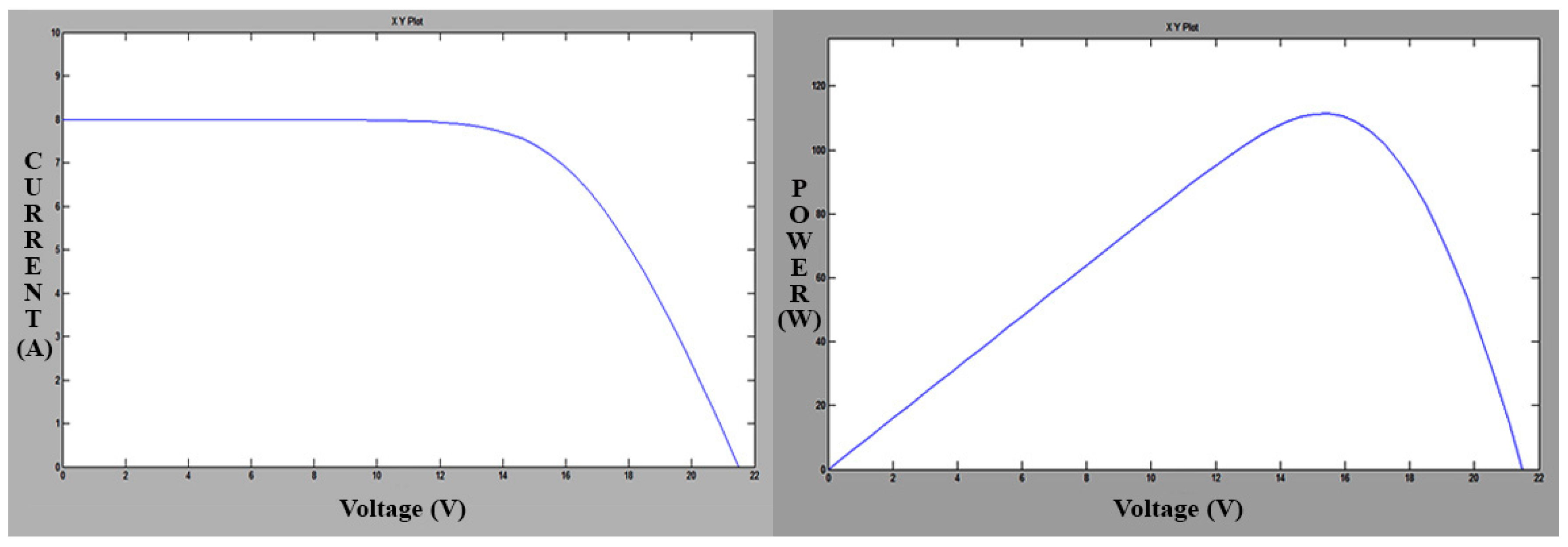
By the advanced formulations, the PV module features are predicted, as shown in Figure 3. To meet the necessary specifications of the application, the output of the PV module is boosted by means of a power converter.
2.2. MPPT Controller
The MPPT unit will make sure that maximum power is rendered to the grid for the given atmospheric conditions. Many algorithms have been administered so far in the research forum and this work adopted incremental conductance (INC) method of MPPT. The INC method is superior to its close competitor perturb and observe (P&O) in terms of reliable, oscillation free power output. The flow diagram of INC MPPT is given in Figure 4.
The incremental conduction MPPT checks for the change are slope value of the power with respect to voltage and propagates towards the peak power, i.e., if dP/dV is negative, then MPPT will be on the right side of the current position, while, if it is positive, then the peak will be situated on the left of the current search point.
2.3. Grid Interfaced RVT MLI
By comparison of the above mentioned MLI types, the reverse voltage multilevel inverter was projected during 2008 as a new topology to challenge the existing popular topologies. The circuit diagram of RVTMLI is shown in Figure 5.
Modes of Operation of RVT MLI
Switching sequence in this inverter is very simple. While selecting a particular switching pattern, make sure that switching transitions are minimum. There are six switching patterns to control the inverter. The sequence of switches (2-3-4), (2-3-5), (2-6-5), and (1-5) are used for levels 0–3, respectively. The output voltage will be the sum of voltage sources that are included in the current path. Current path for each level is shown in Figure 6 according to the above switching pattern.
The number of components is determined using the equations given below:
where, M is the number of levels, Mcarriers is the required number of carriers, and Mdc is the required number of DC sources.
Mswitch = [(M − 1) + 4]
Mcarriers or Mdc = (M − 1)/2
The total number of components (Tc) is given by,
Tc = {[(M − 1) + 4] + Mcarriers + Mdc}
For 60-degree PWM method, modulating sine wave is flat topped for a period of 60 degrees in each half cycle, as shown in Figure 7.
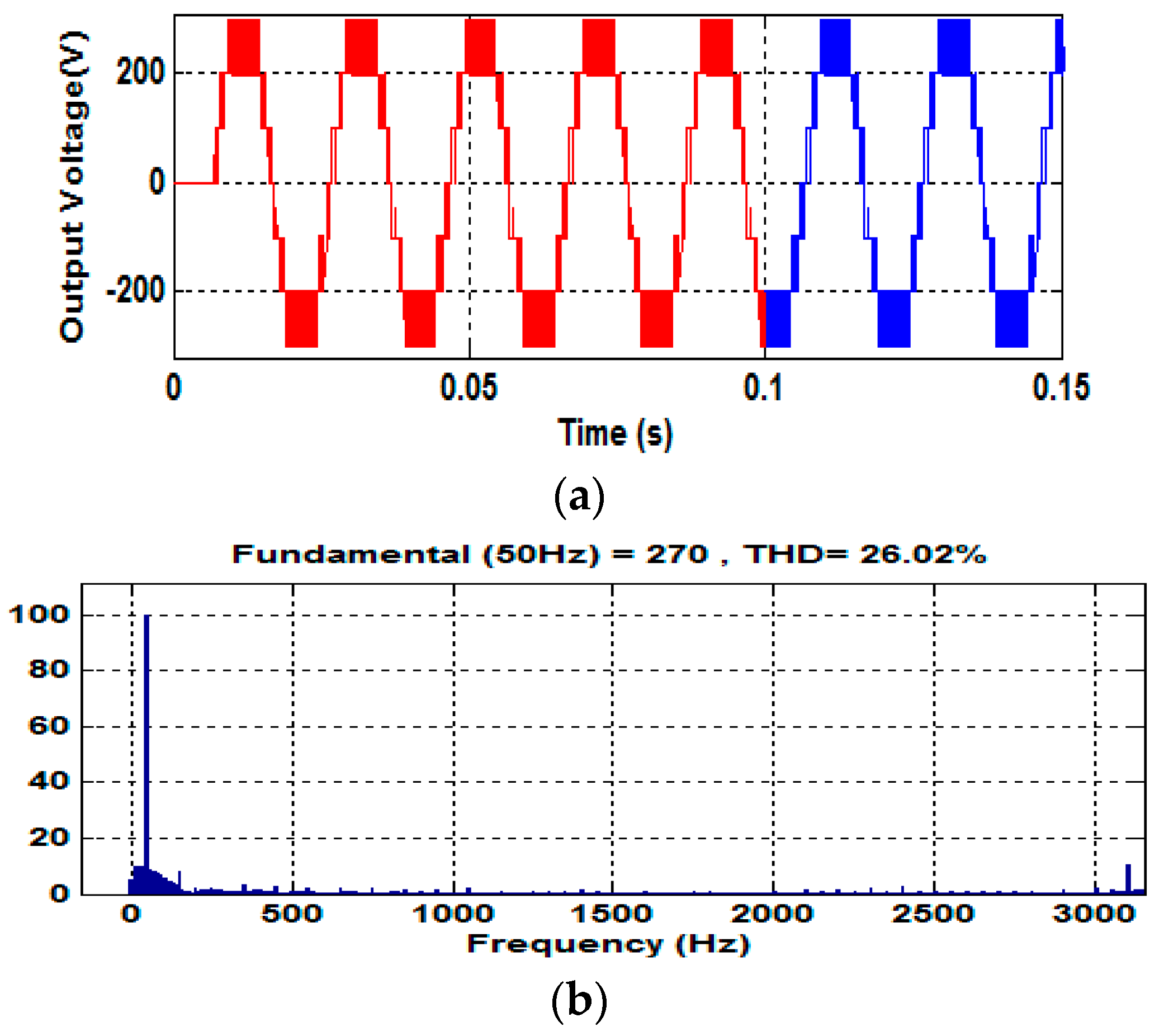
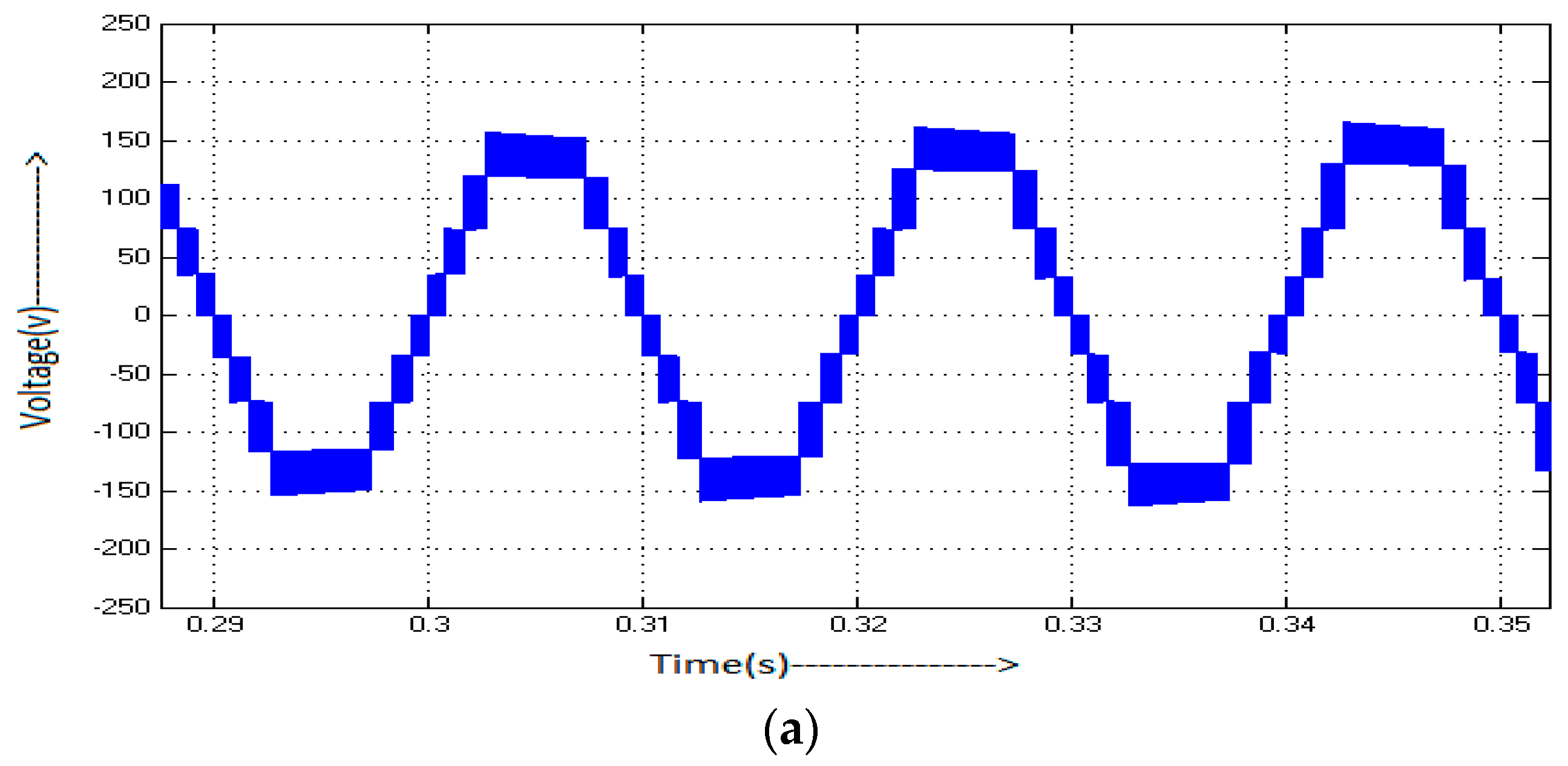
The simulated single-phase seven-level output voltage and harmonic spectrum with PWM is shown in Figure 8a,b.
In Figure 8b, the sinusoidal output voltage of the reverse voltage topology multilevel inverter has less total harmonic distortion and no even or triplen harmonics. LCL filter is used to integrate RVT MLI and grid whose function is to get rid of the current harmonics injected to the grid. Thus, output of the inverter is connected to the LCL filter, which is explained in flowing sections.
2.4. Grid Interfaced Inverter with LCL Filter
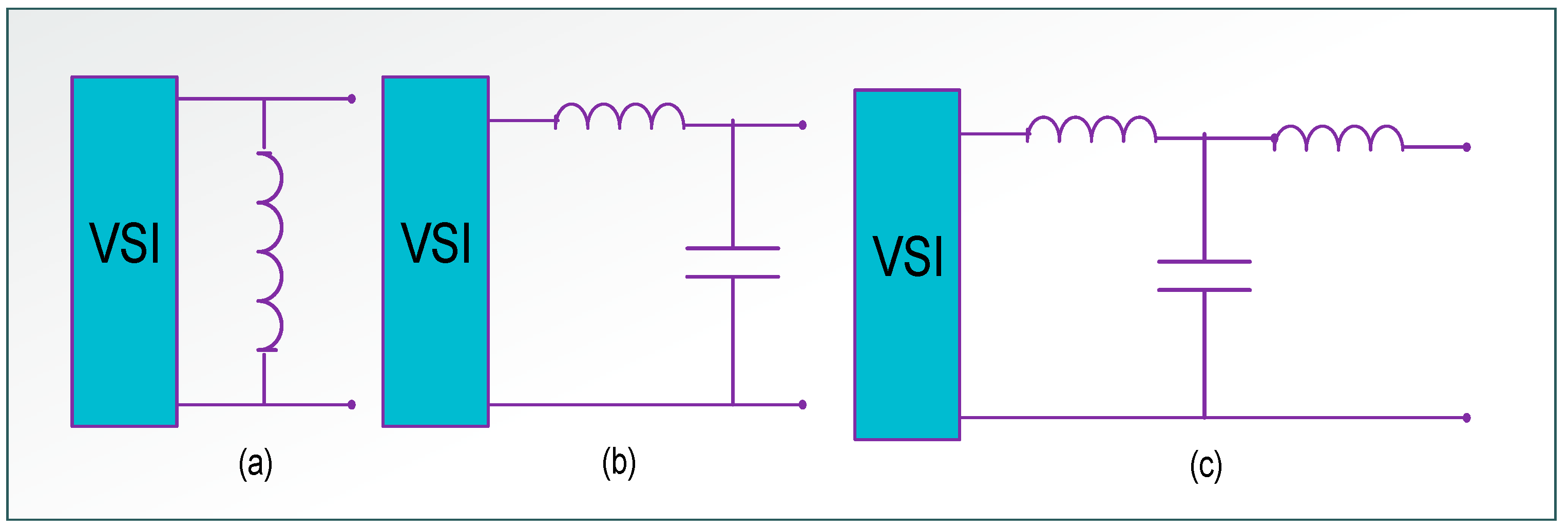
The PWM inverter is connected to the grid by LCL filter that acts as low pass filter to filter out higher order harmonics. However, LCL filter injects two complex conjugate poles to the system and thus generates resonance in the system. The possible topologies are shown in Figure 9.
Modeling of grid interfaced inverter with LCL Filter
BY KVL and KCL equations were applied:
To evaluate the system, the state-space model should be transformed into the standard canonical form. The state variables selected are
By differentiating Equation (8),
Therefore, the system is formulated in canonical form as follows:
The transfer function of LCL filter is shown below and the filter model is shown in Figure 10. Applying KVL and KCL to LCL filter, the transfer function of LCL filter is given by
The transfer function of LCL filter with damping resistor (Rd) is given as
The cut-off frequency of the filter can be calculated as
The parameters of the design filter and parameters required for filter design are summarized in Table 1.
The Bode plot of the inverter with the designed LCL filter without damping is shown in Figure 11 and the resonance peak is observed between 0 and 123 db at 1305 Hz.
3. PR-D Prevails over Two Degrees and Current Feedback Controller
From the Bode plot in Figure 11, it is apparent that this filter introduces resonance to the system that causes generation of harmonics and distortion in voltage and current fed to grid.
Using Figure 12, two degrees of freedom controller is designed and the simulated output voltage is shown in Figure 13. We can say that the resonance peak is observed between −6 and −8 db at 1305 Hz.
The block diagram of injected grid current feedback controller [22] is shown in Figure 14a and the relevant frequency response is shown in Figure 14b, where kg is the factor of the feed forward grid voltage (here, kg = 1), iref is the reference current and Gc(s) is the gain of the current regulator, which is used to track iref.
It can be observed in Figure 15 that the injected grid current has a resonance peak of at 1305 Hz. Using PR-D controller, the resonant peak is reduced to −0.15 db. The block diagram of proposed PR-Controller is shown in Figure 16. In this section, the prevailing two degrees of freedom controller and grid injected current controller schemes are compared with the suggested PR-D controller.
PR controller was incorporated in this study to enhance the accuracy of the control system. The important characteristic feature is at resonance frequency to contribute infinite gain. This controller has the ability to compensate known and fixed frequency. Signals that are controlled by PRD controller are given to the PWM.
GPR is the transfer function of PR (proportional resonant) controller, which is given as
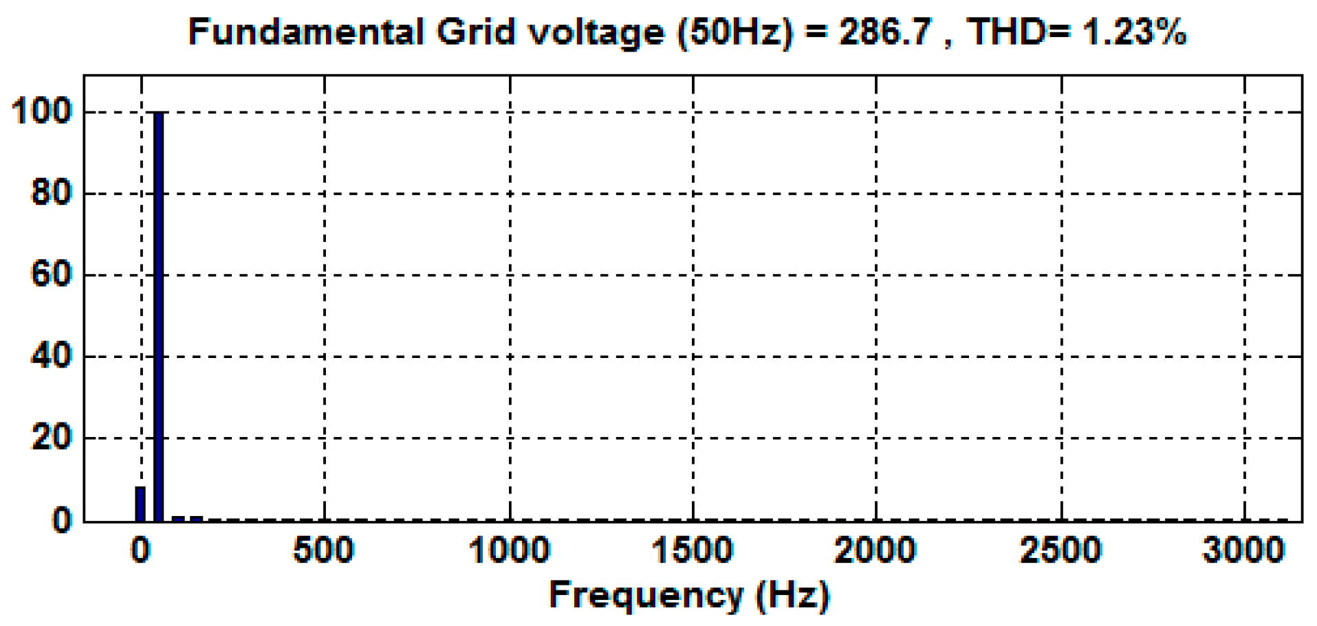
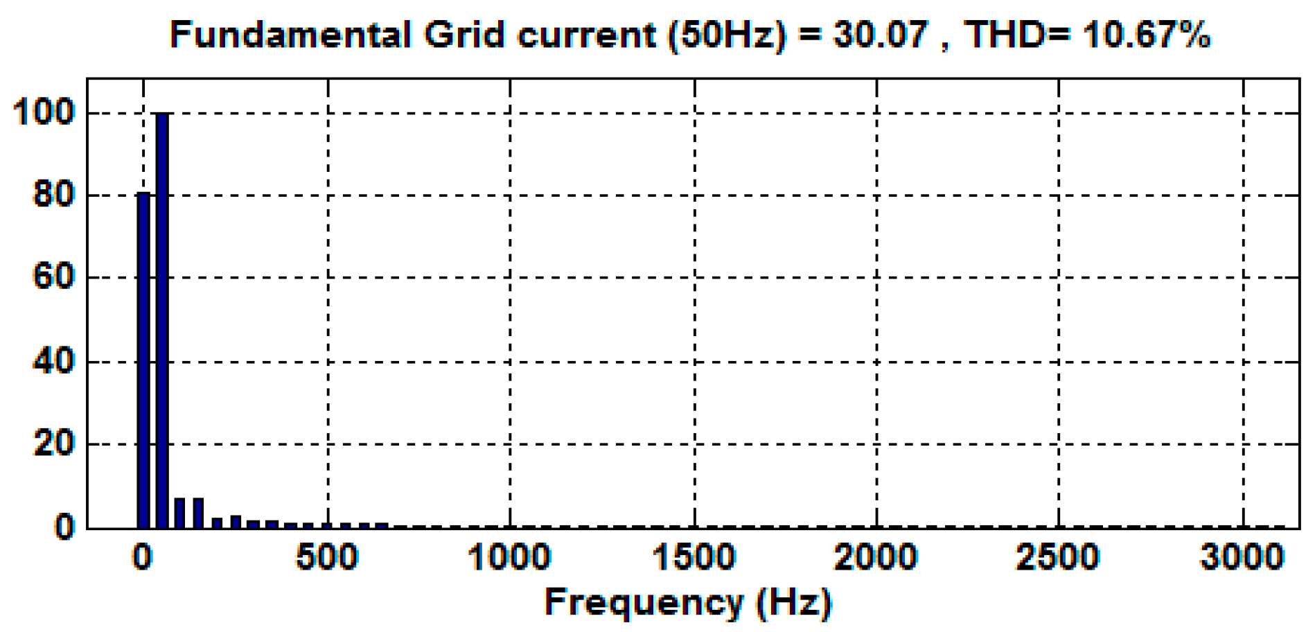
where Kp is the proportional gain tuned in the same manner as performed for a PI controller, and it mainly decides the dynamics of the system in terms of bandwidth, phase, and gain margin. The simulated harmonic spectrum analysis of output voltage and grid injected current is shown in Figure 17 and Figure 18, respectively. The THD values comply to the industrial standard and IEEE 519-1992 as the voltage harmonics are below 3% and the current harmonics are also less at PCC.
Bode plot is drawn with PR-D controller fed LCL filter (Figure 19), and we can distinguish that the resonant peak is reduced, which is observed between −0.15 and 0 db at 1305 Hz. This shows the improved performance of the system with PR controller when compared to the two degrees of freedom controller and grid injected feedback current controllers.
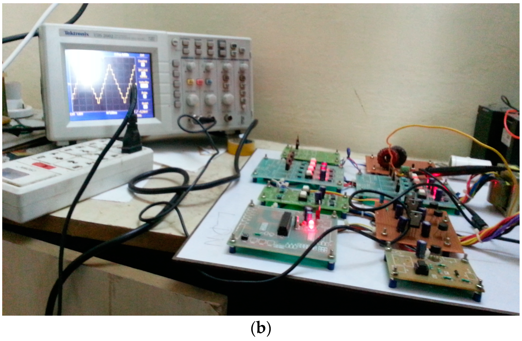
The hardware output for seven-level MLI is shown in Figure 20a and the whole prototype setup is shown in Figure 20b. The experimental hardware platform presents the MLI output. The grid synchronization in real time is achieved through zero crossing detectors (ZCD) with phase locked loop (PLL) circuitry.
4. Conclusions
A PR-D controller-based resonance damping technique is projected in this paper to enhance the dynamic response of overall system and effectively reduce the current component. In a grid linked inverter, although the third order low pass LCL filter can filter out the output harmonics, it introduces resonance at a particular frequency. Active damping is more flexible and does not cause power loss such as in passive damping. The proposed PR-D controller combines the effect of proportional resonant (PR) and derivative (D) controller to dampen the resonance.
It has been found that, although 2DOF (PI-D) controller and grid injected feedback current controllers can dampen the resonance, they fail to remove the resonance completely. The proposed PR-D controller dampens the resonance to the maximum possible limit and hence is better when compared to its counterparts. Simulation results and mathematical analysis confirmed the effectiveness of the PR-D controller. In addition, a hardware prototype was realized, accordingly.
Author Contributions
All authors contributed equally to the final dissemination of the proposed research work as full article.
Conflicts of Interest
The authors declare that there is no conflict of interests regarding the publication of this paper.
References
- Azary, M.T.; Sabahi, M.; Babaei, E.; Meinagh, F.A.A. Modified Single-Phase Single-Stage Grid-Tied Flying Inductor Inverter with MPPT and Suppressed Leakage Current. IEEE Trans. Ind. Electr. 2018, 65, 221–231. [Google Scholar] [CrossRef]
- Onar, O.C.; Kobayashi, J.; Erb, D.C.; Khaligh, A. A Bidirectional High-Power-Quality Grid Interface with a Novel Bidirectional Noninverted Buck–Boost Converter for PHEVs. IEEE Trans. Veh. Technol. 2012, 61, 2018–2032. [Google Scholar] [CrossRef]
- Hanif, M.; Khadkikar, V.; Xiao, W.; Kirtley, J.L. Two Degrees of Freedom Active Damping Technique for LCL Filter-Based Grid Connected PV Systems. IEEE Trans. Ind. Electr. 2014, 61, 2795–2803. [Google Scholar] [CrossRef]
- Jones, M.; Vukosavic, S.N.; Dujic, D.; Levi, E.; Wright, P. Five-leg inverter PWM technique for reduced switch count two-motor constant power applications. IET Electr. Power Appl. 2008, 2, 275–287. [Google Scholar] [CrossRef]
- Sharma, R.K.; Mishra, S. Dynamic Power Management and Control of a PV PEM Fuel-Cell-Based Standalone Ac/Dc Microgrid Using Hybrid Energy Storage. IEEE Trans. Ind. Appl. 2018, 54, 526–538. [Google Scholar] [CrossRef]
- Yang, F.; Xia, N.; Han, Q.L. Event-Based Networked Islanding Detection for Distributed Solar PV Generation Systems. IEEE Trans. Ind. Inform. 2017, 13, 322–329. [Google Scholar] [CrossRef]
- Jeong, H.-G.; Kim, G.-S.; Lee, K.-B. Second-Order Harmonic Reduction Technique for Photovoltaic Power Conditioning Systems Using a Proportional-Resonant Controller. Energies 2013, 6, 79–96. [Google Scholar] [CrossRef]
- Hu, G.; Chen, C.; Shanxu, D. New Active damping strategy for LCL filter based grid connected inverters with harmonics compensation. J. Power Electr. 2013, 13, 287–295. [Google Scholar] [CrossRef]
- Yao, W.; Chen, M.; Matas, J.; Guerrero, J.M.; Qian, Z.M. Design and Analysis of the Droop Control Method for Parallel Inverters Considering the Impact of the Complex Impedance on the Power Sharing. IEEE Trans. Ind. Electr. 2011, 58, 576–588. [Google Scholar] [CrossRef]
- Wu, W.; He, Y.; Tang, T.; Blaabjerg, F. A New Design Method for the Passive Damped LCL and LLCL Filter-Based Single-Phase Grid-Tied Inverter. IEEE Trans. Ind. Electr. 2012, 60, 4339–4350. [Google Scholar] [CrossRef]
- Hanif, M.; Khadkikar, V.; Xiao, W.; James, K.L. Two degrees of freedom active damping technique for LCL filter-based grid connected PV systems. IEEE Trans. Ind. Electr. 2014, 61, 2795–2803. [Google Scholar] [CrossRef]
- Zhang, J.; Zheng, W.X. Design of Adaptive Sliding Mode Controllers for Linear Systems via Output Feedback. IEEE Trans. Ind. Electr. 2014, 61, 3553–3562. [Google Scholar] [CrossRef]
- Mehrasa, M.; Pouresmaeil, E.; Catalao, J.P.S. Direct Lyapunov Control Technique for the Stable Operation of Multilevel Converter Based Distributed Generation in Power Grid. IEEE J. Emerg. Sel. Top. Power Electr. 2014, 2, 931–941. [Google Scholar] [CrossRef]
- Mehrasa, M.; Pouresmaeil, E.; Akorede, M.F.; Jorgensen, B.N.; Catalao, J.P.S. Multilevel converter control approach of active power filter for harmonics elimination in electric grids. Energy 2015, 84, 722–731. [Google Scholar] [CrossRef]
- Mehrasa, M.; Pouresmaeil, E.; Akorede, M.F.; Zabihi, S.; Catalao, J.P.S. Function-based modulation control for modular multilevel converters under varying loading and parameters conditions. IET Gener. Transm. Distrib. 2017, 11, 3222–3230. [Google Scholar] [CrossRef]
- Mehrasa, M.; Pouresmaeil, E.; Taheri, S.; Vechiu, I.; Catalao, J.P.S. Novel Control Strategy for Modular Multilevel Converters Based on Differential Flatness Theory. IEEE J. Emerg. Sel. Top. Power Electr. 2017, 99. [Google Scholar] [CrossRef]
- Mehrasa, M.; Pouresmaeil, E.; Akorede, M.F.; Zabihi, S.; Catalao, J.P.S. A multi-loop control technique for the stable operation of modular multilevel converters in HVDC transmission systems. Int. J. Electr. Power Energy Syst. 2018, 96, 194–207. [Google Scholar] [CrossRef]
- Zhang, N.; Tang, H.; Yao, C. A Systematic Method for Designing a PR Controller and Active Damping of the LCL Filter for Single-Phase Grid-Connected PV Inverters. Energies 2014, 7, 3934–3954. [Google Scholar] [CrossRef]
- Lorzadeh, I.; Abyaneh, A.H.; Savaghebi, M.; Bakhshai, A.; Guerrero, J.M. Capacitor Current Feedback-Based Active Resonance Damping Strategies for Digitally-Controlled Inductive-Capacitive-Inductive-Filtered Grid-Connected Inverters. Energies 2016, 9, 642. [Google Scholar] [CrossRef]
- Zhang, W.; Remon, D.; Cantarellas, A.M.; Rodriguez, P. A Unified Current Loop Tuning Approach for Grid-Connected Photovoltaic Inverters. Energies 2016, 9, 723. [Google Scholar] [CrossRef]
- Espi, J.M.; Garcia-Gil, R.; Castello, J. Capacitive Emulation for LCL-Filtered Grid-Connected Converters. Energies 2017, 10, 930. [Google Scholar] [CrossRef]
- Xu, J.; Xie, S.; Tang, T. Active damping-based control for grid-connected LCL-filtered inverter with injected grid current feedback only. IEEE Trans. Ind. Electr. 2014, 61, 4756–4758. [Google Scholar] [CrossRef]
Figure 1.
Grid interfaced RVT multi-level inverter fed with LCL filter.

Figure 2.
PV cell equivalent circuit.
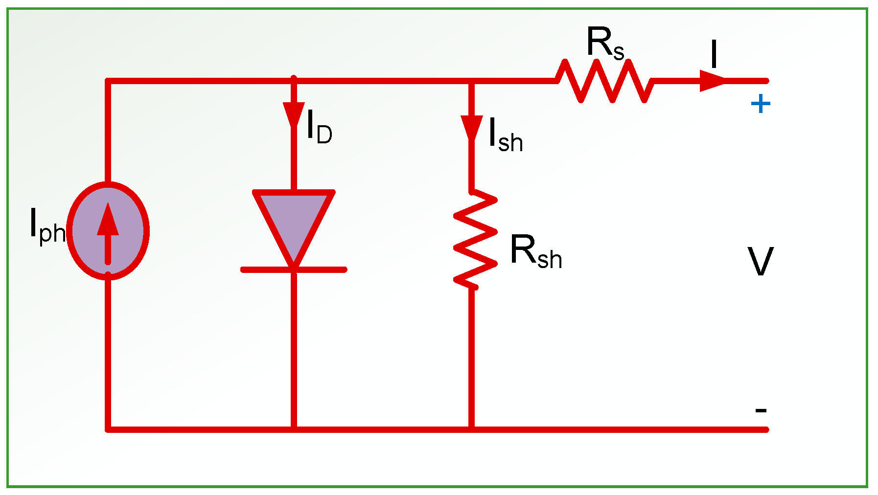
Figure 3.
I-V characteristics and P-V characteristics.

Figure 4.
INC MPPT.
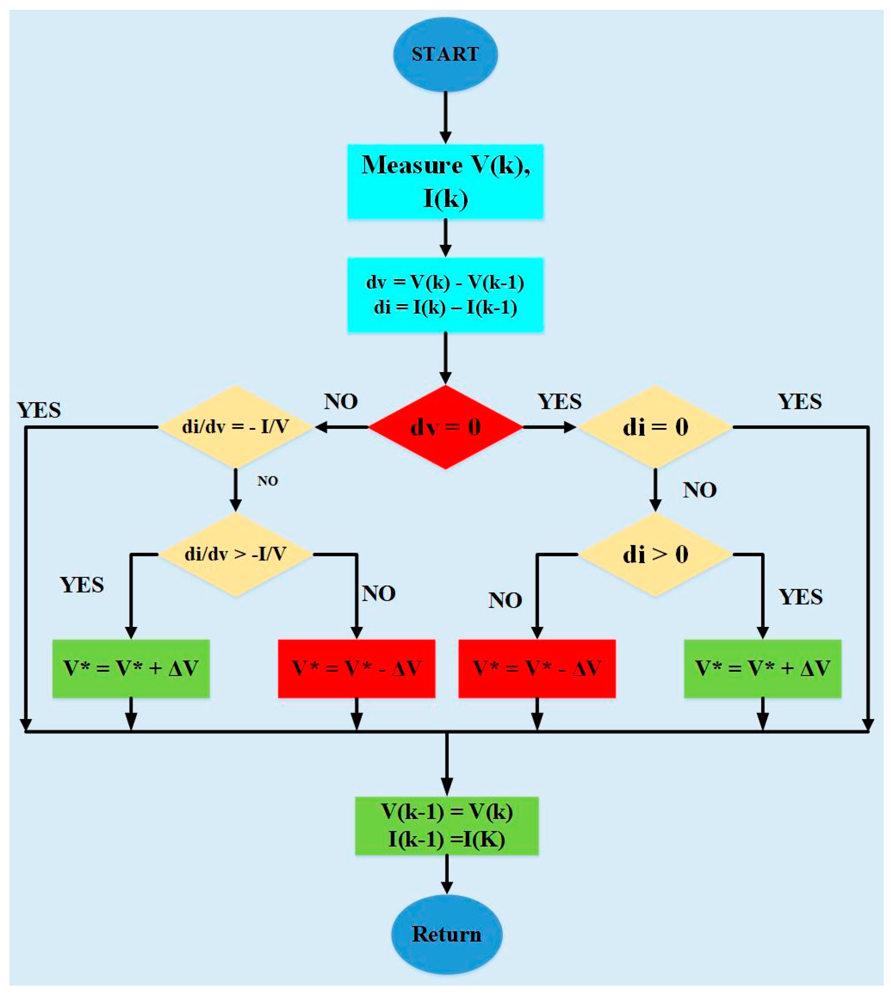
Figure 5.
Single-phase multi-level inverter RV topology.
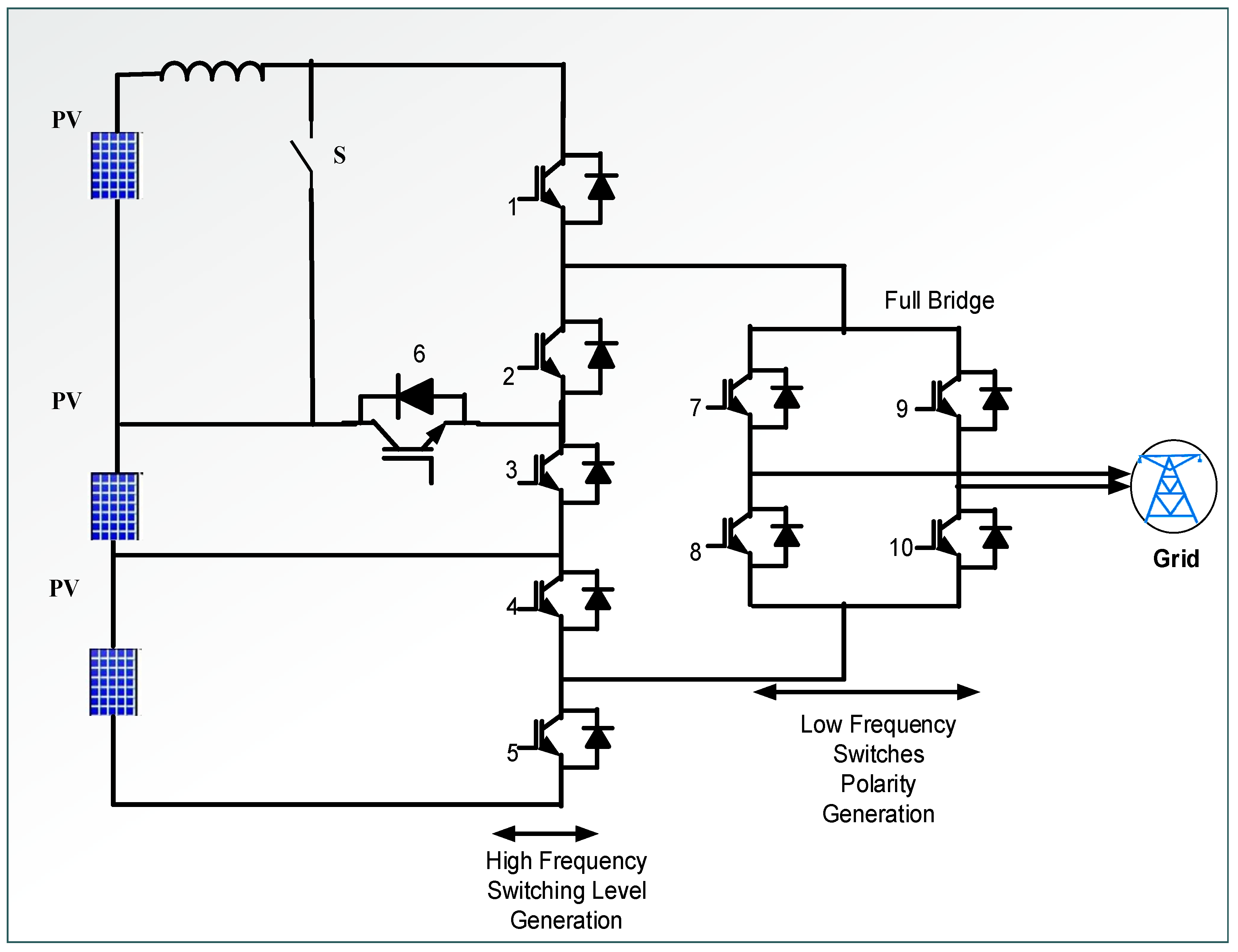
Figure 6.
Switching sequence of RVT MLI.
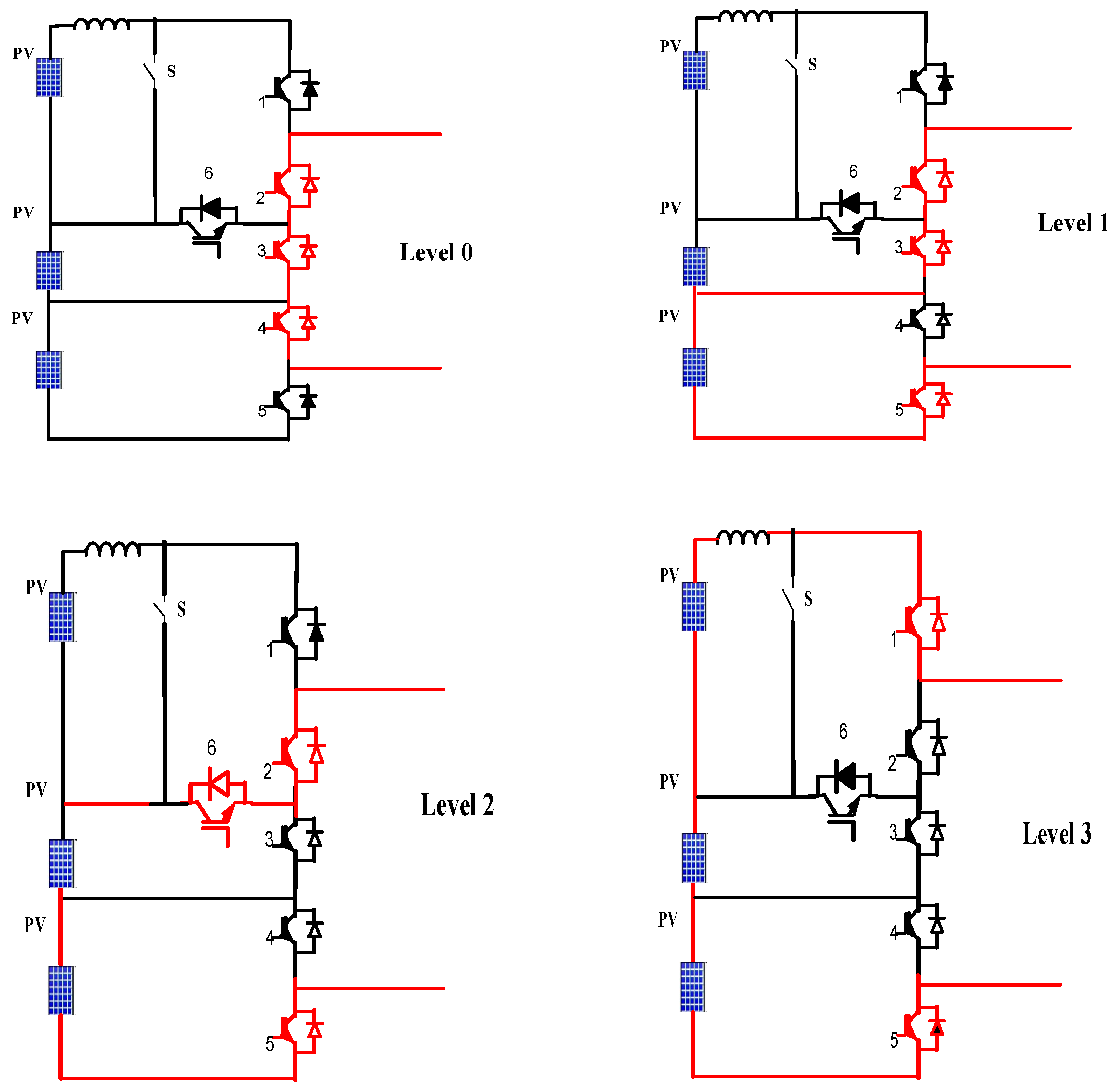
Figure 7.
Generated reference waveform using 60-degree PWM.
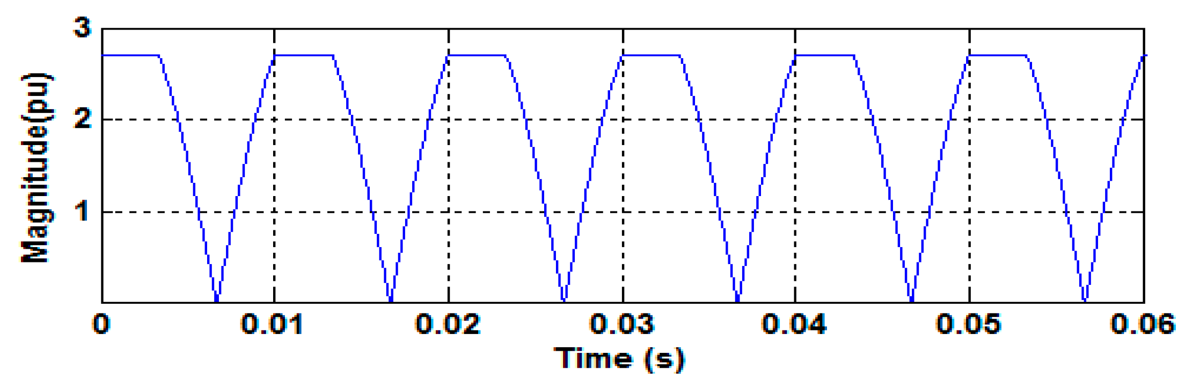
Figure 8.
(a) Output voltage waveform of RVTMLI, and (b) harmonic spectrum analysis of RVTMLI output voltage.
Figure 8.
(a) Output voltage waveform of RVTMLI, and (b) harmonic spectrum analysis of RVTMLI output voltage.

Figure 9.
Basic filter topologies: (a) L filter, (b) LC filter and (c) LCL filter.

Figure 10.
Topology of LCL filter.
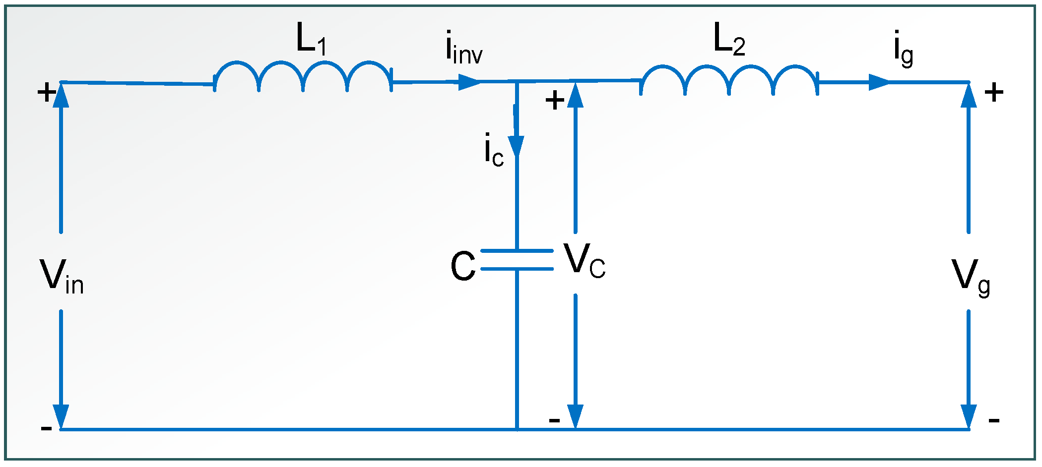
Figure 11.
Bode plot of grid connected LCL filter.
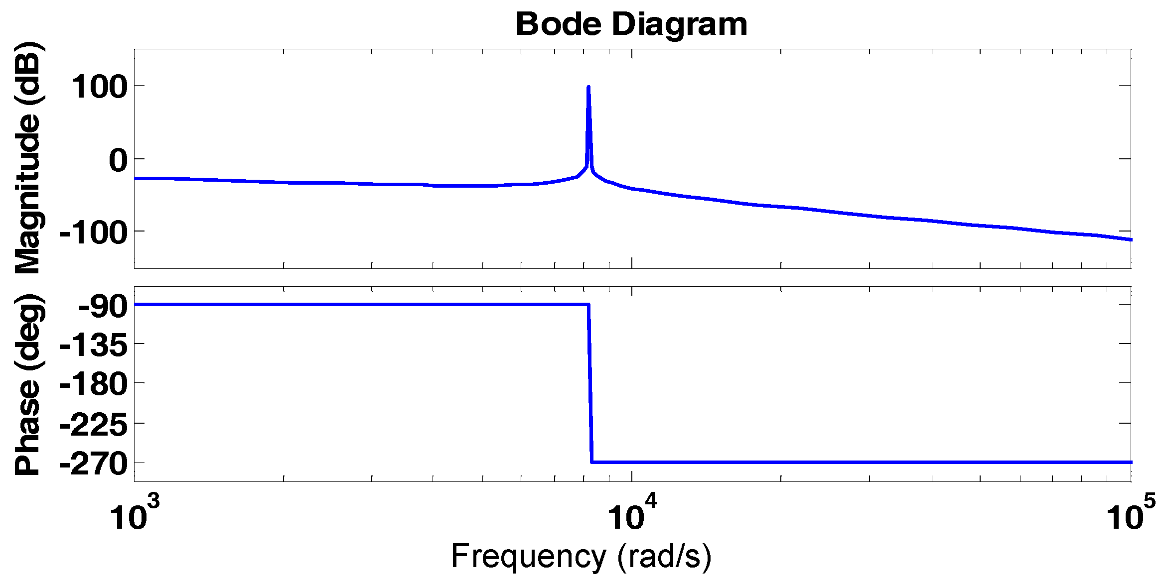
Figure 12.
Block Diagram of two degrees of freedom controller.
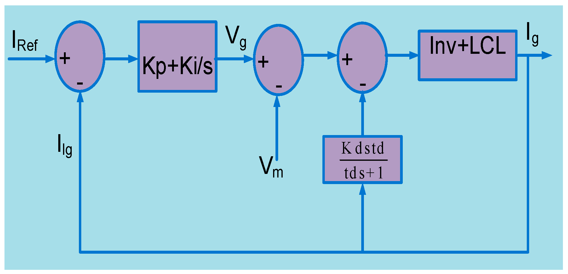
Figure 13.
Bode plot for PI-D control of grid connected inverter with LCL filter.
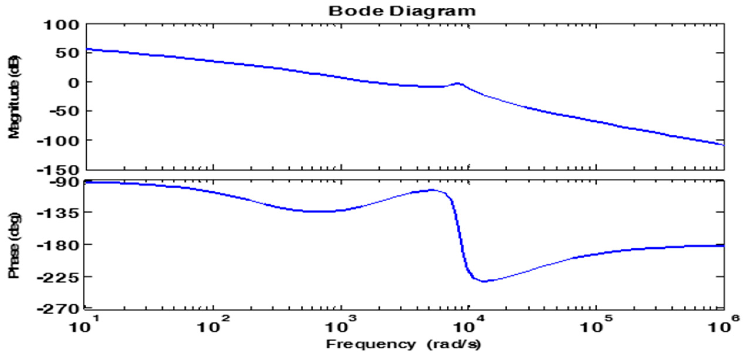
Figure 14.
(a) Block diagram of grid injected feedback current controller. (b) Bode plot for grid injected current feedback controller with LCL filter.
Figure 14.
(a) Block diagram of grid injected feedback current controller. (b) Bode plot for grid injected current feedback controller with LCL filter.
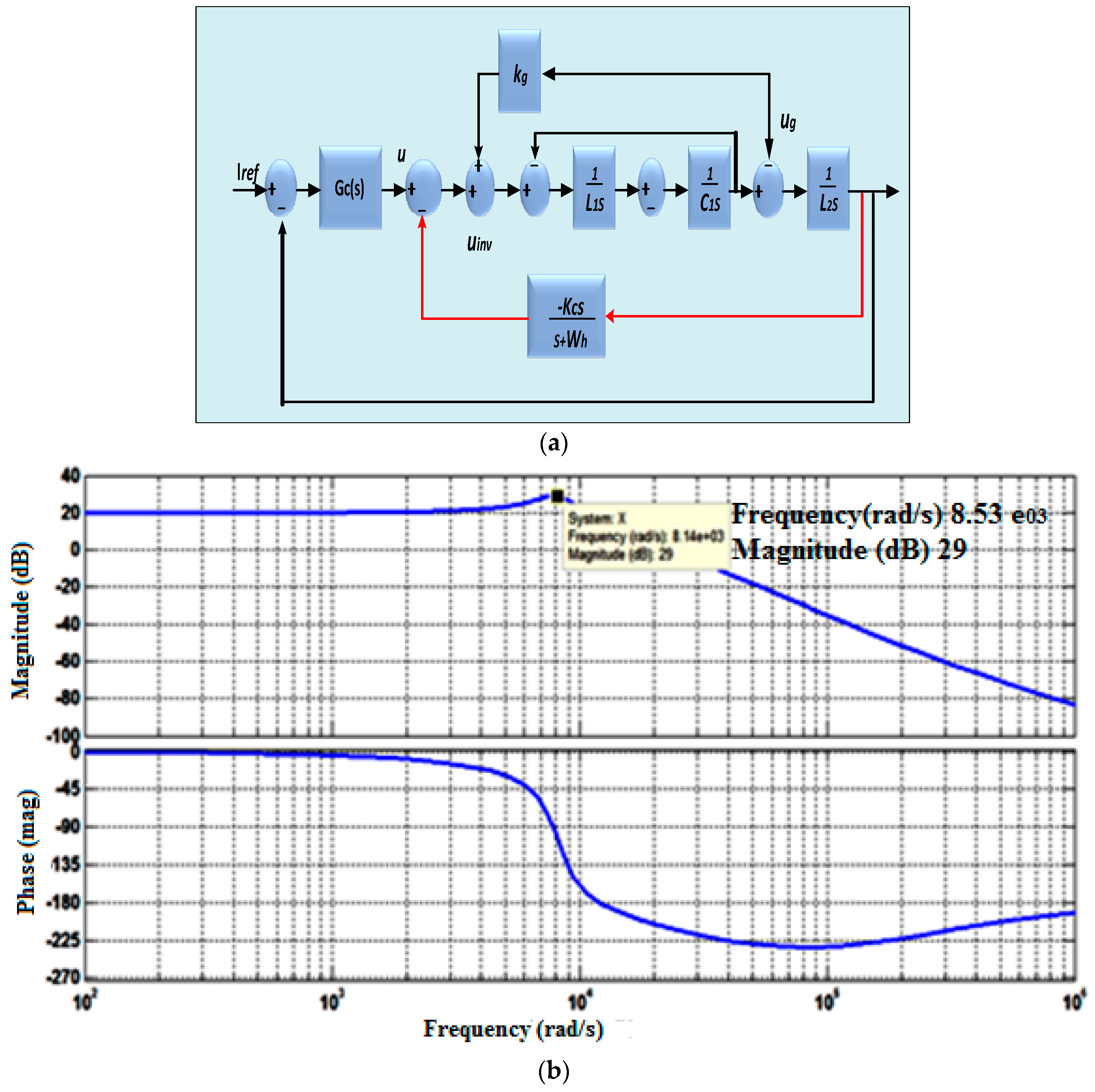
Figure 15.
Bode plot for feedback current controller with LCL filter.
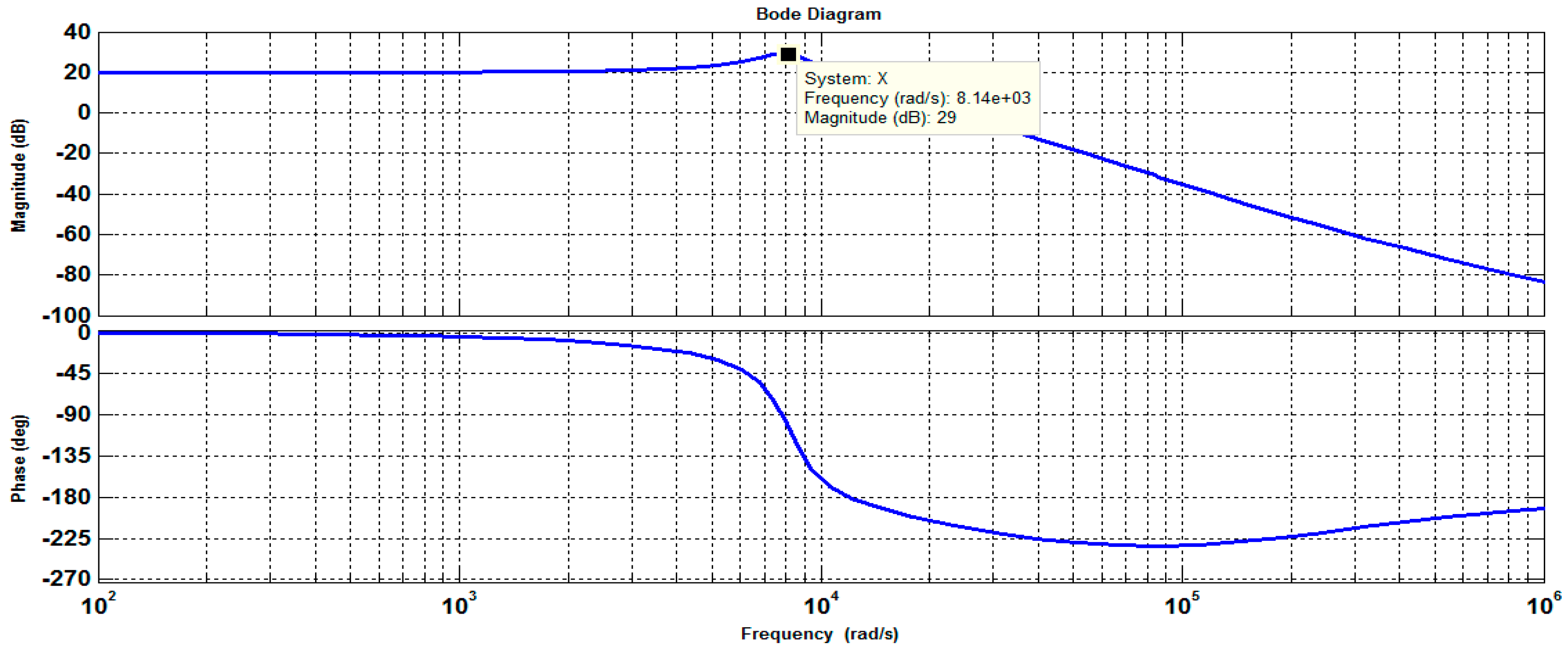
Figure 16.
Block diagram of PR-D controller.
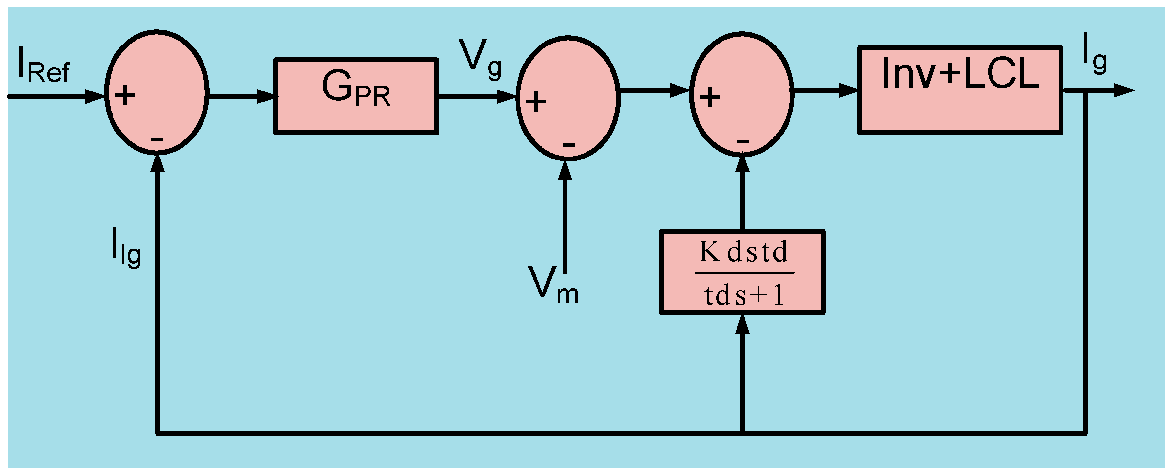
Figure 17.
Grid output voltage harmonic profile.

Figure 18.
Grid injected current harmonic profile.

Figure 19.
Bode plot for PR-D control of grid connected inverter by LCL filter.
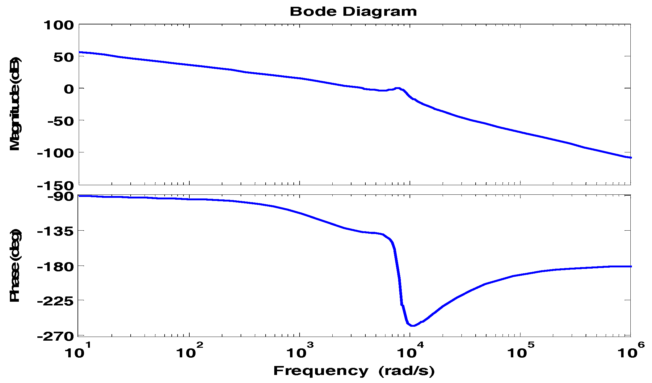
Figure 20.
(a) Hardware output of MLI unit and (b) Hardware prototype setup.


Table 1.
Parameters for LCL filter design.
| Inverter side inductance, L1 | 17.67 mH |
| Grid side inductance, L2 | 5.7 mH |
| Filter capacitor, C | 10 µF |
| Damping Resistor, Rd | 11.3 ohm |
© 2018 by the authors. Licensee MDPI, Basel, Switzerland. This article is an open access article distributed under the terms and conditions of the Creative Commons Attribution (CC BY) license (http://creativecommons.org/licenses/by/4.0/).
Share and Cite
MDPI and ACS Style
Oruganti, H.; Dash, S.S.; Nallaperumal, C.; Ramasamy, S. A Proportional Resonant Controller for Suppressing Resonance in Grid Tied Multilevel Inverter. Energies 2018, 11, 1024. https://doi.org/10.3390/en11051024
AMA Style
Oruganti H, Dash SS, Nallaperumal C, Ramasamy S. A Proportional Resonant Controller for Suppressing Resonance in Grid Tied Multilevel Inverter. Energies. 2018; 11(5):1024. https://doi.org/10.3390/en11051024
Chicago/Turabian StyleOruganti, Hemakesavulu, Subranshu Sekhar Dash, Chellammal Nallaperumal, and Sridhar Ramasamy. 2018. "A Proportional Resonant Controller for Suppressing Resonance in Grid Tied Multilevel Inverter" Energies 11, no. 5: 1024. https://doi.org/10.3390/en11051024
Note that from the first issue of 2016, this journal uses article numbers instead of page numbers. See further details here.