Comparison of the Energy Conversion Efficiency of a Solar Chimney and a Solar PV-Powered Fan for Ventilation Applications


1
Sustainable Process Integration Laboratory—SPIL, NETME Centre, Brno University of Technology, Brno 61669, Czech Republic
2
Energy Institute, Faculty of Mechanical Engineering, Brno University of Technology, Brno 61669, Czech Republic
*
Author to whom correspondence should be addressed.
Energies 2018, 11(4), 912; https://doi.org/10.3390/en11040912
Submission received: 16 February 2018
/
Revised: 4 April 2018
/
Accepted: 8 April 2018
/
Published: 12 April 2018
(This article belongs to the Special Issue Selected Papers from SDEWES 2017: The 12th Conference on Sustainable Development of Energy, Water and Environment Systems)
Abstract
:A study into the performance of a solar chimney and a solar photovoltaic (PV)-powered fan for ventilation applications was carried out using numerical simulations. The performance of the solar chimney was compared with that of a direct current (DC) fan powered by a solar PV panel. The comparison was carried out using the same area of the irradiated surface—the area of the solar absorber plate in the case of the solar chimney and the area of the solar panel in the case of the photovoltaic-powered fan. The two studied cases were compared under various solar radiation intensities of incident solar radiation. The results indicate that the PV-powered fans significantly outperform solar chimneys in terms of converting solar energy into the kinetic energy of air motion. Moreover, ventilation with PV-powered fans offers more flexibility in the arrangement of the ventilation system and also better control of the air flow rates in the case of battery storage.
1. Introduction
The stack effect induced by solar radiation can be employed for various purposes, including building ventilation. Interest in solar-driven ventilation in general and solar chimneys in particular has risen in the last two decades as utilization of renewable energy sources has become one of the main approaches to reducing the carbon footprint. A solar chimney (sometimes also called a solar stack or a solar updraft tower) is a device that converts the thermal energy of solar radiation into the kinetic energy of air motion. The interest in the utilization of solar chimneys has significantly increased over the last three decades, as can be seen from the number of publications on this topic.
Another area of solar energy utilization that has experienced significant development in the last several decades is solar photovoltaics. The decreasing prices of photovoltaic (PV) panels and developments in the area of direct current (DC) motors have brought about an alternative option for solar ventilation—fans powered by solar photovoltaics. Similar to solar chimneys, PV-powered fans do not require access to the power grid. The aim of the theoretical study presented in this paper was to compare the performance of a solar chimney with the performance of a DC fan powered by solar photovoltaics. A research question to be answered in this study can be formulated as follows: From an energy conversion point of view, when the area of the solar absorber plate of the chimney is the same as the area of the PV panel, is it more efficient to use the solar chimney or a DC fan powered by a PV panel? Computer models of both systems were implemented in MATLAB in order to perform simulations and make a comparison.
1.1. Solar Chimneys
The conversion of solar heat into air motion by means of solar chimneys can be used not only for building ventilation but also for power generation. One analysis of solar chimney efficiency was presented by Mullett et al. [1]. The author considered a solar chimney for power generation consisting of a horizontal solar collector and a vertical tower (chimney) with a uniform circular cross-section. The author used a simplified approach to address the overall efficiency of the system. In terms of the overall efficiency, the efficiency of conversion of solar radiation into thermal energy, the efficiency of conversion of thermal energy into air motion, and the efficiency of conversion of air motion into the shaft power of the turbine were taken into account. The overall efficiency was less than 1 percent for most of the investigated cases.
Suárez-López et al. [2] built a comprehensive three-dimensional (3D) CFD model of a solar chimney, validated by means of experimental data from the literature. The model was used for the investigation of the conditions in the solar chimney (such as the fluid flow patterns and the temperature distribution), and for the identification of parameters that directly influence the exergetic efficiency. The authors reported that their numerical results indicated a small efficiency in case of solar chimneys used for natural ventilation systems. The thermal exergetic efficiency for the studied case was 0.55%, and the useful exergetic efficiency was 0.0006%. The improved performance of the chimney was shown by the minimization of fluid dynamic losses, optimization of the channel geometry, and by the reduction of losses through the glass cover. Naraghi and Blanchard [3] developed a mathematical model of a solar chimney for the dynamic analysis. The model was based on the implicit finite differences applied to the energy balance equations for components of the solar chimneys. The Newton–Raphson numerical method was used for the solution of the discretized equations in time and a clear sky model was utilized for the determination of solar irradiance. A parametric study into the performance of a solar chimney was carried out. The authors reported that solar chimneys with a relatively large thermal mass can provide a reasonable airflow during the night and early morning with no solar irradiance. A high thermal mass of the absorbing plate also helped to reduce fluctuations of the airflow rate.
A numerical model of an inclined solar chimney was presented by Imran et al. [4]. The model solved two-dimensional (2D) steady-state turbulent flow induced by natural convection, and its functionality was validated with experimental data. The model was implemented in FORTRAN with the use of the finite volume method. The authors reported that the optimum inclination angle was 60, providing an about 20% higher rate of ventilation. The results indicated that the flow rate between 50 m/h and 425 m/h could be achieved for solar irradiation between 150 W/m and 750 W/m, corresponding to between 4 and 35 air changes per hour for a room with a volume of 12 m. An analytical iterative model of the airflow in solar chimneys based on the thermal boundary layer was reported by He et al. [5]. The model takes into account the spatial variation of the density which is ignored in most solar chimney models. The model is based on energy balance equations and the theory of thermal boundary layers. The author stated that their model outperformed existing analytical models in terms of the predicted airflow rates, and it allowed for the identification of the optimal chimney gap that would provide maximum air flow rate.
Sudprasert et al. [6] numerically investigated the influence of moist air on the solar chimney performance. An ANSYS Fluent model of heat transfer and fluid flow was assembled for the investigation of the chimney operation with dry and moist air (humidity between 30–80%). The authors reported that the airflow rate with the moist air was about 15–25% lower and the air temperature was higher than in case of the dry air. The authors recommended that the optimal aspect ratio should be about 14:1, with a limited opening height for the maximization of ventilation. An empirical model for solar chimneys assembled on the basis of experimental data acquired from the literature for various test rigs and configurations of solar chimneys was presented by Shi et al. [7]. The relationship between the airflow rate, cavity height and width, and solar radiation was derived. The model was then used in a parametric analysis addressing the various parameters of the solar chimneys. Saleem et al. [8] developed a mathematical model for the solar chimney which was based on the overall energy balances. The model was used for the determination of optimum parameters for a specified set of conditions. Further, the authors assembled a CFD model of the solar chimney which included the solution of the k-omega turbulence model for the fluid flow applied to the solution of the mass and energy equations. A good agreement between the simple model and the CFD model was reported which, in the authors’ opinion, justified the use of the simple model in optimization processes.
1.2. Solar-Powered Electric Motors
The application of solar photovoltaics in ventilation is not as widely addressed in the literature as the application of solar chimneys. Nonetheless, several authors have addressed the connection between PV cells and the electric motors. Badescu [9] developed a mathematical model for the system, including photovoltaic cells, an electric battery, an electric motor, and a water pump. The system was proposed for water storage instead of direct storage of electrical energy. The model of the system, developed in FORTRAN, consisted of a set of ordinary differential equations with the time derivative, and it allowed for the time-dependent simulations under various conditions. A submodel for the meteorological and actinometric data was implemented. The author presented a parametric analysis carried out with the use of the model for two modes of PV cell operation. At sufficient solar irradiance, the PV cells supplied electricity to both the battery and the motor. At insufficient solar irradiance the motor was powered from the battery.
Atlam and Kolhe [10] developed a mathematical model of the solar PV-powered direct current permanent magnet motor–propeller system. They used the model for the selection of a proper type of the motor and its parameters. The model developed using MATLAB/Simulink consisted of a set of algebraic equations and it allowed for steady-state simulations. The authors observed that a properly selected motor had operating points that closely matched the maximum power points of the PV array. The authors pointed out that the motor and its parameters had to be selected specifically according to a particular application. Gupta et al. [11] investigated a stand-alone system of the PV array and batteries powering a refrigerator. The authors assembled a computer model in the TRNSYS simulation tool and they validated the model with experimental data. Standard TRNSYS components were utilized for the PV panel, battery, inverter, and refrigerator. The model was then used in a parametric study with the aim to properly design the optimal parameters of the PV cells, batteries and of the insulation level of the refrigerator. The authors concluded that a refrigerator with an insulation layer of 50 mm thickness can feasibly be operated by means of a 200 W photovoltaic array coupled with a battery with a capacity of 50 Ah. The authors reported that such a configuration enables the stand-alone operation of the refrigerator over two cloudy days.
1.3. Scope of the Study
Solar chimneys are often proposed as an energy efficient way of building ventilation (see e.g., [12,13,14]). However, studies providing an analysis of energy performance of a solar chimney and its comparison to other ways of solar energy utilization in building ventilation are rarely found. With the decreasing prices of photovoltaic solar panels and advancements in the design of direct current motors for ventilation fans, there appears to be a more efficient, more flexible, and probably also cheaper option for building ventilation in comparison to solar chimneys.
The present study deals with the comparison of the energy conversion efficiency of a solar chimney and a PV-powered fan. In case of the solar chimney, a theoretical case, non-achievable in real life, was considered. The models of the PV panel and the DC fan were based on the data provided by manufacturers. The accuracy of the model in this case was assessed by comparison of the results with the data from the fan manufacturer. Though the conducted study is rather simple, the comparison of a solar chimney to a ventilation fan powered by solar photovoltaics (as far as we know) has not been published yet.
The main focus of the study was to assess how effective a solar chimney was in building ventilation in comparison to a fan powered by a solar PV panel. The solar chimneys are typically used for air exhaust and thus the thermal energy contained in the air is not utilized in the building. The solar chimneys basically substitute air exhaust fans as the drivers for air movement. The energy efficiency was therefore expressed in terms of conversion of the incident solar radiation to the kinetic energy of air motion.
2. Solar Chimney Scenario
There are many possible designs of solar chimneys. The solar chimneys intended for power generation usually consist of a vertical tower (tube) and a horizontal solar collector. The power-generating turbines are usually located at the base of the tower. Thermal storage in the ground under the solar collector or other forms of thermal storage mass can extend the operation of the solar chimney power plants to night-time hours. The solar chimneys used for ventilation are usually rectangular cavities with the glass cover on one side of the cavity and the solar absorber plate on the other side. The chimney can either be vertical or inclined (for better irradiation). This design of the solar chimney, which is very similar to to that of a solar collector, was considered in the present study.
The calculation of the airflow rate through the solar chimney can be rather complex depending on the level of details that are taken into account. Solar radiation-induced buoyancy is not the only driving force for airflow in solar chimneys. The effect of wind in this respect can be significant and under certain circumstance it can become a dominant driving force. Also, in the case of solar chimneys installed in buildings, the buoyancy force due to the difference between the indoor and outdoor air temperature can very much influence the air flow rate through the solar chimney. Neither the effect of wind nor the influence of the temperature difference between the indoors and outdoors was considered in the present study. These influences are also present when a fan powered by photovoltaics is used. The aim of the study was to compare solar-driven air flow in the case of two forms of exploitation of solar energy and not to investigate the complex performance of a solar chimney or a PV-powered fan for a particular installation.
3. Computer Model of Solar Chimney
3.1. Basic Considerations and Governing Equations
A simple iterative model for a solar chimney was derived and implemented in MATLAB. A chimney in the form of the rectangular glass-covered cavity, as shown in Figure 1, was considered. An idealized theoretical case was considered in the study. Only the optical loss (transmittance and absorptance) was taken into account in case of the solar chimney. The heat loss of the solar chimney to the ambient environment was neglected. The friction and local losses for the air flow in the solar chimney were also neglected. It would be relatively easy to account for transmission and radiation heat loss in the solar chimney model, but the heat loss depends on the actual materials used in the design of the chimney. As the aim of the study was to compare the principles of solar energy utilization for ventilation rather than comparing the actual designs, the neglect of the heat loss seemed justifiable.
The solar radiation incident on the solar chimney warms up the air in the chimney cavity and the induced buoyancy force causes the air movement in the cavity. Solar heat (thermal energy) is thus converted into air motion (kinetic energy of air). It was assumed that the solar radiation absorbed by the solar absorber plate was entirely transferred to the air in the cavity of the solar chimney. The energy balance of the air passing through the solar chimney is then
where is the intensity of solar radiation incident on the glazing of the chimney, is the area of the glazing, is the transmissivity of the glazing, is the absorptivity of the solar absorber plate, is the mass flow rate through the chimney, is the specific heat of the air at a constant pressure, and are the inlet and outlet air temperatures, respectively, is the the cross-section area of the chimney, and and are the mean density and velocity of the air in the chimney, respectively. The stack effect in the solar chimney can be expressed as
where g is the standard gravity, h is the height of the chimney, is the density of the ambient air, K is overall resistance coefficient, f is the friction factor, D is the equivalent diameter, represents local loss coefficients, and is the inlet air velocity to the chimney. The case with corresponds to the situation without both the local losses and the friction loss. Since the mass flow rate of the air depended on the buoyancy force and the buoyancy force induced by the difference of densities and is dependent on the mass flow rate, the solution of the model for the solar chimney is performed iteratively in a loop until a balance between the two mentioned terms is achieved. The values of the parameters and inputs to the computer model of the solar chimney are summarized in Table 1.
3.2. Numerical Discretization
A one-dimensional (1D) discretization of the solar chimney was considered. A schematic of the discretization is shown in Figure 1. The solar chimney was vertically divided into n segments in the direction of the air flow. The heat flux transferred from the solar radiation into the air is
where is the area of glazing in the i-th section. The mass flow rate of the air through the chimney can be determined from the parameters of the air at the inlet as
The temperature of the air in the -th section is then given as
where is the temperature of the air in the i-th section. The mean temperature of the air in the solar chimney is the mean of the temperatures . The inlet air velocity to the chimney is determined as
and the pressure difference in the solar chimney induced by the buoyancy was calculated as
4. Scenario with the Fan Powered by Solar PV
The simulated scenario with the direct current (DC) fan powered by solar PV was similar to the scenario with the solar chimney. A solar panel with the same area as the area of the solar chimney absorber plate was considered. A DC fan was assumed to be connected to a PV panel through a control unit without battery energy storage. The control unit of the fan was not modeled in detail. It was only assumed that the control unit would prevent damage of the fan when the solar panel provided more power than the fan could handle. The fan air flow rates were calculated for a range of incident solar radiation intensities with the use of the parameters of the solar panel and the characteristics of the DC fan. As mentioned earlier, the goal of the study was to compare two ways of converting solar energy into air motion rather than comparing a particular design of a solar chimney to a particular configuration of a PV-powered fan. Nonetheless, the parameters of both the solar panel and the DC fan were adopted from data sheets of real product in order to consider a realistic performance of these devices in the study.
4.1. Solar Panel
A solar panel with the area of 1.3 m was considered in the study. The panel had the maximum power of 210 W, its maximum power current was 5.1 A, its maximum power voltage was 41.3 V, and the open circuit voltage was 50.9 V. The short circuit current of the solar panel was 5.57 A, the temperature coefficient of the open-circuit voltage in the standard test conditions (STCs) was V/C, and the short-circuit current in STC was 0.00167 A/C.
4.2. DC Fan
An axial DC fan with the operation voltage between 30 V and 57 V was considered in the study. The maximum speed of the fan was 5300 rpm, corresponding to a maximum power of 66 W, a maximum flow rate of 10 m/min, and a maximum pressure of 410 Pa. The I-V characteristic slope of 0.017 A/V and the -V characteristic slope of 83.3 rpm/V were considered. The pressure difference-air flow rate (-Q) curves from a data sheet were approximated with the use of exponential functions with the -value of 0.9993. The -Q relationships of the fan are shown in Figure 2 for various speeds of the fan. Similar to the solar chimney scenario, the pressure loss of the connected ventilation ductwork was not considered and thus the fan operated at the maximum flow rate for the supply voltage.
5. Computer Model of the PV Panel with the DC Fan
Two separate models for the PV panel and for the DC fan were implemented in MATLAB. The models were coupled together by means of the I-V characteristics of the PV panel and the I-V and -V characteristics of the electric motor of the fan. This approach was already verified by other investigators (see e.g., the work by Odeh et al. [15]).
5.1. Model of PV Panels
Though some simple models of PV panels can be utilized, a more detailed model proposed by Sera et al. [16] was adopted in the simulations. The implemented model of the PV panel is based on an electric circuit of a photovoltaic cell using the single exponential model. The performance of the PV panel is given by its current–voltage (I-V) characteristics
where is the photo-generated current in STC, is the dark saturation current in STC, is the panel series resistance, is the panel shunt resistance, A is the ideality factor, k is the Boltzmann constant, q is the charge of the electron, is the number of cells in the panel connected in a series, and is the temperature of the cell in STC. The I-V characteristics has to be calculated iteratively since Equation (8) is implicit for the electric current. The quantities and are determined according to incident solar irradiation, cell temperature, and datasheet parameters of the PV panel. Since the paper is not concerned with the detailed description of the adopted model of the PV panel, the reader is referred to [16] for further details. A typical output of the model in the form of the current-voltage I-V (solid lines) and power-voltage P-V (dashed lines) characteristics is shown in Figure 3. Figure 4 demonstrates the dependence of the current-voltage ratio for various values of the cell temperatures of the PV panel. The results in Figure 3 and Figure 4 were calculated for the PV panel defined in the foregoing section. The system consisting of such a PV panel coupled with a DC fan is considered below in the comparison between the solar chimney and the PV panel–fan system.
5.2. Model of the DC Fan
The current-voltage (I-V) and speed-voltage (-V) characteristics of the DC fan can be considered as linear and they can be used for the determination of the speed of the fan with the assumption that those are valid for a constant torque [17]. Such assumption was already used by other investigators (see e.g., [15]). The I-V characteristics of the PV panel and of the DC fan are therefore solved simultaneously and the intersection of the two I-V characteristics determines the actual current and voltage transferred from the PV panel to the fan. The speed of the fan is then determined from the -V characteristics. The performance of the fan is defined by its -Q relationship (see Figure 2). Such dependence, usually provided by the manufacturer, is given for a defined speed, air pressure, and temperature. The air flow rate Q for the actual speed of the fan determined from the -V characteristics for actual air pressure p and air temperature T was calculated by means of the affine relationship [15]
where , , , and are the reference flow rate, the reference speed of the fan, the reference air pressure, and the reference air temperature, respectively.
6. Comparison of Performance and Discussion
The performance of the solar chimney and the PV-powered fan was compared in terms of the achieved air flow rates and energy conversion efficiencies. As shown before, the simplified model of the solar chimney neglected many factors that would decrease the air flow rate through the chimney in real life operation (heat loss, friction loss, constraints on heat transfer between the solar absorber plate and the passing air).
6.1. Mass Flow Rates
Figure 5 shows the simulation results for the air mass flow rate through the solar chimney for various heights of the chimney, denoted h in Figure 1 and Figure 5. The width of the chimney, denoted b, was determined in such a way that the area of the chimney was the same as the area of the solar panel (1.3 m). The depth of the chimney, denoted B in Figure 1, was constant and equal to 0.2 m in all cases. The transmissivity values of the glass and the absorptivity of the solar absorber plate were set to 0.91 and 0.95, respectively. As can be seen seen in Figure 5 the air mass flow rate decreases with the increasing height of the chimney. As the irradiated area of the solar chimney and the chimney gap remain the same, the cross-section area of the chimney cavity decreases with the increasing height of the chimney. As a result, higher velocity is needed for the same air flow rate.
Figure 6 presents the simulation results for the mass flow rate through the DC fan powered by the PV panel. The characteristics of the PV panel and the DC fan have been described in detail in the foregoing sections. The ideality factor of the PV panel was set to 1.5 and the series resistance of the cells in the PV panel of 0.004 was considered. The results are shown for various temperatures of the PV panel ().
The comparison of the results depicted in Figure 5 and Figure 6 indicates that the DC fan powered by a solar panel provides higher mass flow rates of air than the solar chimney with the same irradiated area. The air mass flow rate of the fan is almost constant for radiation intensity above 400 W/m. The reason for this is the power input of the fan. The fan has the maximum power input of 66 W while the solar panel provides almost 200 W at a solar radiation intensity of 1000 W/m (as can be seen in Figure 3) and thus it would be able to power three fans at that level of irradiation. For the solar radiation intensity below 200 W/m the air mass flow rate falls sharply as the solar panel does not provide enough power for the nominal performance of the fan.
The accuracy of the model of the DC fan was assessed by the comparison of the flow rates obtained from Equation (9) (Figure 6) and the data from the fan manufacturer shown in Figure 2. The density of air entering the fan was considered constant and equal to 1.19 kg/m. The pressure drop of the connected ductwork was neglected and as a result in Equation (9). The fan speed depended on the current and voltage of the PV panel, as explained in Section 4.2. It was thus possible to compare the flow rate obtained from Equation (9) for a certain fan speed with the flow rate for the same fan speed from the data of the fan manufacturer. The difference between the flow rates was less than 1% in the entire range of the flow rates.
6.2. Energy Conversion Efficiency
Since the pressure drop of the connected ductwork was not considered in the study, the energy conversion efficiency can be expressed as the ratio between the kinetic energy of the moving air and the total solar radiation incident on the area of the solar chimney and the solar panel, respectively. The air mass flow rates were already presented in the previous section. The kinetic energy of the air flowing through the chimney and through the fan can be obtained as
where and w are the mass flow rate and the mean air velocity, respectively. The energy conversion efficiency can then be expressed as follows
where is the solar radiation incident on the area S of the solar chimney or the PV panel.
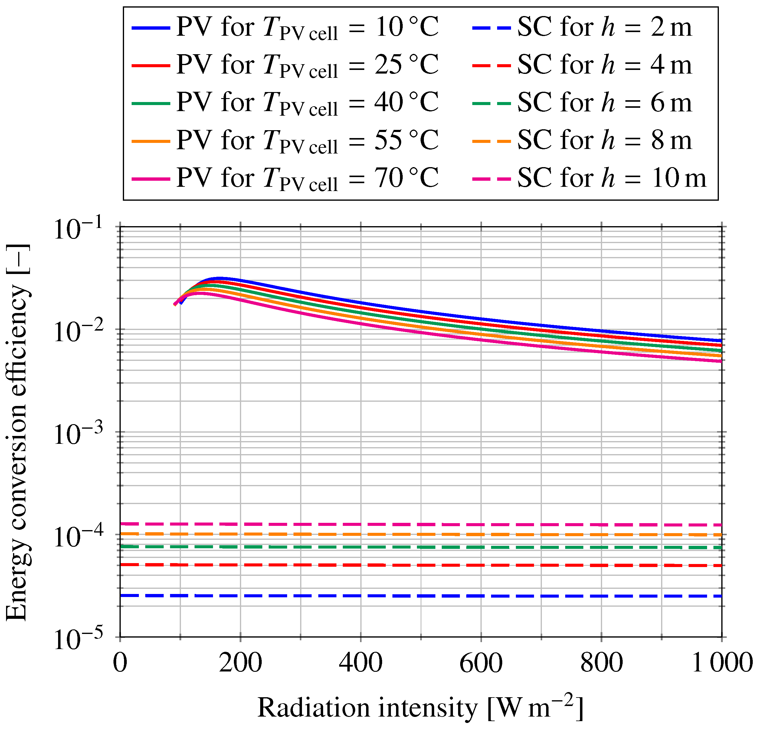
Figure 7 shows the energy conversion efficiency for the solar chimney (denoted as SC) and the PV-powered fan (denoted as PV) depending on the radiation intensity. The energy conversion efficiency for several temperatures of the PV panel and several heights of the solar chimney are plotted in Figure 7. Note that the logarithmic scale for the energy conversion efficiency is used in Figure 7. As can be seen, the energy conversion efficiency of a solar chimney is very small for all the considered heights. The value of the efficiency ranges between 0.0025% and 0.013% for the chimneys with heights of 2 m and 10 m, respectively. This is in agreement with conclusions of other investigators (see e.g., [1]). Moreover, the energy conversion efficiency for the solar chimney is virtually independent of the radiation intensity. This is due to the neglected heat loss and friction losses.
As for the PV-powered fan, the conversion efficiency is about two orders of magnitude higher than in the case of the solar chimney. As expected, the efficiency decreases with the increasing cell temperature of the PV panel since its efficiency decreases as well. Considering the cell temperature of the PV panel of 40 C, the total conversion efficiency peaks at approximately 2.7% for about 150 W/m of the radiation intensity. As the radiation intensity increases, the conversion efficiency decreases to about 0.8% for the radiation intensity of 800 W/m. The reason for such behavior is clear in Figure 6. The air mass flow rate of the fan does not increase very much for a radiation intensity above 400 W/m. As a result, the energy conversion efficiency decreases with increasing radiation intensity, as can be deduced from Equation (11). The main reason for low energy conversion efficiency at high radiation intensities is the maximum power input of the DC fan considered in the study, which was about 66 W. At a solar radiation intensity of 1000 W/m the solar panel would be able to power three considered DC fans and both the air mass flow rate and overall conversion efficiency would increase significantly. The reason for choosing a DC fan with much smaller power than the nominal output (at 1000 W/m) of the photovoltaic solar panel was the considered application in building ventilation. The DC fan considered in the study is able to provide a high air mass flow rate at a relatively small radiation intensity (from about 100 W/m). The performance curves of a more powerful fan would shift towards higher radiation intensities with a significant operation gap for small solar radiation intensities.
6.3. Economic Considerations
Both the solar chimney and the PV-powered fan can operate without access to the power grid. The potential cost savings of these two ways of exploiting solar energy are twofold; capital cost savings and operating cost savings. In situations where solar chimneys or PV-powered fans are used instead of grid-connected fans, the potential capital cost savings are related to the installation of the power supply for the grid-connected fans. These costs can be significant in case of retrofits of existing passive stack ventilation systems when the performance of the passive stack ventilation is to be extended by the use of a grid-connected fan. The installation of power supply for the fan mounted on top of an existing passive stack usually exceeds the cost of the fan itself. The project of the power supply installation needs to be prepared (usually by an electrical engineer), the power supply with safety features needs to be installed by an electrician, and the installation of power supply needs to be commissioned by an authorized specialist. The costs associated with the installation of power supply for a fan can reach several hundred euros. On the other hand, a solar chimney and a PV-powered fan in particular can often be installed on top of an existing passive stack with minimum additional costs.
The operating cost savings mainly depend on the electricity prices. The average price of electricity in 28 member states of the EU in the first half of 2017 was 0.204 EUR/kWh in case of household use and 0.114 EUR/kWh in case of non-household use [18]. The considered 66 W fan operating at full capacity 5 h a day would consume 120 kWh/year of electricity. The potential operating cost savings are thus 25 EUR/year (14 EUR/year in case of non-household use) assuming that maintenance costs are the same in case of grid-connected fan, solar PV-powered fan, and the solar chimney. Both the solar chimney and the PV-powered fan are intended to assist passive stack ventilation during unfavorable conditions (high outdoor temperature, low wind speed). These conditions depend very much on the climatic region, but the year-average of 5 h a day seems to be a safe figure in the case of Central Europe. As was shown, the operating cost savings are relatively small. Therefore, the total capital cost will be the main factor when deciding between the grid-connected fan and the solar chimney or the solar PV-powered fan. The PV-powered fan can be an attractive option in countries with high electricity prices and high capital costs for installation of power supply (high wages of involved specialists).
As far as the capital costs of the solar chimney and the solar PV-powered fan are concerned, the conducted study indicates that at the same ventilation capacity the PV-powered fan can be a less expensive option. The acquisition cost of the considered fan was about 90 EUR and the cost of the solar PV panel was about 520 EUR. The capital costs of PV-powered fans can decrease when compact units containing the fan, the solar panel, and the control unit are used. There already are some manufacturers of such units and more suppliers will likely emerge with the increasing demand.
Since the overall efficiency of the considered PV-powered fan was about two orders of magnitude higher than that of the considered solar chimney, the area of the solar chimney would need to be much larger to provide the same air flow rates (induced by solar irradiation). Solar chimneys are not consumer products; therefore, they need to be custom built for a given application. That significantly increases per-unit cost in comparison to mass market products such as DC fans and solar PV panels. The materials for the construction of solar chimneys are generally inexpensive. The retail price of ordinary clear glass usable as a glass cover can be less than 20 EUR/m. However, toughened or even safety glass may be required or recommended for most solar chimneys. The clear safety glass can cost more than 50 EUR/m. The frame of the chimney can be welded from metal profiles. The sheet metal can be used for solar absorber plate and also for external surfaces of the chimney. Thermal insulation (i.e., styrofoam, mineral wool, or polyurethane) that is needed in most climates contributes to both better energy efficiency and higher capital costs. The most expensive part of the capital cost is the cost of labor (manufacturing) and in some cases also the transportation and installation costs. A crane may be needed to put the solar chimney on top of a building. Figure 8 shows an experimental solar chimney being installed on the roof of a demonstration house with hybrid ventilation on the campus of Brno University of Technology in November 2003. Unfortunately, in this case the solar chimney was the only part of the house installed by a crane, and the cost of renting a crane contributed significantly to the capital cost of the solar chimney.
7. Conclusions
A performance comparison between a solar chimney and a DC fan powered by solar photovoltaics was undertaken using various solar radiation intensities. Solar radiation was the only source of energy for the motion of air considered in the study. The results shown in Figure 5 and Figure 6 demonstrate that a PV-powered DC fan can provide up to three times higher air mass flow rates as compared to a solar chimney for the same solar incidence area (the area of solar absorber plate in the case of the solar chimney and the area of the PV panel in the case of the PV-powered fan). Many factors that would decrease the air mass flow rate through the solar chimney in real-life operation were not taken into account in the study. The results indicate that the fans powered by solar photovoltaics provide two orders of magnitude higher conversion efficiency of solar radiation to air motion as compared to solar chimneys. The difference in the efficiency will further increase as more efficient PV panels, DC motors, and fan impellers are developed.
PV-powered fans can be used for both air supply and air exhaust, while the use of solar chimneys is limited to air exhaust. Another advantage of a PV-powered fan is the much easier positioning of the solar panel in terms of the slope and azimuth in comparison to a solar chimney. Moreover, the electricity from the PV panels that is not immediately consumed by the fans can be stored in the batteries or it can be used for other purposes. A steady-state operation of the fan at constant irradiation was considered in the present study. Future work should focus on transient operation of the fan for the solar irradiation of a location and on the possibilities of flow rate control and electric storage.
Acknowledgments
This paper has been supported by the project Sustainable Process Integration Laboratory—SPIL, No. CZ.02.1.01/0.0/0.0/15_003/0000456, funded by European Research Development Fund, Czech Republic Operational Programme Research, Development and Education; Priority 1: Strengthening capacity for quality research.
Author Contributions
P.C. and L.K. conceived and designed the computer model for the solar chimney. L.K. and J.H. conceived and designed the computer model for the PV-powered fan. L.K. performed the computer simulations. L.K., P.C. and J.H. assessed and evaluated the computational results. L.K. and P.C. wrote the paper.
Conflicts of Interest
The authors declare no conflict of interest.
Nomenclature
| A | ideality factor |
| b | width |
| B | depth |
| specific heat at constant pressure | |
| D | equivalent diameter |
| f | friction factor |
| h | height |
| g | standard gravity |
| I | current |
| incident radiation | |
| k | Boltzmann constant |
| K | overall resistance coefficient |
| mass flow rate | |
| number of cells | |
| p | pressure |
| q | charge of electron |
| Q | volume flow rate |
| heat flux | |
| r | gas constant |
| R | electric resistance |
| area of glazing | |
| cross-section area of chimney | |
| T | temperature |
| V | voltage |
| w | air velocity |
| absorptivity | |
| local loss coefficient | |
| density | |
| transmissivity | |
| speed |
References
- Mullett, L.B. The solar chimney—Overall efficiency, design and performance. Int. J. Ambient Energy 1987, 8, 35–40. [Google Scholar] [CrossRef]
- Suárez-López, M.J.; Blanco-Marigorta, A.M.; Gutiérrez-Trashorras, A.J.; Pistono-Favero, J.; Blanco-Marigorta, E. Numerical simulation and exergetic analysis of building ventilation solar chimneys. Energy Convers. Manag. 2015, 96, 1–11. [Google Scholar] [CrossRef]
- Naraghi, M.H.; Blanchard, S. Twenty-four hour simulation of solar chimneys. Energy Build. 2015, 94, 218–226. [Google Scholar] [CrossRef]
- Imran, A.A.; Jalil, J.M.; Ahmed, S.T. Induced flow for ventilation and cooling by a solar chimney. Renew. Energy 2015, 78, 236–244. [Google Scholar] [CrossRef]
- He, G.; Zhang, J.; Hong, S. A new analytical model for airflow in solar chimneys based on thermal boundary layers. Sol. Energy 2016, 136, 614–621. [Google Scholar] [CrossRef]
- Sudprasert, S.; Chinsorranant, C.; Rattanadecho, P. Numerical study of vertical solar chimneys with moist air in a hot and humid climate. Int. J. Heat Mass Transf. 2016, 102, 645–656. [Google Scholar] [CrossRef]
- Shi, L.; Zhang, G.; Cheng, X.; Guo, Y.; Wang, J.; Chew, M.Y.L. Developing an empirical model for roof solar chimney based on experimental data from various test rigs. Build. Environ. 2016, 110, 115–128. [Google Scholar] [CrossRef]
- Saleem, A.A.; Bady, M.; Ookawara, S.; Abdel-Rahman, A.K. Achieving standard natural ventilation rate of dwellings in a hot-arid climate using solar chimney. Energy Build. 2016, 133, 360–370. [Google Scholar] [CrossRef]
- Badescu, V. Dynamic model of a complex system including PV cells, electric battery, electrical motor and water pump. Energy 2003, 28, 1165–1181. [Google Scholar] [CrossRef]
- Atlam, O.; Kolhe, M. Performance evaluation of directly photovoltaic powered DC PM (direct current permanent magnet) motor—Propeller thrust system. Energy 2013, 57, 692–698. [Google Scholar] [CrossRef]
- Gupta, B.L.; Bhatnagar, M.; Marhur, J. Optimum sizing of PV panel, battery capacity and insulation thickness for a photovoltaic operated domestic refrigerator. Sustain. Energy Technol. Assess. 2014, 7, 55–67. [Google Scholar] [CrossRef]
- Hosien, M.A.; Selim, S.M. Effects of the geometrical and operational parameters and alternative outer cover materials on the performance of solar chimney used for natural ventilation. Energy Build. 2017, 138, 355–367. [Google Scholar] [CrossRef]
- Lei, Y.; Zhang, Y.; Wang, F.; Wang, X. Enhancement of natural ventilation of a novel roof solar chimney with perforated absorber plate for building energy conservation. Appl. Therm. Eng. 2016, 107, 653–661. [Google Scholar] [CrossRef]
- Khanal, R.; Lei, C. An experimental investigation of an inclined passive wall solar chimney for natural ventilation. Sol. Energy 2014, 107, 461–474. [Google Scholar] [CrossRef]
- Odeh, N.; Grassie, T.; Henderson, D.; Muneer, T. Modelling of flow rate in a photovoltaic-driven roof slate-based solar ventilation air preheating system. Energy Convers. Manag. 2006, 47, 909–925. [Google Scholar] [CrossRef]
- Sera, D.; Teodorescu, R.; Rodriguez, P. PV panel model based on datasheet values. In Proceedings of the IEEE International Symposium on Industrial Electronics, Vigo, Spain, 4–7 June 2007; pp. 2392–2396. [Google Scholar] [CrossRef]
- Hadj Arab, A.; Chenlo, F.; Benghanem, M. Loss-of-load probability of photovoltaic water pumping systems. Sol. Energy 2004, 76, 713–723. [Google Scholar] [CrossRef]
- Eurostat—Statistics Explained, Electricity Price Statistics. Available online: http://ec.europa.eu/eurostat/statistics-explained/index.php/Electricity_price_statistics (accessed on 3 April 2018).
Figure 1.
Schematic of the solar chimney (left) and the numerical discretization (right).
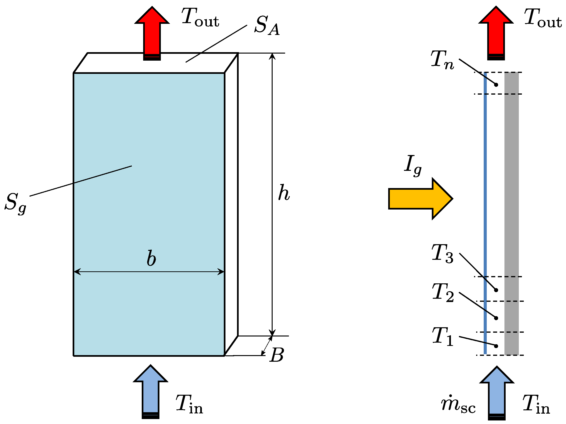
Figure 2.
-Q characteristics of the considered direct current (DC) fan for various speeds.

Figure 3.
I-V (solid lines) and P-V (dashed lines) characteristics of the considered photovoltaic (PV) panel for various solar irradiations and for a cell temperature of 30 C.
Figure 3.
I-V (solid lines) and P-V (dashed lines) characteristics of the considered photovoltaic (PV) panel for various solar irradiations and for a cell temperature of 30 C.

Figure 4.
I-V characteristics of the considered PV panel for various cell temperatures and for a solar irradiation of 400 W/m.
Figure 4.
I-V characteristics of the considered PV panel for various cell temperatures and for a solar irradiation of 400 W/m.

Figure 5.
Dependence of the mass flow rate through the solar chimney for various heights.

Figure 6.
Mass flow rate of the PV-powered fan for various solar cell temperatures.

Figure 7.
Energy conversion efficiency for the solar chimney and PV-powered fan.

Figure 8.
Installation of an experimental solar chimney on the roof of a demonstration house with a hybrid ventilation system.
Figure 8.
Installation of an experimental solar chimney on the roof of a demonstration house with a hybrid ventilation system.


Table 1.
Parameters and inputs to the model of the solar chimney.
| Parameter | Value | Description |
|---|---|---|
| 0.95 | absorptivity of the solar absorber plate | |
| B | 0.2 m | depth of the chimney cavity |
| 1005 J/kg·K | specific heat of air at constant pressure | |
| 1.19 kg/m | density of ambient (inlet) air | |
| 1.3 m | area of glazing | |
| 20 C | inlet air temperature | |
| 0.91 | transmissivity of glazing |
© 2018 by the authors. Licensee MDPI, Basel, Switzerland. This article is an open access article distributed under the terms and conditions of the Creative Commons Attribution (CC BY) license (http://creativecommons.org/licenses/by/4.0/).
Share and Cite
MDPI and ACS Style
Klimeš, L.; Charvát, P.; Hejčík, J. Comparison of the Energy Conversion Efficiency of a Solar Chimney and a Solar PV-Powered Fan for Ventilation Applications. Energies 2018, 11, 912. https://doi.org/10.3390/en11040912
AMA Style
Klimeš L, Charvát P, Hejčík J. Comparison of the Energy Conversion Efficiency of a Solar Chimney and a Solar PV-Powered Fan for Ventilation Applications. Energies. 2018; 11(4):912. https://doi.org/10.3390/en11040912
Chicago/Turabian StyleKlimeš, Lubomír, Pavel Charvát, and Jiří Hejčík. 2018. "Comparison of the Energy Conversion Efficiency of a Solar Chimney and a Solar PV-Powered Fan for Ventilation Applications" Energies 11, no. 4: 912. https://doi.org/10.3390/en11040912
Note that from the first issue of 2016, this journal uses article numbers instead of page numbers. See further details here.