Experimental Study on Horizontal Cylinders with Triangular Fins under Natural Convection

Department of Mechanical Engineering, Ajou University, Suwon 443-749, Korea
*
Author to whom correspondence should be addressed.
Energies 2018, 11(4), 836; https://doi.org/10.3390/en11040836
Submission received: 6 March 2018
/
Revised: 26 March 2018
/
Accepted: 28 March 2018
/
Published: 4 April 2018
Abstract
:In this study, thermal resistances of horizontal cylinders with triangular fins were measured in regard to fin numbers, fins heights, and temperature differences. Thereafter, an empirical correlation was proposed and validated for predicting the Nusselt numbers under the following conditions: Rayleigh number, 200,000–1,000,000; fin aspect ratio, 1.6–5.0; and fin number, 9–72. Finally, with the proposed correlation, the effects of fin numbers, fins heights, and fin thicknesses on the thermal resistances of the horizontal cylinders with triangular fins were investigated. It was shown that the thermal resistance generally increases as the fin number, fin height, and fin thickness increase. It is expected that horizontal cylinders for various cooling devices with triangular fins can be designed based on the findings of the present study.
1. Introduction
Because of the demands for more powerful and compact energy systems, current energy systems are experiencing a rapid increase in their heat loads [1,2]. As a result, cooling devices for energy systems have become essential, because system temperatures can become excessively high if heat is not dissipated through proper cooling devices. Additionally, high temperatures are detrimental to the performance and reliability of these systems. For example, in the case of light emitting diode (LED) lightings, the light outputs decrease with increasing diode temperatures, the light colors change undesirably at high temperatures, and diodes can deteriorate irreversibly at high temperatures [3,4,5,6,7]. Therefore, LED lightings also require appropriate cooling devices. Various cooling devices have been proposed, among which, extended surfaces under natural convection have been widely used [8,9]. This is because they are intrinsically robust and cost effective and, in particular, moving parts are not required for them.
Therefore, many extant studies have focused on extended surfaces under natural convection. In particular, as summarized in Table 1, there have been several research works on extended surfaces on horizontal cylinders [10,11,12,13,14,15,16,17]. Among them, cylinders with triangular extended surfaces have generally been used for cooling LED lightings because their shape is well matched with common LED bulbs. However, there are only a few studies on horizontal cylinders with triangular fins. Kwak et al. included results on horizontal cylinders with triangular fins when they investigated the effects of installation angles on thermal resistances of cylinders with triangular fins [17]. However, they did not focus on horizontal cylinders with triangular fins, and only one triangular-finned horizontal cylinder with a fixed height, fixed fin number, and fixed heat flux was experimentally investigated to validate their numerical model. Therefore, to the best of our knowledge, intensive experimental research work on horizontal cylinders with triangular plates has not been systematically conducted.
In this study, horizontal cylinders with triangular fins under natural convection were experimentally investigated by extending our recent research works on vertical cylinders with triangular fins [18,19]. The thermal resistances of the horizontal cylinders with triangular fins were measured in regard to fin numbers, fins heights, and temperature differences, Thereafter, an empirical correlation was proposed and validated to predict the Nusselt numbers under the following conditions: Rayleigh number, 200,000–1,000,000; fin aspect ratio, 1.6–5.0; and fin number, 9–72. Finally, with the proposed correlation, the effects of fin numbers, fins heights, and fin thicknesses on the thermal resistances of the horizontal cylinders with triangular fins were investigated.
2. Experimental Procedure
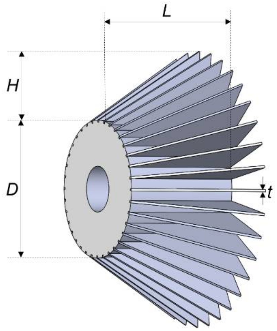
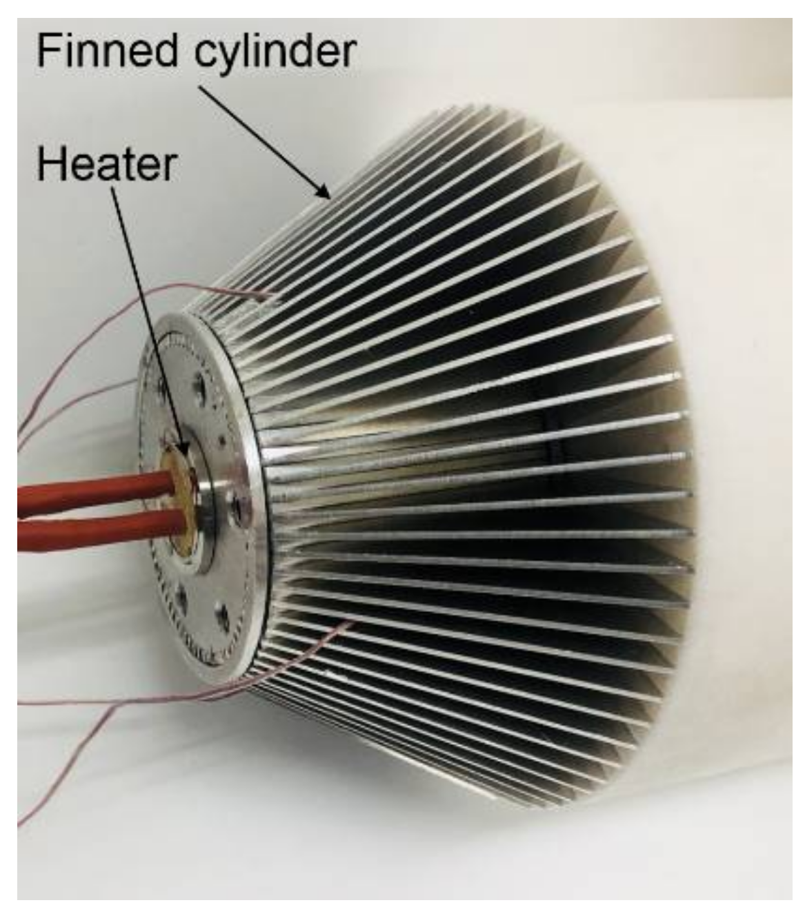
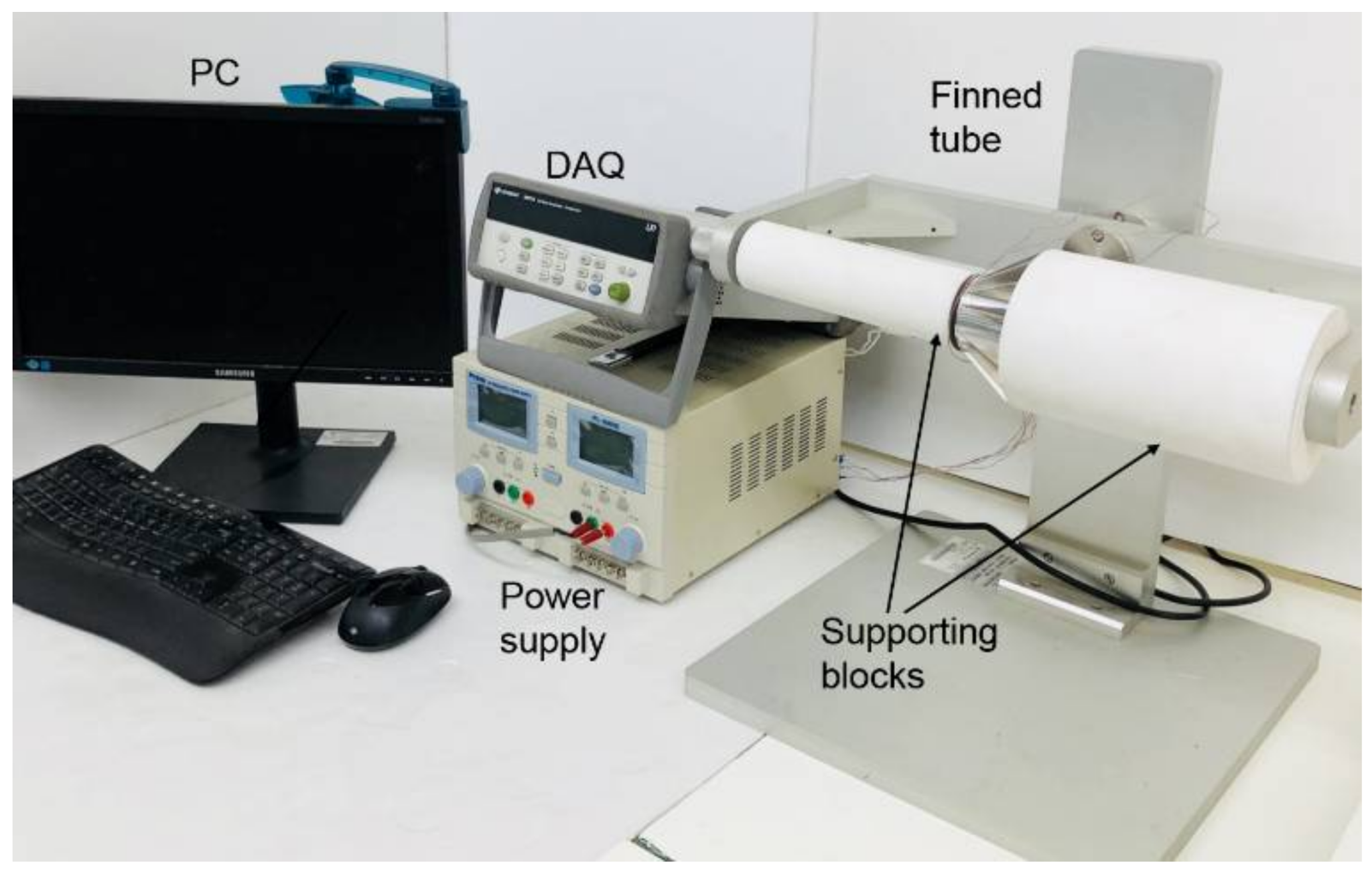
In this study, finned cylinders with three different fin heights and five different fin numbers were made and tested. The schematic diagram and the dimensions of the finned cylinders are shown in Figure 1 and Table 2, respectively. Large plates of aluminum 5052 alloy (ks = 138 W/(m K)) were cut into triangular fins by laser cutting. Thick tubes of aluminum 6061 alloy (ks = 167 W/(m K)), slits that could fit fins were made. Finned cylinders were then fabricated by interference fitting of the fins and the tubes (Figure 2). To measure the surface temperatures of the finned cylinders, T-type thermocouples were attached at four points around the cylinder. To heat the finned cylinders, a cartridge heater was inserted into the tubes. Thereafter, the finned cylinders with thermocouples and heaters were laid horizontally. The top and bottom sides of the finned cylinders were blocked using a long Teflon cylinder to minimize the heat dissipation through the top and bottom sides of each finned cylinder (Figure 3 and Figure 4). The finned cylinders were then heated by applying a constant power to the heater from a power supply (E3633A, Agilent Technologies, Santa Clara, CA, USA). The amount of power supplied varied from 1 W to 10 W. The thermocouples were connected to the data acquisition board (34970A, Agilent Technologies, Santa Clara, CA, USA) and received data on the surface temperatures of the heated finned tubes. The ambient air temperature was also measured. Experiments were conducted in a room without air flow. The finned cylinders were heated long enough to allow them to reach a steady state, and then the temperatures were measured. In addition, it was confirmed that the temperature change was less than 0.2 K for 3 min. After finishing the experiments, the uncertainty analysis was conducted (Appendix A). It was based on the uncertainty analysis presented in Lee et al. [18].
3. Results and Discussion
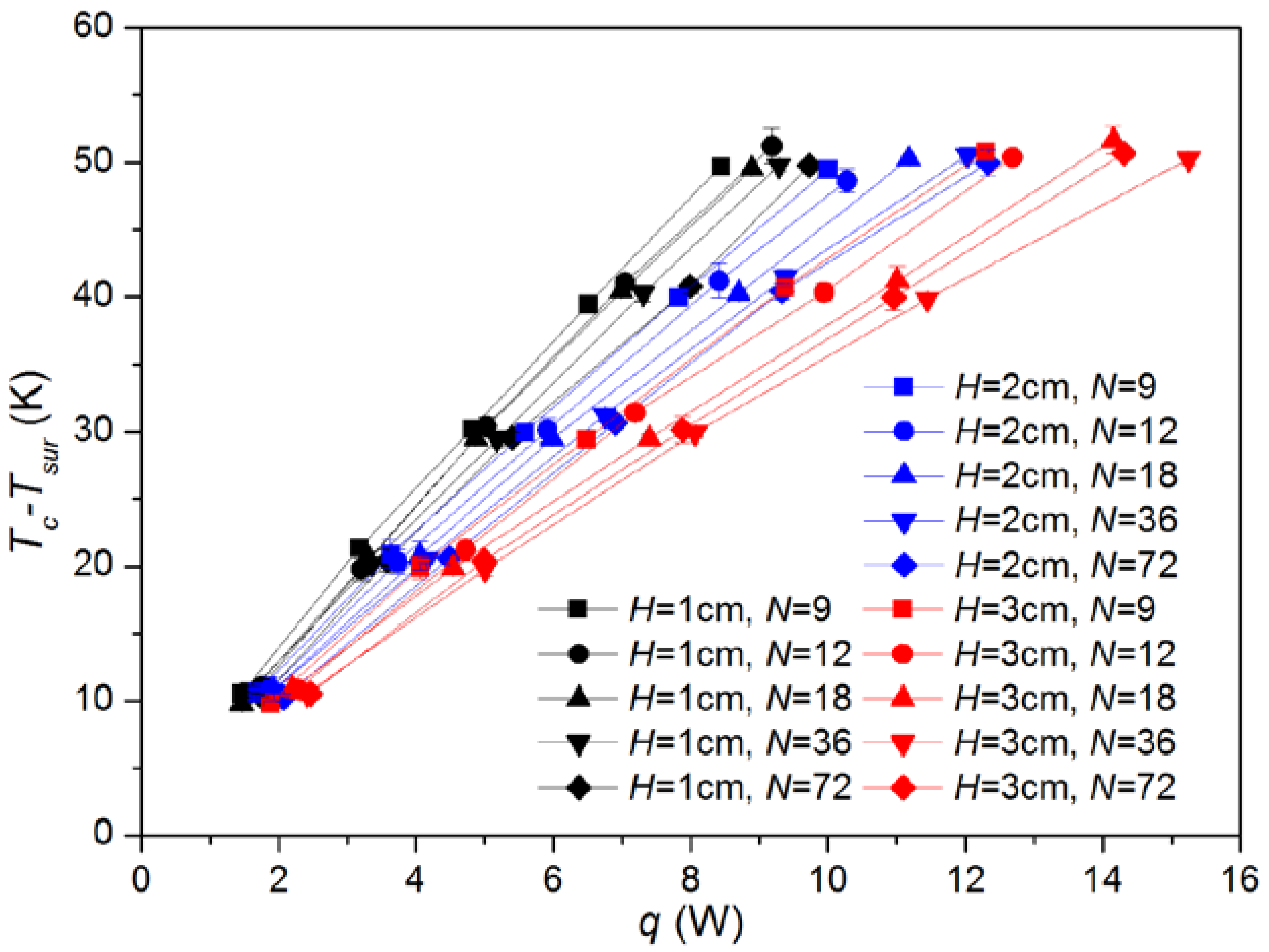
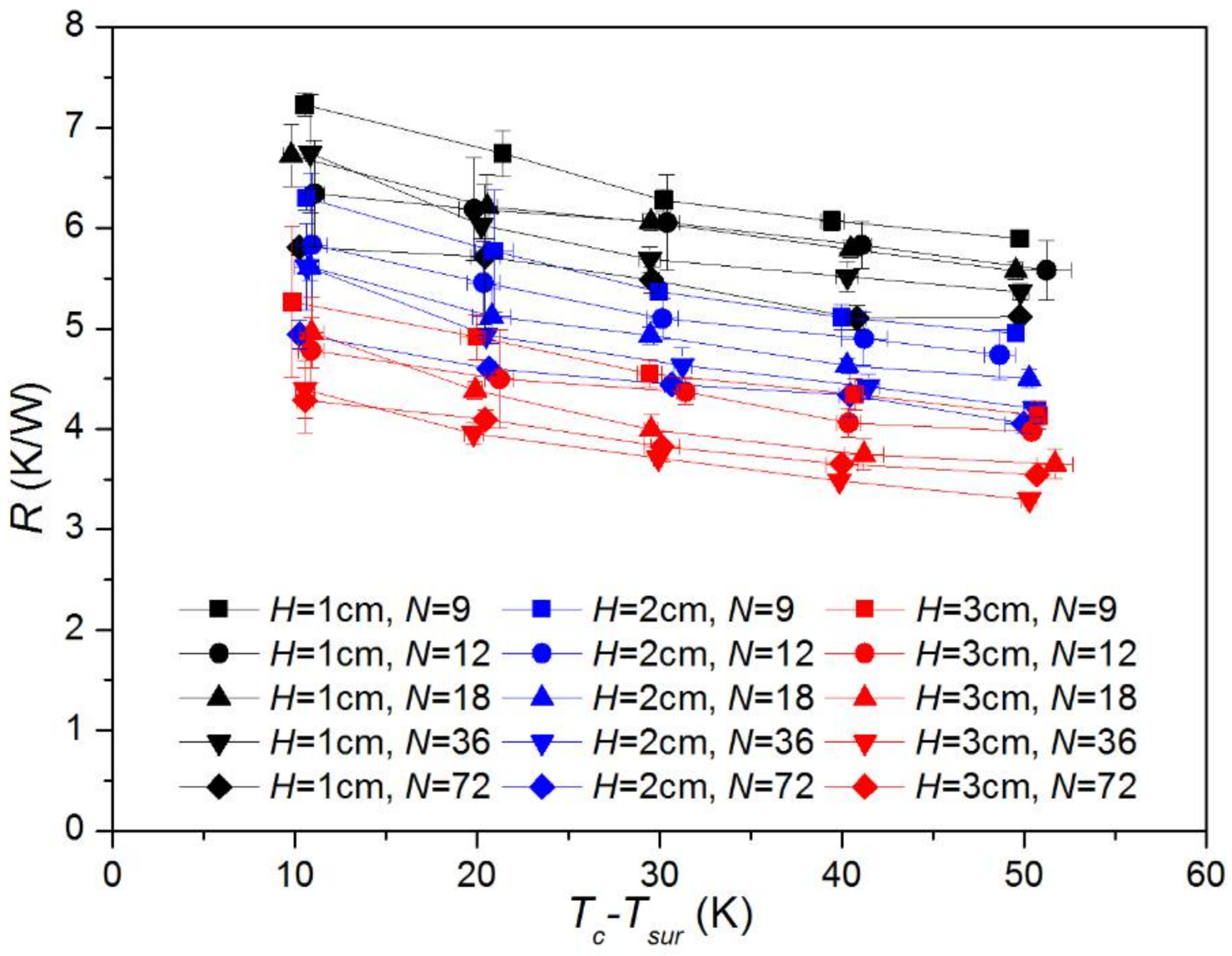
For various finned cylinders, the results of the measured temperature differences between the cylinder surface and ambient air for various heat inputs are shown in Figure 5 and Table 3. The thermal resistances were also calculated and are presented in Figure 6 and Table 3, because the thermal performance can be quantified by using the concept of thermal resistance. The thermal resistance is defined as the difference between the cylinder surface temperature and the ambient temperature per unit heat input.
In Equation (1), R, Tc, Tsur, and q are the thermal resistance, cylinder surface temperature, ambient temperature, and heat input, respectively.
In this study, an experimental correlation for the Nusselt number was developed using the calculated values of the thermal resistances. For this, the Nusselt numbers were calculated from the thermal resistances using Equation (2) below, which is the relationship between the thermal resistance and the Nusselt number.
In Equation (2), h, A, D, NuD, and kf are the heat transfer coefficient, effective surface area, cylinder diameter, Nusselt number, and fluid thermal conductivity, respectively. The effective surface area is given as
where Ab, Af, η, and N are the unfinned base area, fin surface area, fin efficiency, and fin number, respectively, and are given as
In Equations (3)–(5), L, H, t, and ks are the cylinder length, fin height, fin thickness, and solid thermal conductivity, respectively. Equation (6) was obtained from the analysis presented in Lee et al. [18] (Appendix B).
The calculated Nusselt numbers are also listed in Table 3. To create an empirical correlation that expresses the Nusselt number as a function of the fin number, fin height, and temperature difference, the measured Nusselt number was fitted with polynomial functions of various degrees in these variables. As can be easily predicted, a higher degree of polynomial function corresponded to a higher accuracy in the fitting. It was found that the fitted function has satisfactory accuracy when the number of degrees is 2. As a result, the Nusselt number correlation is given as follows.
In Equation (7), the Rayleigh number (RaD) and the ratio of the fin height to the cylinder diameter (H/D) are used as the dimensionless temperature difference and dimensionless fin height, respectively. The Rayleigh number is defined as
In Equation (8), g, β, ν, and α are the gravitational acceleration, volume expansion coefficient of fluid, kinematic viscosity of fluid, and thermal diffusivity of fluid, respectively. For calculating these values, air properties at a temperature of 30 °C were used.
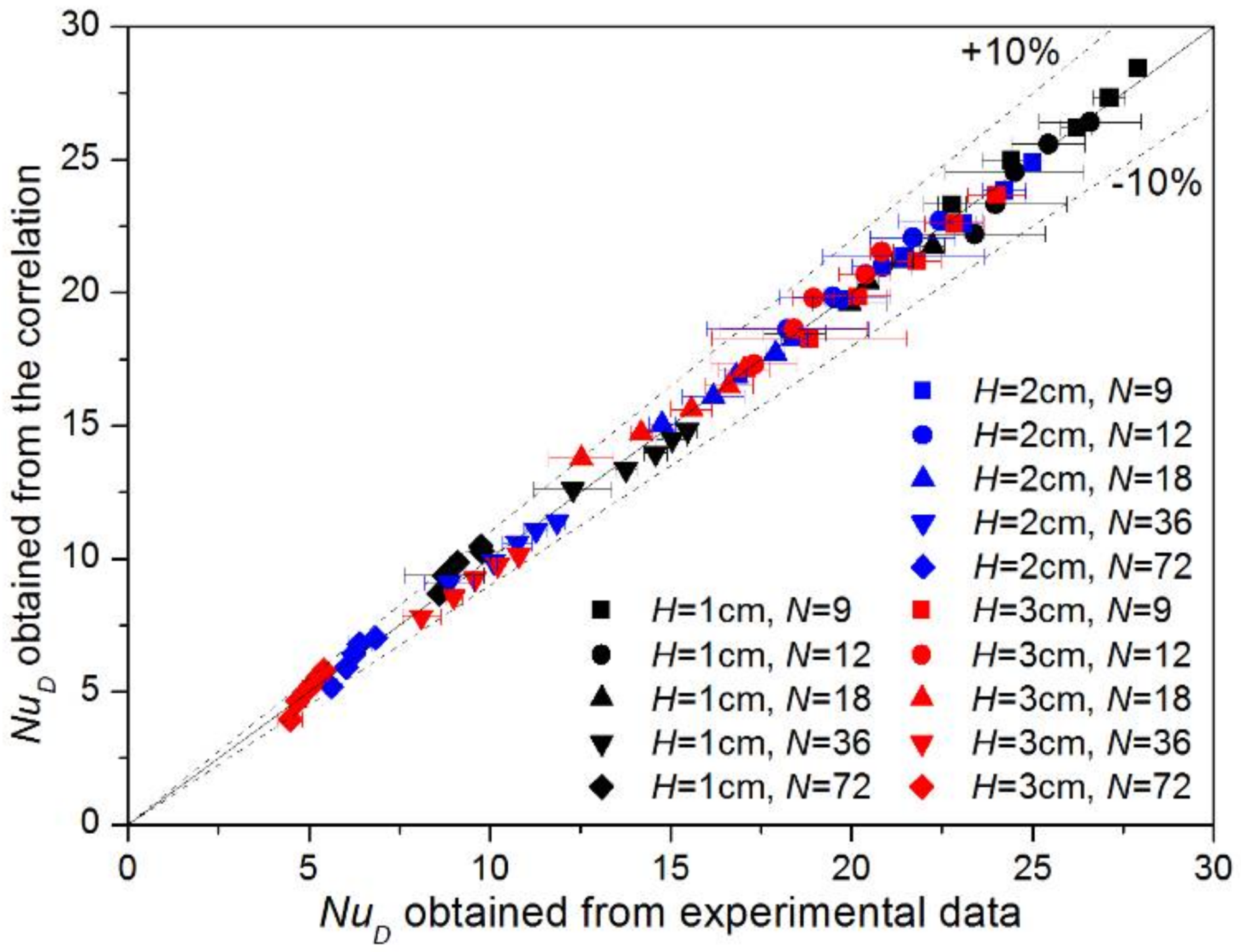
In Figure 7, the Nusselt numbers predicted by the correlation and the measured Nusselt numbers were compared with each other. As shown in the figure, the predicted values and measured values agree well within a relative error of 10%.
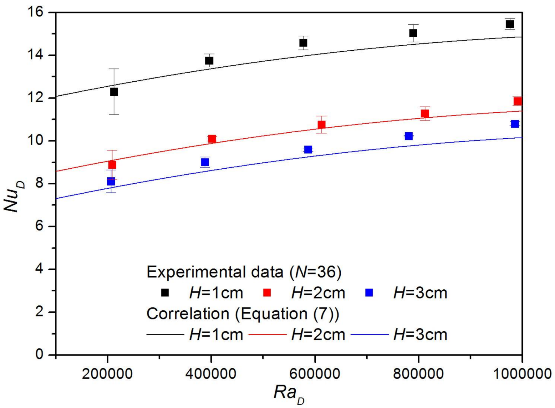
To illustrate the trends of the Nusselt number and demonstrate the degree of accuracy of the correlation, the Nusselt numbers for various fin numbers are shown in Figure 8, and the Nusselt numbers for various fin heights are shown in Figure 9. As shown in the figure, the Nusselt number decreases as the fin number increases. In the case of natural convection, buoyant force is generated as the air around the finned cylinder heats up, and heat is convected away by the air flow driven by the buoyant force. As the fin number increases, the space between the fins becomes narrower and it becomes difficult for the heated air between the fins to flow out, thereby reducing the Nusselt number. Furthermore, as shown in the figure, the Nusselt number decreases as the fin height increases, which is due to the fact that it becomes difficult for the hot air between the fins to flow out as the fin height increases.
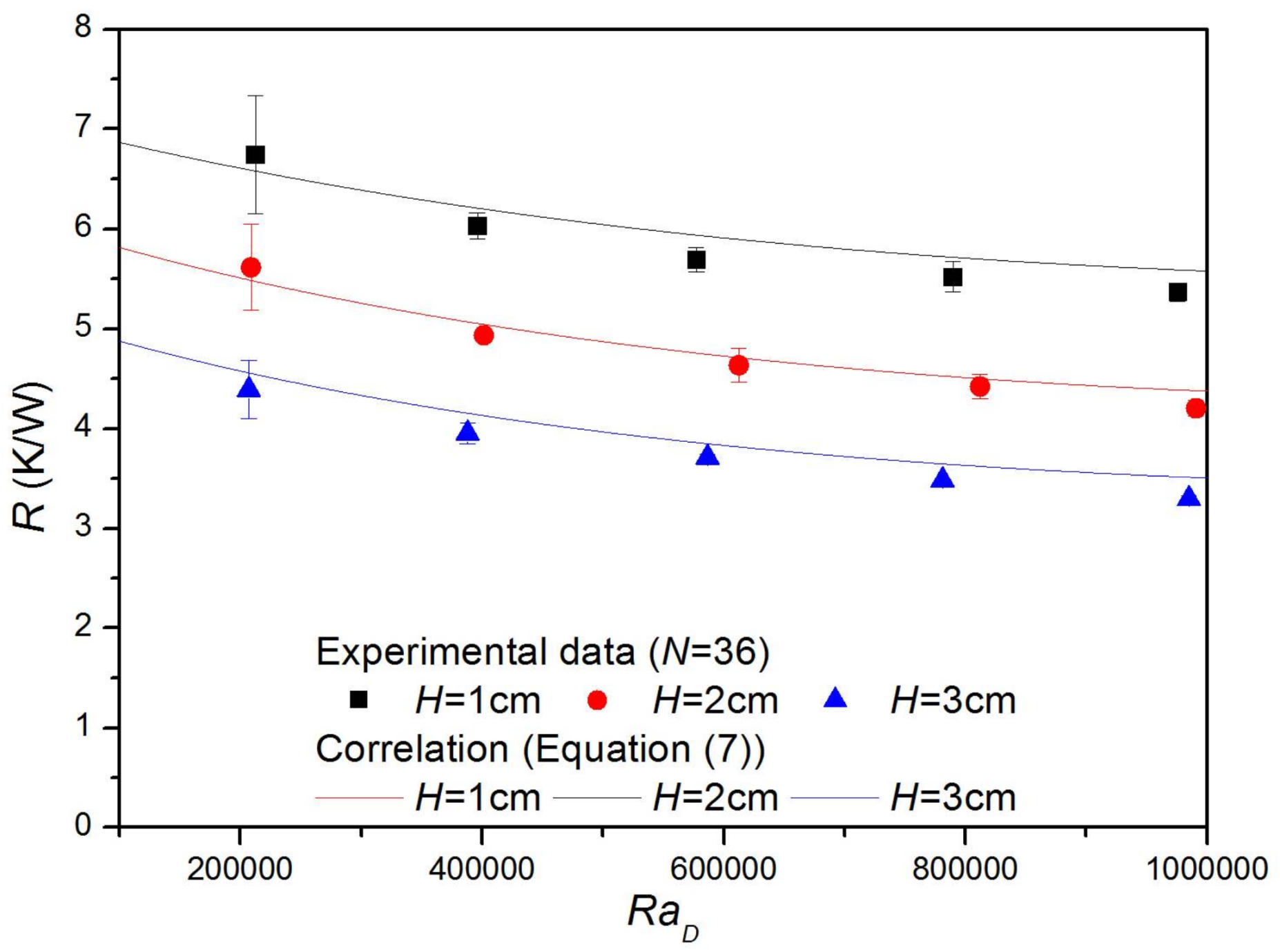
In Figure 10, Figure 11, Figure 12 and Figure 13, several trends of thermal resistances are examined. The thermal resistances for various fin numbers are shown in Figure 10. As can be seen from the figures, the thermal resistance generally decreases with an increase in fin number. To better understand the reason for this tendency, the Nusselt number, effective surface area, and thermal resistance are presented as functions of fin numbers using the correlation in Figure 11. As can be seen in the figure, and as described above, the Nusselt number decreases with an increase in fin number. However, as the fin number increases, the effective surface area increases as well. The thermal resistance is inversely proportional to the Nusselt number and inversely proportional to the effective surface area of the finned cylinder. As the number of fins increases, the effective surface area increases sharply, while the Nusselt number decreases gradually. As a result, the thermal resistance decreases with an increase in fin number. The thermal resistances for various fin heights are shown in Figure 12. As can be seen from the figure, the thermal resistance generally decreases with an increase in fin height. This is because the effective surface area increases sharply as the fin height increases, while the Nusselt number decreases gradually, as shown in Figure 13.
In addition, the thermal resistances for various fin thicknesses are obtained using the correlation in Figure 14. As the fin thickness increases, the thermal resistance tends to increase. The results shown in Figure 10, Figure 11, Figure 12, Figure 13 and Figure 14 can be summarized as follows: in the range where the experiment is conducted, as the fin number, the fin height, and the fin thickness increase, the thermal resistance decreases, in general.
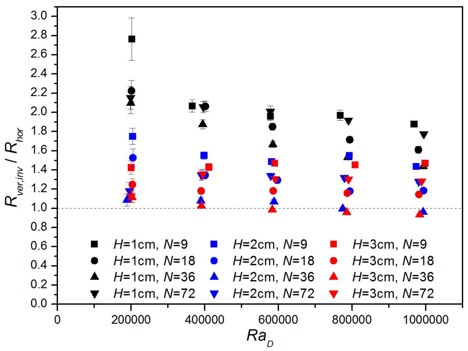
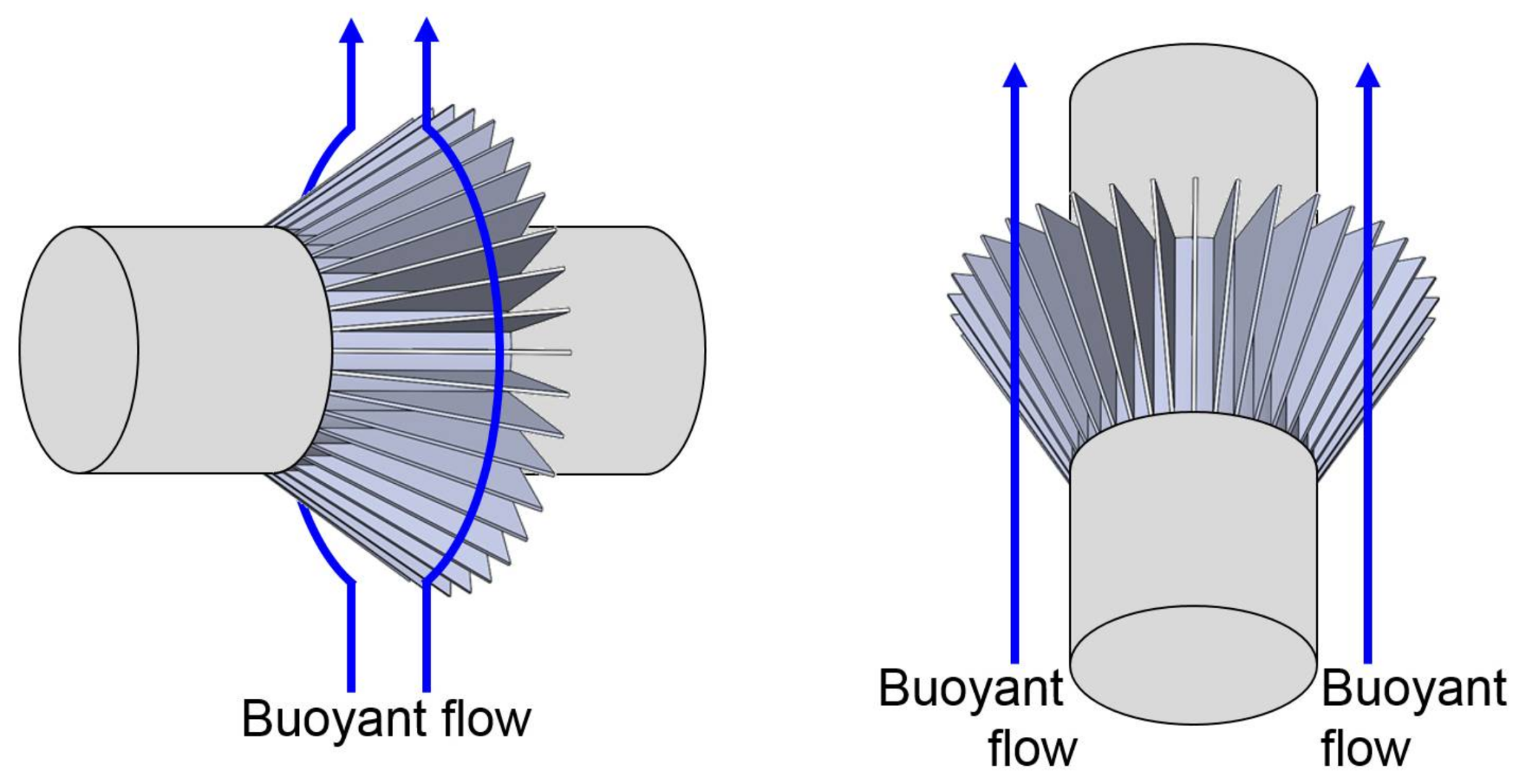
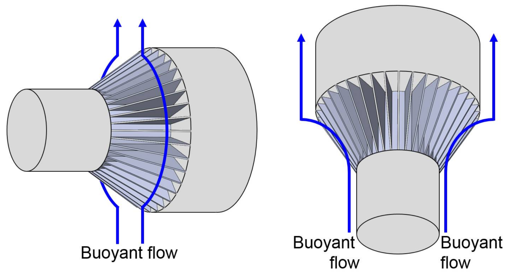
The effect of the orientation of the finned cylinder on the thermal resistance is shown in Figure 15. Figure 15 shows the ratios of the thermal resistances of inverted vertical cylinders with triangular fins, Rver,inv, to those of horizontal cylinders with triangular fins, Rhor, for various fin heights, fin numbers, and Rayleigh numbers. These ratios are above 1 when finned horizontal cylinders have lower resistances, and these ratios are less than 1 when inverted vertical cylinders with triangular fins have lower resistances. In Figure 15, Rhor is calculated from the proposed correlation, and Rver,inv is obtained from experimental data in Kang et al. [19]. In the majority of cases shown in Figure 15, finned horizontal cylinders have lower resistances. The reason why finned horizontal cylinders have lower resistances can be explained as follows: as shown in Figure 16, if only the two sides of the cylinder base are insulated, the finned horizontal cylinder generally cannot have a lower thermal resistance than the finned vertical cylinder. In this case, as presented in Jang et al. [15], the fins on the horizontal cylinder block the upward buoyant flow, and stagnation points and flow separation appear. In contrast, the fins on the vertical cylinder do not block the upward buoyant flow, and stagnation points and flow separation do not appear. As a result, the finned horizontal cylinder generally should have a higher thermal resistance than the finned vertical cylinder. However, in the present study, as shown in Figure 17, not only the sides of the cylinder base, but also one side of the fins, is blocked and insulated. In this case, the buoyant flow around the finned vertical cylinder is significantly impeded by the upper insulating block. This is because the flow must move horizontally before it can ascend from the edge of the upper insulating block. As a result, convection heat transfer from the finned vertical cylinder becomes ineffective. In contrast, the buoyant flow around the finned horizontal cylinder shown in Figure 17 is not impeded by the insulating block. Therefore, convection heat transfer from the finned horizontal cylinder is almost not affected by the insulating block. As a result, the finned horizontal cylinder can have a lower thermal resistance than the finned vertical cylinder. In other words, in cases where buoyant flow around the finned vertical cylinder is significantly impeded by the insulating block, the finned horizontal cylinder can have a lower thermal resistance than the finned vertical cylinder. However, it should be noted that, in the minority of cases shown in Figure 15, the finned horizontal cylinder has a higher resistance than the finned vertical cylinder if the effect of the insulating block on natural convection is small. According to the results shown in the figure, the negative effect of the insulating block tends to be reduced as the Rayleigh number increases.
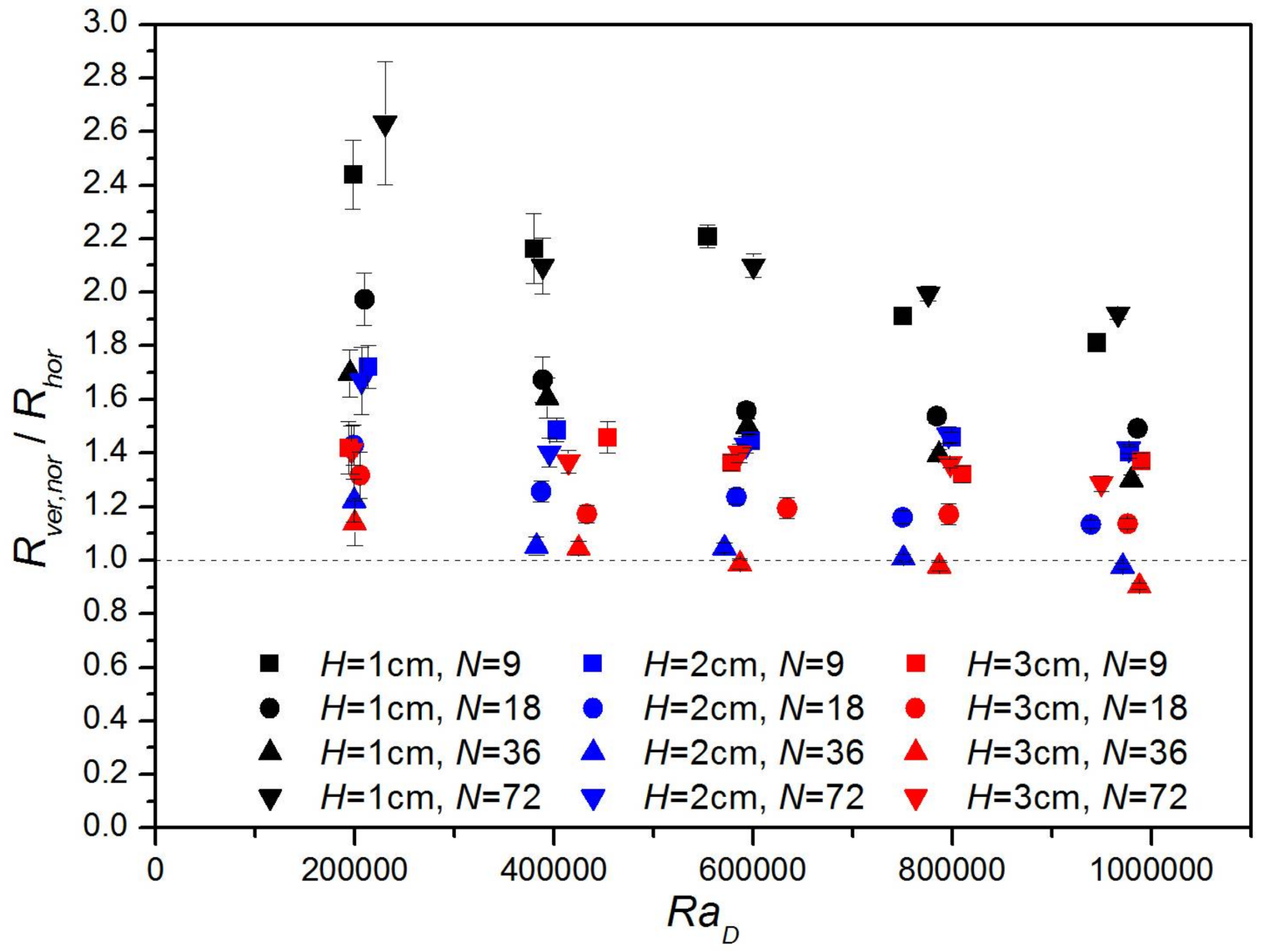
Figure 18 shows the ratios of the thermal resistances of normal vertical cylinders with triangular fins, Rver,nor, to those of horizontal cylinders with triangular fins, Rhor, for various fin heights, fin numbers, and Rayleigh numbers. In Figure 18, Rhor is calculated from the proposed correlation, and Rver,nor is obtained from experimental data in Lee et al. [18]. In the majority of cases shown in Figure 18, finned horizontal cylinders have lower resistances.
4. Conclusions
In this study, the thermal resistances of horizontal cylinders with triangular fins were measured in regard to fin numbers, fin heights, and temperature differences. Thereafter, an empirical correlation was proposed and validated to predict the Nusselt numbers under the following conditions: Rayleigh number, 200,000–1,000,000; fin aspect ratio, 1.6–5.0; and fin number, 9–72. Finally, with the proposed correlation, the effects of fin numbers, fin heights, and fin thicknesses on the thermal resistances of the horizontal cylinders with triangular fins were investigated. It was shown that the thermal resistance generally increases as fin number, fin height, and fin thickness increase. It is expected that horizontal cylinders with triangular fins can be designed for various cooling devices based on the findings of the present study.
Acknowledgments
This research was supported by Nano·Material Technology Development Program through the National Research Foundation of Korea (NRF) funded by Ministry of Science and ICT (NRF-2011-0030285). This work was supported by “Human Resources Program in Energy Technology” of the Korea Institute of Energy Technology Evaluation and Planning (KETEP), granted financial resource from the Ministry of Trade, Industry & Energy, Republic of Korea. (Project No: 2015 4010 200820).
Author Contributions
Gu-Won Lee performed the experiments; Hyun Jung Kim analyzed the data; Dong-Kwon Kim analyzed the data and wrote the paper.
Conflicts of Interest
The authors declare no conflict of interest. The founding sponsors had no role in the design of the study; in the collection, analyses, or interpretation of data; in the writing of the manuscript, and in the decision to publish the results.
Appendix A. Uncertainty Analysis
In the case of the temperature measurement and the heat input measurement, the uncertainty was calculated from Equation (A1).
In Equation (A1), U, B, P, N, s, and t are the uncertainty, bias error, precision error, number of data, standard deviation of data, and t-distribution for a confidence level of 95%, respectively.
The uncertainty in the thermal resistance measurement UR was calculated from Equation (A2).
In Equation (A2), UT and Uq are the uncertainty in the temperature measurement and the uncertainty in the heat input measurement, respectively.
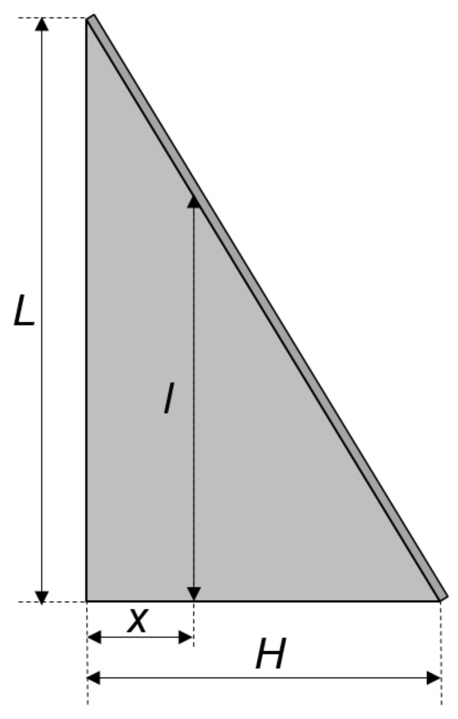
Appendix B. Efficiency of a Triangular Fin
In Equation (A3), Ac,fin and Pfin are the cross-sectional area of the fin and the perimeter of the fin, respectively, and are given as Equation (A4).
The solution of Equation (A3) is given as
Therefore, the heat dissipated by the fin is given as
Finally, the fin efficiency is given as
In Equations (A5) and (A7), I0 and I1 are modified zero-order Bessel function of the first kind and modified first-order Bessel function of the first kind, respectively.
Figure A1.
Single triangular fin.

References
- Oktay, S.; Hannemann, R.J.; Bar-Cohen, A. High Heat from a Small Package. Mech. Eng. 1986, 108, 36–42. [Google Scholar]
- Bar-Cohen, A. Thermal Management of Electric Components with Dielectric Liquids. JSME Int. J. Ser. B Fluids Therm. Eng. 1993, 36, 1–25. [Google Scholar] [CrossRef]
- Park, J.; Shin, M.; Lee, C.C. Measurement of Temperature Profiles on Visible Light-emitting Diodes by Use of a Nematic Liquid Crystal and an Infrared Laser. Opt. Lett. 2004, 29, 2656–2658. [Google Scholar] [CrossRef] [PubMed]
- Narendran, N.; Gu, Y. Life of LED-based White Light Sources. J. Disp. Technol. 2005, 1, 167–171. [Google Scholar] [CrossRef]
- Liu, J.; Tam, W.S.; Wong, H.; Filip, V. Temperature-dependent Light-Emitting Characteristics of InGaN/GaN Diodes. Microelectron. Reliab. 2009, 49, 38–41. [Google Scholar] [CrossRef]
- Chang, M.-H.; Das, D.; Varde, P.V.; Pecht, M. Light Emitting Diodes Reliability Review. Microelectron. Reliab. 2012, 52, 762–782. [Google Scholar] [CrossRef]
- Lasance, C.J.M.; Poppe, A. (Eds.) Thermal Management for LED Applications; Springer: New York, NY, USA, 2014. [Google Scholar]
- Nakayama, W. Thermal Management of Electronic Equipment: A Review of Technology and Research Topics. Appl. Mech. Rev. 1986, 39, 1847–1868. [Google Scholar] [CrossRef]
- Incropera, F.P. Convection Heat Transfer in Electronic Equipment Cooling. J. Heat Transf. 1988, 110, 1097–1111. [Google Scholar] [CrossRef]
- Sparrow, E.M.; Bahrami, P.A. Experiments on Natural Convection Heat Transfer on the Fins of a Finned Horizontal Tube. Int. J. Heat Mass Transf. 1980, 23, 1555–1560. [Google Scholar] [CrossRef]
- Chen, H.-T.; Chou, J.-C. Investigation of Natural-Convection Heat Transfer Coefficient on a Vertical Square Fin of Finned-Tube Heat Exchangers. Int. J. Heat Mass Transf. 2006, 49, 3034–3044. [Google Scholar] [CrossRef]
- Yildiz, Ş.; Yüncü, H. An Experimental Investigation on Performance of Annular Fins on a Horizontal Cylinder in Free Convection Heat Transfer. Heat Mass Transf. 2004, 40, 239–251. [Google Scholar] [CrossRef]
- Hahne, E.; Zhu, D. Natural Convection Heat Transfer on Finned Tubes in Air. Int. J. Heat Mass Transf. 1994, 37, 59–63. [Google Scholar] [CrossRef]
- Kim, H.J.; An, B.H.; Park, J.; Kim, D.K. Experimental study on natural convection heat transfer from horizontal cylinders with longitudinal plate fins. J. Mech. Sci. Technol. 2013, 27, 593–599. [Google Scholar] [CrossRef]
- Jang, D.; Park, S.J.; Yook, S.J.; Lee, K.S. The orientation effect for cylindrical heat sinks with application to LED light bulbs. Int. J. Heat Mass Transf. 2014, 71, 496–502. [Google Scholar] [CrossRef]
- Jang, D.; Kim, D.R.; Lee, K.-S. Correlation of Cross-cut Cylindrical Heat Sink to Improve the Orientation Effect of LED Light Bulbs. Int. J. Heat Mass Transf. 2015, 84, 821–826. [Google Scholar] [CrossRef]
- Kwak, D.B.; Noh, J.H.; Lee, K.S.; Yook, S.J. Cooling performance of a radial heat sink with triangular fins on a circular base at various installation angles. Int. J. Therm. Sci. 2017, 120, 377–385. [Google Scholar] [CrossRef]
- Lee, M.; Kim, H.J.; Kim, D.-K. Nusselt Number Correlation for Natural Convection from Vertical Cylinders with Triangular Fins. Appl. Therm. Eng. 2016, 93, 1238–1247. [Google Scholar] [CrossRef]
- Kang, B.D.; Kim, H.J.; Kim, D.K. Nusselt Number Correlation for Vertical Tubes with Inverted Triangular Fins under Natural Convection. Energies 2017, 10, 1183. [Google Scholar] [CrossRef]
Figure 1.
Horizontal cylinder with triangular fins.

Figure 2.
Photograph of finned cylinder.

Figure 3.
Schematic diagram of experimental setup.
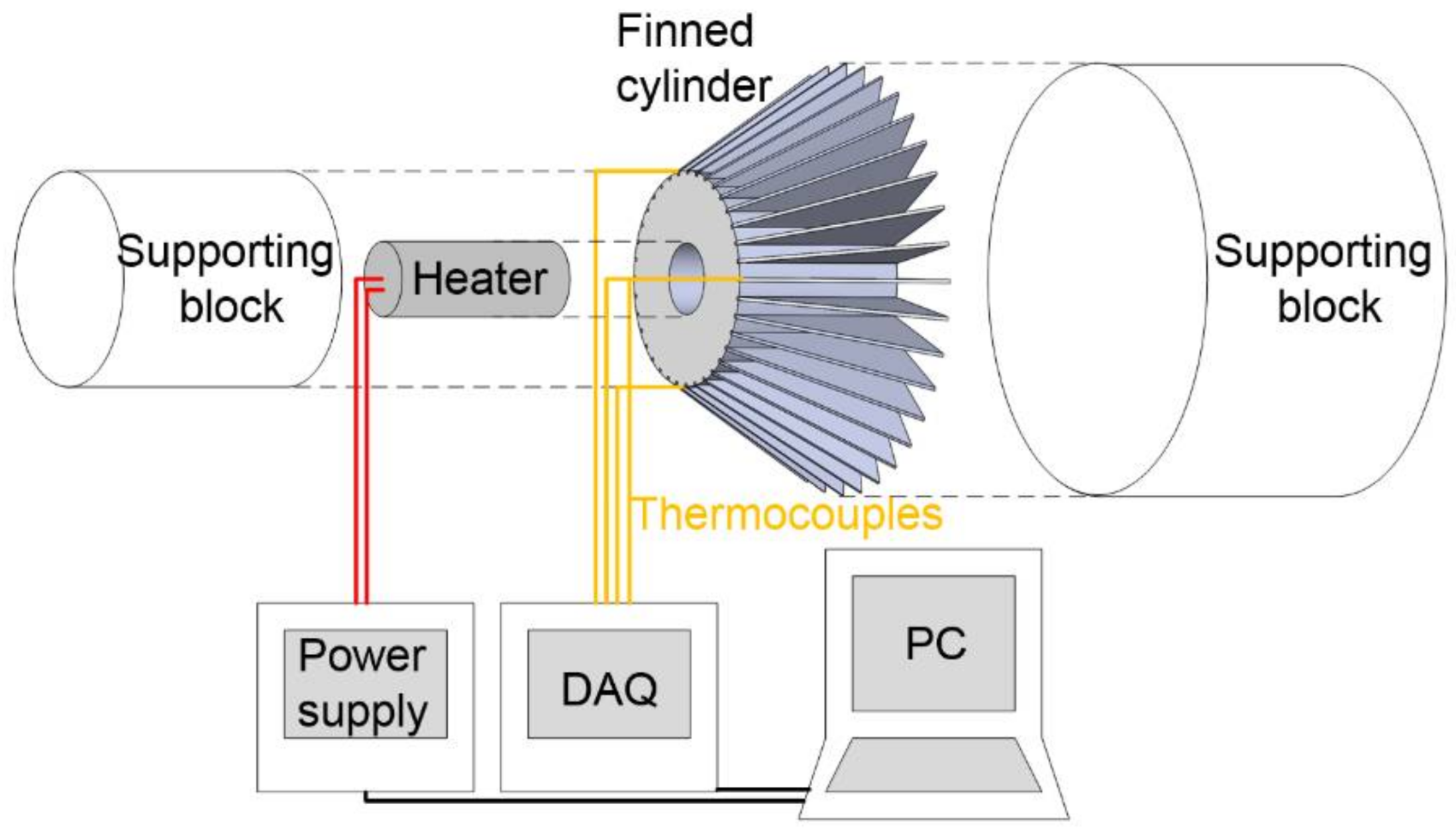
Figure 4.
Photograph of experimental setup.

Figure 5.
Temperature differences for various heat inputs.

Figure 6.
Thermal resistances for various temperature differences.

Figure 7.
Comparison of Nusselt numbers from experimental data and the correlation.

Figure 8.
Nusselt numbers for various fin numbers.
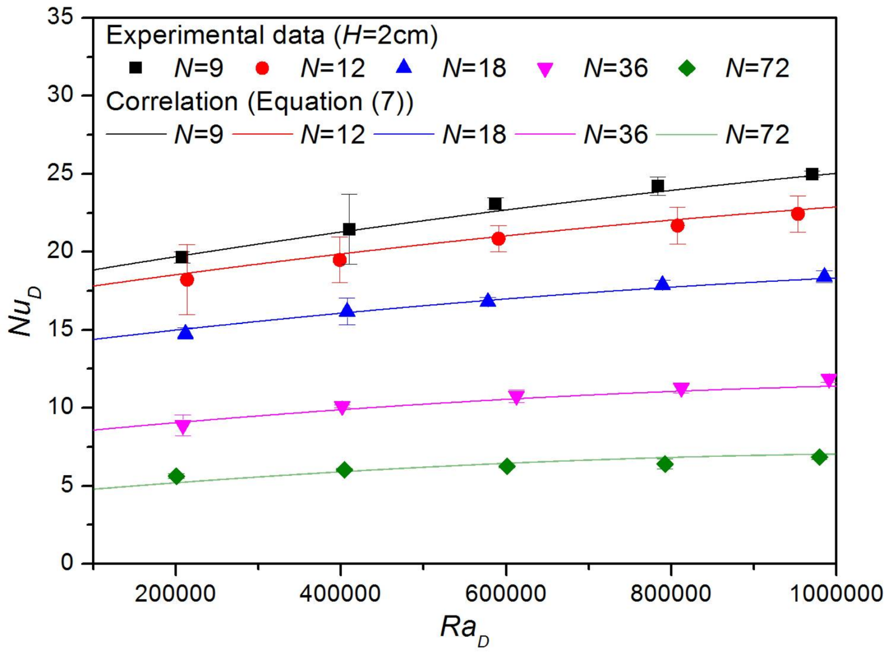
Figure 9.
Nusselt numbers for various fin heights.

Figure 10.
Thermal resistances for various fin numbers.
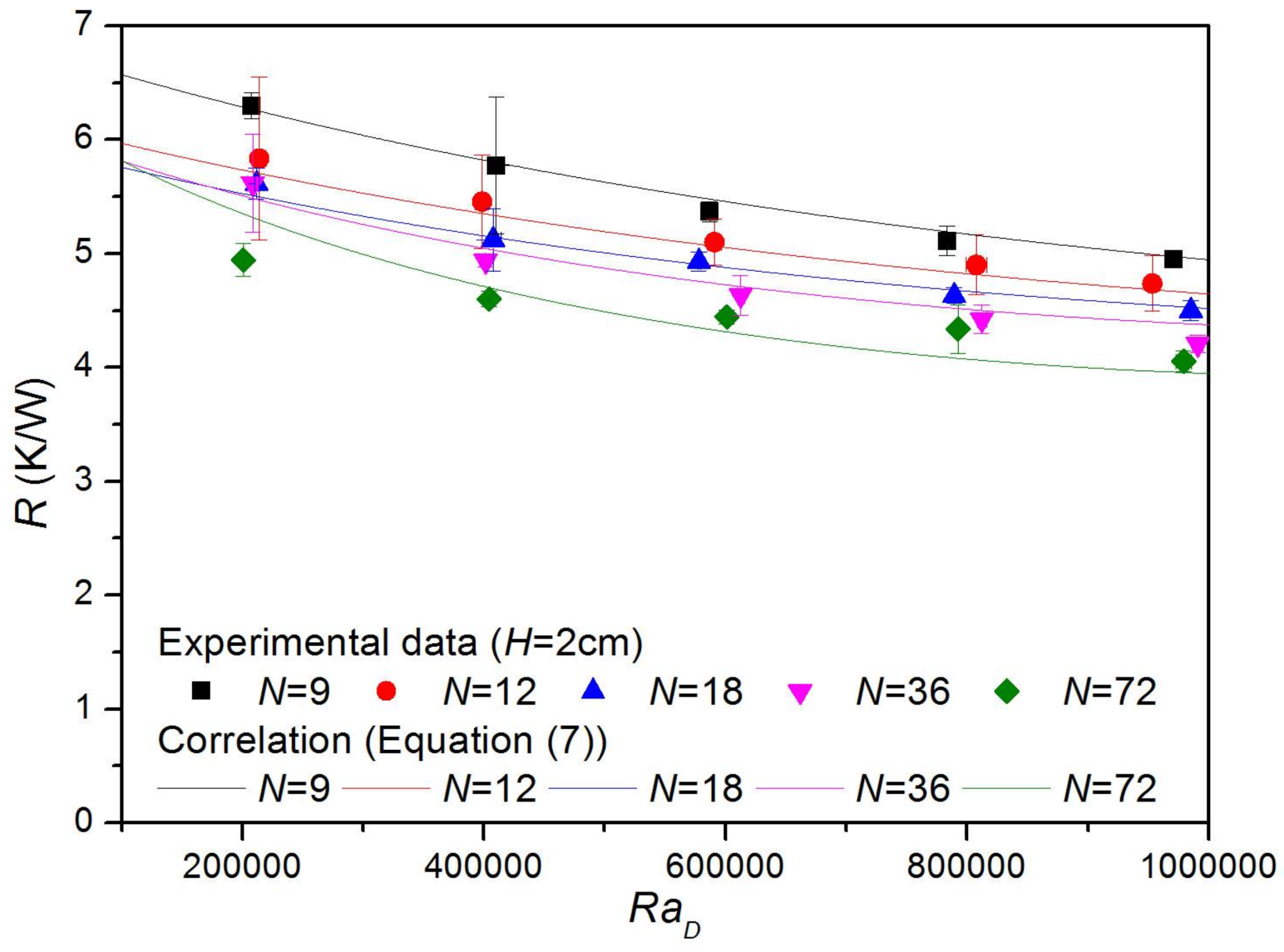
Figure 11.
Effects of fin number on effective surface area, Nusselt number, and thermal resistance.
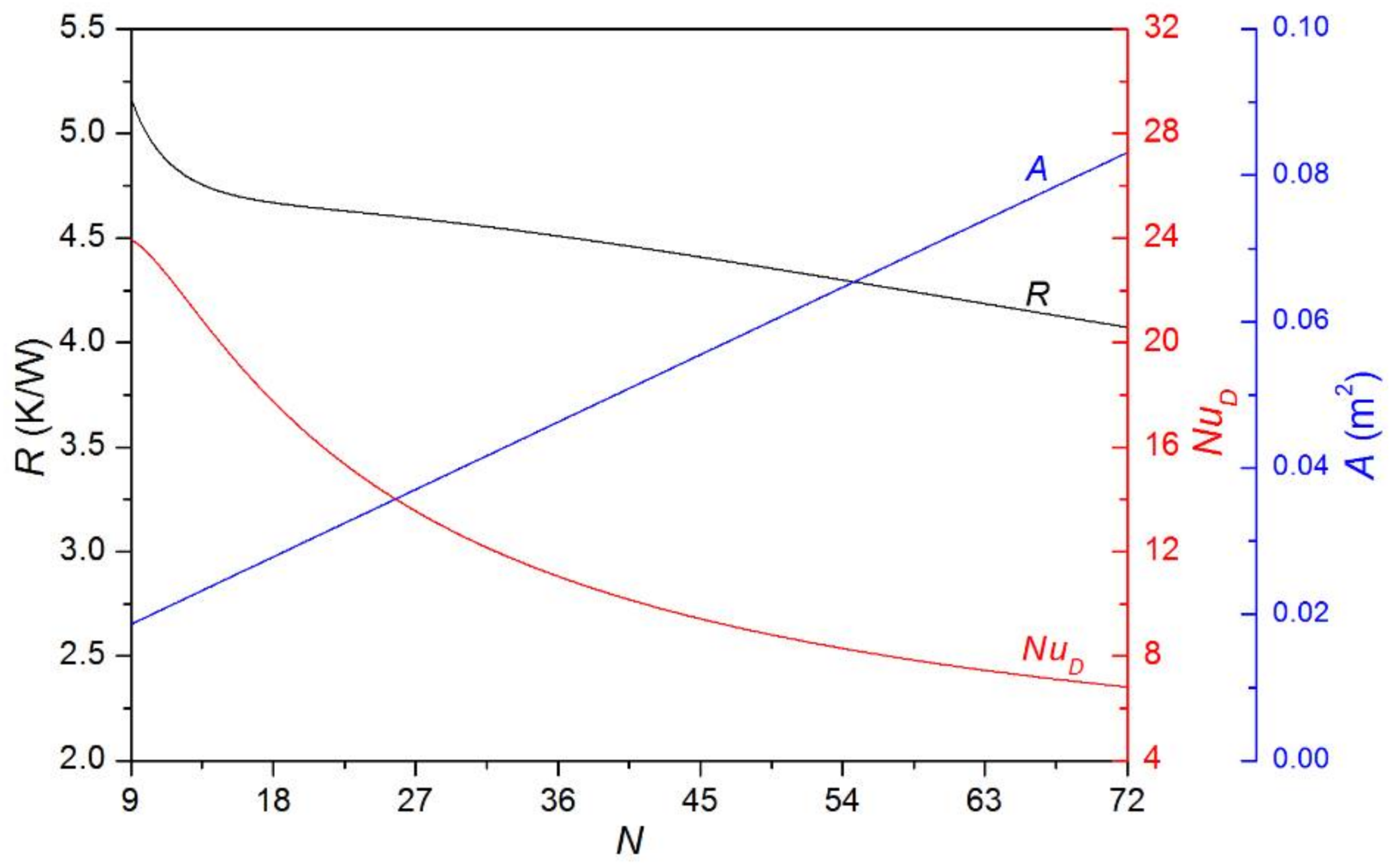
Figure 12.
Thermal resistances for various fin lengths.

Figure 13.
Effects of fin length on effective surface area, Nusselt number, and thermal resistance.
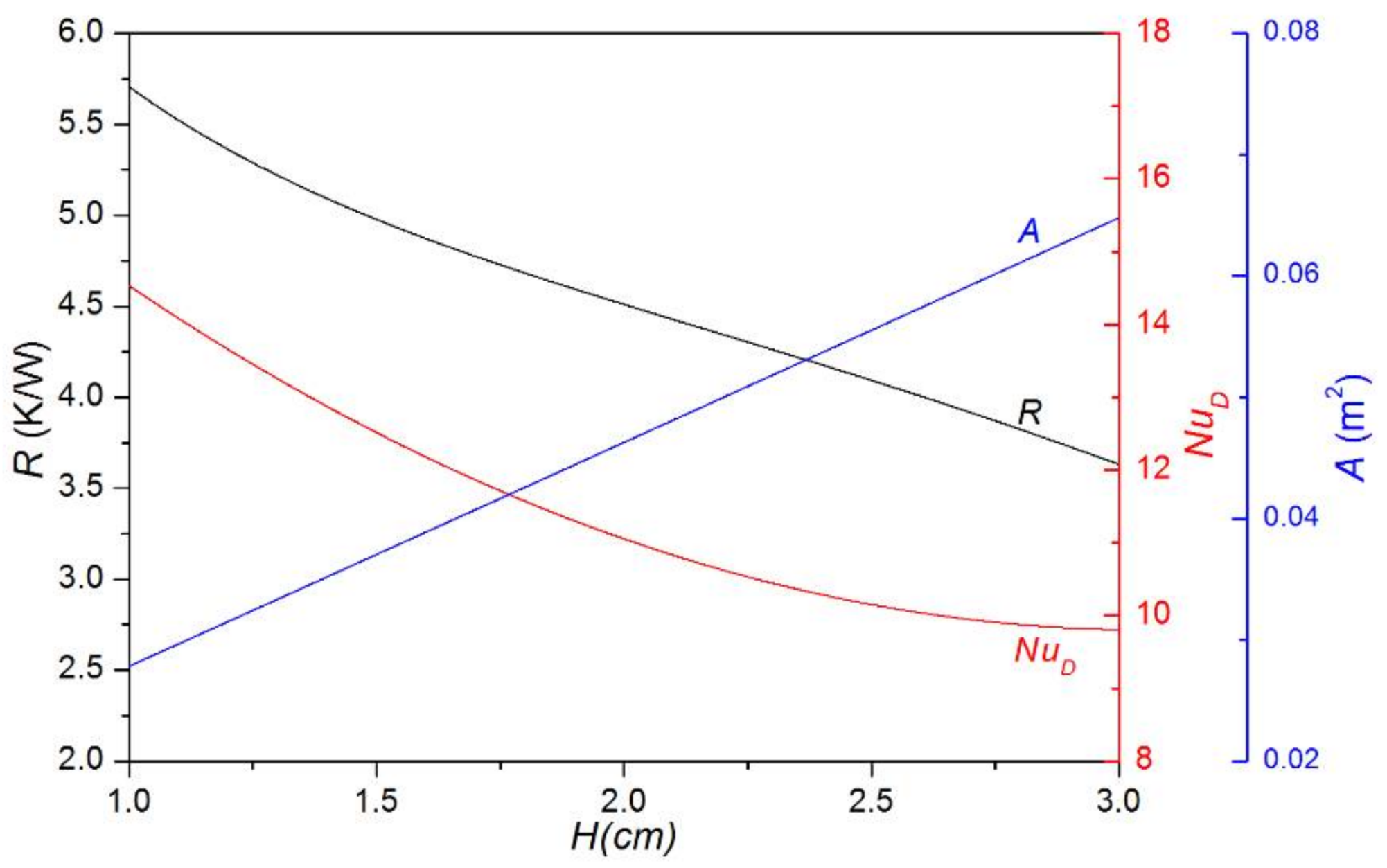
Figure 14.
Effect of fin thickness on thermal resistance (H = 2 cm, RaD = 800,000).
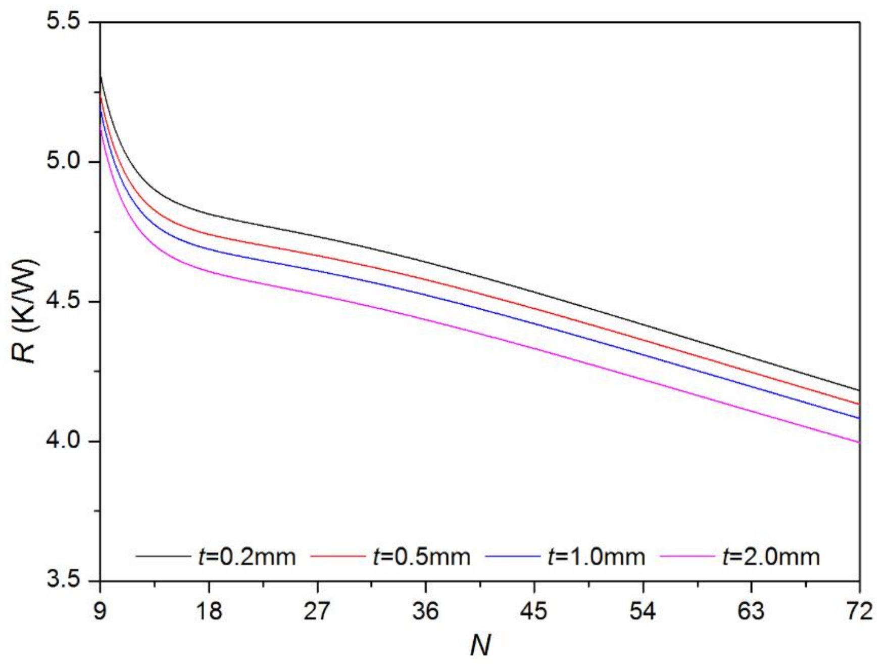
Figure 15.
Ratios of thermal resistances of inverted vertical cylinders with triangular fins to those of horizontal cylinders with triangular fins.
Figure 15.
Ratios of thermal resistances of inverted vertical cylinders with triangular fins to those of horizontal cylinders with triangular fins.

Figure 16.
Finned cylinders when only two sides of cylinder bases are insulated.

Figure 17.
Finned cylinders when sides of fins are also blocked and insulated.

Figure 18.
Ratios of thermal resistances of normal vertical cylinders with triangular fins to those of horizontal cylinders with triangular fins.
Figure 18.
Ratios of thermal resistances of normal vertical cylinders with triangular fins to those of horizontal cylinders with triangular fins.

Table 1.
Summary of previous research works on extended surfaces on horizontal cylinders.
| Extended Surface Type | Authors | Summary |
|---|---|---|
| Vertical square plates | Sparrow and Bahrami [10] |
|
| Chen and Chou [11] |
| |
| Vertical annular plates | Yildiz and Yüncü [12] |
|
| Hahne and Zhu [13] |
| |
| Radial rectangular plates | Kim et al. [14] |
|
| Jang et al. [15] |
| |
| Radial cross-cut plates | Jang et al. [16] |
|
| Radial triangular plates | Kwak et al. [17] |
|
Table 2.
Dimensions of finned cylinders.
| Fin Number (N) | Fin Height (H) | Other Dimensions |
|---|---|---|
| 9 12 18 36 72 | 1 cm 2 cm 3 cm | D = 6 cm L = 5 cm t = 1 mm |
Table 3.
Experimental results.
| N | H | q (W) | Tc − Tsur (K) | R (K/W) | NuD |
|---|---|---|---|---|---|
| 9 | 1 cm | 1.46 ± 0.01 | 10.5 ± 0.2 | 7.23 ± 0.12 | 22.77 ± 0.37 |
| 3.17 ± 0.04 | 21.4 ± 0.4 | 6.74 ± 0.23 | 24.41 ± 0.82 | ||
| 4.82 ± 0.01 | 30.2 ± 0.5 | 6.28 ± 0.10 | 26.22 ± 0.44 | ||
| 6.50 ± 0.01 | 39.5 ± 0.6 | 6.07 ± 0.10 | 27.11 ± 0.45 | ||
| 8.44 ± 0.01 | 49.7 ± 0.2 | 5.90 ± 0.02 | 27.91 ± 0.10 | ||
| 12 | 1 cm | 1.75 ± 0.06 | 11.1 ± 0.6 | 6.34 ± 0.53 | 23.39 ± 1.95 |
| 3.20 ± 0.11 | 19.8 ± 0.9 | 6.19 ± 0.51 | 23.97 ± 1.98 | ||
| 5.02 ± 0.18 | 30.4 ± 0.7 | 6.06 ± 0.47 | 24.50 ± 1.91 | ||
| 7.04 ± 0.13 | 41.1 ± 0.5 | 5.83 ± 0.23 | 25.44 ± 1.02 | ||
| 9.18 ± 0.22 | 51.2 ± 1.3 | 5.58 ± 0.3 | 26.59 ± 1.42 | ||
| 18 | 1 cm | 1.46 ± 0.01 | 9.80 ± 0.5 | 6.72 ± 0.31 | 18.43 ± 0.86 |
| 3.31 ± 0.07 | 20.5 ± 0.6 | 6.21 ± 0.32 | 19.95 ± 1.02 | ||
| 4.87 ± 0.01 | 29.5 ± 0.4 | 6.06 ± 0.09 | 20.45 ± 0.30 | ||
| 6.99 ± 0.04 | 40.5 ± 0.4 | 5.79 ± 0.08 | 21.41 ± 0.30 | ||
| 8.89 ± 0.07 | 49.5 ± 0.1 | 5.57 ± 0.08 | 22.24 ± 0.33 | ||
| 36 | 1 cm | 1.61 ± 0.07 | 10.8 ± 0.3 | 6.74 ± 0.59 | 12.30 ± 1.07 |
| 3.35 ± 0.03 | 20.2 ± 0.3 | 6.03 ± 0.13 | 13.76 ± 0.30 | ||
| 5.18 ± 0.03 | 29.5 ± 0.6 | 5.69 ± 0.13 | 14.58 ± 0.32 | ||
| 7.30 ± 0.09 | 40.3 ± 0.6 | 5.52 ± 0.15 | 15.03 ± 0.41 | ||
| 9.28 ± 0.07 | 49.8 ± 0.4 | 5.37 ± 0.09 | 15.46 ± 0.25 | ||
| 72 | 1 cm | 1.76 ± 0.01 | 10.2 ± 0.1 | 5.81 ± 0.08 | 8.59 ± 0.11 |
| 3.57 ± 0.23 | 20.4 ± 0.8 | 5.71 ± 0.72 | 8.74 ± 1.10 | ||
| 5.39 ± 0.05 | 29.6 ± 0.4 | 5.48 ± 0.13 | 9.11 ± 0.21 | ||
| 7.99 ± 0.09 | 40.8 ± 0.5 | 5.11 ± 0.12 | 9.78 ± 0.23 | ||
| 9.72 ± 0.05 | 49.8 ± 0.3 | 5.12 ± 0.05 | 9.75 ± 0.10 | ||
| 9 | 2 cm | 1.68 ± 0.01 | 10.6 ± 0.2 | 6.30 ± 0.12 | 19.65 ± 0.36 |
| 3.63 ± 0.17 | 20.9 ± 1.0 | 5.77 ± 0.6 | 21.45 ± 2.24 | ||
| 5.58 ± 0.01 | 29.9 ± 0.5 | 5.37 ± 0.09 | 23.07 ± 0.38 | ||
| 7.82 ± 0.10 | 40.0 ± 0.2 | 5.11 ± 0.13 | 24.22 ± 0.60 | ||
| 10.0 ± 0.01 | 49.5 ± 0.4 | 4.95 ± 0.04 | 25.00 ± 0.19 | ||
| 12 | 2 cm | 1.87 ± 0.10 | 10.9 ± 0.8 | 5.83 ± 0.72 | 18.22 ± 2.24 |
| 3.73 ± 0.12 | 20.3 ± 0.9 | 5.46 ± 0.41 | 19.48 ± 1.47 | ||
| 5.91 ± 0.09 | 30.1 ± 0.9 | 5.10 ± 0.2 | 20.84 ± 0.83 | ||
| 8.41 ± 0.21 | 41.2 ± 1.3 | 4.90 ± 0.26 | 21.69 ± 1.17 | ||
| 10.3 ± 0.29 | 48.6 ± 0.9 | 4.74 ± 0.24 | 22.44 ± 1.16 | ||
| 18 | 2 cm | 1.93 ± 0.01 | 10.8 ± 0.3 | 5.61 ± 0.14 | 14.76 ± 0.36 |
| 4.06 ± 0.04 | 20.8 ± 1.1 | 5.12 ± 0.27 | 16.18 ± 0.86 | ||
| 5.98 ± 0.06 | 29.5 ± 0.2 | 4.93 ± 0.09 | 16.8 ± 0.29 | ||
| 8.70 ± 0.07 | 40.3 ± 0.3 | 4.63 ± 0.07 | 17.89 ± 0.27 | ||
| 11.2 ± 0.13 | 50.3 ± 0.2 | 4.50 ± 0.09 | 18.41 ± 0.37 | ||
| 36 | 2 cm | 1.90 ± 0.04 | 10.6 ± 0.7 | 5.62 ± 0.43 | 8.88 ± 0.68 |
| 4.15 ± 0.02 | 20.5 ± 0.2 | 4.93 ± 0.05 | 10.10 ± 0.10 | ||
| 6.74 ± 0.14 | 31.3 ± 0.5 | 4.63 ± 0.17 | 10.76 ± 0.40 | ||
| 9.37 ± 0.14 | 41.4 ± 0.6 | 4.42 ± 0.12 | 11.28 ± 0.32 | ||
| 12.0 ± 0.10 | 50.6 ± 0.6 | 4.20 ± 0.08 | 11.86 ± 0.21 | ||
| 72 | 2 cm | 2.07 ± 0.01 | 10.2 ± 0.3 | 4.94 ± 0.14 | 5.61 ± 0.16 |
| 4.48 ± 0.01 | 20.6 ± 0.3 | 4.60 ± 0.07 | 6.03 ± 0.09 | ||
| 6.90 ± 0.01 | 30.7 ± 0.4 | 4.44 ± 0.06 | 6.25 ± 0.09 | ||
| 9.32 ± 0.27 | 40.4 ± 0.6 | 4.34 ± 0.21 | 6.40 ± 0.32 | ||
| 12.3 ± 0.08 | 50.0 ± 1.0 | 4.05 ± 0.09 | 6.85 ± 0.15 | ||
| 9 | 3 cm | 1.87 ± 0.15 | 9.8 ± 0.2 | 5.26 ± 0.75 | 18.84 ± 2.69 |
| 4.06 ± 0.04 | 20.0 ± 0.9 | 4.92 ± 0.22 | 20.17 ± 0.91 | ||
| 6.47 ± 0.08 | 29.4 ± 0.7 | 4.55 ± 0.14 | 21.80 ± 0.66 | ||
| 9.37 ± 0.20 | 40.7 ± 0.3 | 4.34 ± 0.16 | 22.83 ± 0.82 | ||
| 12.3 ± 0.25 | 50.8 ± 0.1 | 4.13 ± 0.13 | 24.00 ± 0.78 | ||
| 12 | 3 cm | 2.27 ± 0.04 | 10.9 ± 0.7 | 4.78 ± 0.33 | 17.30 ± 1.18 |
| 4.72 ± 0.30 | 21.2 ± 0.8 | 4.50 ± 0.49 | 18.40 ± 2.01 | ||
| 7.19 ± 0.12 | 31.4 ± 0.5 | 4.37 ± 0.13 | 18.94 ± 0.57 | ||
| 9.94 ± 0.20 | 40.4 ± 0.6 | 4.06 ± 0.14 | 20.37 ± 0.72 | ||
| 12.68 ± 0.12 | 50.4 ± 0.3 | 3.97 ± 0.06 | 20.83 ± 0.32 | ||
| 18 | 3 cm | 2.20 ± 0.05 | 10.9 ± 0.7 | 4.96 ± 0.35 | 12.53 ± 0.88 |
| 4.54 ± 0.01 | 19.9 ± 0.4 | 4.38 ± 0.09 | 14.18 ± 0.29 | ||
| 7.39 ± 0.16 | 29.5 ± 0.4 | 3.99 ± 0.14 | 15.57 ± 0.56 | ||
| 11.0 ± 0.23 | 41.2 ± 1.1 | 3.75 ± 0.15 | 16.60 ± 0.67 | ||
| 14.2 ± 0.34 | 51.7 ± 1.0 | 3.65 ± 0.15 | 17.03 ± 0.68 | ||
| 36 | 3 cm | 2.40 ± 0.06 | 10.6 ± 0.5 | 4.39 ± 0.29 | 8.11 ± 0.53 |
| 5.01 ± 0.02 | 19.8 ± 0.5 | 3.95 ± 0.10 | 9.01 ± 0.24 | ||
| 8.06 ± 0.01 | 29.9 ± 0.2 | 3.71 ± 0.03 | 9.59 ± 0.08 | ||
| 11.4 ± 0.01 | 39.9 ± 0.1 | 3.48 ± 0.01 | 10.22 ± 0.03 | ||
| 15.3 ± 0.01 | 50.3 ± 0.4 | 3.3 ± 0.03 | 10.80 ± 0.09 | ||
| 72 | 3 cm | 2.46 ± 0.09 | 10.5 ± 0.5 | 4.29 ± 0.32 | 4.48 ± 0.34 |
| 4.99 ± 0.05 | 20.4 ± 0.3 | 4.1 ± 0.09 | 4.69 ± 0.11 | ||
| 7.88 ± 0.11 | 30.1 ± 1.0 | 3.82 ± 0.15 | 5.02 ± 0.20 | ||
| 11.0 ± 0.16 | 40.0 ± 0.9 | 3.65 ± 0.11 | 5.26 ± 0.16 | ||
| 14.3 ± 0.01 | 50.7 ± 0.2 | 3.54 ± 0.01 | 5.42 ± 0.02 |
© 2018 by the authors. Licensee MDPI, Basel, Switzerland. This article is an open access article distributed under the terms and conditions of the Creative Commons Attribution (CC BY) license (http://creativecommons.org/licenses/by/4.0/).
Share and Cite
MDPI and ACS Style
Lee, G.-W.; Kim, H.J.; Kim, D.-K. Experimental Study on Horizontal Cylinders with Triangular Fins under Natural Convection. Energies 2018, 11, 836. https://doi.org/10.3390/en11040836
AMA Style
Lee G-W, Kim HJ, Kim D-K. Experimental Study on Horizontal Cylinders with Triangular Fins under Natural Convection. Energies. 2018; 11(4):836. https://doi.org/10.3390/en11040836
Chicago/Turabian StyleLee, Gu-Won, Hyun Jung Kim, and Dong-Kwon Kim. 2018. "Experimental Study on Horizontal Cylinders with Triangular Fins under Natural Convection" Energies 11, no. 4: 836. https://doi.org/10.3390/en11040836
Note that from the first issue of 2016, this journal uses article numbers instead of page numbers. See further details here.