A Novel DC-Coil-Free Hybrid-Excited Machine with Consequent-Pole PM Rotor


Department of Electrical Engineering, The Hong Kong Polytechnic University, Hong Kong, China
*
Author to whom correspondence should be addressed.
Energies 2018, 11(4), 700; https://doi.org/10.3390/en11040700
Submission received: 5 February 2018
/
Revised: 22 February 2018
/
Accepted: 24 February 2018
/
Published: 21 March 2018
Abstract
:This paper proposes a new DC coil free hybrid excited machine concept, which has no external field windings. The technical novelty is the integration of field windings and armature windings. DC bias current is injected into the excitation and the field windings in the traditional hybrid excited machine are eliminated. Compared with traditional hybrid-excited machines with additional field windings, the proposed machine can realize a higher slot utilization ratio, hence achieve a higher torque density and a wider flux adjusting range. Another advantage of the proposed machine is that the voltage drop associated with flux regulation is small due to the small DC resistance, and the torque generating capability at the flux regulating region can be improved accordingly. The rotor is specifically designed with magnet-iron sequences and a consequent-pole, in which the permanent magnet and iron pole are alternatively employed. A bi-directional flux modulating effect can be achieved, which can contribute to the magnetic coupling in the air-gap. Analytical derivation is used to describe the operating principle, and the proposed machine was optimally designed using the Tabu search algorithm. A prototype was made, and its performances investigated through experimental tests.
1. Introduction
Permanent magnet (PM) machines have shown significant advantages over electrically excited machines. Generally, PM machines have high efficiency and large torque density when employed with a rare earth magnet, which makes them more competitive than electrically excited machines (EEMs) in large-torque traction applications [1,2,3,4,5,6,7]. Fixed PM excitation is one major drawback of PM machines which means that the air-gap flux cannot be easily regulated as in the EEMs by controlling the excitation current. A well-known flux weakening method of PM machines is to apply negative d-axis current, but the voltage drop involved with the d-axis current reduces the output torque and efficiency accordingly [8,9,10].
Hybrid excited machines (HEMs) have been proposed to integrate the advantages of good flux regulating capability of EEMs and the high torque density of PM machines [11,12,13,14,15,16,17]. There are two kinds of excitation sources employed in HEMs, one is magnetic and the other is field current. The air-gap field is mainly generated by the magnets and field current is used to adjust the air-gap field. According to the investigation reported in [18], HEMs can realize a wide constant power speed range, as well as higher efficiency at the flux weakening region.
Many researches have been reported on HEMs and various novel topologies proposed, and their applications in electric traction widely investigated [19,20,21,22,23]. In order to increase reliability, brushless structure is desirable and the field windings are better being employed on the stator. The magnet can be employed either on the rotor [24,25,26] or on the stator [27,28,29]. Although employing magnet excitation on the stator can result in robust rotor structure, the magnet inevitably takes up some stator space and the space for electric loading is reduced, which reduces the torque density accordingly. Meanwhile, the magnets are located in the stator thermal field, which increases the demagnetization risk of the magnets. Therefore, from the point of achieving good distribution of electric loading and magnetic loading, and reducing the demagnetization risk of magnets, employing magnets on the rotor and field coils on the stator is a better choice for HEMs. Since the field coils of HEMs are only used during flux regulation, and reduce the effective slot area for armature coils, the torque density of HEMs is reduced by the field coils, especially during low-speed operation. The same goes for the flux regulating capability, which is limited by the slot area used for the field windings.
A novel DC-coil-free HEM (DCF-HEM) is proposed in this paper. Compared with traditional HEMs with additional DC coils, the proposed DCF-HEM can achieve higher torque density and wider field adjusting range. The field windings and armature windings in the proposed design are integrated, and DC bias current is injected into the integrated stator winding to achieve flux regulation. The rotor consists of magnet poles and iron segments, namely a magnet-iron consequent-pole rotor, which has a flux modulating effect and can provide PM excitation. The operating principle and field adjusting theory of the proposed DCF-HEM are here analytically investigated. The Tabu search algorithm is used to conduct design optimization of the proposed DCF-HEM. The electromagnetic performances are studied through both the finite element method (FEM) and experimental tests.
2. Machine Configuration
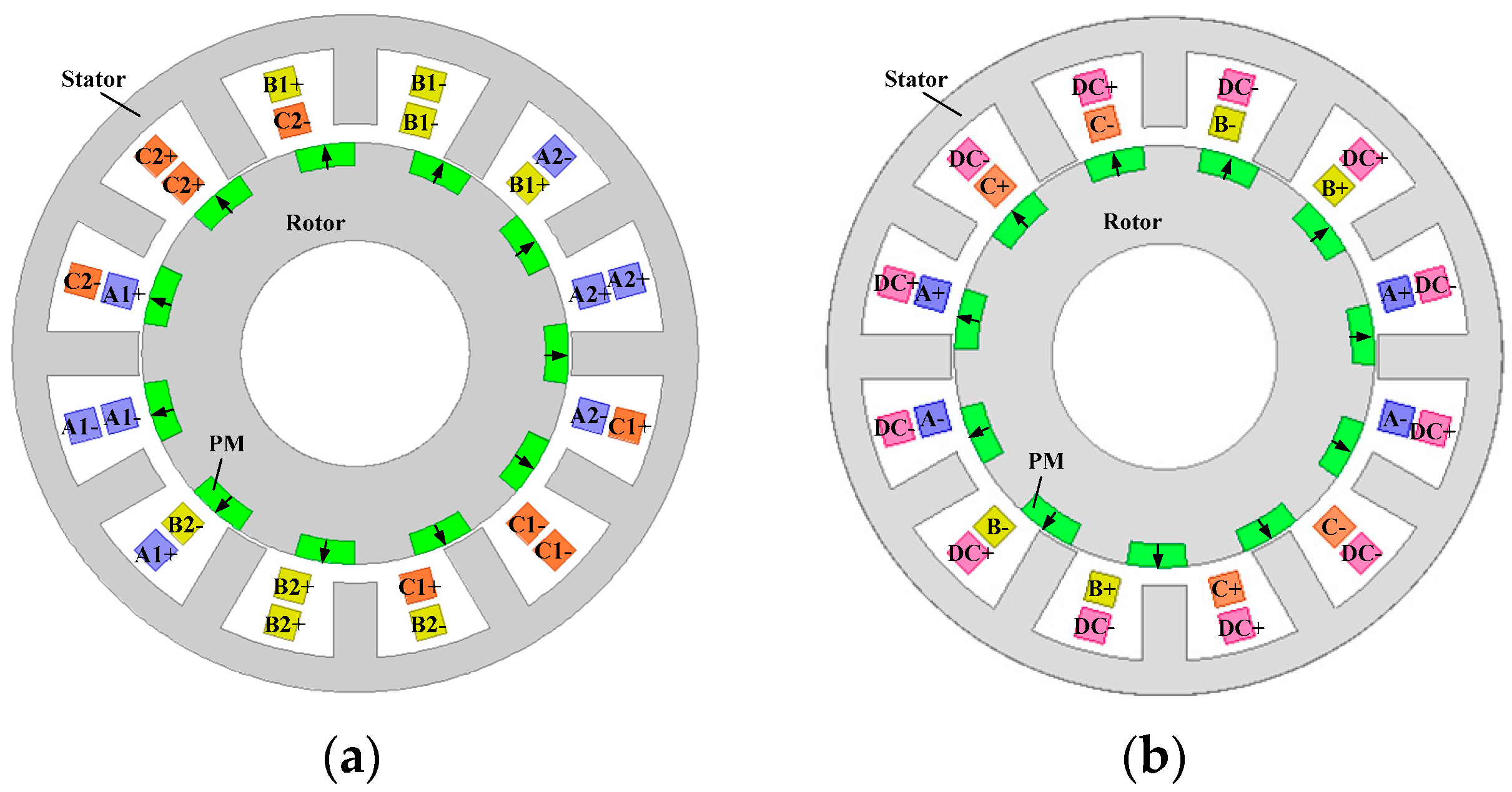
The configuration of the proposed DCF-HEM is shown in Figure 1a. Concentrated windings are employed to reduce the end winding length and copper loss. Different from traditional HEMs with additional field windings, the proposed DCF-HEM has integrated stator winding, and a DC bias component is injected into the armature current to achieve flux regulation. The AC component is responsible for electromagnetic torque production. According to the flux direction of the DC bias current, each phase winding is separated into two parts which are excited by a synchronous sinusoidal current with an opposite DC bias component. Generally, the DC bias current is responsible for flux weakening. However, flux strengthening can also be realized by changing the direction of the DC bias current. The adjacent stator teeth are specifically designed with uneven height to create uneven reluctance distribution, so as to modulate the magnetic field produced by the rotor magnets. The rotor is designed with magnet-iron sequences, and all the magnets are magnetized in a radially outward direction. A rotor magnetic pole-pair consists of a rotor iron pole and its adjacent magnet. Although the magnets are located on the rotor, some specific rotor PM harmonics can be adjusted by the DC bias current due to the effect of the bidirectional flux modulating, therefore the electromagnetic torque and back-EMF can be regulated accordingly. It should be noted that this machine can also be connected as a traditional HEM with additional DC windings, as shown in Figure 1b.
In order to restrict copper loss, an equivalent current expressed in Equation (1) is defined.
where and represent the RMS value and angular frequency of the armature current, respectively, refers to the RMS value of the DC bias current. When the stator windings are applied with DC bias current, the equivalent current is kept unchanged by reducing the RMS value of the armature current. In conditions where the speed of DCF-HEM is lower than the rated speed, no DC bias current is applied since flux regulation is not needed in this region, and all the inverter voltage is used to generate AC current to produce electromagnetic torque. For traditional HEMs with additional field coils, since the field coils are open circuited and useless when flux regulating is not needed, the maximum electromagnetic torque can be expressed as in Equation (2).
where is the slot filling factor, is the slot area, is the current density, is the total PM flux linkage, and and refer to the turns of armature coils and field coils, respectively. Since the armature coils and field coils are incorporated in the proposed DCF-HEM, all the coils can be excited to generate electromagnetic torque. Compared with traditional HEMs, the maximum output torque of the proposed machine is increased and can be expressed as
In order to operate in the high speed region, flux weakening is needed and realized by injecting DC bias current into the windings. For traditional HEMs, only field coils can be used to generate a flux weakening current, and its maximum value is given by
In the proposed machine, all the coils can be excited to generate a flux regulating current and the flux regulating capability is increased. The theoretical maximum flux regulating current can be expressed in Equation (5), in which stator windings are only excited by DC bias current and the AC component is zero.
3. Mathematical Modeling
The principle of flux modulating caused by uneven permeance distribution is reported in [30]. In the proposed DCF-HEM, bi-directional flux modulating effect is the operating basis. Similar to the pole-pair combination of magnetic gear, the pole-pair number (PPN) of AC current pα, PPN of DC bias current pf and PPN of rotor PMs pr are governed by
Since the stator windings are concentrated, the PPN of the DC bias current pf equals half of the stator slot number Ns.
It can be easily observed that the air-gap field has three components, which are generated by the armature current, DC bias current, and rotor PMs, respectively. In order to give a deep insight into the operating principle and flux adjusting theory of the proposed DCF-HEM, the coupling mechanism of these three magnetic fields was analytically studied through harmonic analysis.
3.1. Air-Gap Flux Generated by Rotor PMs
Through multiplying air-gap permeance and magnetomotive force (MMF), the air-gap flux density is obtained. The MMF of rotor PMs can be assumed as square waveform, and can be expressed in the Fourier series, as given in Equation (8).
where refers to the harmonic order, refers to the MMF amplitude of the ith harmonic, is the circumferential position, and are the angular speed and initial position of the rotor, respectively. The bi-directional flux modulating effect can be realized because both the stator and rotor have uneven permeance distribution. The air-gap permeance function of the stator and rotor can be expressed in the Fourier series, as given in Equations (9) and (10), respectively.
where and refer to the average value and amplitude of the νth harmonic of stator permeance, respectively. and refer to the average value and amplitude of the nth harmonic of rotor permeance, respectively. With Equations (9) and (10), the air-gap permeance function of the proposed DCF-HEM can be obtained, as given in Equation (11).
Therefore, the air-gap flux density generated by rotor PMs can be obtained by multiplying Equations (8) and (11), as given in Equation (12).
It can be seen that the air-gap flux density of rotor PMs has four harmonic groups. The first and third items, as well as the second and fourth items can be combined, and Equation (12) can be rewritten as:
The first item in Equation (13) refers to the rotor PM harmonics considering rotor saliency, and the second item refers to additional harmonics introduced by the flux modulating effect of the stator.
3.2. Air-Gap Flux Generated by DC Bias Current
The air-gap flux density of the DC bias current can be obtained in the same way as the air-gap flux density of rotor PMs. Equation (14) gives the expression of the MMF of the DC bias current
where is the stator winding turns, and refers to the stator slot opening. By multiplying Equations (11) and (14), the air-gap flux density of the DC bias current can be obtained, as given in Equation (15).
In which the first item refers to the DC bias current harmonics considering stator saliency, and the second item refers to additional harmonics introduced by the flux modulating effect of the rotor. It should be noted that the harmonics excited by the DC bias current only exist in the flux regulating process. When flux regulating is not needed, the DC bias current is zero, and harmonics in Equation (15) do not exist in this case.
3.3. No Load Flux Linkage
From Equations (13) and (15), we can find that the second item in these two equations has the same PPN and rotating speed, which means the second harmonic group in Equation (13) can be adjusted by the DC bias current. The total excitation flux can be obtained by summing up Equations (13) and (15), as given in Equation (16).
The no load flux linkage of sub-phase one and sub-phase two can be calculated as given in Equations (17) and (18), respectively.
where is the air-gap radius, and refer to the stack length and coil initial position, respectively. One can see that the no-load flux linkage has three components, the first and third items are rotating components, which vary with the time. The second item is the DC bias component. It should be noted that the DC bias components of the flux linkage in sub-phase one and sub-phase two have opposing direction.
3.4. Back EMF
The back-EMF can be calculated from the derivation of open-circuit flux linkage. Since the derivation of a constant is zero, the DC bias component in the flux linkage does not influence back-EMF, therefore the back-EMF of the two sub-phases is equal, as given in Equation (19).
One can find that the back EMF has two parts, in which the first one is generated only by the rotor PMs, and the second one is produced by the DC bias current and rotor PMs simultaneously. Therefore, by controlling the DC bias current, the second item of the back EMF can be regulated effectively.
4. Optimization and Finite Element Analysis
4.1. Design Optimization
Before investigating the electromagnetic performances, an optimization method coupled TS-FEM is used to conduct design optimization. Generally, the machine in traction vehicle should have: (1) High torque density to fulfill the requirements during start-up and climbing; (2) Low torque ripple to reduce the vibration and noise; (3) High efficiency to reduce power consumption and increase the mileage range. Therefore, three objectives are considered during optimization, which are the average electromagnetic torque , torque ripple , and efficiency . The optimization problem is expressed as
In which and refer to the geometric parameters and their constraints.
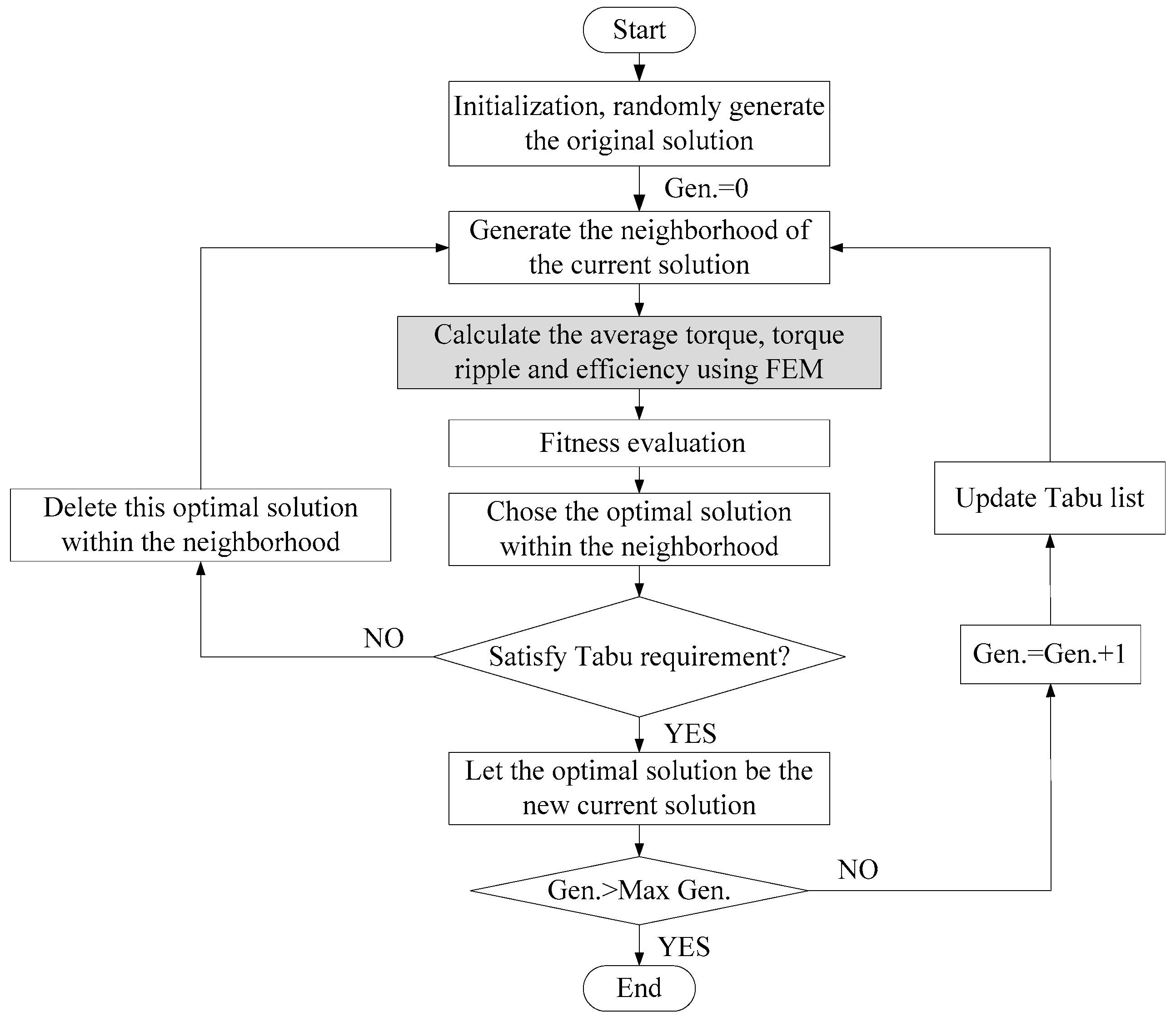
The flowchart of the optimization process is shown in Figure 2, in which the optimization algorithm and finite element analysis are directly coupled and the whole process is automatic. The armature current density is 8 A/mm2 and DC bias current is not applied. The optimization algorithm randomly generates the initial values of the optimized parameters within their ranges, which is labeled as the current solution x and a series of neighborhood solutions x1, x2,…, xp are generated around x. These solutions are automatically passed to the Maxwell software. Maxwell conducts a finite element calculation and returns the torque, torque ripple, and efficiency to the optimization algorithm for fitness evaluation and the optimal solution within the neighborhood is chosen. The optimal solution is labeled as the new current solution x*, and the optimization algorithm generates a new neighborhood around this optimal solution and starts a new circulation. The Tabu search algorithm is investigated in [31] and multi-level optimization of electrical machines is reported in [32,33]. Although the electromagnetic performances can be influenced by many factors, only structural parameters are optimized in this paper, as given in Table 1. The optimization is conducted on a prototype with 11 rotor pole-pairs and 12 stator slots. Since the DC bias current is not a fixed value, it can be changed from zero to the maximum value which corresponds to the maximum current density. Therefore, there is no need to optimize the DC bias current.
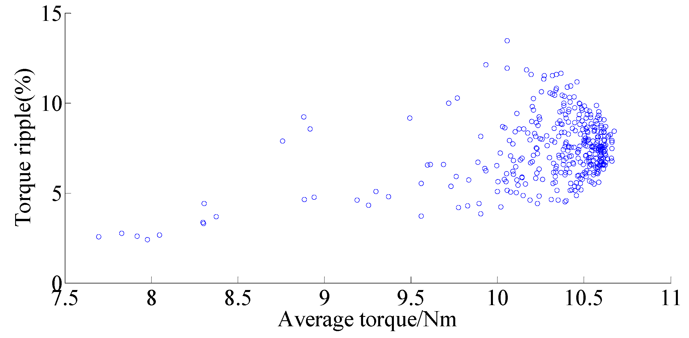
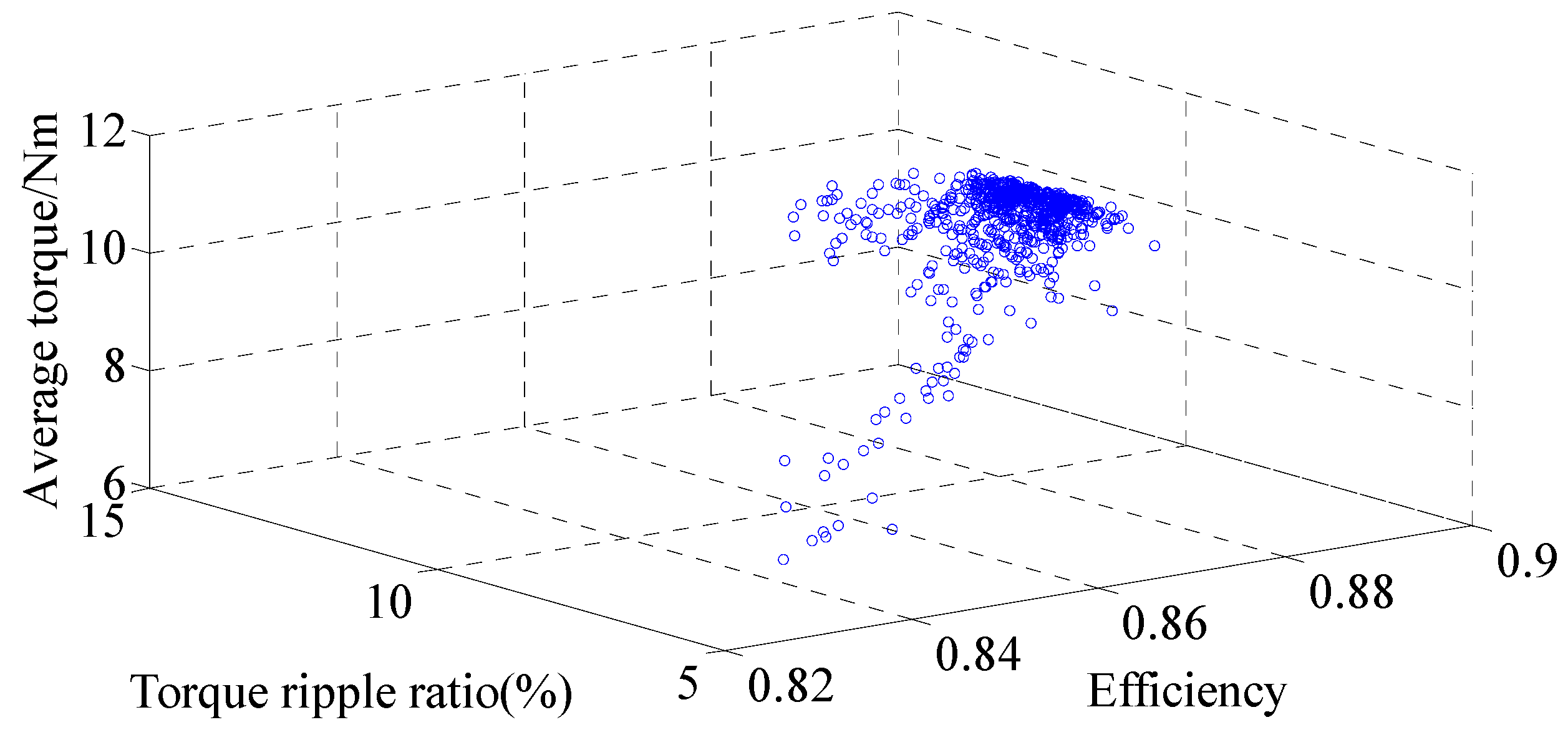
The optimization results of average torque and efficiency are given in Figure 3. One can find that when the output torque becomes larger, the machine efficiency tends to increase. Therefore, when the proposed DCF-HEM is designed with a large output torque, high efficiency can also be achieved. Figure 4 shows the optimization results of average torque and torque ripple. One can see that the torque ripple varies disorderly when the average torque increases, and no clear regularity can be found between the change of average torque and torque ripple. The three-objective Pareto results are given in Figure 5.
With the results of multi-objective optimization, a single objective optimization is conducted to maximize the output torque. The constraints are that the efficiency should be greater than 0.88 and the torque ripple lower than 10%. The objective function is given as
4.2. Finite Element Analysis
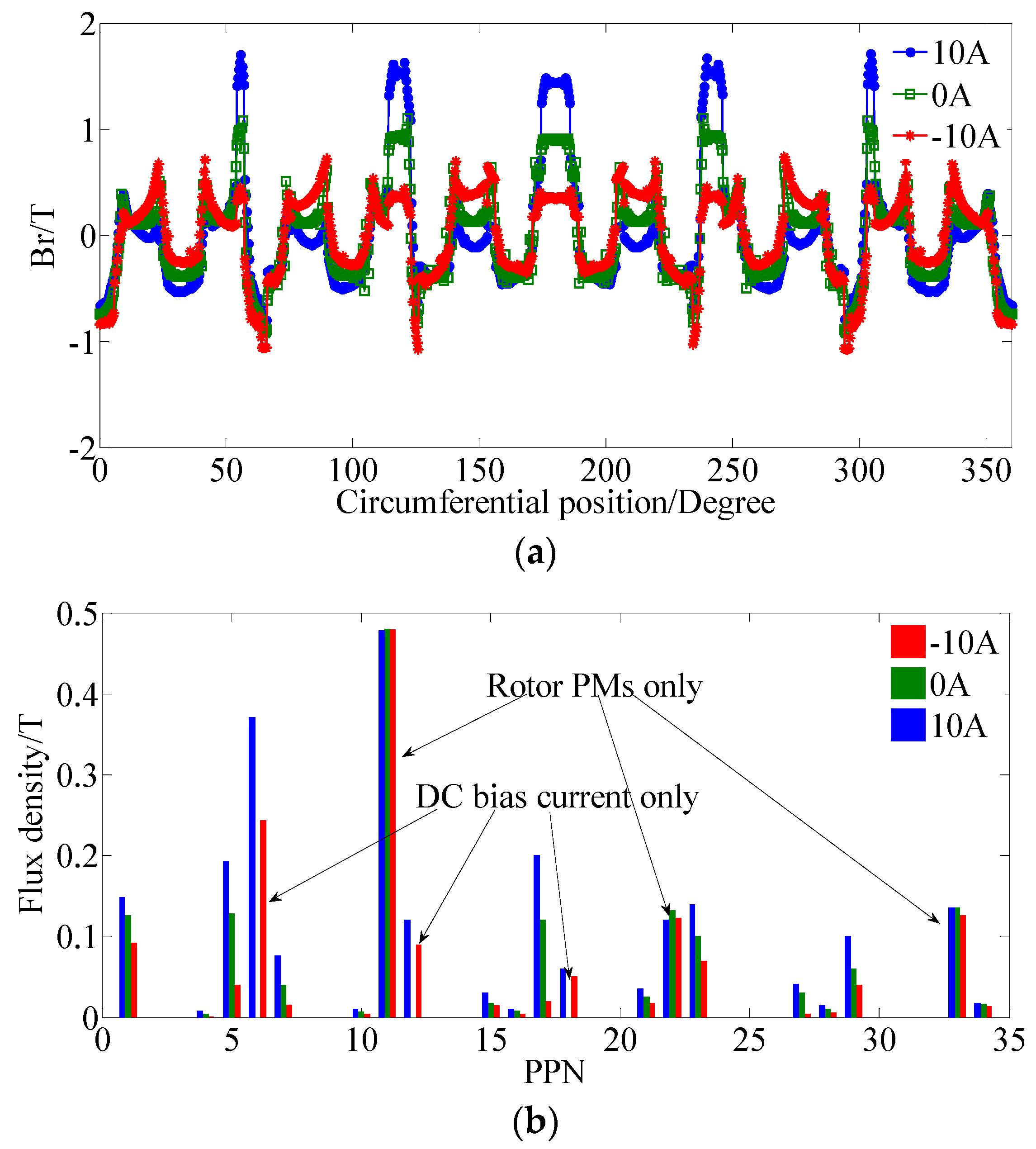
FEM is used to simulate the electromagnetic performances of DCF-HEM. Firstly, the no-load flux density in the air-gap when applied with different DC bias currents iscalculated and given in Figure 7, as well as the harmonic spectrums. The 10 A, 0 A, and −10 A are the values of the DC bias current. One can see that the air-gap flux can be efficiently adjusted by the DC bias current. The results in Figure 7 show a good match with the mathematical derivation given in Equation (16). Harmonic with 11 pole-pairs is the fundamental component of the rotor PM field, which corresponds to the first item of Equation (16) and cannot be controlled by the DC bias current as given in Figure 7. Harmonic with six pole-pairs is only excited by the DC bias current, which corresponds to the second item of Equation (16). And harmonic with five pole-pairs is generated by both the rotor PM and DC bias current, which corresponds to the third item of Equation (16) and can be regulated by controlling the DC bias current.
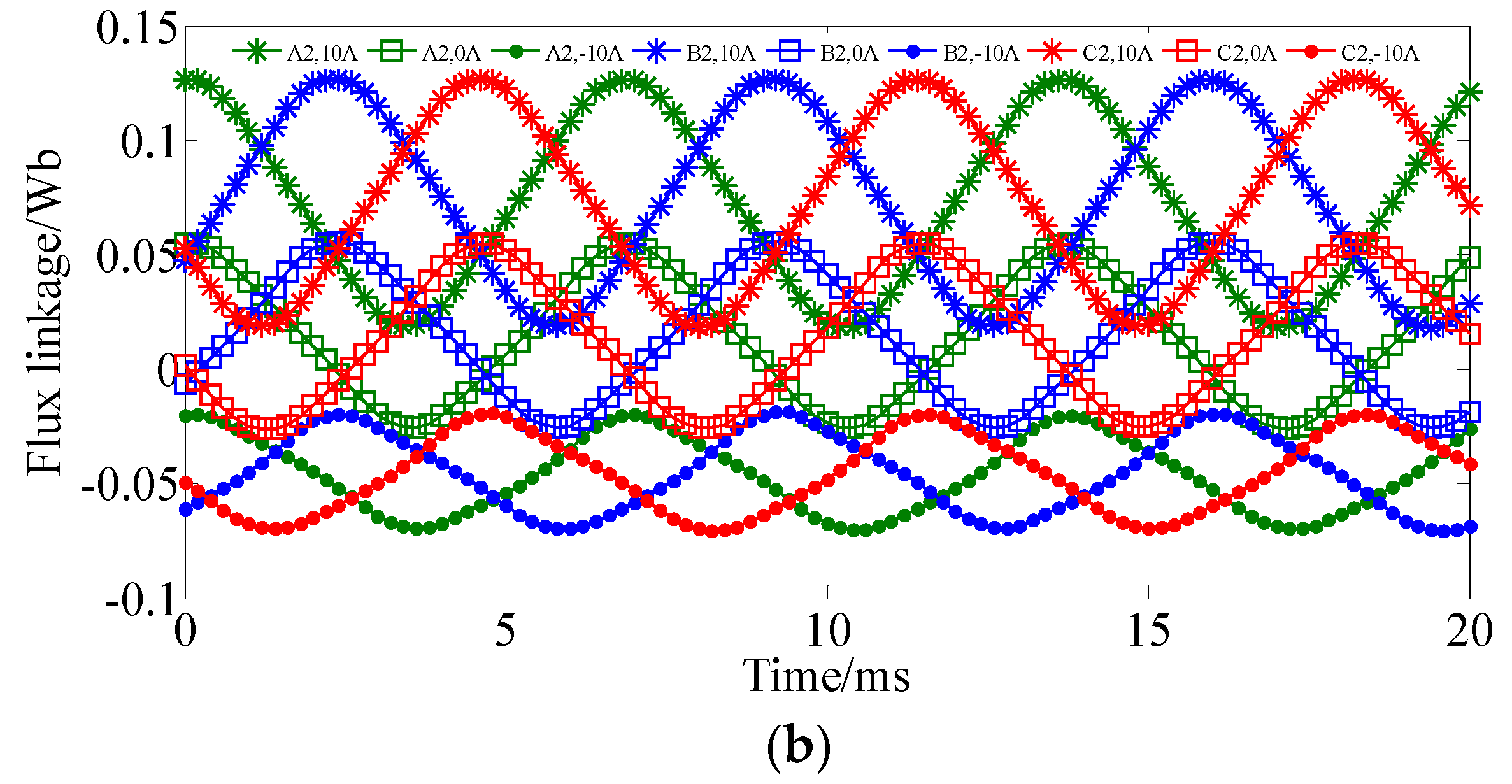
Figure 8 shows the no-load flux linkage waveforms when the machine speed is 800 r/min. The flux linkage waveforms of the two sub-phases are investigated separately. One can see that the flux linkage of the two sub-phases are synchronous but with opposite DC bias components. The peak-peak value of flux linkage increases when the DC bias current is positive, which corresponds to the flux strengthening stage. When applied with negative DC bias current, the peak-peak value of the flux linkage decreases, which corresponds to the flux weakening process. In a traditional synchronous machine, flux linkage has no DC bias component. However, in our proposed machine, the rotor permanent magnet field can generate a stationary harmonic with six pole-pairs caused by the flux modulating effect. This 6-pole-pair harmonic will produce DC bias flux linkage and share the same magnetic path as the DC bias current.
Figure 9 gives the back-EMF waveforms when the machine speed is 800 r/min, the corresponding machine frequency is 147 Hz. One can see that the back EMF can be strengthened and weakened efficiently by the DC bias current. It should be noted that the DC bias component in the flux linkage has no influence on the back EMF because the differential of DC bias flux linkage is zero and the EMF is determined by the variation of the flux linkage. Although sub-phase one and sub-phase two have opposite DC bias flux linkage components, their back EMF waveforms are coincident.
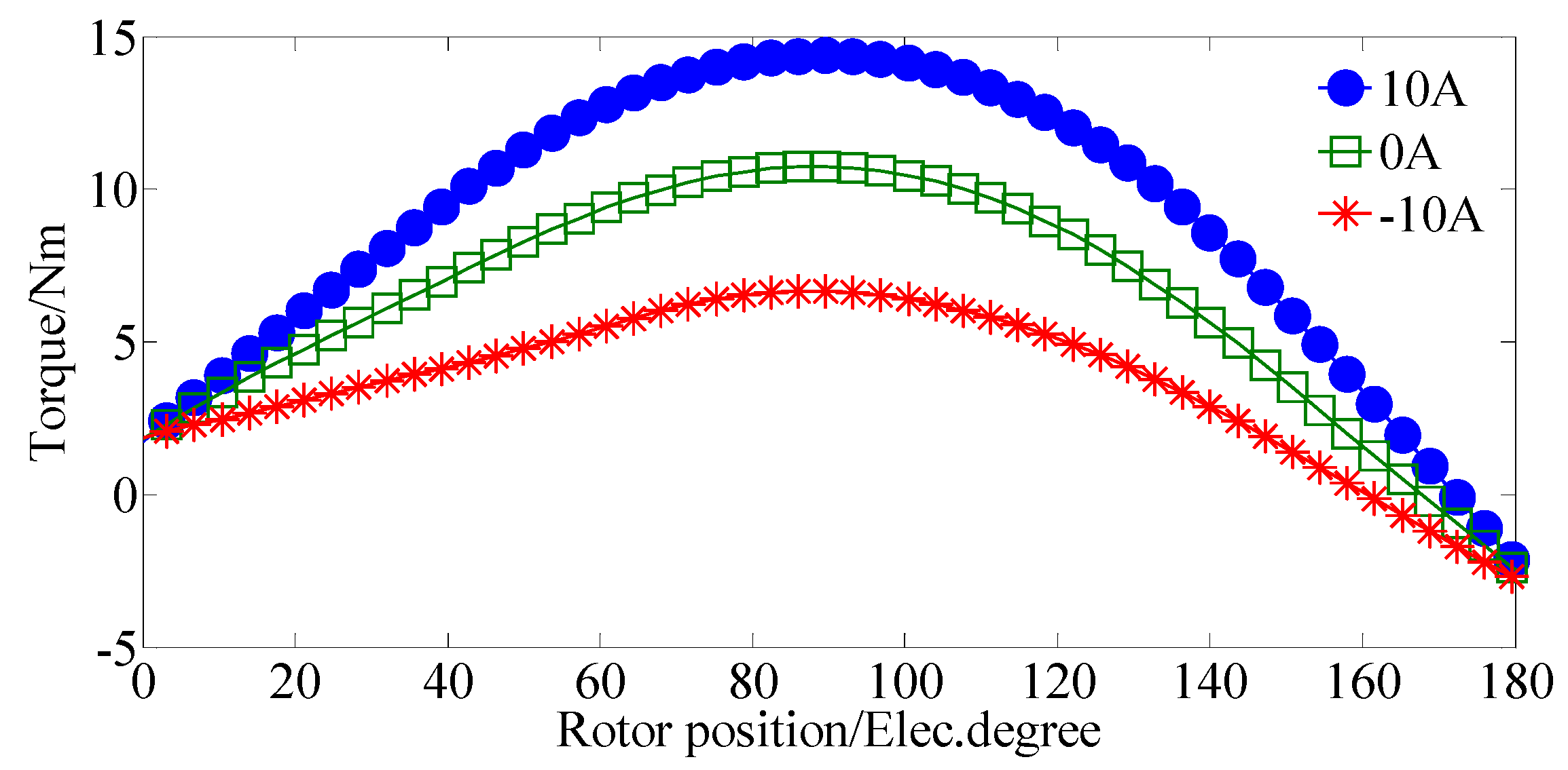
The stationary torque is calculated and given in Figure 10, when the armature current density is 8 A/mm2. Again, we can see that the output torque can be adjusted by controlling the DC bias current. For the driving machine in electric vehicles, the maximum current density can be around 22 A/mm2 when a liquid cooling system is used. However, this maximum current density can only be applied for a very short period since huge heat will be generated by the large copper loss. Definitely, copper loss and temperature will increase when the current density is 22 A/mm2, and the efficiency will be reduced. The output torque and torque per PM volume (T/PMV) of the proposed DCF-HEM are given in Figure 11. In this case, no DC bias current is applied and the winding current only has an AC component which is used to generate electromagnetic torque. The maximum T/PMV reaches 594 kN·m/m3 when the armature current density is 22 A/mm2. The electromagnetic performances of the proposed DCF-HEM are summarized in Table 3.
5. Experimental Validation
The prototype of the proposed DCF-HEM was manufactured with the same parameters as given in Table 1. Figure 12 shows the experimental test bench. All the coils are brought out and connected outside the machine. The windings of the two sub-phases are connected separately, and each sub-phase is controlled by a converter. A 1.5 kW servo machine connected to a Siemens 1212C PLC controller (SIMENS, München, Germany) is used to provide adjustable load torque. Torque sensor is used to test the electromagnetic torque, and an oscilloscope is used to display the tested waveforms.
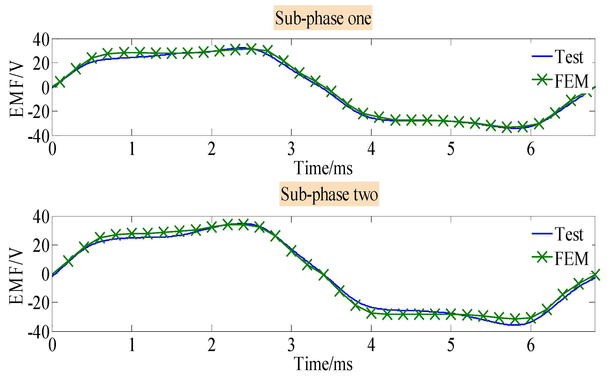
First, the back-EMF waveforms when the machine speed is 800 r/min are measured, as given in Figure 13. Since each phase has two sub-phases, the back EMF waveforms of both sub-phase windings are measured. A good match between the measured results and the simulated ones can be observed. Figure 14 shows the stationary torque waveforms, when the machine is applied with 8 A RMS AC current without DC bias. The corresponding current density is 8 A/mm2 since the cross-sectional area of the stator coil is 1 mm2. Again, there is good agreement between the results of the experimental tests and simulation. The measured torque density is 21 kNm/m3 innatural cooling conditions.
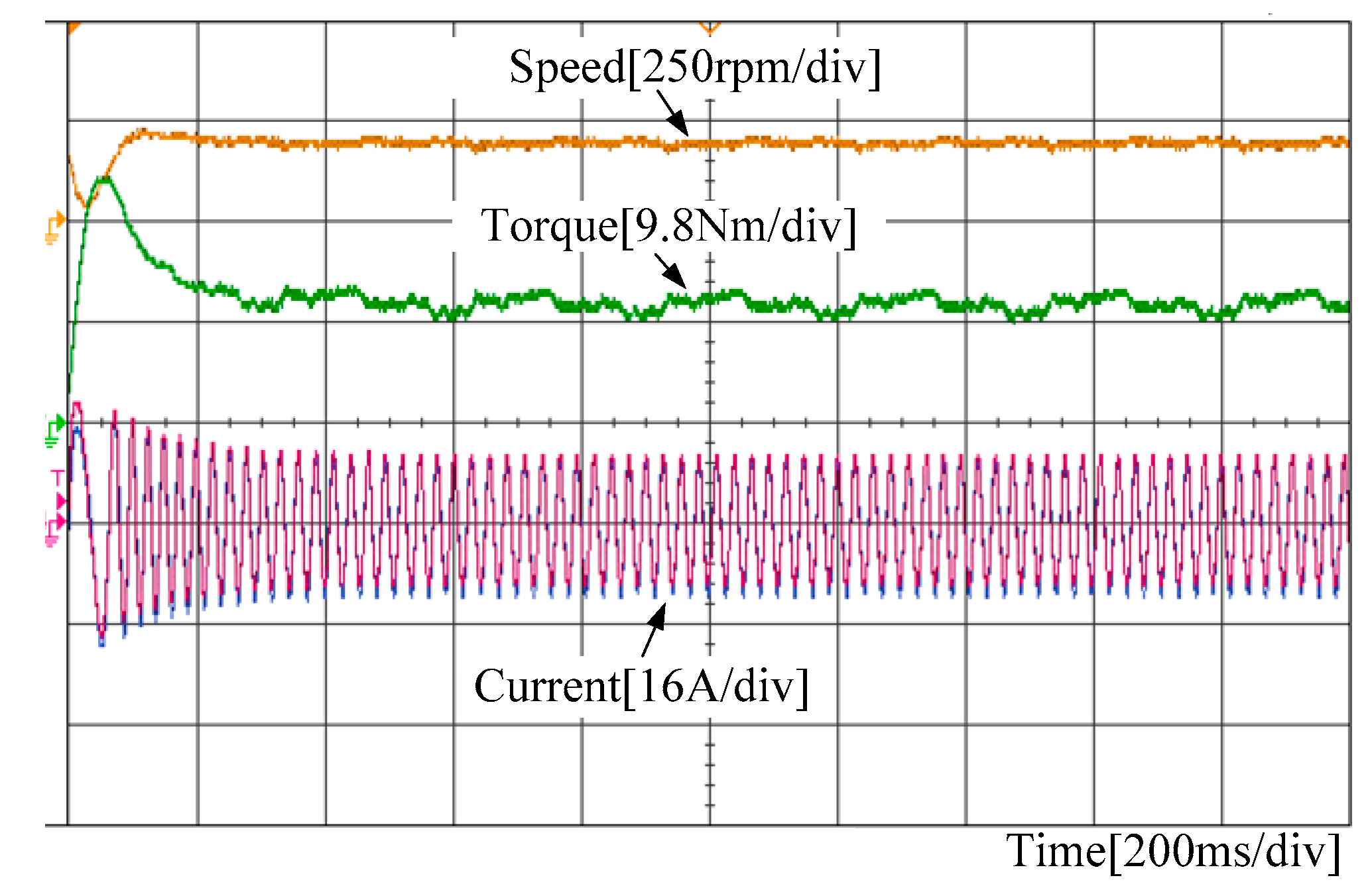
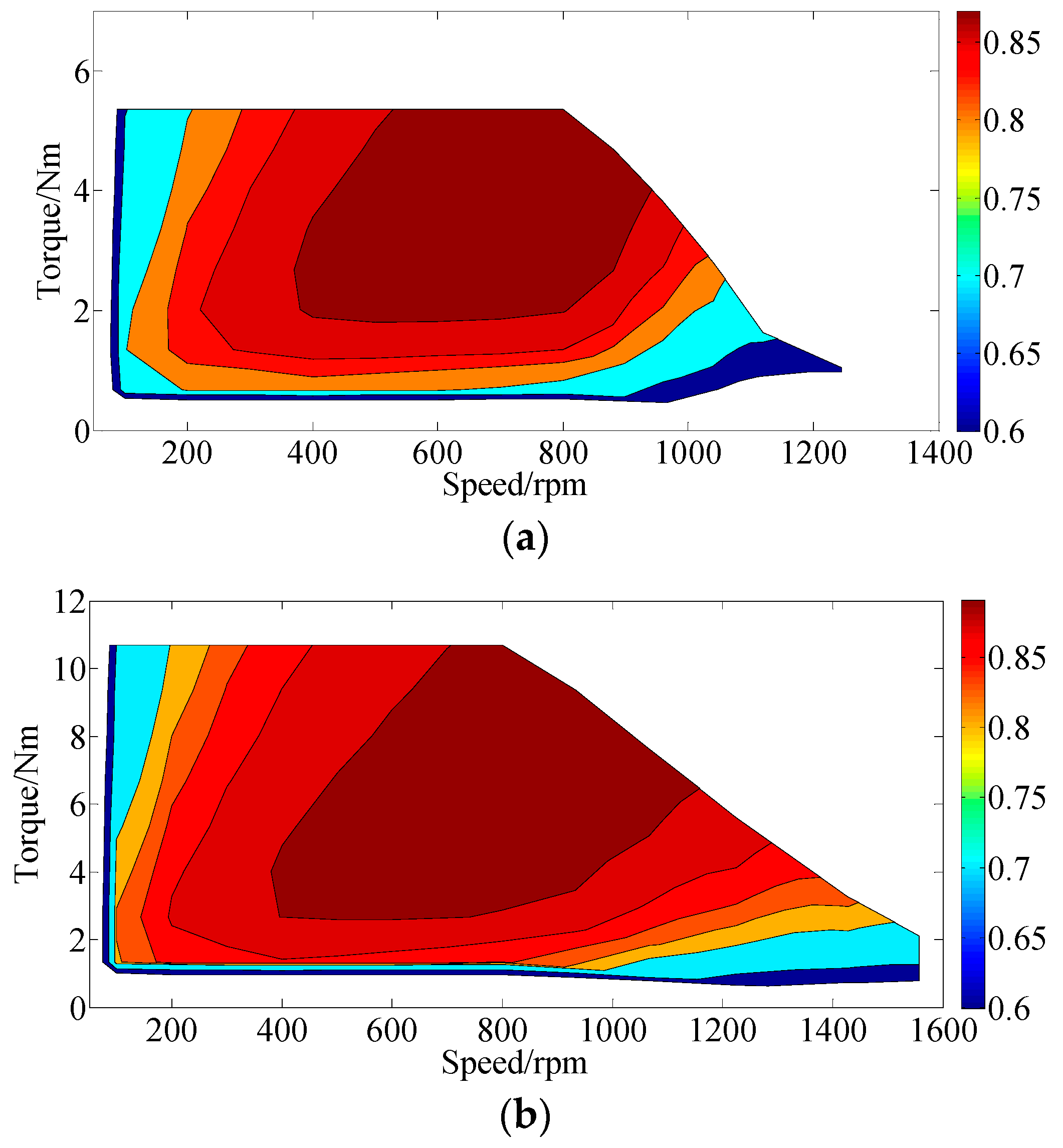
Figure 15 shows the transient waveforms of the phase current, electromagnet torque, and rotating speed when the proposed machine starts up from the stationary condition to 200 r/min. The load torque is 10 N·m, which is provided by the servo machine. Although the mechanical characteristics were not investigated, it can be observed from Figure 15 that the proposed DCF-HEM can reach steady state condition within 200 ms, which shows good dynamic performances. The efficiency map of the proposed machine over the whole operating region was investigated, and compared with the efficiency when using external DC field current control as used in traditional hybrid excited machines, as given in Figure 16. It can be seen that the proposed DCF-HEM can achieve both higher torque and a wider flux weakening range. It should be noted that there is a tradeoff between the torque density and flux weakening range. If we reduce the permanent magnet excitation, the flux weakening capability can be improved but the torque density will be reduced.
6. Conclusions
A novel DCF-HEM with PM-iron consequent-pole rotor is proposed in this paper. DC coils in traditional HEMs are eliminated in the proposed design, and DC bias current is injected into the excitation to achieve flux regulation. Compared with traditional HEMs, the proposed DCF-HEM can be designed with a higher torque capability and a wider flux regulating range. The proposed machine has good potential in electric traction applications.
Acknowledgments
This work was supported in part by the Research Grant Council, Hong Kong Special Administrative Region under project PolyU15250916/16E and in part by the National Natural Science Foundation of China under Project 51707171.
Author Contributions
Shuangxia Niu conceived the idea of the research and provided guidance and supervision. Qingsong Wang implemented the research, performed the analysis, and wrote the paper. All authors contributed significantly to this work.
Conflicts of Interest
The authors declare no conflict of interest.
References
- Cao, W.; Mecrow, B.C.; Atkinson, G.J.; Bennett, J.W.; Atkinson, D.J. Overview of Electric Motor Technologies Used for More Electric Aircraft (MEA). IEEE Trans. Ind. Electron. 2012, 59, 3523–3531. [Google Scholar]
- Wang, Q.; Niu, S. Electromagnetic Design and Analysis of a Novel Fault-Tolerant Flux-Modulated Memory Machine. Energies 2015, 8, 8069–8085. [Google Scholar] [CrossRef]
- Chau, K.T.; Chan, C.C.; Liu, C. Overview of permanent-magnet brushless drives for electric and hybrid electric vehicles. IEEE Trans. Ind. Electron. 2008, 55, 2246–2257. [Google Scholar] [CrossRef] [Green Version]
- Chen, G.R.; Yang, S.C.; Hsu, Y.L.; Li, K. Position and Speed Estimation of Permanent Magnet Machine Sensorless Drive at High Speed Using an Improved Phase-Locked Loop. Energies 2017, 10, 1571. [Google Scholar] [CrossRef]
- Kim, S.I.; Park, S.; Park, T.; Cho, J.; Kim, W.; Lim, S. Investigation and Experimental Verification of a Novel Spoke-Type Ferrite-Magnet Motor for Electric-Vehicle Traction Drive Applications. IEEE Trans. Ind. Electron. 2014, 61, 5763–5770. [Google Scholar]
- Kappatou, J.C.; Zalokostas, G.D.; Spyratos, D.A. 3-D FEM Analysis, Prototyping and Tests of an Axial Flux Permanent-Magnet Wind Generator. Energies 2017, 10, 1269. [Google Scholar] [CrossRef]
- Wang, Q.; Niu, S.; Yang, S. Design optimization and comparative study of novel magnetic-geared permanent magnet machines. IEEE Trans. Magn. 2017, 53, 1–4. [Google Scholar] [CrossRef]
- Kwon, T.-S.; Choi, G.-Y.; Kwak, M.-S.; Sul, S.-K. Novel flux-weakening control of an IPMSM for quasi-six-step operation. IEEE Trans. Ind. Appl. 2008, 44, 1722–1731. [Google Scholar] [CrossRef]
- Tursini, M.; Chiricozzi, E.; Petrella, R. Feedforward flux-weakening control of surface-mounted permanent-magnet synchronous motors accounting for resistive voltage drop. IEEE Trans. Ind. Electron. 2010, 57, 440–448. [Google Scholar] [CrossRef]
- Wang, Q.; Niu, S. Overview of flux-controllable machines: Electrically excited machines, hybrid excited machines and memory machines. Renew. Sustain. Energy Rev. 2017, 68, 475–491. [Google Scholar] [CrossRef]
- Xiaoyong, Z.; Ming, C.; Wenxiang, Z.; Chunhua, L.; Chau, K.T. A Transient Cosimulation Approach to Performance Analysis of Hybrid Excited Doubly Salient Machine Considering Indirect Field-Circuit Coupling. IEEE Trans. Magn. 2007, 43, 2558–2560. [Google Scholar] [Green Version]
- Wang, Q.; Niu, S. A Novel Hybrid-Excited Flux Bidirectional Modulated Machine for Electric Vehicle Propulsion. In Proceedings of the 2016 IEEE Vehicle Power and Propulsion Conference (VPPC), Hangzhou, China, 17–20 October 2016; pp. 1–6. [Google Scholar]
- Dupas, A.; Hlioui, S.; Hoang, E.; Gabsi, M.; Lecrivain, M. Investigation of a New Topology of Hybrid-Excited Flux-Switching Machine with Static Global Winding: Experiments and Modeling. IEEE Trans. Ind. Appl. 2016, 52, 1413–1421. [Google Scholar] [CrossRef]
- Hua, H.; Zhu, Z.Q.; Zhan, H. Novel Consequent-Pole Hybrid Excited Machine with Separated Excitation Stator. IEEE Trans. Ind. Electron. 2016, 63, 4718–4728. [Google Scholar] [CrossRef]
- Liu, C.; Chau, K.T.; Zhang, X. An Efficient Wind–Photovoltaic Hybrid Generation System Using Doubly Excited Permanent-Magnet Brushless Machine. IEEE Trans. Ind. Electron. 2010, 57, 831–839. [Google Scholar] [Green Version]
- Yang, H.; Zhu, Z.Q.; Lin, H.; Zhan, H.L.; Hua, H.; Zhuang, E.; Fang, S.; Huang, Y. Hybrid-Excited Switched-Flux Hybrid Magnet Memory Machines. IEEE Trans. Magn. 2016, 52, 1–15. [Google Scholar] [CrossRef]
- Wang, Q.; Niu, S. A Novel Hybrid-Excited Dual-PM Machine with Bidirectional Flux Modulation. IEEE Trans. Energy Convers. 2017, 32, 424–435. [Google Scholar] [CrossRef]
- Amara, Y.; Vido, L.; Gabsi, M.; Hoang, E.; Ahmed, A.H.B.; Lecrivain, M. Hybrid Excitation Synchronous Machines: Energy-Efficient Solution for Vehicles Propulsion. IEEE Trans. Veh. Technol. 2009, 58, 2137–2149. [Google Scholar] [CrossRef]
- Chen, J.T.; Zhu, Z.Q.; Iwasaki, S.; Deodhar, R. A novel hybrid excited flux-switching brushless AC Machines for EV/HEV applications. In Proceedings of the 2010 IEEE Vehicle Power and Propulsion Conference, Lille, France, 1–3 September 2010; pp. 1–6. [Google Scholar]
- Leuzzi, R.; Li, Y.; Sarlioglu, B. Performance evaluation of a hybrid-excited flux-switching PM motor for traction applications. In Proceedings of the IECON 2016—42nd Annual Conference of the IEEE Industrial Electronics Society, Florence, Italy, 23–26 October 2016; pp. 1846–1851. [Google Scholar]
- Palka, R.; Bonislawski, M.; Holub, M. Machine and inverter loss minimization of hybrid excited permanent magnet synchronous machines for electric vehicles. In Proceedings of the 2016 Progress in Electromagnetic Research Symposium (PIERS), Shanghai, China, 8–11 August 2016; pp. 4356–4360. [Google Scholar]
- Patin, N.; Vido, L.; Monmasson, E.; Louis, J.P.; Gabsi, M.; Lecrivain, M. Control of a Hybrid Excitation Synchronous Generator for Aircraft Applications. IEEE Trans. Ind. Electron. 2008, 55, 3772–3783. [Google Scholar] [CrossRef]
- Fodorean, D.; Szabo, L.; Miraoui, A. Generator solutions for stand alone pico-electric power plants. In Proceedings of the 2009 IEEE International Electric Machines and Drives Conference, Miami, FL, USA, 3–6 May 2009; pp. 434–438. [Google Scholar]
- Tapia, J.A.; Leonardi, F.; Lipo, T.A. Consequent-pole permanent-magnet machine with extended field-weakening capability. IEEE Trans. Ind. Appl. 2003, 39, 1704–1709. [Google Scholar] [CrossRef]
- Chunhua, L.; Jin, Z.; Chau, K.T. A Novel Flux-Controllable Vernier Permanent-Magnet Machine. IEEE Trans. Magn. 2011, 47, 4238–4241. [Google Scholar] [Green Version]
- Ibala, A.; Masmoudi, A. Accounting for the Armature Magnetic Reaction and Saturation Effects in the Reluctance Model of a New Concept of Claw-Pole Alternator. IEEE Trans. Magn. 2010, 46, 3955–3961. [Google Scholar] [CrossRef]
- Xiaoyong, Z.; Ming, C.; Wei, H.; Jianzhong, Z.; Wenxiang, Z. Design and Analysis of a New Hybrid Excited Doubly Salient Machine Capable of Field Control. In Proceedings of the Conference Record of the 2006 IEEE Industry Applications Conference, 41st IAS Annual Meeting, Tampa, FL, USA, 8–12 October 2006; pp. 2382–2389. [Google Scholar]
- Chau, K.T.; Jiang, J.Z.; Yong, W. A novel stator doubly fed doubly salient permanent magnet brushless machine. IEEE Trans. Magn. 2003, 39, 3001–3003. [Google Scholar] [CrossRef] [Green Version]
- Zhihui, C.; Bo, W.; Zhe, C.; Yangguang, Y. Comparison of Flux Regulation Ability of the Hybrid Excitation Doubly Salient Machines. IEEE Trans. Ind. Electron. 2014, 61, 3155–3166. [Google Scholar]
- Wu, Z.; Zhu, Z. Analysis of air-gap field modulation and magnetic gearing effects in switched flux permanent magnet machines. IEEE Trans. Magn. 2015, 51, 1–12. [Google Scholar] [CrossRef]
- Ho, S.L.; Shiyou, Y.; Guangzheng, N.; Wong, H.C. An improved Tabu search for the global optimizations of electromagnetic devices. IEEE Trans. Magn. 2001, 37, 3570–3574. [Google Scholar] [CrossRef]
- Lei, G.; Liu, C.C.; Guo, Y.G.; Zhu, J.G. Multidisciplinary Design Analysis and Optimization of a PM Transverse Flux Machine with Soft Magnetic Composite Core. IEEE Trans. Magn. 2015, 51, 1–4. [Google Scholar] [CrossRef]
- Lei, G.; Wang, T.; Guo, Y.; Zhu, J.; Wang, S. System-Level Design Optimization Methods for Electrical Drive Systems: Deterministic Approach. IEEE Trans. Ind. Electron. 2014, 61, 6591–6602. [Google Scholar] [CrossRef]
Figure 1.
Machine Configurations. (a) The proposed DC-coil-free hybrid excited machine (DCF-HEM). (b) Connected with additional DC windings.
Figure 1.
Machine Configurations. (a) The proposed DC-coil-free hybrid excited machine (DCF-HEM). (b) Connected with additional DC windings.

Figure 2.
Flowchart of the optimization process.

Figure 3.
Optimization results of average torque and efficiency.
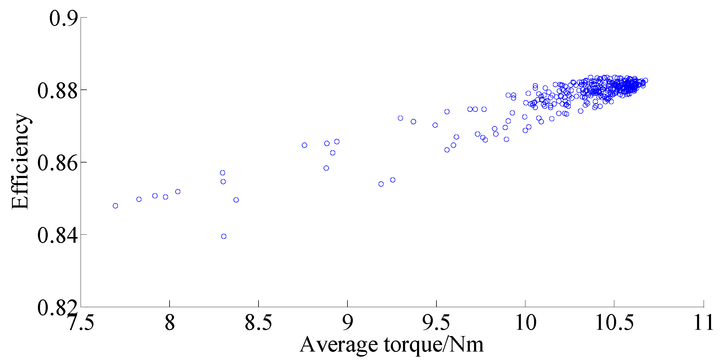
Figure 4.
Optimization results of average torque and torque ripple.

Figure 5.
Three-objective Pareto results.

Figure 6.
Results of single-objective optimization.
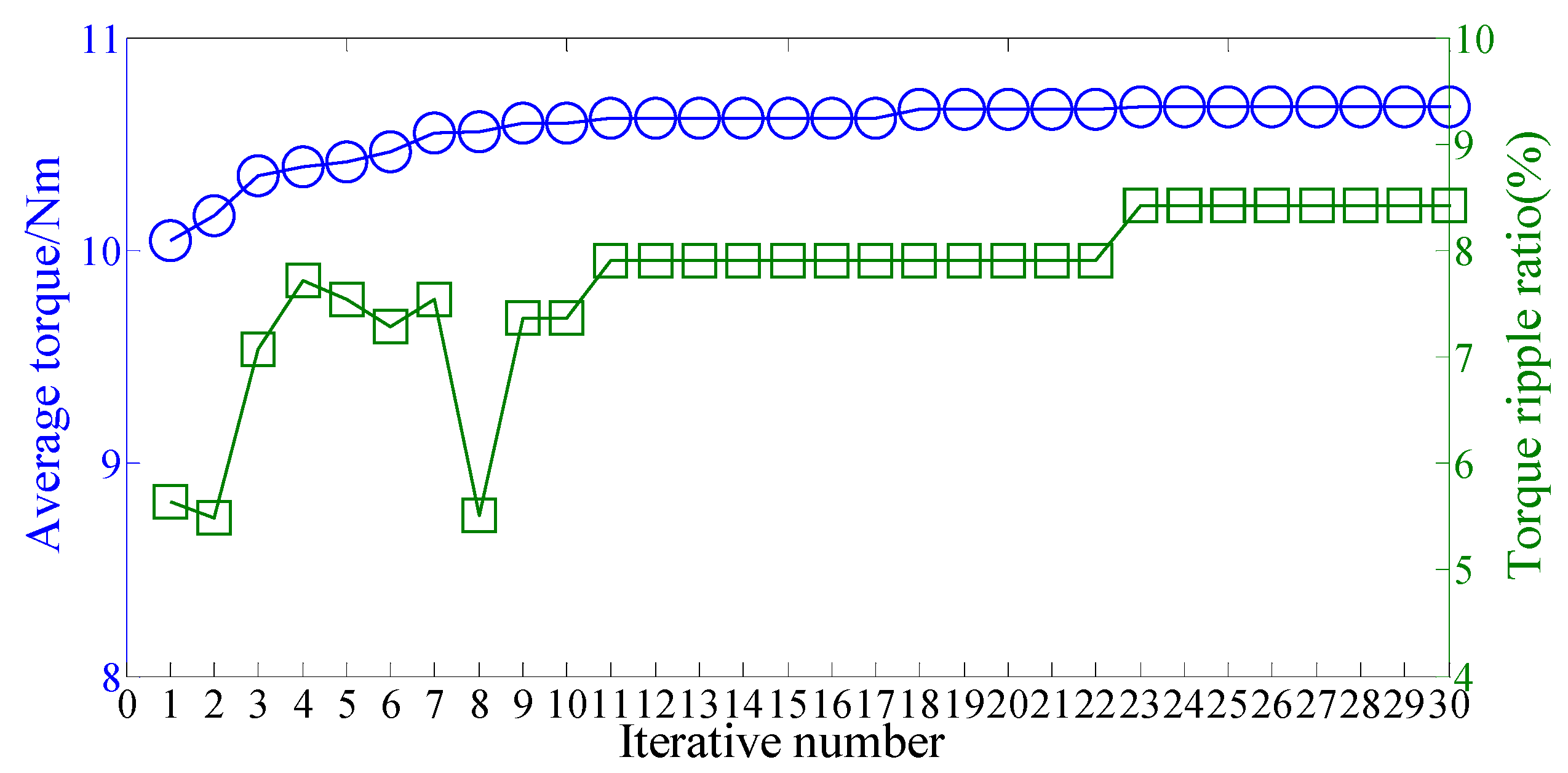
Figure 7.
No-load air-gap flux density distributions and harmonics. (a) Flux density distributions. (b) Harmonics.
Figure 7.
No-load air-gap flux density distributions and harmonics. (a) Flux density distributions. (b) Harmonics.

Figure 8.
No load flux linkage waveforms. (a) Sub-phase one. (b) Sub-phase two.
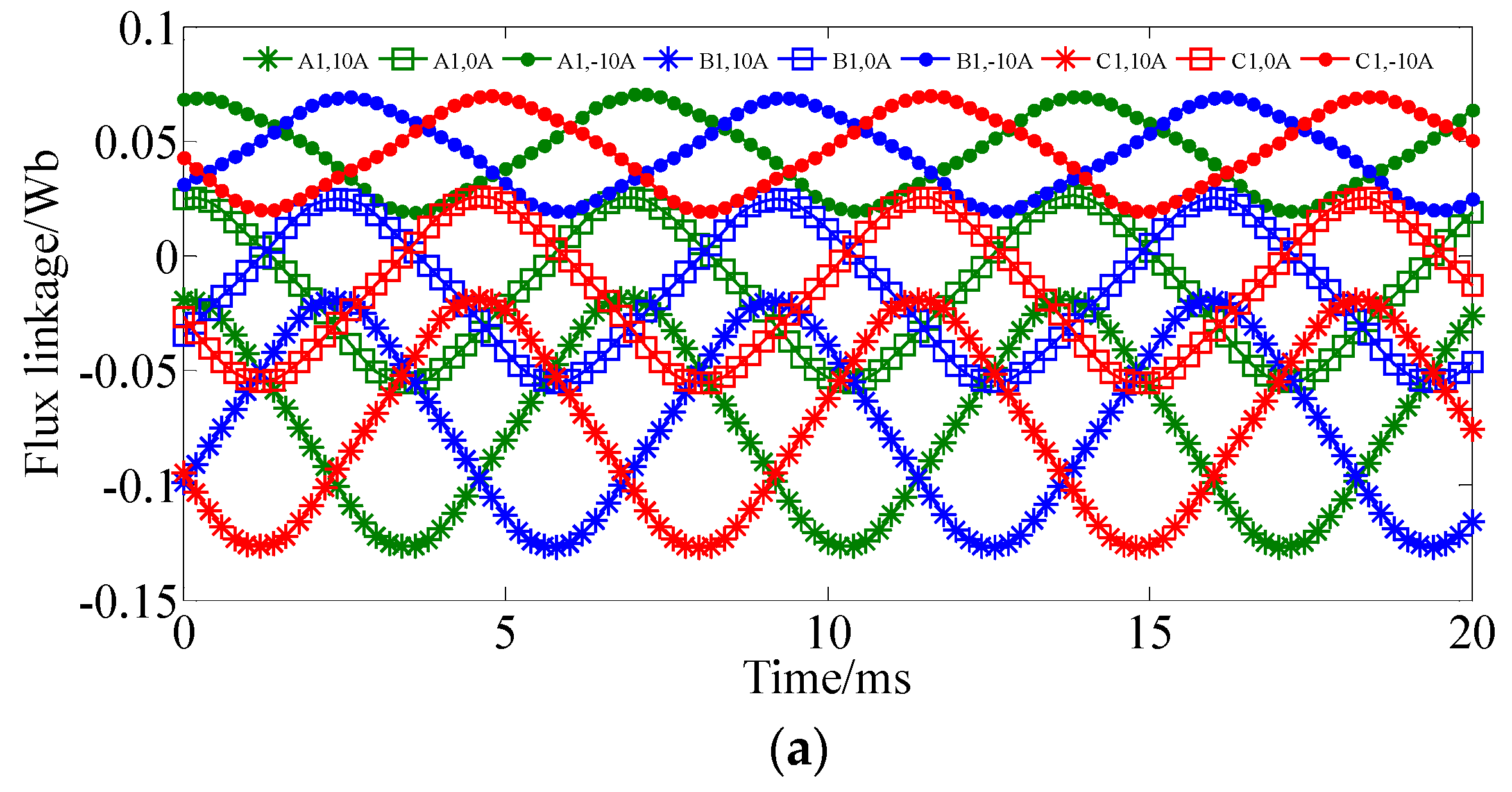

Figure 9.
Back EMF waveforms.
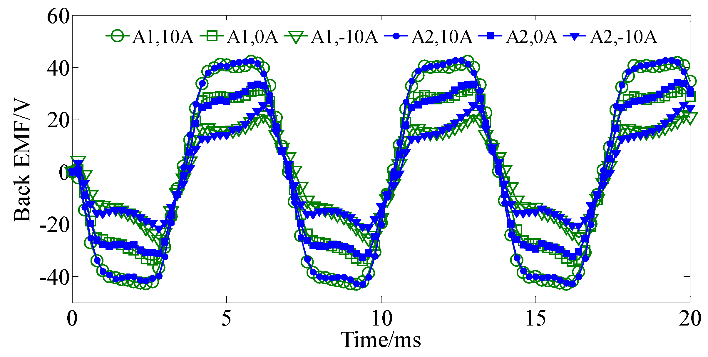
Figure 10.
Stationary torque waveforms.

Figure 11.
Output torque and T/PMV when applied with different current densities.
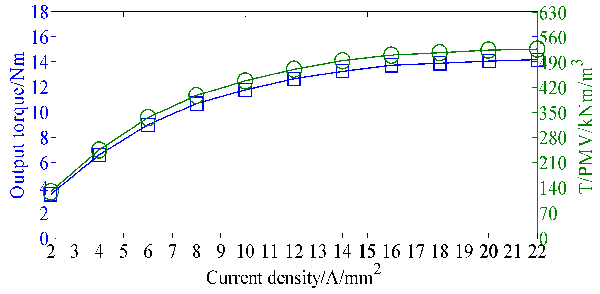
Figure 12.
Test bench of the proposed DCF-HEM.
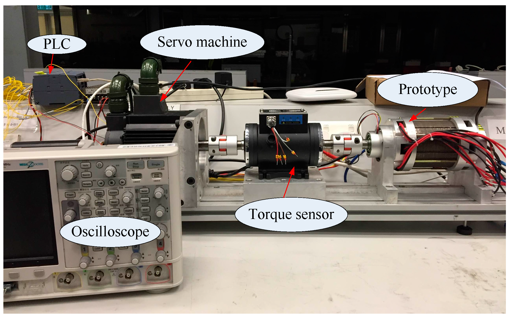
Figure 13.
Back EMF waveforms.

Figure 14.
Stationary torque waveforms.
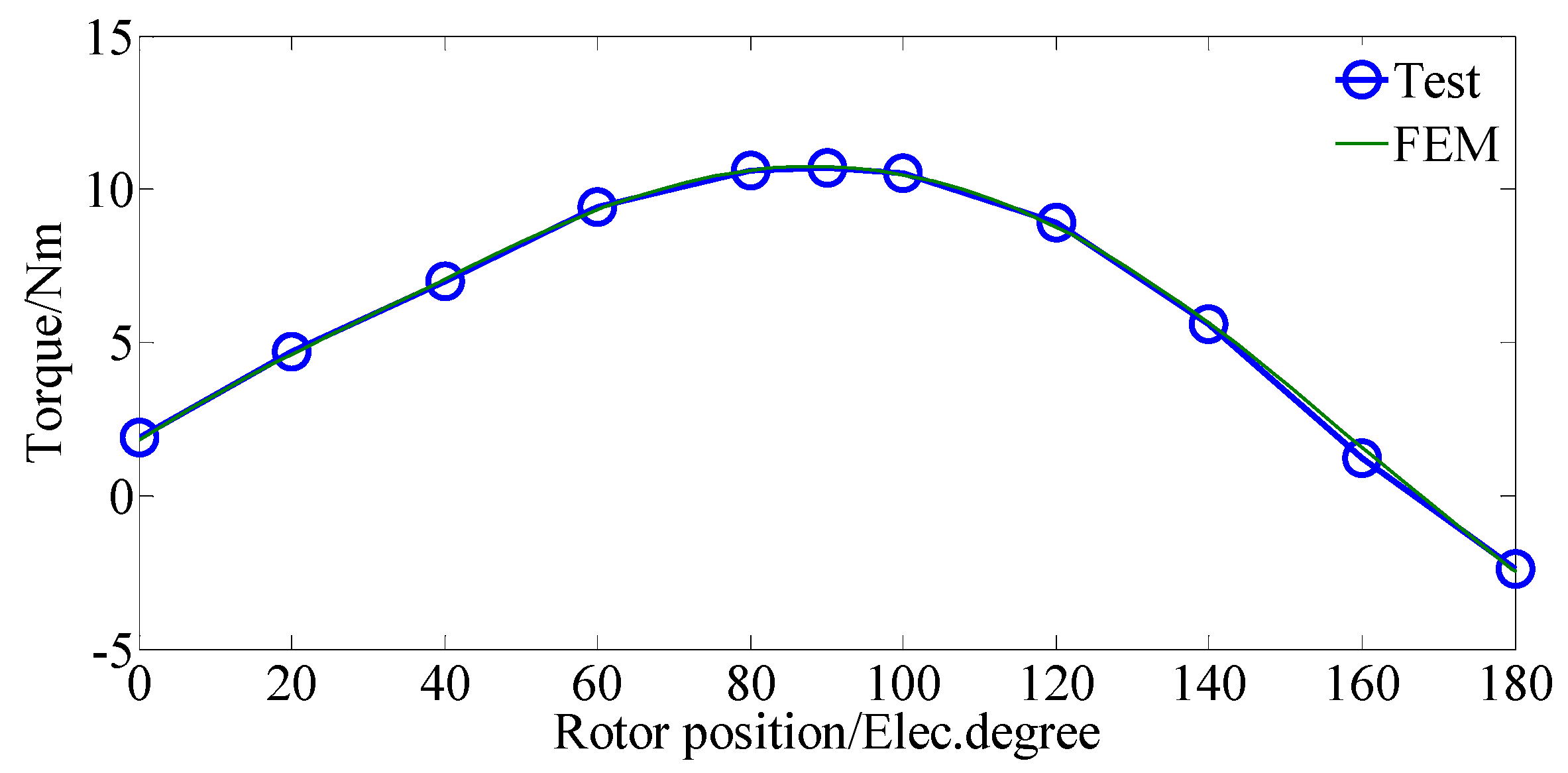
Figure 15.
Measured transient waveforms during start-up process.

Figure 16.
Efficiency maps. (a) External DC field current control. (b) DC bias current control.


Table 1.
Optimized parameters and their limits. DCF-HEM: DC-coil-free-hybrid excited machines; PM: permanent magnet.
Table 1.
Optimized parameters and their limits. DCF-HEM: DC-coil-free-hybrid excited machines; PM: permanent magnet.
| Parameters | DCF-HEM | |
|---|---|---|
| Upper Limit | Lower Limit | |
| Inner diameter of stator (mm) | 64 | 55 |
| Rotor PM ratio | 80% | 30% |
| Thickness of rotor PM (mm) | 5 | 2 |
| Width of stator teeth (mm) | 8 | 5 |
| Height difference of stator teeth (mm) | 5 | 2 |
Table 2.
Design parameters.
| Parameters | Initial Value | Optimized Value |
|---|---|---|
| Outer diameter of stator (mm) | 90 | |
| Inner diameter of stator (mm) | 56 | 58.8 |
| Outer diameter of rotor (mm) | 55 | 57.8 |
| Inner diameter of rotor (mm) | 30 | |
| Stack length (mm) | 80 | |
| Air-gap length (mm) | 0.5 | |
| Stator teeth width (mm) | 6.4 | 5.8 |
| Height difference of stator teeth (mm) | 3.2 | 2.7 |
| PPN of armature winding | 5 | |
| PPN of field winding | 6 | |
| PPN of rotor PMs | 11 | |
| Rotor PM ratio (%) | 60 | 50 |
| Rotor PM thickness (mm) | 3.5 | 4.3 |
| Number of phases | 3 | |
| Number of stator slots | 12 | |
| Relative permeability of NdFeB | 1.05 | |
| Remanence of NdFeB (T) | 1.2 | |
Table 3.
Electromagnetic performances.
| Items | Initial Value | Optimized Value |
|---|---|---|
| Rated power (W) | 745 | 896 |
| Rated speed (r/min) | 800 | |
| Rated torque (N·m) | 8.9 | 10.7 |
| Peak torque (N·m) | 11.9 | 14.1 |
| PM usage (cm3) | 22.64 | 26.8 |
| Torque density (kN·m/m3) | 23.6 | 28 |
| T/PMV (kN·m/m3) | 526 | 594 |
© 2018 by the authors. Licensee MDPI, Basel, Switzerland. This article is an open access article distributed under the terms and conditions of the Creative Commons Attribution (CC BY) license (http://creativecommons.org/licenses/by/4.0/).
Share and Cite
MDPI and ACS Style
Wang, Q.; Niu, S. A Novel DC-Coil-Free Hybrid-Excited Machine with Consequent-Pole PM Rotor. Energies 2018, 11, 700. https://doi.org/10.3390/en11040700
AMA Style
Wang Q, Niu S. A Novel DC-Coil-Free Hybrid-Excited Machine with Consequent-Pole PM Rotor. Energies. 2018; 11(4):700. https://doi.org/10.3390/en11040700
Chicago/Turabian StyleWang, Qingsong, and Shuangxia Niu. 2018. "A Novel DC-Coil-Free Hybrid-Excited Machine with Consequent-Pole PM Rotor" Energies 11, no. 4: 700. https://doi.org/10.3390/en11040700
Note that from the first issue of 2016, this journal uses article numbers instead of page numbers. See further details here.