Assessment of the Induced Electric Fields in a Carbon-Fiber Electrical Vehicle Equipped with a Wireless Power Transfer System


Abstract
:1. Introduction
2. Models and Methods
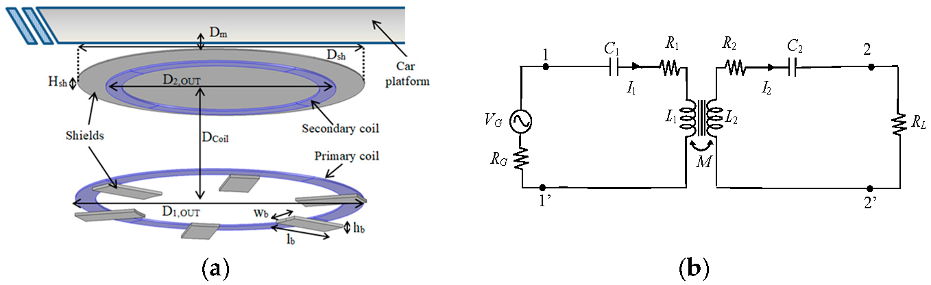
2.1. WPT System Configuration
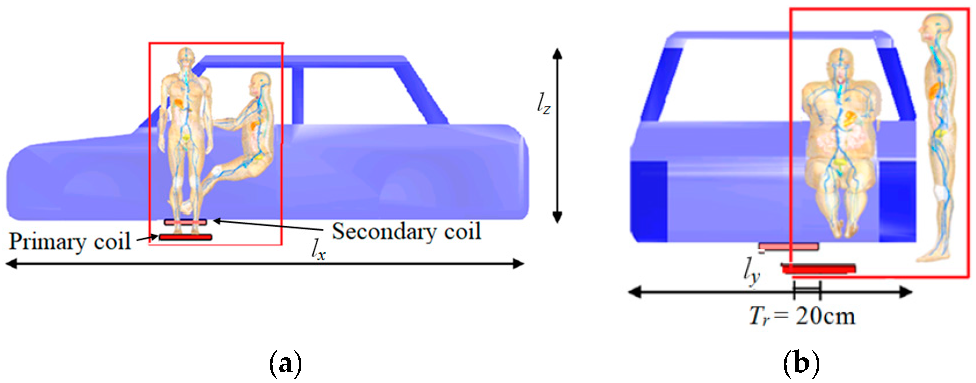
2.2. EV, Human Body Models, and Exposure Scenario
- (1)
- CF composite panels (d = 2 mm, σ = 100 S/m);
- (2)
- steel panels (d = 1.2 mm, σ = 107 S/m);
- (3)
- aluminum panels (d = 2 mm, σ = 3 × 10⁷ S/m).
2.3. External Magnetic Field Calculation
2.4. Internal Electric Field Calculation
3. Results
3.1. WPT Circuit Model
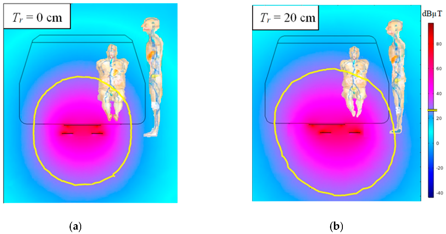
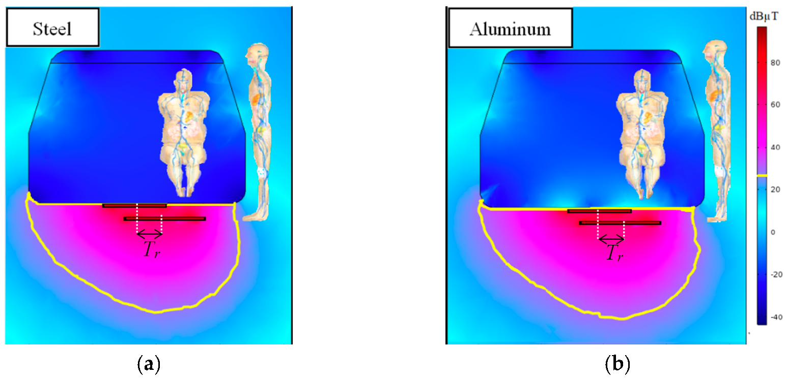
3.2. External Magnetic Field
3.3. Induced Electric Field
4. Conclusions
Acknowledgments
Author Contributions
Conflicts of Interest
Founding
References
- Covic, G.A.; Boys, J.T. Inductive power transfer. Proc. IEEE 2013, 101, 1276–1289. [Google Scholar] [CrossRef]
- Shinohara, N. Power without wires. IEEE Microw. Mag. 2011, 11, 64–73. [Google Scholar] [CrossRef]
- International Commission on Non-Ionizing Radiation Protection. Guidelines for limiting exposure to time-varying electric and magnetic fields for low frequencies (1 Hz–100 kHz). Health Phys. 2010, 99, 818–836. [Google Scholar]
- IEEE Std. C95.1-2005, IEEE Standard for Safety Levels with Respect to Human Exposure to Radio Frequency Electromagnetic Fields, 3 kHz to 300 GHz; IEEE: New York, NY, USA, 2006; pp. 1–238. [Google Scholar]
- Cimala, C.; Clemens, M.; Streckert, J.; Schmuelling, B. High-resolution magnetic-field exposure simulations of automotive inductive power-transfer systems using a scaled-frequency finite difference time domain approach with multi-GPU acceleration. Int. J. Numer. Model 2017, e2231, 1–5. [Google Scholar] [CrossRef]
- Sunohara, T.; Hirata, A.; Laakso, I.; Onishi, T. Analysis of in situ electric field and specific absorption rate in human models for wireless power transfer system with induction coupling. Phys. Med. Biol. 2014, 59, 3721–3735. [Google Scholar] [CrossRef] [PubMed]
- Shimamoto, T.; Laakso, I.; Hirata, A. In-situ electric field in human body model in different postures for wireless power transfer system in an electrical vehicle. Phys. Med. Biol. 2015, 60, 163–173. [Google Scholar] [CrossRef] [PubMed]
- Chakarothai, J.; Wake, K.; Arima, T.; Watanabe, S.; Uno, T. Exposure evaluation of an actual Wireless Power Transfer system for an electric vehicle with near-field measurement. IEEE Trans. Microw. Theory Tech. 2018, 66, 1543–1552. [Google Scholar] [CrossRef]
- Park, S. Evaluation of Electromagnetic Exposure during 85 kHz Wireless Power Transfer for Electric Vehicles. IEEE Trans. Magn. 2018, 54, 1–8. [Google Scholar] [CrossRef]
- Pinto, R.; Lopresto, V.; Genovese, A. Human exposure to wireless power transfer systems: A numerical dosimetric study. In Proceedings of the 11th European Conference on Antennas and Propagation (EUCAP), Paris, France, 19–24 March 2017. [Google Scholar]
- Romo, J.; Cañibano, E.; Merino, J.C. Lightweighting and passive safety for urban electric vehicle. In Proceedings of the Electric Vehicles International Conference (EV2017), Bucharest, Romania, 5–6 October 2017. [Google Scholar]
- Campi, T.; Cruciani, S.; De Santis, V.; Maradei, F.; Feliziani, M. Numerical characterization of the magnetic field in electrical vehicles equipped with a WPT system. Wirel. Power Transf. 2017, 4, 78–87. [Google Scholar] [CrossRef]
- Campi, T.; Cruciani, S.; De Santis, V.; Maradei, F.; Feliziani, M. Magnetic field behavior in a carbon-fiber Electrical Vehicle charged by a Wireless Power Transfer system. In Proceedings of the 2017 IEEE International Symposium on Electromagnetic Compatibility (EMC), Angers, France, 4–8 September 2017. [Google Scholar]
- IEC 61980-1. Electric Vehicle Wireless Power Transfer (WPT) Systems—Part 1: General Requirements; International Electrotechnical Commission: Geneva Switzerland, 2015. [Google Scholar]
- SAE TIR J2954. Wireless Power Transfer for Light-Duty Plug-In/Electric Vehicles and Alignment Methodology; SAE International: Warrendale, PA, USA, 2016. [Google Scholar]
- Campi, T.; Cruciani, S.; De Santis, V.; Feliziani, M. EMF safety and thermal aspects in a pacemaker equipped with a Wireless Power Transfer system working at low frequency. IEEE Trans. Microw. Theory Tech. 2016, 64, 375–382. [Google Scholar] [CrossRef]
- Campi, T.; Cruciani, S.; Maradei, F.; Feliziani, M. Near field reduction in a Wireless Power Transfer System using LCC compensation. IEEE Trans. Electromagn. Compat. 2017, 59, 686–694. [Google Scholar] [CrossRef]
- Cruciani, S.; Campi, T.; Feliziani, M.; Maradei, F. Optimum coil configuration of wireless power transfer system in presence of shields. In Proceedings of the 2015 IEEE International Symposium on Electromagnetic Compatibility (EMC), Dresden, Germany, 16–22 August 2015; pp. 720–725. [Google Scholar]
- Gosselin, M.C.; Neufeld, E.; Moser, H.; Huber, E.; Farcito, S.; Gerber, L.; Jedensjö, M.; Hilber, I.; Di Gennaro, F.; Lloyd, B.; et al. Development of a new generation of high-resolution anatomical models for medical device evaluation: The Virtual Population 3.0. Phys. Med. Biol. 2014, 59, 5287–5303. [Google Scholar] [CrossRef] [PubMed]
- Hasgall, P.A.; Di Gennaro, F.; Baumgartner, C.; Neufeld, E.; Gosselin, M.C.; Payne, D.; Klingenböck, A.; Kuster, N. IT’IS Database for Thermal and Electromagnetic Parameters of Biological Tissues; Version 3.0; ScienceOpen, Inc.: Boston, MA, USA, 2015. [Google Scholar]
- De Santis, V.; Chen, X.L.; Laakso, I.; Hirata, A. An equivalent skin conductivity for LF magnetic field dosimetry. Biomed. Phys. Eng. Express 2015, 1, 1–10. [Google Scholar] [CrossRef]
- De Santis, V.; Douglas, M.G.; Chen, X.L.; Kuster, N. Impact of the skin conductivity and displacement currents on LF dosimetry. In Proceedings of the 2012 IEEE International Symposium on Electromagnetic Compatibility (EMC), Rome, Italy, 4–8 September 2012. [Google Scholar]
- Sim4Life-v3.2. SIMulation 4 LIFE Science. Available online: www.zurichmedtech.com/sim4life (accessed on 15 October 2017).
- Hand, J.W. Modelling the interaction of electromagnetic fields (10 MHz–10 GHz) with the human body: Methods and applications. Phys. Med. Biol. 2008, 53, R243–R286. [Google Scholar] [CrossRef] [PubMed]
- Hirata, A.; Ito, F.; Laakso, I. Confirmation of quasi-static approximation in SAR evaluation for a wireless power transfer system. Phys. Med. Biol. 2013, 58, N241–N249. [Google Scholar] [CrossRef] [PubMed]
- Chen, X.L.; Benkler, S.; Chavannes, N.; De Santis, V.; Bakker, J.; van Rhoon, G.; Mosig, J.; Kuster, N. Analysis of human brain exposure to low-frequency magnetic fields: A numerical assessment of spatially averaged electric fields and exposure limits. Bioelectromagnetics 2013, 34, 375–384. [Google Scholar] [CrossRef] [PubMed]
- De Santis, V.; Chen, X.L. On the issues related to compliance assessment of ICNIRP 2010 basic restrictions. J. Radiat. Prot. 2014, 34, N31–N39. [Google Scholar] [CrossRef] [PubMed]
- De Santis, V.; Chen, X.L.; Cruciani, S.; Campi, T.; Feliziani, M. A novel homogenization procedure to model the skin layers in LF numerical dosimetry. Phys. Med. Biol. 2016, 61, R4402–R4411. [Google Scholar] [CrossRef] [PubMed]
- Schmid, G.; Cecil, S.; Überbacher, R. On the importance of body posture and skin modelling with respect to in situ electric field strengths in magnetic field exposure scenarios. Phys. Med. Biol. 2016, 61, 4412–4437. [Google Scholar] [CrossRef] [PubMed]
- Reilly, J.P.; Hirata, A. Low-frequency electrical dosimetry: Research agenda of the IEEE International Committee on Electromagnetic Safety. Phys. Med. Biol. 2016, 61, R138–R149. [Google Scholar] [CrossRef] [PubMed]


| Dcoil (cm) | D1,OUT (cm) | D2,OUT (cm) | Dm (cm) | lb (cm) | wb (cm) | hb (cm) | Dsh (cm) | Hsh (cm) |
|---|---|---|---|---|---|---|---|---|
| 20 | 50 | 40 | 0.8 | 9.3 | 5.8 | 0.4 | 0.5 | 0.2 |
| EV Bodyshell | L1 (µH) | L2 (µH) | M (µH) | k | I1 (A) | I2 (A) |
|---|---|---|---|---|---|---|
| Carbon fiber composite | 125.2 | 89.4 | 7.4 | 0.069 | 50.3 | 39.2 |
| Aluminum | 125.9 | 88.4 | 7.1 | 0.065 | 55.1 | 39.2 |
| Steel | 124.1 | 86.1 | 6.5 | 0.061 | 59.1 | 39.2 |
| EV Chassis | L1 (µH) | L2 (µH) | M (µH) | k | I1 (A) | I2 (A) |
|---|---|---|---|---|---|---|
| Carbon fiber composite | 124.8 | 88.2 | 7.3 | 0.070 | 26.5 | 39.2 |
| Aluminum | 124.5 | 87.3 | 7.1 | 0.068 | 29.7 | 39.2 |
| Steel | 123.5 | 85.4 | 6.4 | 0.062 | 32.5 | 39.2 |
| EV Chassis | Tr (cm) | Bmax (dBµT) Driver | Bmax (dBµT) Standing | Overexposure (dB) |
|---|---|---|---|---|
| Carbon fiber Composite | 0 | 44.6 | 18.5 | 16.0 |
| 20 | 52.8 | 32.3 | 24.2 | |
| Aluminum | 20 | −4.2 | 19.1 | / |
| Steel | 20 | −18.2 | 20.3 | / |
| Standing & Driving | Coil Position | f (kHz) | E (V/m) | BR (V/m) | Overexposure (dB) |
|---|---|---|---|---|---|
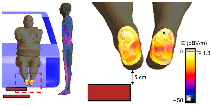
| Duke & Fats | Aligned | 85 | 13.3 | 11.4 | 1.28 |
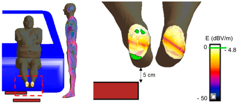
| Duke & Fats | Misaligned | 85 | 19.9 | 11.4 | 4.77 |
| Fats & Duke | Misaligned | 85 | 19.6 | 11.4 | 4.65 |
| Fats & Duke | Misaligned | 150 | 35 | 20.2 | 4.75 |
© 2018 by the authors. Licensee MDPI, Basel, Switzerland. This article is an open access article distributed under the terms and conditions of the Creative Commons Attribution (CC BY) license (http://creativecommons.org/licenses/by/4.0/).
Share and Cite
De Santis, V.; Campi, T.; Cruciani, S.; Laakso, I.; Feliziani, M. Assessment of the Induced Electric Fields in a Carbon-Fiber Electrical Vehicle Equipped with a Wireless Power Transfer System. Energies 2018, 11, 684. https://doi.org/10.3390/en11030684
De Santis V, Campi T, Cruciani S, Laakso I, Feliziani M. Assessment of the Induced Electric Fields in a Carbon-Fiber Electrical Vehicle Equipped with a Wireless Power Transfer System. Energies. 2018; 11(3):684. https://doi.org/10.3390/en11030684
Chicago/Turabian StyleDe Santis, Valerio, Tommaso Campi, Silvano Cruciani, Ilkka Laakso, and Mauro Feliziani. 2018. "Assessment of the Induced Electric Fields in a Carbon-Fiber Electrical Vehicle Equipped with a Wireless Power Transfer System" Energies 11, no. 3: 684. https://doi.org/10.3390/en11030684