1. Introduction
Growing concerns about climate change, rising costs of fossil fuel, and the geopolitical uncertainty associated with an uninterrupted energy supply have motivated individuals, organizations and nations to look for substitutes that are clean and renewable [
1,
2]. Hydrogen (H
2) is, currently, considered as one of the leading candidates in the search alternatives to fossil fuels (FF) [
3]. Nevertheless, H
2 is only an energy carrier like electricity and not a primary energy source. It can be produced from a wide variety of energy sources, such as natural gas, coal, biomass, solar (thermal and photovoltaic), etc. [
4] and act as a unique energy hub providing low or zero emission in energy use to all energy consuming sectors [
5]. However, the environmental performance of hydrogen-production systems highly depends on the type of primary energy and conversion technology used [
6]. Among several renewable energy sources, bio-hydrogen is gaining a lot of attraction because of its conversion efficiency with less pollutant generation [
7]. In particular, hydrogen production through lignocellulosic biomass residues gasification is a promising pathway in terms of global warming impacts and energy security [
8,
9,
10]. However, although lignocellulosic biomass is a renewable resource, its use does not guarantee an appropriate environmental performance [
11] and, even under strategies of using agriculture and forestry residues to avoid emissions from direct and indirect land use change, the feedstock use can potentially cause negative environmental impacts [
12]. Therefore, it is requisite to analyze entire biomass to hydrogen production process considering the impacts from the cultivation to the conversion plant.
LCA is a well-established methodology to evaluate the environmental impacts of a product over its life cycle. It is often used to determine the greenhouse gas footprint and minimum selling price in several kinds of processes and in particular regarding biomasses [
13]. This is achieved by: (i) gathering all relevant inputs and outputs of the considered system; (ii) evaluating the potential environmental impacts related to these inputs and outputs; and (iii) interpreting the results obtained in the impact assessment phase [
14]. Hence, LCA is a viable tool to identify environmental hotspots and find approaches that enhance environmental results related to the products [
15,
16]. The LCA application to energy is becoming increasingly important for evaluating which technology is more affordable and more sustainable [
17]. LCA often demonstrated the benefits of replacement of oil with bioenergy systems [
18] not only for energy but also for refinery scopes [
19]. Despite the potential role of LCA in sustainable development of energy systems [
20], few LCA studies have been carried out on H
2 production from biomass [
8,
9,
21,
22]. In these papers, agricultural and forestry waste that feed oxygen/steam fixed or circulating fluidized bed coupled with tar cracker/reformer/scrubber, sulfur removal systems, steam reformer and water gas shift reactors have been assessed. Kalinci et al. [
9] evaluated two different large scale gasification systems, circulating fluidized bed and fixed bed gasifiers coupled with tar reformer, water gas shift (HTS (High Temperature Shift), MTS (Medium Temperature Shift), and LTS (Low Temperature Shift)) and PSA reactors. In this study, impacts were just evaluated in term of kg CO
2. Moreno and Dufour [
21] investigated environmental efficiency of a 131 MW
th power plant that applied a fixed bed gasifier with steam reformer, WGS and PSA. Susmozas et al. [
8] assessed biomass gasification via circulating fluidized bed gasifier and SMR technology for hydrogen production in a medium size power plant. ZnO reactor and steam reformer were not included. Finally, Suwatthikul et al. [
22], after the model implementation, by means of ASPEN Plus, a simulation software for chemical process, of a steam gasification system and its validation, developed a LCA comparing conventional gasification and energy self-sufficient gasification in terms of GWP and marine aquatic ecotoxicity.
Since biomass resources are typical of a distributed nature and are limited by low energy density, perishability and complexity of the supply chain, distributed power plants offer significantly better energy security and possibility to exploit the full potential than the equivalent centralized plant [
23,
24]. To sustain development of these distributed units, reliable, high efficient and low environmental impact small scale power plants have to be developed [
24]. Thus, it is important to conduct a LCA of hydrogen production at small scale systems. Previous literature regarding this specific topic is missing and, therefore, the contribution of the present study is relevant because it deals with LCA of hydrogen production via small scale biomass plant realized during four-year project of UNIfHY (UNIque gasifier for HYdrogen production) [
25]. In this case study, almond shell, which represents agro-industrial residue, is used as feedstock, and a catalytic candle indirectly heated steam gasifier coupled with zinc oxide (ZnO) guard bed, water gas shift (WGS) and pressure swing absorber (PSA) reactors is considered as conversion technology. Almond shell has been chosen because it has the most suitable characteristics to this thermochemical process, as explained by Bocci et al. [
24]. The chemical characterization of any feedstock to be used in a gasification process is an important step for qualifying the process itself in terms of conversion efficiency (mass and energy) and presence of potential poisoning elements. In this paper, almond shells have been selected as representative of agro industrial residue because, as a food industry derived biomass source, they are largely available, have a limited cost of supply, do not have potential poisoning elements and have already been tested in the UNIfHY project [
25].
The article is organized as follows: after the Introduction,
Section 2 describes the methodology used;
Section 3 reports a description of the conceptual organization of the gasification system within the model;
Section 4 and
Section 5, respectively, present and discuss the main results of the work; and
Section 6 reports the conclusions.
3. Description and Model of the Gasification System
The present system is based on a 1 MW
th innovative gasification system [
41,
42,
43].
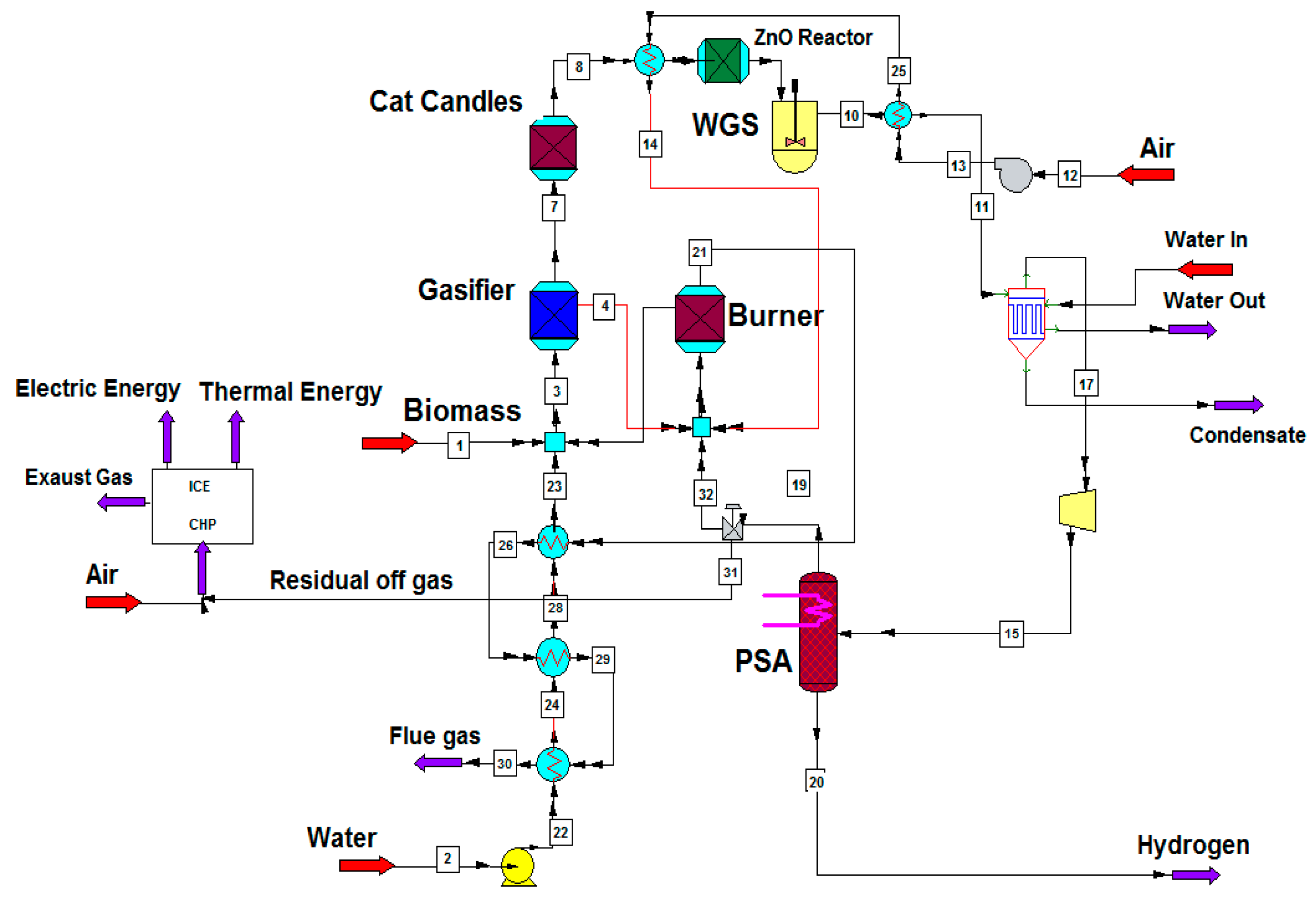
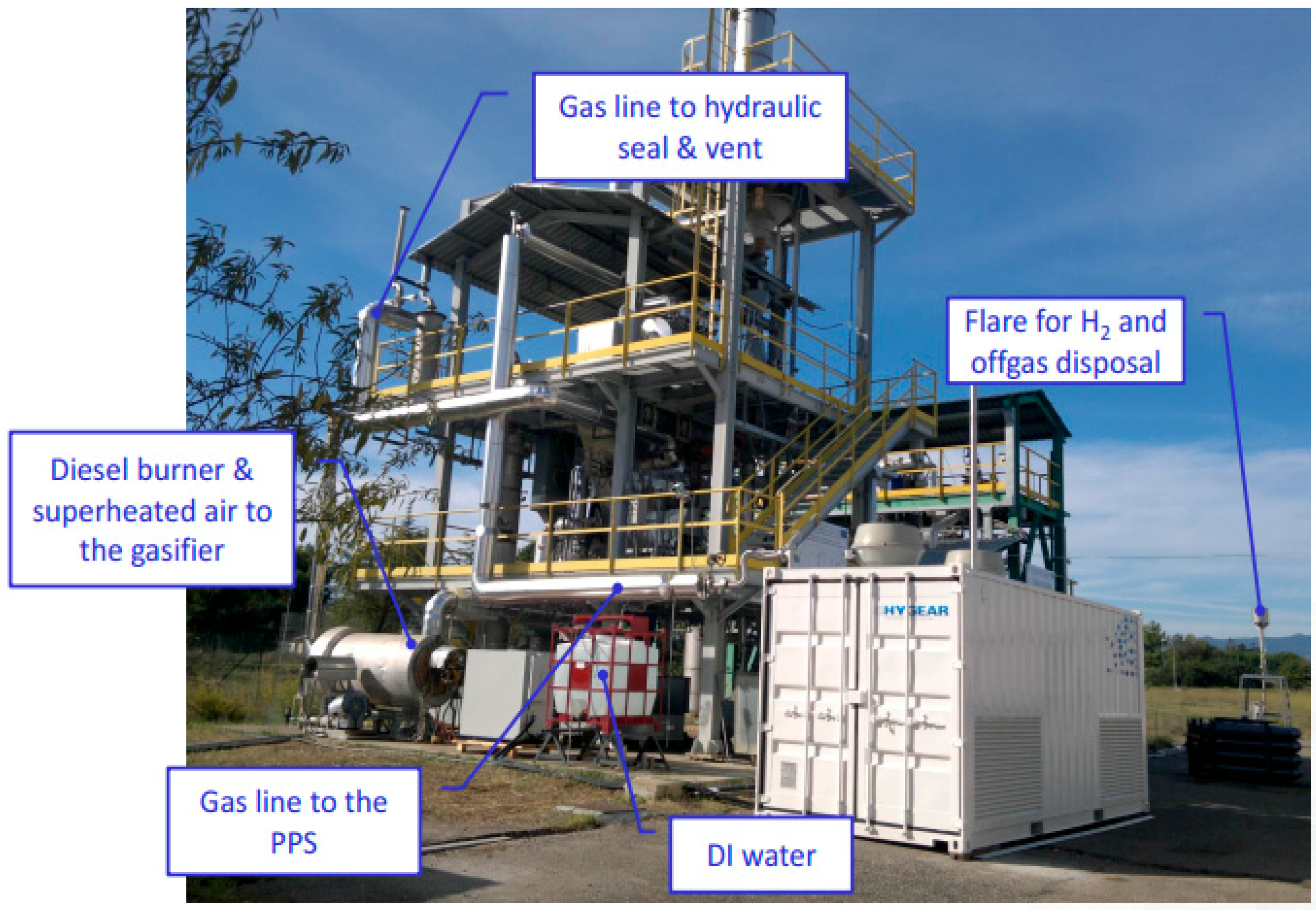
Figure 1 shows the CHEMCAD, a simulation software for chemical process, flowsheet of the system with the indirectly heated gasifier here considered. To realize the 1 MW
th system with Steam–Oxygen gasifier, the depicted plant in
Figure 2 is used.
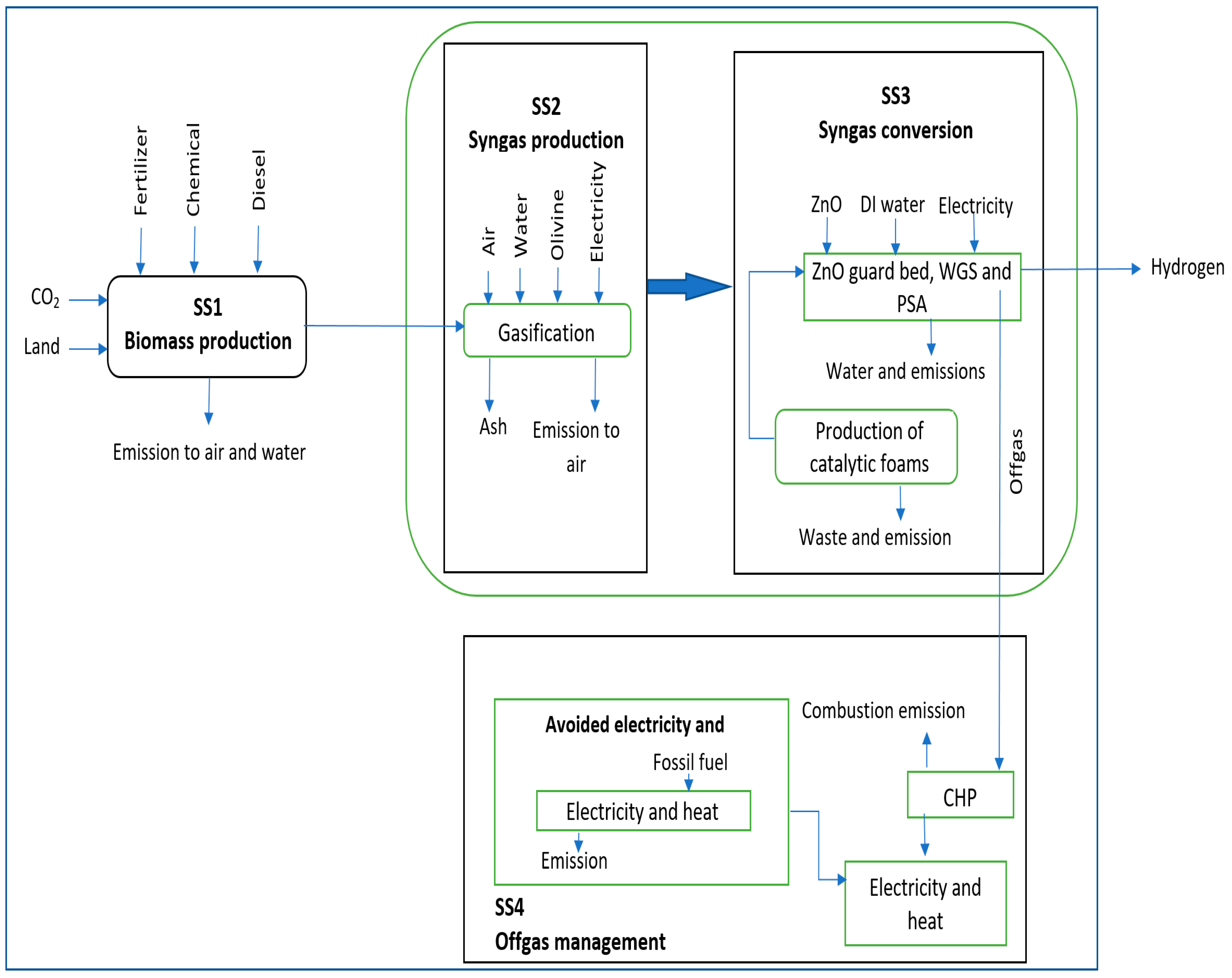
The system is divided into four subsystems. First is the Biomass production (SS1). The bioenergy plant operation has been divided into two main stages: from biomass to syngas representing the syngas production stage (SS2) and from syngas to hydrogen representing the syngas conversion stage (SS3). All inputs and outputs demanded for the plant operations are included to consider the related environmental burdens. The last subsystem is composed of the off-gas management (SS4).
Figure 3 illustrates the system boundaries and the considered processes.
3.1. Subsystem 1: Biomass Production
In Subsystem 1, all the biomass production processes were considered, comprising main crop planting, fuels consumed by agricultural machinery, requirements of fertilizer, pesticides and water for irrigation, transportation, fuel consumed in factory and biomass collection [
29,
44,
45]. The global inventory data for this subsystem are reported in
Table 1. Since waste production is not the goal of farming, it is required to designate all outputs (main products and waste) of cultivation and adapt allocation method to account only for the environmental burdens allocated to waste [
21,
27]. In this study, environmental charges of cultivation stage are allocated using market prices (1% of charge associated to waste).
3.2. Subsystem 2: Syngas Production
The main operating conditions of the entire power plant are listed in
Table 2 [
38]. In addition, almond shell characterization and syngas composition are shown in
Table 3 and
Table 4, respectively.
Syngas production stage involves the gasification process. Gasification is performed in a 1 MW
th Indirectly heated Bubbling Fluidized Bed gasifier (IBFB), working under mentioned conditions in
Table 2 for 7000 operating hours (even if during the project only 120 h of pure hydrogen production has been achieved). Indirectly heated bubbling fluidized bed with tar reforming inside the gasifier was chosen in this study since this configuration provides a synthesis gas with higher hydrogen content than fluidized and fixed bed gasifiers [
6,
36,
41,
47,
48,
49]. The 1 MW
th gasifier built and experimented in the research project is an oxygen bubbling fluidized bed gasifier. Thus, we considered the same technology running in indirectly heated configuration.
First, tar and methane are treated and the cleaning process of synthesis gas from particles is carried out by 60 Catalytic Filter Candles (CFC) allocated in the gasifier freeboard. This is an innovative method adapted and tested during the two European research projects called UNIQUE [
50] and UNIfHY [
25]. In the gasification process, both electricity and heat are requisite. The electricity consumed in the syngas compressor and in the air blower is taken directly from the Italian national grid. Thermal energy is required to preheat the air, heat the water, and generate and overheat the steam, and is provided by syngas and flue gas cooling. Owing to the indirectly heated configuration, hot bed material (olivine) from the combustor is circulated back to the gasifier supplying the thermal power needed for the gasification reactions. Carbon dioxide emissions from flue gas have been considered.
3.3. Subsystem 3: Syngas Conversion
In the syngas conversion stage, the produced syngas has been used in a portable purification station (PPS), which generates the H
2. This unit combines a ZnO reactor (to remove the sulfur compounds within syngas), a WGS reactor (to convert CO into further H
2) and a PSA membrane reactor (to separate H
2 from the other syngas components). Since atmospheric pressure gasification is more suitable for small-scale applications, the conventional WGS that operates at high pressure has been substitute with ceramic foams catalytic WGS operating at atmospheric pressure. The use of a ceramic foam with a wide catalytic surface area impregnated with catalyst eliminates the need to operate at high pressure for high conversion efficiency [
36].
The ZnO data have been considered but this unit is not present in the flowsheet because the trace elements have not been considered in the simulation. The heat from the heat exchangers in PPS is recovered to meet low temperature thermal need.
All inputs and outputs needed for the hydrogen production unit (PPS), such as electricity, ZnO, de-ionized water and WGS Cu foams, are included. Additionally, the derived emissions from burning off-gas (such as nitrogen oxides, carbon dioxide, and sulfur dioxide) were considered. Construction of gasifier plant with 20-year life time has also been considered within the subsystem boundaries. The details of catalysts production are extracted from a questionnaire filled out by the University of Strasburg, a partner of UNIfHY project. The materials and energy inputs required for the catalysts production to be used in a 1 MW
th power plant are presented in
Table 5.
During the 20-year lifetime of power plant, the catalysts with three-year lifetime need to be replaced seven times. To integrate this production phase into the model, the energy and materials required for these catalysts (
Table 5) have been multiplied by seven and divided by the total energy output produced during 20 years.
The main inventory data for hydrogen production via almond shell gasification are shown in
Table 6.
3.4. Subsystem 4: Off-Gas Management
In the syngas conversion process, off-gas is co-produced from PSA and is mainly used in the burner (syngas production process). This subsystem involves the use of the residual off gas into a conventional Combined Heat and Power system (CHP, via an Internal Combustion Engine, ICE). Under the conditions mentioned in
Table 2, with respect to the total energy output: the energy content of residual off-gas represents 12%; the H
2 represents 43%; and the thermal energy losses are 45% (8% in flue gas and another 37% mainly due to the heat of the cooling water and condensate) (
Figure 1).
According to previous energy study of the authors [
38] and Fremaux et al. [
37], it is inferred that the residual off-gas decreases with higher S/B ratio (e.g., with S/B greater than 1.5–2, depending on the PSA efficiency, the off-gas is completely used in the burner). In particular, the global efficiency is limited by the thermal losses and by the PSA compressor consumption. The hydrogen efficiency is limited by the PSA efficiency and by the absence of a methane reformer. Thus, to increase the hydrogen efficiency, high temperature hydrogen membrane separation that works at low pressure (as Palladium membranes) including methane reforming are considered but, up to now, are still in a development phase. Indeed, the hydrogen efficiency is about 38%, while the global efficiency (considering hydrogen, residual off gas and the useful heat) is about 70%.
The production of off-gas, under the fixed gasification and conditioning parameters (residence time, temperature, catalysts, etc.) mainly depends on S/B ratio and PSA efficiency. Being the PSA efficiency a technological parameter rather than an operational parameter, only the variation of S/B has been considered in the following sensitivity analysis.
The off-gas use for CHP was considered within the system boundaries together with the consequently avoided conventional electricity production, while heat generation has been disregarded. Indeed, electricity can be used for own demand and injected to the grid, meanwhile the heat produced by CHP can only be used if there is a near low temperature heat demand. In accordance to ISO standards, allocation procedure is avoided by system expansion in this LCA study.
During biomass-based hydrogen production, hydrogen and off-gas are coproduced. The hydrogen was considered as the main product, although the produced electricity from off-gas can be sold to the national grid. In fact, it is considered as an avoided input in the base case of this study. In other words, the system is expanded rather than allocated. Therefore, hydrogen production was only addressed as the base case. In addition, impacts derived from the production and transmission of the avoided electricity were also included within the subsystem boundaries in this case.
4. Results
Table 7 summarizes the LCA characterization results for the different subsystems under study per functional unit. Positive values are environmental burdens while negative values signify environmental credits or benefits accrued from carbon dioxide uptake and the substitution of electricity from national grid.
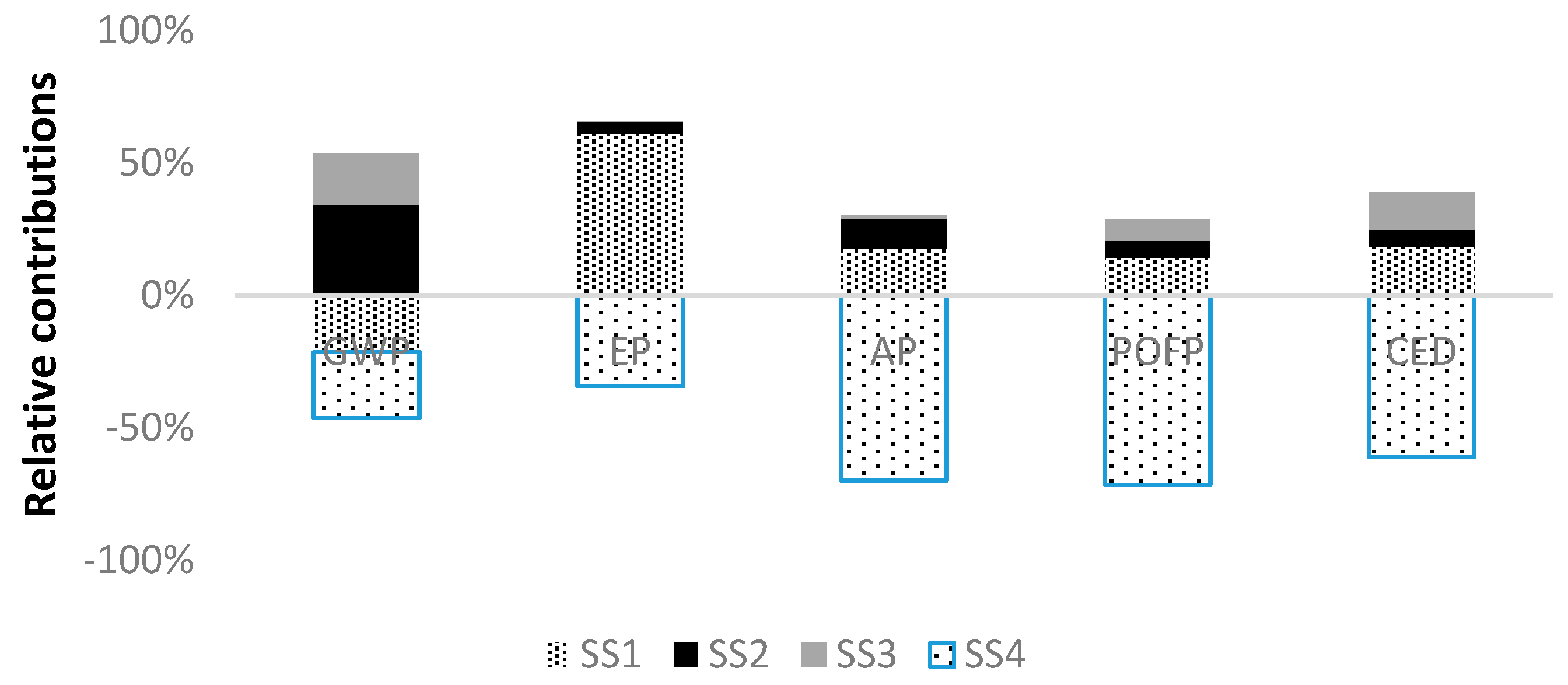
Figure 4 displays the relative contributions of each subsystem to the environmental results for the studied system. According to these results, the biomass production (SS1) shows high influence over the environmental profile, especially in term of EP with a contribution of 60%. This result is mainly related to the emissions derived from fertilizer application. In addition, the large amount of energy required to produce fertilizer causes intense fossil energy consumption in feedstock production phase. Contrarily, this subsystem achieves a positive effect on GWP owing to the CO
2 uptake by photosynthesis. Therefore, the emission of 120 g CO
2 eq per functional unit is avoided. The main environmental impacts of the syngas production (SS2) are observed on GWP (34%) and AP (15%), mostly related with flue gas emitted from gasifier combustor and feedstock supply. The syngas conversion (SS3) has relatively lower impact on GWP (19%) than the other categories.
SS4 covers the energy generation from off-gas and its utilization as electricity. Thus, the production of electricity from the grid is avoided. As shown in
Table 7, it leads to environmental benefits in terms of all the analyzed categories. In the following, a detailed assessment per subsystem has been carried out to recognize in detail the main contribution to these environmental outcomes.
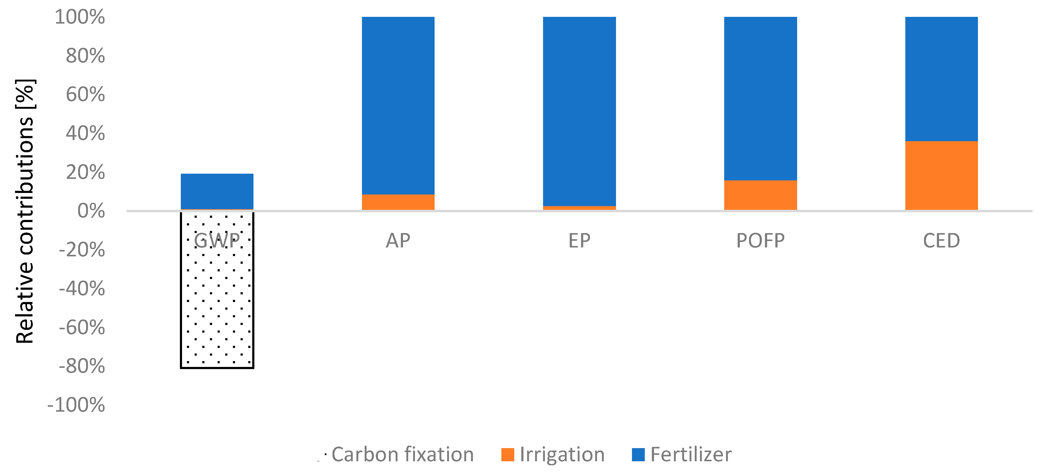
As displayed in
Figure 5, impact of fertilizers in SS1 is notable in EP, AP and POCP categories with a contribution greater than 84% because of drastic energy consumption in production of nitrogen fertilizer required. Irrigating orchard, owing to diesel and electricity requirements in irrigation, has also impact on AP and POFP with 5% and 15%, respectively. Regarding GWP, the fixation CO
2 by photosynthesis can offset the GHG emitted throughout the cultivation system which are chiefly derived from fertilizer production.
With regard to the syngas production process (SS2), flue gas emission from gasifier burner has the largest proportion of total GWP (55%). By virtue of carbon fixation of feedstock, this impact eventually experiences a massive decrease.
The other categories (AP, POFP and EP) are significantly influenced by feedstock supply process. Moreover, the electricity required to run the gasification has been taken from the Italian grid; its production turns out as second large contributor for AP and POFP categories with 16% and 23%, respectively. Eighty percent of the electricity consumption in SS2 is due to the air blower to provide air needed for gasification process.
In SS3, the syngas production phase impacts on all the environmental categories. In particular, for EP, it impacts with 97% related to feedstock and fertilizer consumption. The materials used for syngas conversion to hydrogen have minor impact on this subsystem. Among them, the Cu foam production has higher environmental impact than the other materials accounting for almost the 3.6% of the impact on AP and POFP.
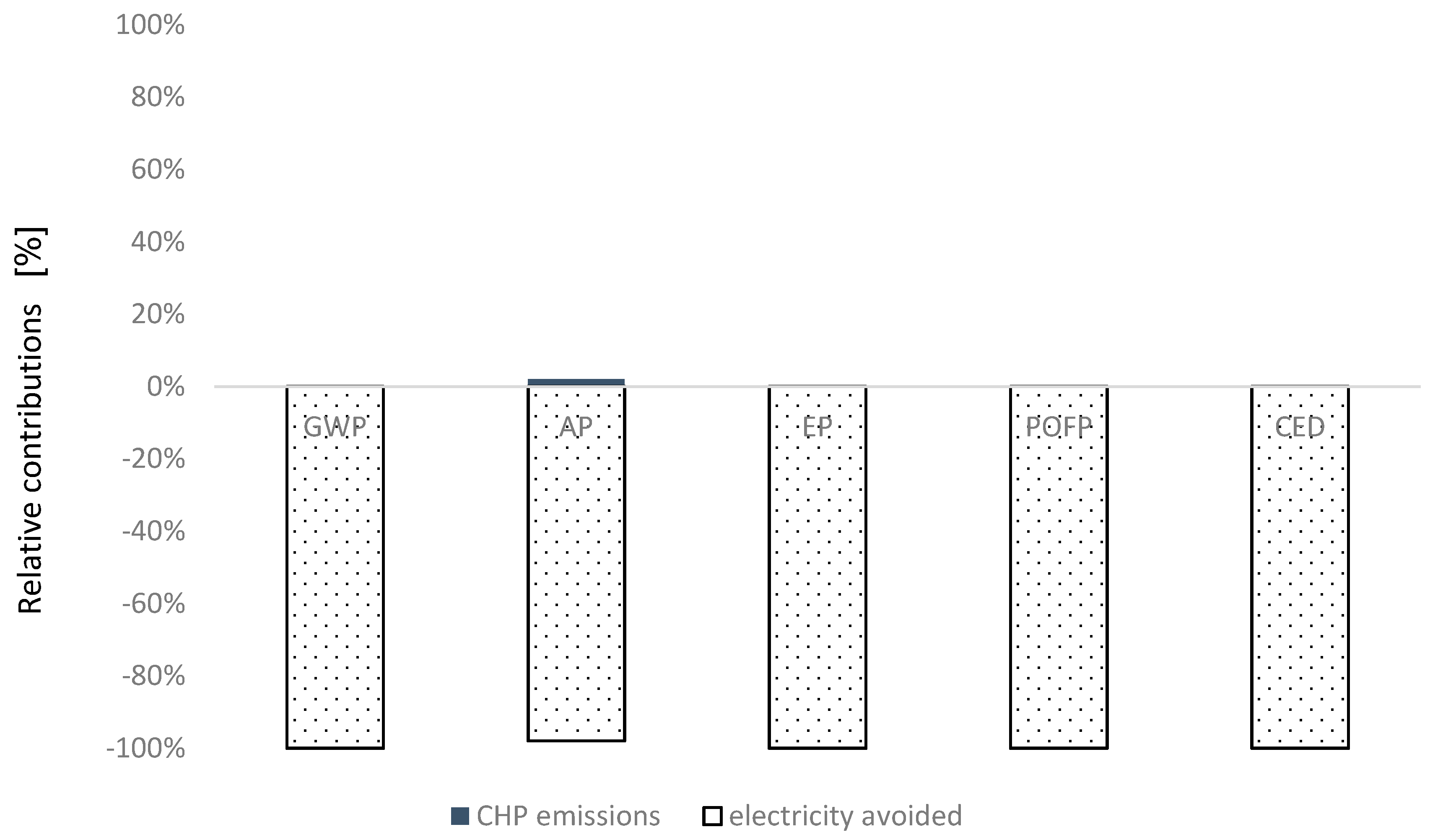
In SS4, the emissions from the CHP (SO
2 and NO
x) have been estimated according to emission limits legislated by European Commission. Carbon dioxide released by off-gas burning is biogenic and it is not treated as a net source of carbon dioxide by IPCC. The detailed information is indicated in
Table 8. The avoided emissions from electricity production and transmission, as shown in
Figure 6, have the greatest negative impact on all categories.
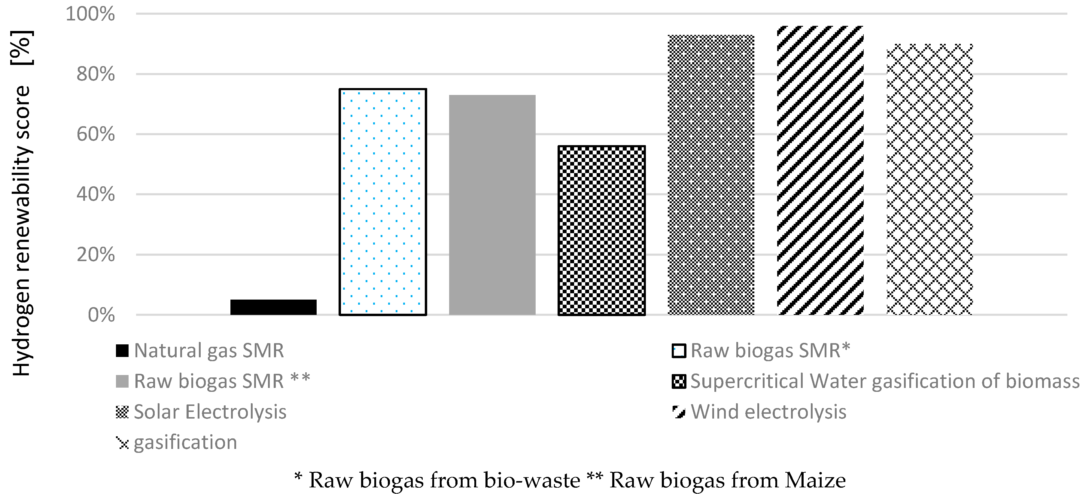
The renewability score of hydrogen under the conditions considered in our study has been fixed at 90%, which is close to the values defined for wind and solar based hydrogen production, 96% and 93%, respectively [
51]. In fact, high energy saving in SS4 leads to achieving this appreciative value.
To calculate the renewability score in the current study, the energy content of biomass as the renewable energy was considered 18 MJ/kg
biomass [
46]. Therefore, the consumption of 0.144 kg biomass per 1 MJ
H2 equals to 2.6 MJ biomass-renewable energy consumption. According to the cumulative energy demand indicator (
Table 7), 0.46 MJ energy per 1 MJ
H2 would be saved in the whole life cycle. In fact, the electricity produced from off-gas leads to 1.3 MJ energy saving per 1 MJ
H2. The non-renewable energy of whole life cycle has been calculated as 0.22 MJ/MJ
H2 considering 43% contribution of off-gas treatment subsystem (SS4) to save energy. On the other hand, if SS4 were excluded from the model, the H
2 renewability could be expressed as 75%. In other words, off gas treatment can improve hydrogen renewability by 15%. According to [
6] and
Table A1 in
Appendix A, other approaches for hydrogen production are compared in
Figure 7.
5. Discussion
In this section, the results obtained in our study for the GWP, AP and EP impact categories are compared with other LCA studies. To simplify these comparisons, our results are presented using the same functional units as other studies (0.042 kg CO2 eq per MJH2, 0.45 kg CO2 eq per Nm3H2 or 15.96 CO2 eq g/s).
Kalinci et al. [
9] reported values of GWP as 17.13 CO
2 eq g/s in the CFBG system and 0.175 CO
2 eq g/s in the DG system. In this study, the production of pine wood as feedstock for H
2 production in Proton Exchange Membrane (PEM) fuel cell vehicle were defined into system boundary. H
2 compression and transportation have been found as the main sources of environmental impact. Although the authors consider more subsystems and a wider system boundary, their result for the CFBG (comparable with our system) is just marginally higher than the one of our system. This is justified by the kind of biomass used, which does not need cultivation process and has a greater carbon fixation.
Moreno and Dufour [
21] reported values for the GWP concerning different biomasses. Economic allocation has been considered to designate relevant emissions to waste biomass in orchard products. They found that use of allocation approach leads to decrease in CO
2 fixation and carbon credits of waste, since it is distributed between fruit with 90–99% of total price and waste. Therefore, the GWP, for almond pruning, by considering or not the allocation has been determined as 1.5 and 0.18 kg CO
2 eq per Nm
3 of hydrogen, respectively and GWP for vine pruning by considering or not the allocation 1.1 and 0.2 kg CO
2 eq per Nm
3 of hydrogen, respectively. In this estimation, non-converted CH
4 has been recovered into system to provide energy needs. The emissions estimated in this study are slightly lower than the ones in our study due to the use different type of gasifier. In fact, in line with results obtained by [
9], fixed bed gasifier released lower emission than fluidized bed gasifier.
Thus, differences on the feedstock and the system boundaries have influence on the results and explain the variations in relation with other studies.
In other research [
52], the CO
2 emitted from raw biogas reforming under two different feedstocks (maize and bio waste) was assessed. The GWP value is estimated to be 0.046 kg CO
2 eq. per 1 MJ
h2 for maize-based biogas and 0.037 kg CO
2 eq. if bio waste is used as feedstock. The emissions from fertilizer supply and use of diesel for farming machines in maize cultivation are mainly responsible for these values. These results are quite similar to the system investigated in this study. However, the value reported to generate H
2 by natural gas SMR was 0.1 kg CO
2 per 1 MJ
H2 [
6,
53,
54]. Therefore, 0.058 kg CO
2 per 1 MJ
H2 can be reduced if waste biomass gasification is utilized to produce hydrogen.
Regarding the other impact categories, remarkable differences have been identified. In terms of AP and EP, Moreno and Dufour [
21] reported 0.006 kg SO
2 eq and 0.008 kg SO
2 eq and 0.03 kg PO
4 and 0.045 kg PO
4 eq per Nm
3 of hydrogen for vine and almond pruning, respectively. According to these authors, these categories were significantly affected by the emissions of nitrate and ammonia used as fertilizer.
Thus,
Table 9 summarizes the differences with the reviewed studies.
Sensitivity Analysis
Sensitivity analysis has been performed to assess influence of H
2 productivity and the allocation method used in the model. As mentioned in
Section 2, among several factors affecting H
2 productivity, the steam to biomass ratio (S/B), (see
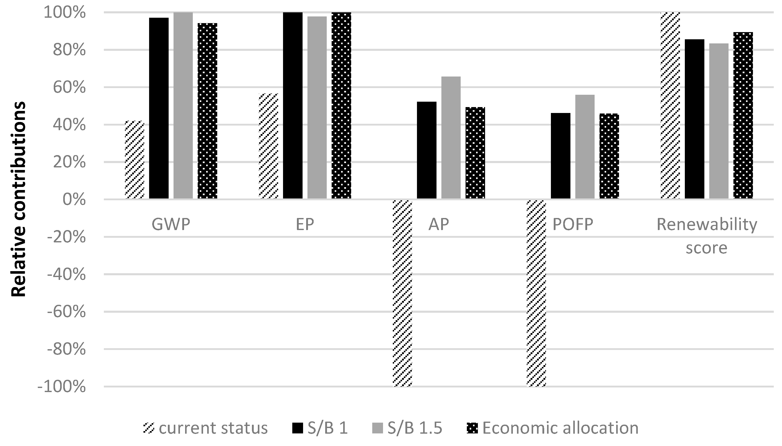
Section 3.4) has been chosen to assess hydrogen production. In
Figure 8, the current status characterizes the gasification system presented in
Section 3 (S/B = 0.5). This status has been compared with the LCA output considering the S/B ratio equal to 1 and 1.5 (
Table 10). Therefore, the results of this study have been compared with results related to S/B 1 and 1.5. The experimental conditions for these different ratios are found in [
38].
According to
Table 10, increasing the steam to biomass ration improves gas yield and H
2 production but also the CO
2 and H
2O content. The gas yield and H
2 production increase is more relevant than the increase of inert gas, because the LHV of the syngas increases [
36].
Figure 8 shows that, in cases of S/B 1 and 1.5, impacts are higher (from 60% of GWP to around 100% for AP and POFP). Numerical values related to
Figure 8 are presented in
Table 11. This is due to the decrease in electricity production and subsequently decrease in environmental benefits (see
Section 4). In addition, regarding renewability score, the case of S/B 0.5 shows the best performance. The economic allocation case, where environmental impacts are allocated to H
2 and electricity, shows environmental improvements compared with the case of S/B 1 and 1.5 but always higher than the case of S/B 0.5. This means that increase in hydrogen production not necessarily results in diminution of environmental impacts on the contrary these impacts can grow. Rise in hydrogen produced leads to fall in off-gas volume, electricity obtained and its avoided impacts. These results clarify role importance of by-products in environmental efficiency of hydrogen production. In addition, as the Italian electric profile includes high fraction of non-renewable sources in [
27], which results that more than 65% is generated from non-renewable sources, mainly natural gas, oil and hard coal, renewability of hydrogen can be affected by decline in avoided grid derived electricity demand, which entails consumption of fossil-based electricity due to drop in off-gas volume.
Decentralized power plants entail environmental benefits despite the technical and economic challenges for this scale of power plant. Indeed, investment cost per power unit of small scale power plants is higher than large scale plants and there are higher requirements for the technological development of these small-scale power plants (thermal balance, etc.). Moreover, hydrogen production cost can be higher (10 euro/kg) compared with large scale production cost (1–2 euro/kg).
On the other hand, the energy, economic and environmental impacts of the biomass transportation are relatively lower due to avoiding distribution and because CHP and CCHP systems can also be more applicable for small scale power plants as heating and cooling production is more effortlessly distributed and usable. In fact, currently, hydrogen production systems at large scale can be more technically and economically applicable, but they impose higher impacts.
6. Conclusions
This study evaluates the environmental characteristics of hydrogen and electricity production in an innovative small-scale biomass gasification plant. The LCA methodology has been applied to assess the environmental performance of this production scenario.
Real input and output flows for the whole system have been identified and managed in detail from a cradle-to-gate perspective. This study showed that the biomass production phase influences all impact categories, which is a unanimous result of previous research. Furthermore, due to multifunctional nature of this process and considering byproduct converted into electricity as well as no auxiliary energy consumption, these environmental impacts massively decrease. Negative values in AP, POFP and CED illustrate this improvement. Following this result, a sensitivity analysis was conducted to assess the influence of the variations in hydrogen and byproduct volume on environmental impacts. The S/B ratio has been chosen as parameter affecting both off-gas and hydrogen production because it is commonly recognized as the main factor in the analysis of performance of gasification process. Results indicate that, although increase in hydrogen production can directly reduce all environmental impacts, this implies a fall in off-gas volume, which indirectly leads to increased impacts for all categories. As a result, in the considered production system, the environmental effects cannot be univocally represented by hydrogen production rate because relevance of byproducts produced plays an even more important role. In this line of research, development of system boundary into bio-refinery products can also lead to higher reduction in environmental footprints of hydrogen production system. In addition, the sensitivity analysis shows that allocation method also highly affects the system profile. Allocation of environmental charges can considerably overestimate results. Results of this work have a relevant impact with respect to previous literature works regarding hydrogen production by means of biomass gasification because it has analyzed the effect of some design parameters on the environmental impact of the overall system, quantifying the contribution, for each category, of the different configurations.
Finally, despite the limits of small scale hydrogen production system, many potential advantages of this category can be enumerated. Therefore, a highly efficient small-scale power plant with low environmental burden needs to be developed to tackle the low energy density and perishability of biomass.

 ,
, 


