Numerical Study on Heat Transfer to an Arc Absorber Designed for a Waste Heat Recovery System around a Cement Kiln


Department of Energy Technology, Aalborg University, Pontoppidanstræde 111, 9220 Aalborg East, Denmark
*
Author to whom correspondence should be addressed.
Energies 2018, 11(3), 671; https://doi.org/10.3390/en11030671
Submission received: 23 January 2018
/
Revised: 14 March 2018
/
Accepted: 14 March 2018
/
Published: 16 March 2018
(This article belongs to the Section I: Energy Fundamentals and Conversion)
Abstract
:A numerical study on combined free convection, forced convection, and radiation heat transfers from an industrial isothermal rotating cylinder (cement kiln) is carried out in this work. The investigation is done by the study of two-dimensional (2D) incompressible turbulent flow around the kiln under steady- and unsteady-state solutions. The results of this study show that the average Reynolds and Rayleigh numbers around the cylindrical kiln are 647,812.1 and 1.75986 × 10¹¹, respectively. A heat absorber is specifically designed around the kiln, according to the available space around the kiln, in a sample cement factory. The study investigates the effect of an added absorber on the heat transfer features, for both constant heat flux and constant temperature, on the kiln. The temperature distribution along the absorber circumference is obtained for designing an efficient thermoelectric waste heat recovery system as a future study. It is observed that the contribution of the radiative heat transfer is significant in the total heat transferred from the kiln to the absorber.
1. Introduction
Heat transfer and fluid flow over circular cylinders have been studied in widespread applications, such as industrial boilers, heat recovery systems, advanced types of power plants for nuclear rockets, and so forth. In some of these technologies, both convective and radiative heat transfer should be taken into account for better prediction of the fluid flow and heat transfer. Studying the flow over a single circular cylinder gives better insight into the flow characteristics and heat transfer features that can be implemented for various heat transfer applications. Zdravkovich [1] and Williamson [2] have presented reviews on this topic in detail.
A study by Schmidt and Wenner [3] was one of the first works that reported heat transfer from a circular cylinder. Since then, many experimental results and empirical correlations have been presented in the literature for the heat transfer and hydrodynamic characteristics of circular cylinders. Sarma and Sukhatme [4] studied the heat transfer from cross-flow over a circular cylinder, experimentally, with a constant heat flow boundary condition for different Reynolds numbers (Re) in the range of 500–4700. Moreover, they investigated the effect of the turbulence intensity of free stream on heat transfer.
Jain and Goel [5] investigated the laminar forced convective heat transfer from a cylinder. The local Nusselt number (Nu) variations around the cylinder versus time were presented for two Re equal to 100 and 200. They found that their numerical results did not completely agree with the experimental results investigated by Eckert and Soehngen [6]. Scholten and Murray [7] reported the experimental results of unsteady heat transfer from a circular cylinder for a low turbulence range of free stream. Moreover, they studied a high turbulence range of free stream [8].
Sczepanik et al. [9] solved two-dimensional steady-state flow equations as well as unsteady Reynolds-averaged Navier–Stokes equations, by using the standard k-ω turbulence model as well as the T-limited k-ω model for various Reynolds numbers. Sak et al. [10] investigated the effect of turbulence intensity and turbulence integral length scale on convection rate from a heated cylinder while the Re was 27,700 in the cross-flow of the air. They presented results of their parametric study for relative turbulence intensity in the range of 2.9–8.3%, and the turbulence integral length scale to the cylinder diameter ratio in the range of 0.50–1.47.
Nakamura and Igarashi [11] studied the unsteady heat transfer from a circular cylinder, experimentally, for Re from 3000 to 15,000. They, furthermore, reported the variation of the Nu versus flow regimes behind a circular cylinder for Reynold numbers in the range of 70–30,000 [12]. An experimental study of heat transfer from a circular cylinder was reported by van Meel for Re from 5320 to 31,940 [13]. In his study, the time-averaged local Nu variation over the cylinder was presented over the studied range of Re.
Zhukauskas and Ziugzda [14] carried out an experimental study on convective heat transfer from a circular cylinder, and presented correlations for a wide range of Prandtl numbers (Pr) and Re. Chun and Boehm [15] reported numerical results of convective heat transfer around a circular cylinder up to Re = 3480 by a steady-state solver.
Churchill and Bernstein [16] developed a comprehensive correlation for calculating heat and mass transfer rate from a circular cylinder, based on the available experimental data for wide ranges of Pr and Re. Sanitjai and Goldstein [17] carried out the experimental study and obtained their results for Re from 2 × 10³ to 9 × 10⁴ and for Pr from 0.7 to 176. They presented separate empirical correlations of the average Nu for the laminar boundary-layer region, reattachment of the shear layer region, and also the periodic vortex flow region. For the average Nu, an empirical correlation was suggested, and compared with the earlier correlations by considering all the regimes.
Acharya and Dash [18] have investigated natural convection heat transfer from short and long, solid and hollow horizontal cylinders suspended in air as well as placed on the ground. In the other study, Acharya et al. [19] numerically analyzed the natural convection from a vertical hollow cylinder vertically suspended in air by changing the Rayleigh number (Ra) in the laminar flow regime (104 < Ra < 108). All simulations were done by changing the ratio of cylinder length to its diameter (L/D) over the range of 0.05–20. Forced convective heat transfer and hydrodynamic performance around a metal foam-wrapped tube has been investigated by Wang et al. [20], for a waste heat recovery system for internal combustion engines. A study on forced convection around a helically twisted elliptical (HTE) cylinder, inspired by a daffodil stem, was carried out by Yoon et al. [21]. In their study, the effect of different Reynolds numbers in the laminar flow regime was investigated. Elsherbiny et al. [22] numerically investigated the laminar natural convection from a horizontal isothermal square cylinder with a range of Rayleigh numbers from 103 to 106.
The studies discussed above have only considered convective heat transfer from cylinders, while the effect of radiative heat transfer was not included. Hossain et al. [23] studied the mixed convection flow of an optically dense viscous incompressible fluid along a horizontal circular cylinder, by considering the effect of radiation when the surface temperature was uniform. The effect of radiative heat transfer on the natural convection flow from an isothermal circular cylinder has been numerically investigated by Molla et al. [24], where the governing boundary-layer equations of motion were transformed into a dimensionless form and the nonlinear partial differential equations were reduced to conventional boundary-layer equations.
A numerical investigation of the combined gas radiation and forced convection from a circular cylinder was carried out by Pachpute et al. [25]. The fluid was assumed to be radiatively participating. All simulations were carried out for both laminar and turbulent flows. In order to reveal the roles of absorption and scattering in radiative heat transfer, a detailed parametric study was carried out by changing the absorption and scattering coefficients between 0 and 60 (m−1). Zainuddin et al. [26] numerically investigated the effect of radiation on the free convection around a heated horizontal cylinder with heat generation. The study determined the effects of radiation and heat generation parameters and the Pr on the pattern of the flow and heat transfer. Nevertheless, there are a few works studying convective heat transfer around a rotating circular cylinder.
Nguyen et al. [27] studied unsteady mixed convection around a rotary circular cylinder with small fluctuations in the free-stream velocity. Several cases were simulated, for Grashof numbers (Gr) up to 2 × 10⁴, Re up to 200, and over a range of revolutions from −0.5 to +0.5. Their results showed that vortex shedding is promoted by cylinder revolution, but removed by buoyancy force. Ozerdem [28] measured the convective heat transfer coefficient, experimentally, from a horizontal cylinder rotating in quiescent air. According to the experimental results, a correlation in terms of the average Nu and rotating Re was found valid for rotating Re from 2000 to 40,000.
In the present paper, primarily the effects of thermal radiation, combined convective heat transfer, and moreover, rotation of the kiln are simultaneously investigated to predict heat loss from a cement kiln. In order to understand the effect of these kinds of heat transfer and fluid flow around the circular kiln, a comprehensive numerical simulation is carried out for both unsteady and steady turbulent flows. Then, a thermal absorber is specifically designed around the kiln according to mounting restrictions in Aalborg Portland cement factory, Denmark. In this study, the effect of the absorber on the heat transfer of the kiln regarding heat flux and temperature distribution is considered by two approaches: constant temperature and constant heat flux on the kiln surface, respectively. The temperature distribution along the absorber circumference is obtained for designing an efficient thermoelectric waste heat recovery system in future.
2. Problem Statement and Computational Domain
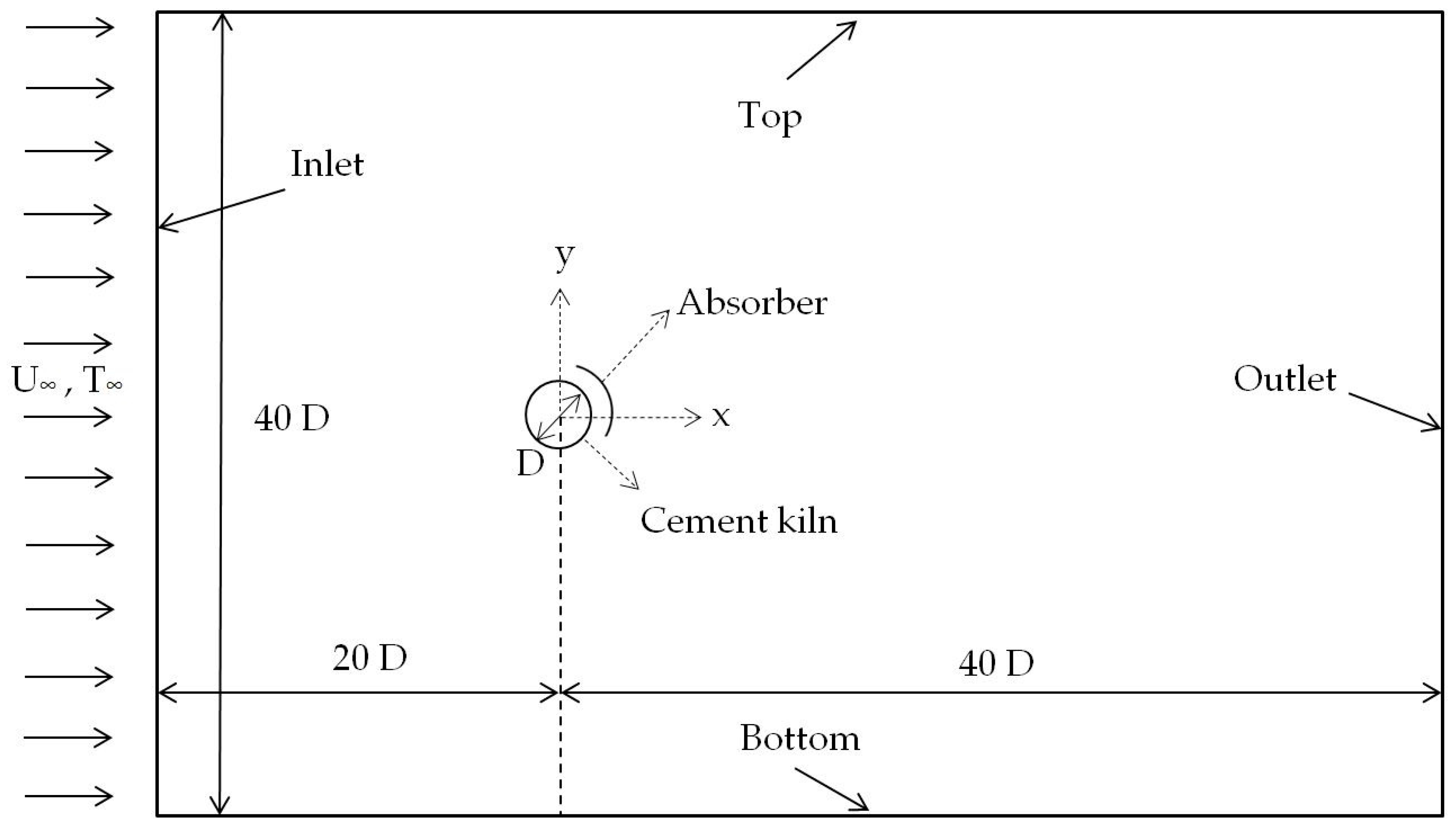
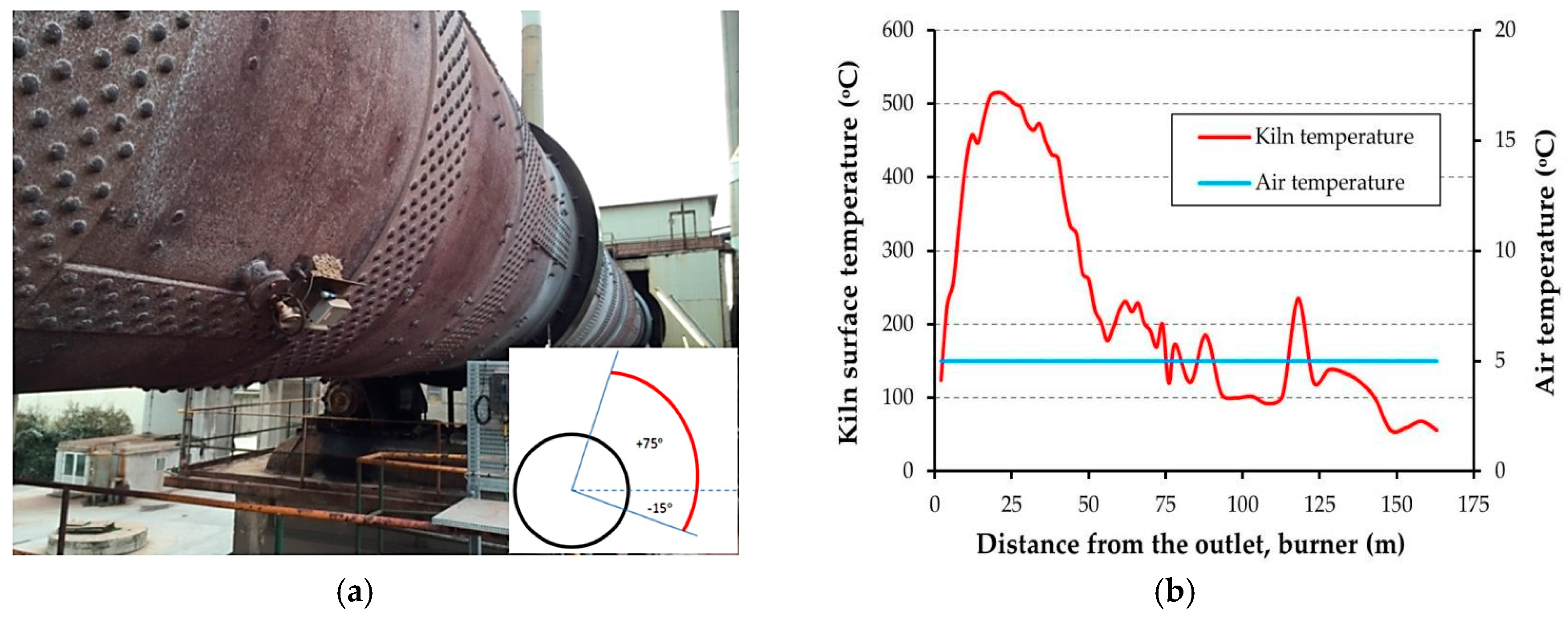
This numerical study is defined to evaluate the thermal energy absorbed by the arc absorber designed around the cement kiln for waste heat recovery applications. Beforehand, assessment of the heat loss from the rotary kiln is needed. Air is considered as the working fluid; the kiln temperature, Tkiln, is maintained at 773.15 K (500 °C); and the free-stream air temperature, T∞, is assumed to be 278.15 K (5 °C). According to the combination of different kinds of heat transfer methods at high temperatures and high Reynolds and Rayleigh numbers, the flow is intrinsically turbulent. This study has been done with a two-dimensional (2D) computational model. The computational domain considered for this numerical study is shown in Figure 1. The center of the kiln is placed at 20 D from the inlet of the computational domain. The computational domain width is 40 D, to realize the free-stream condition at the bottom and top boundaries. To prevent the effect of an outflow boundary condition on the fluid flow and heat transfer features in the wake region, the computational domain length from the center of the circular cylinder to the boundary of the outlet is taken as 40 D. The cement kiln is a circular cylinder of steel. An aluminum alloy slab, resistant to oxidation in rainy weather, is selected as the absorber. The thickness of the arc-shaped slab is 2.5 cm. The radial distance between the inner radius of the absorber and the kiln surface is 70 cm. The radiative emissivity factor of the kiln surface is considered to be 0.81, while it is taken as 1.0 for the absorber surface. Absorbing the highest possible amount of thermal energy from the waste heat is the main goal for mounting the absorber. Therefore, in order to enhance the radiative absorption capability, the aluminum surface is assumed to be refractory or painted; either way, its emissivity factor is close to that of a black body. A picture of an Aalborg Portland cement kiln is shown in Figure 2a. A schematic view of the absorber designed around the cement kiln in this study is shown in the corner of this figure. The kiln surface temperature profile along its length and ambient temperature, given by the cement factory, is represented in Figure 2b. According to the temperature distribution along the kiln length, a temperature of about 773.15 K (500 °C) is the highest temperature on the kiln surface. Therefore, the position corresponding to this temperature is the most appropriate location for heat recovery purposes.
3. Numerical Study and Mesh Independency
Governing equations for the 2D flow include the continuity, the momentum (Navier–Stokes, NS equations), and the energy equations. These equations are presented in detail by Incropera et al. [29]. Obtaining an analytical solution from the NS equations is often tedious or impossible, unless the problem is simplified. An alternative way is to approximate the governing equations with simpler algebraic equations.
Several methods can be used for this approximation, but the finite volume method (FVM) is often used in the field of fluid mechanics, and will be the method applied in this study. In order to combine the strengths of the k-ε and k-ω turbulence models, the shear-stress transport (SST) k-ω is applied. This model implements the k-ω model in the near-wall regions, while keeping the k-ε model in the free-stream regions. It must be noted that the value of y+ has to remain close to 1 in order to get accurate results. y+ is defined as follows [30]:
where τw is the shear stress at the wall and yp is the distance from the wall; μ and ρ are the dynamic viscosity and density of the working fluid near the wall, respectively.
The model is built in ANSYS Workbench 17.2 (Ansys, Canonsburg, PA, USA) [31], which consists of several software tools. A CAD model is constructed in Design Modeler (Aalborg University, Aalborg, Denmark) [32], which is used as the geometric design software. The meshing is done by ANSYS Fluent Meshing (Version 17.1, Ansys, Canonsburg, PA, USA) [33], which is an integrated tool of ANSYS Workbench. ANSYS FLUENT 17.2 (Ansys, Canonsburg, PA, USA) [34] is used to solve the governing equations of the fluid flow and heat transfer. The postprocessing is prepared in CFD-Post (Version 17.1, Ansys, Canonsburg, PA, USA) [35] and MS Excel (Microsoft Corporation, Redmond, WA, USA) [36].
The chosen solver type is pressure-based for a single phase with a no-slip condition for the walls. For velocity and pressure coupling, the SIMPLE algorithm is used. For discretizing the convective terms, a QUICK scheme is applied. A second-order precise implicit method is used for discretization of the transient terms in the governing equations. The surface-to-surface (S2S) radiation model can be applied to calculate the radiation exchange in an enclosure with gray and diffuse surfaces. The exchange of energy between two surfaces depends on view factors (configuration factors) between them. The main assumption of the S2S model is that any emission, absorption, or scattering of the media between surfaces can be neglected. Hence, only surface-to-surface radiation is considered in analysis. In comparison with the discrete transfer radiation model (DTRM) and the discrete ordinates (DO) radiation model, the S2S model is much faster per iteration for simple geometries such as that studied in this research. The Rosseland model can be used only for media with large optical thickness, e.g., higher than 3. The P-1 model does not have a good accuracy since the optical thickness is small. For instance, in combustion applications where there is optically thick media, this model works reasonably accurately [37]. Therefore, for radiation modelling in this study, the surface-to-surface method (S2S) is chosen to calculate the radiation intensity and also the divergence of radiative flux, since the optical thickness in external radiation, from the kiln surface to the ambient environment, is small. The optical atmospheric thickness at sea-level lands, such as Denmark, is less than 0.5 annually [38].
The time step used for the unsteady turbulent flow is 2 × 10⁻³ s. The residual convergence criteria for continuity is set to 10−4, x and y velocities and k-ω are set to 10−6, while the energy equation is set to 10−8.
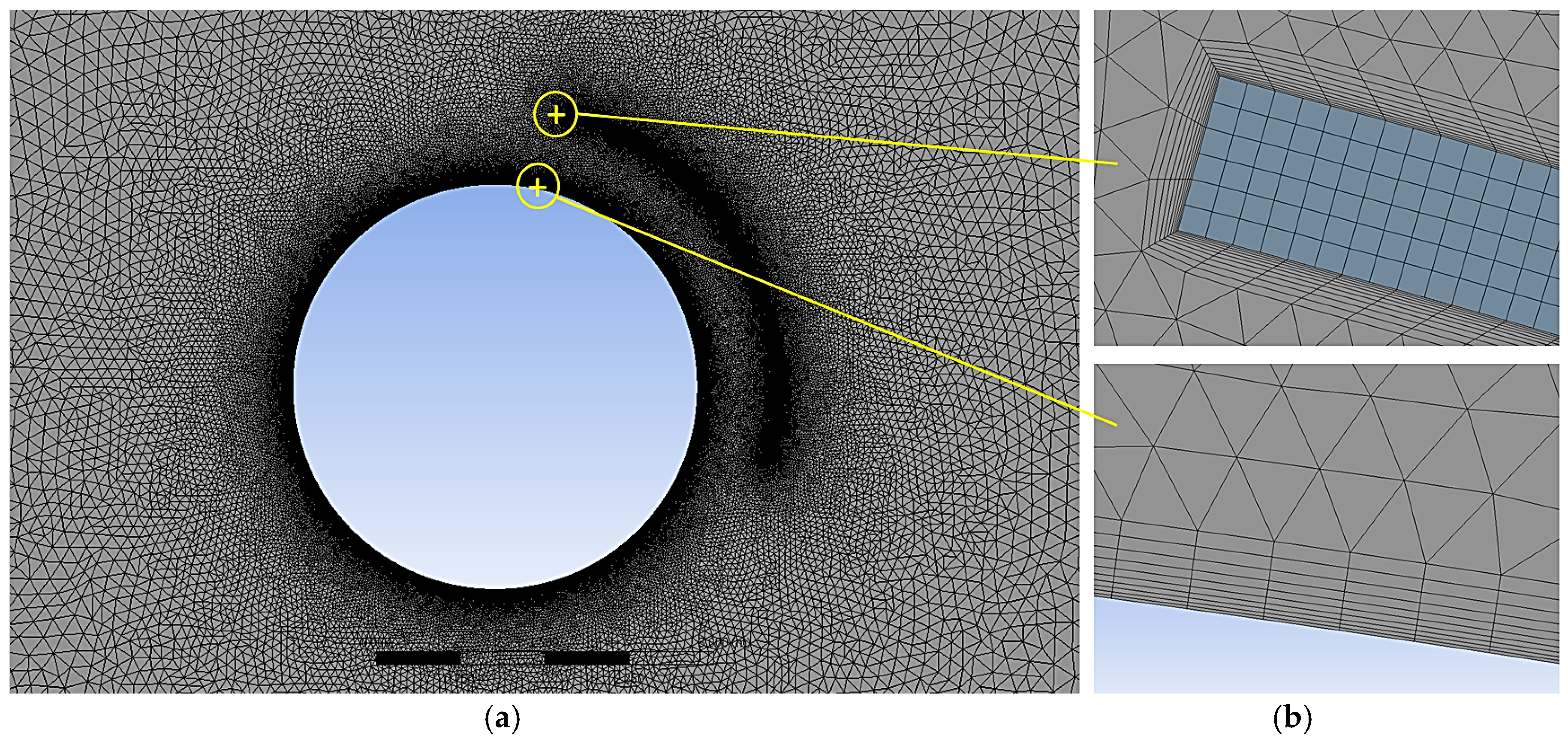
Unstructured grids are used for all the numerical simulations in this study. A typical grid used in the computational domain is observed in Figure 3a. Moreover, Figure 3b shows the detailed construction of mesh near the kiln surface and absorber walls.
To observe any changes to the results, the y+ values are checked for each grid in the domain to be about 1.0. To include thermal energy transfer, all boundaries of the rectangular domain are set to a fixed ambient temperature equal to 278.15 K (5 °C), while the circular cylinder (kiln) temperature is specified to be 773.15 K (500 °C). The diameter of the kiln is 3.6 m, which gives the Rayleigh number 1.75986 × 10¹¹. The inlet velocity is set to 5.86 m/s, which is the annual mean wind speed in Aalborg near the ground. The wind speed corresponds to a Re of 647,812.1. The kiln rotational speed is −5 rpm (≈0.5236 rad/s, clockwise). The averaged lift and drag coefficients were tracked on the cylinder surface, and when these values took the periodic oscillations, the solution was considered completed.
In order to enhance the validity of the numerical calculations, the results must be independent of the mesh. Table 1 depicts the details of the grid independency test carried out with an unsteady solution in the presence of the absorber. Based on the difference between total heat transfer rates from the cylinder obtained from the consecutive grid sizes, grid 4 is chosen.
4. Results and Discussions
4.1. Verification of the Numerical Study with Available Results
In order to verify the computational model, at first, numerical simulations are carried out for a simple problem of free convection with Ra = 100 and 105. The grid independence study is taken into consideration. The obtained Nusselt numbers are compared to those reported in the literature for the same Rayleigh numbers. All thermophysical properties of the air in the simulations are supposed at film temperature Tfilm = (Tkiln + T∞)/2.
Both laminar and turbulent flow regimes are applied for two Rayleigh numbers, to obtain the average Nu number for the comparison criterion. Because of the dispersions in the results of free convection problems, there is still uncertainty about the value of Nusselt number at a specific Ra, particularly for Ra > 103. To avoid the effect of higher Pr on the convective heat transfer, a review was published in 1997 that collected the results of 34 experimental investigations in air (Pr = 0.7) in the range of 10 < Ra < 107, and also 23 analytical and numerical studies [39]. The verification result of this work, mentioned in Table 2, is in good agreement with the Nu values of this reference.
In order to validate the results of this study, a comparison between the heat loss from the cement kiln without absorber and some empirical correlations [29] is done. In order to better the understanding of flow physics and heat transfer characteristics, a comprehensive study is done to consider both unsteady- and steady-state solutions.
By using the analytical relations, the heat transfer by free convection, forced convection, radiation, and the term of convection, as influenced by rotation, can be calculated. In Table 3, the comparison between the analytical and numerical results is shown. Empirical correlations are represented as follows.
4.1.1. Natural Convection
Equation (2) is recommended for calculating the free convective Nu in a wide range of Ra [29]:
where Ra is the Rayleigh number, Pr is the Prandtl number, Ts is the kiln temperature, T∞ is the ambient temperature, ν is the kinematic viscosity, β is the expansion coefficient, and α is the thermal diffusivity of the fluid. All properties in the above equations are taken into account at the film temperature.
4.1.2. Forced Convection
For obtaining the forced convective Nu, there is a single comprehensive equation that can cover the entire range of Re and a wide range of Pr. The equation is applicable if (Re∙Pr) > 0.2 and has the form of:
where , V is cross flow velocity, and D is the kiln diameter [29].
4.1.3. Convection for a Rotating Circular Cylinder
4.2. Numerical Analysis with the Absorber
In this section, the heat transfer and fluid flow patterns are obtained by solving the equations for the main geometry of the problem in the presence of the absorber. By referring to the results of Section 4.1 and the formation of vortex shedding around the kiln, it can be concluded that the unsteady simulation offers a better solution rather than the steady-state solution; nevertheless, the calculation time for each unsteady simulation is almost twice that of the steady-state simulation time. Therefore, the results of the unsteady solution are presented in this paper. However, a key comparison will be done between the two solutions later.
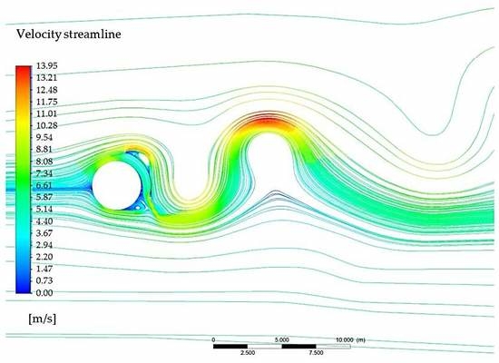
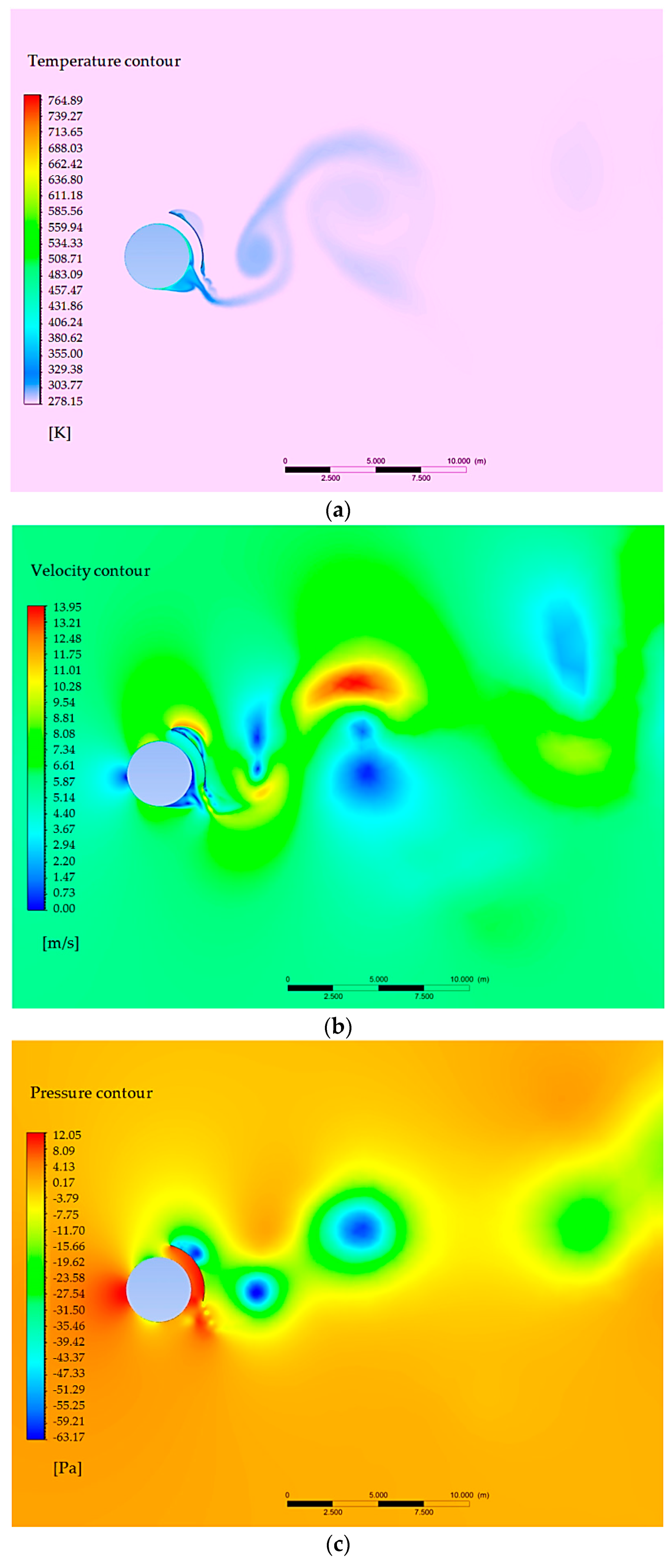
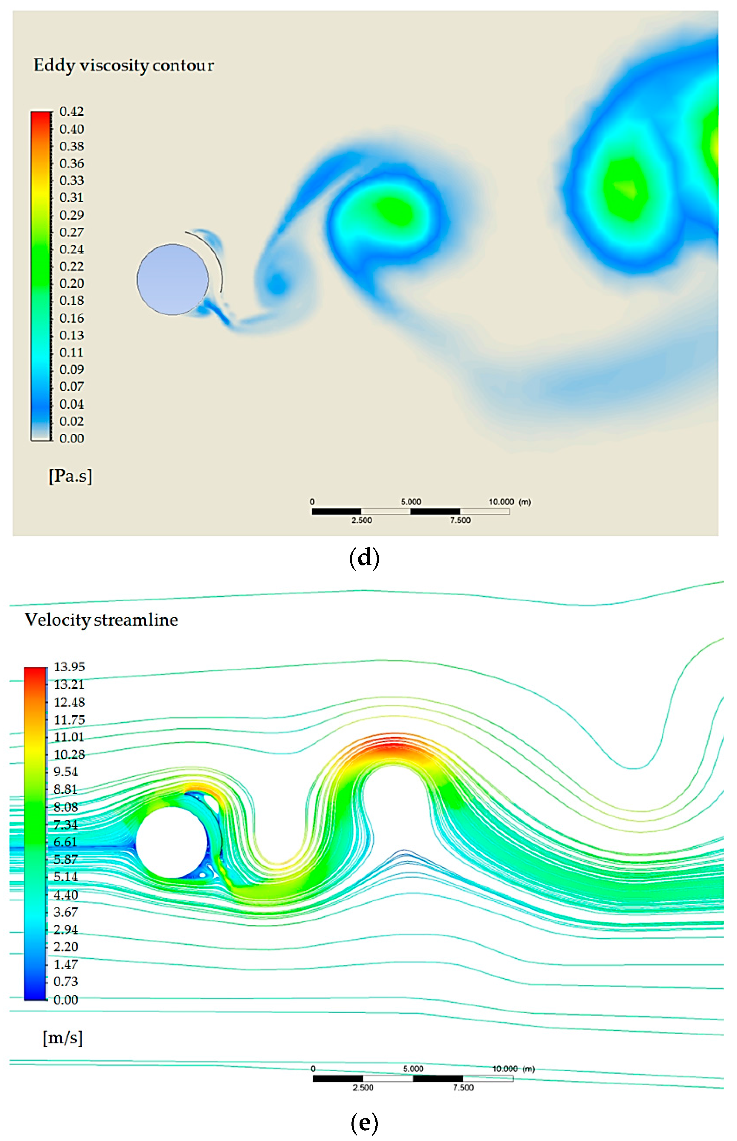
In Figure 4, the instantaneous contour of temperature, velocity, pressure, eddy viscosity, and velocity streamlines around the kiln and absorber is shown at a given time.
According to Figure 4e, the total velocity should be zero at the point where the blue velocity streamline from the upstream meets the kiln surface, although the no-slip condition has not been applied. This point is called the forward stagnation point that happens near 270° on the rotary kiln surface (see the reference angle of θ in Figure 5). The pressure at this stagnation point exceeds the pressure of the free-stream flow. The air flow velocity, which passes close to the stagnation point and has near-zero velocity, increases due to a force imposed by this excess pressure. For a kiln in the absence of the absorber, before the separation points on the top and bottom of the kiln, the velocity increases while the pressure decreases. Afterward, the velocity begins to decrease and the pressure begins to rise. Around the kiln without the absorber, this pressure increment causes an adverse pressure gradient on the boundary-layer flow. Therefore, separation of the boundary layer occurs. This cannot complete the recovery stage of the pressure, so the kiln’s rear side pressure is much lower than that in the front side. Therefore, the kiln experiences a considerable drag force.
When considering the absorber, the pressure increases in the space between the absorber and the kiln surface, whereas an intensive adverse pressure gradient occurs on the rear side of the absorber that causes an obvious flow separation in that region (Figure 4b,c,e). Since the pressure difference between the inner and outer sides of the absorber is high, a large drag force is imposed on the absorber body. Practically, this should be considered in the construction robustness of the absorber body and its holder.
The vortex shedding phenomenon affects the local features around the kiln, and in terms of time, causes periodic and transient behavior. Time-averaged values of heat loss from the kiln by convective and radiative heat transfers are depicted in Table 4. The absorber causes the radiative Nu to slightly increase, due to the enhancement of the radiative heat transfer coefficient, εσ(Ts + T∞)(Ts2 + T∞2). The T∞ represents the average ambient temperature around the kiln surface, which increases by adding the absorber. ε and σ are the radiative emissivity factor and Stefan–Boltzmann constant, respectively.
The absorber, furthermore, causes convective Nu, corresponding to cooling restriction, to reduce. In other words, the ability of air flow to cool the kiln is alleviated, where the absorber prevents the free propagation of the kiln’s heat to the surroundings. Nevertheless, the total heat loss and total Nu are reasonably decreased by implementing the absorber.
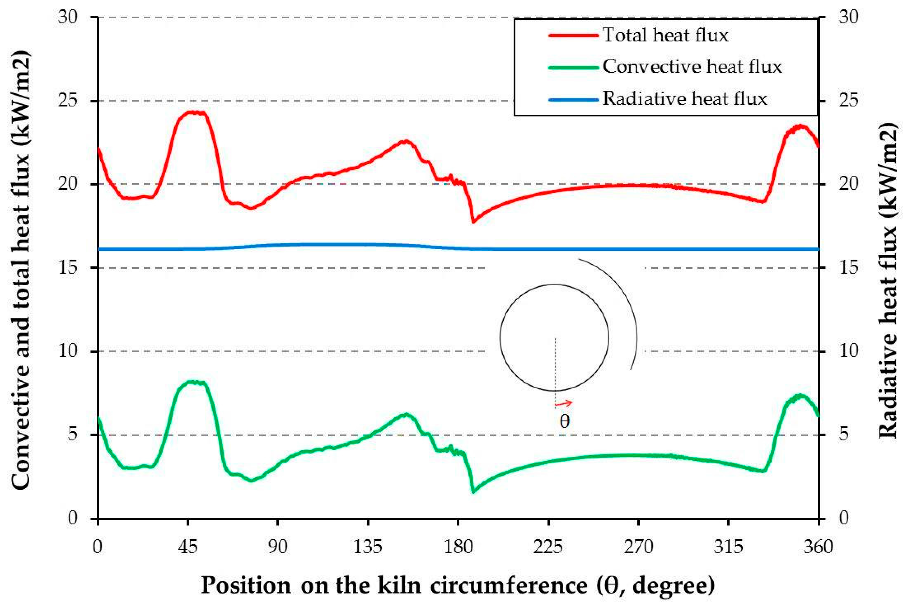
In Figure 5, time-averaged local convective, radiative, and total heat flux around the kiln can be seen. These distributions reflect various flow phenomena quantitatively. The minimum values of local convective heat flux occur at and on the top half and bottom half of the kiln, respectively, where the transition from laminar to turbulent flow in the boundary layer occurs, due to separation followed by reattachment or attached flows. The amount of convective heat flux slightly decreases from the forward stagnation point to the transition regions, where the thermal boundary-layer thickness increases. On the rear half of the kiln, the average convective heat flux increases because of the intensive motion of vortices and higher turbulence intensity. Certainly, on a portion of the kiln surface, the trend in heat flux is affected locally as a function of the absorber shape, flow vortex shedding, and direction of the wind. The local radiative heat flux is almost constant, therefore the trend of the total heat flux, equal to the summation of radiative and convective heat fluxes, has a similar trend to that of the convective heat flux.
The arc angle of the absorber is 90°; therefore, one-fourth of the radiative heat emitted from the kiln surface directly reaches the absorber. However, the air flow in the channel between the absorber and the kiln removes a fraction of the received heat from the inner surface of the absorber by convection. Convection on the inner surface plays a role of cooling fluid, and causes overall absorbed heat flux by the inner surface to decrease. The rest of this radiation is transferred by heat conduction through the absorber body. Due to the relatively small thickness of the absorber, the conductive heat transfer along the absorber body can be neglected. Therefore, the heat conduction can be considered in the radial direction to the outer surface of the absorber. Due to the small thickness of the absorber slab compared to the absorber circumference, the temperature distribution along the outer and inner surface of the absorber is found to be almost the same.
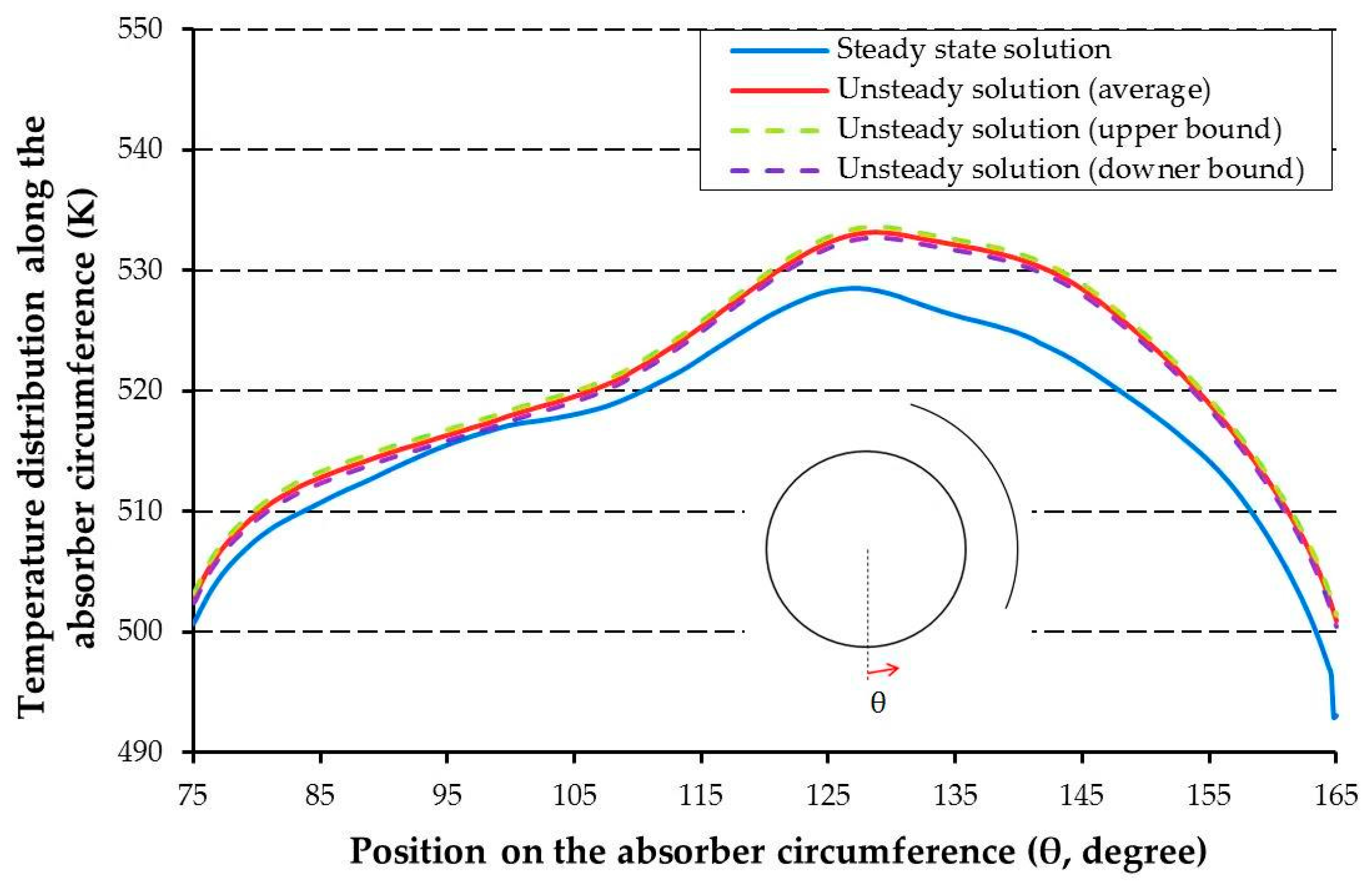
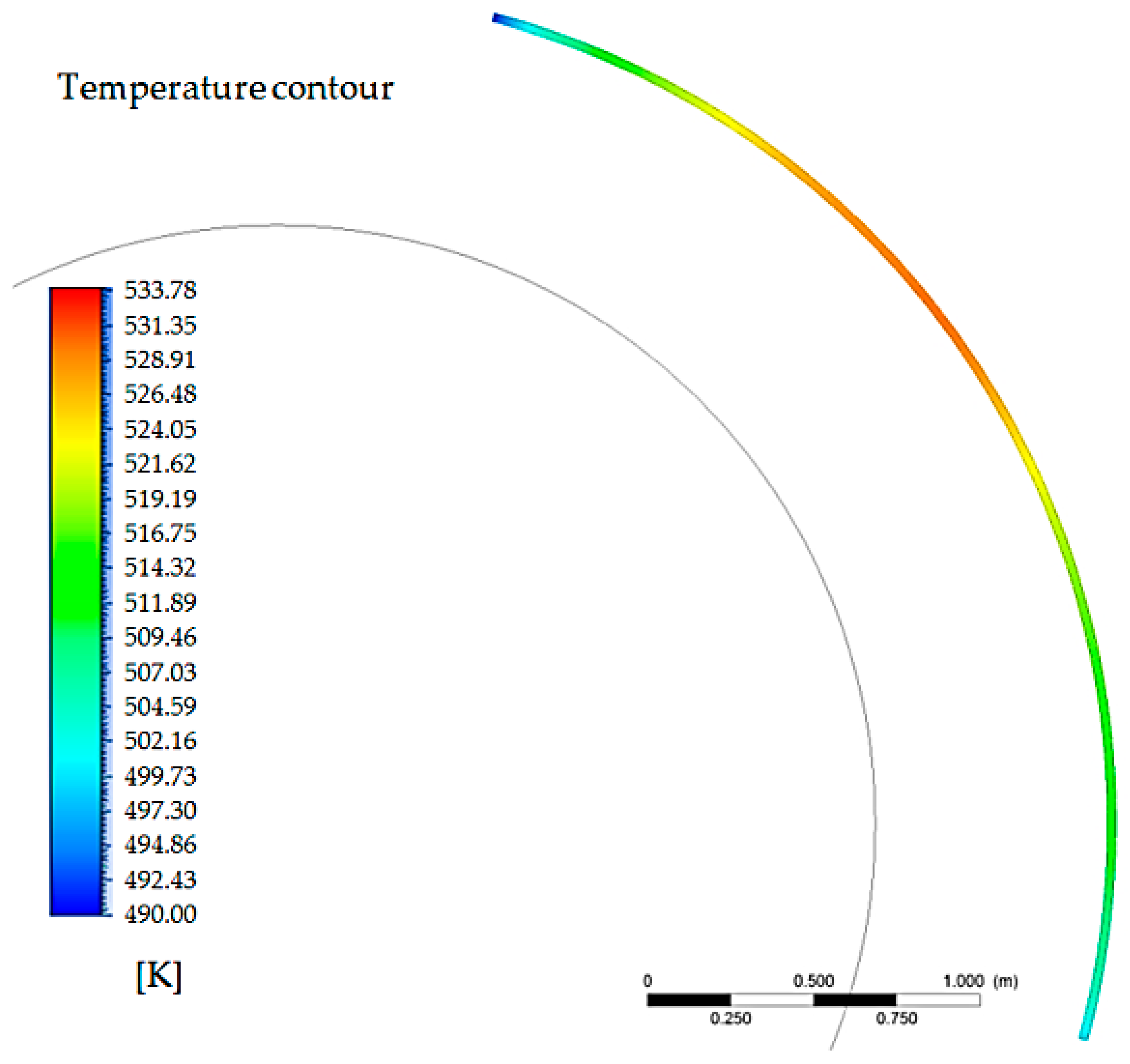
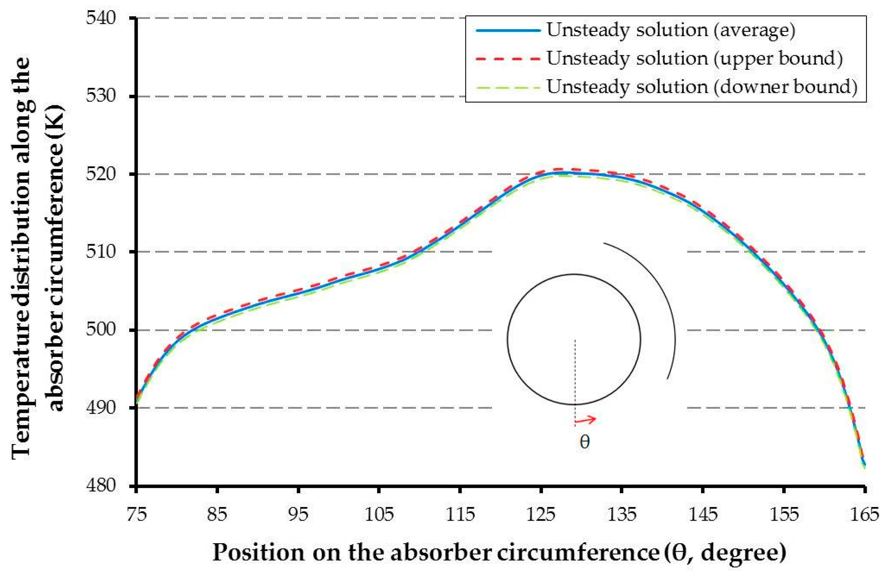
The time-averaged temperature distribution along the circumference of the absorber is shown in Figure 6. As can be seen, the periodic wake flow does not strongly affect heat transfer estimation at different times after the converging of solution, and its effect is reasonably negligible on the temperature distribution along the absorber. The downer bound and upper-bound curves around the unsteady simulated temperature distribution have been drawn by calculating the temperature standard deviation at each position on the absorber surface. It is worthwhile to point out that the difference between the unsteady- and steady-state solution results is less than 1%, as Figure 6 shows. Moreover, Figure 7 shows a cross-sectional contour of the temperature of the absorber body that graphically represents the temperature distribution of Figure 6, which was obtained by unsteady simulation. The difference between the minimum and maximum temperatures along the absorber circumference is about 32 K.
5. Supporting Study
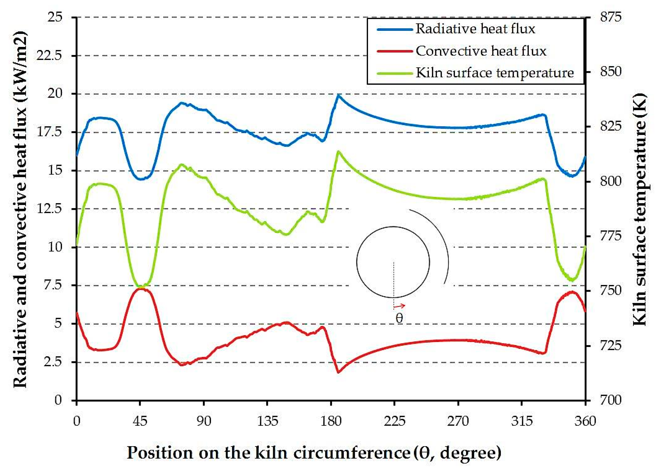
In this section, the effect of assuming a constant heat flux, instead of a constant temperature, on the kiln is investigated. It can be worthwhile to estimate the temperature distributions on the kiln and absorber circumferences when a constant energy is dissipated by the cement kiln. In this section, a total heat flux, namely about 21,739 W/m2 (as calculated from Table 3), is imposed to the kiln surface under an unsteady solution. The importance of this evaluation is to reveal critical points (hotspots) on the kiln surface which can cause cracks or damage on the kiln wall, since the production quality may be influenced by the local distribution of the kiln temperature. Although this study mainly focuses on heat transfer and fluid flow characteristics around a cement kiln, the results can be useful for industries that recover waste heat using an absorber shell. In Table 5, time-averaged heat transfer features on the kiln surface are shown. In Figure 8, the local radiative heat flux, convective heat flux, and local temperature on the kiln surface are shown. The convective heat flux distribution is almost the same on the front half of the kiln, as shown in Figure 5 and Figure 8, however, for high Reynolds numbers (as considered in this study), it is higher for the isothermal condition than that for the isoflux condition in the rear half of the cylinder [40].
In this case, the radiative heat flux distribution is different. An overall heat flux equivalent to the dissipated heat flux that caused the constant temperature mentioned in Table 3 results in temperatures higher than 773.15 K at most places on the kiln surface.
As mentioned, in the absence of the absorber, the kiln with a constant temperature can freely transfer thermal energy to its surroundings. By adding the absorber, and due to the increase of the air temperature between the kiln and the absorber, heat transfer is generally carried out to the higher temperature region. Therefore, the absorber locally amplifies the thermal resistance around the kiln, and the amount of heat loss decreases. On the other hand, the constant heat flux on the kiln surface results in an increase of the kiln’s surface temperature, to compensate the increase of the air temperature around the kiln due to adding the thermal absorber. Increasing the kiln temperature directly causes an enhancement in radiative heat flux. As can be seen in Figure 8, kiln temperature and radiative heat flux have the same trend, while convective heat flux has an inverse trend. It shows that reduction of the local convective heat transfer leads to increase the local kiln temperature.
The time-averaged temperature distribution along the absorber circumference, with the lower- and upper-bound temperature distributions drawn by using standard deviations, is shown in Figure 9. The distribution shows that the constant heat flux on the kiln can result in lower temperatures along the absorber, in comparison with the results of the equivalent constant temperature condition on the kiln surface.
6. Conclusions
The total heat loss from the Aalborg Portland cement kiln was calculated by empirical equations based on the temperature distribution along the kiln and other operational conditions. The initial heat loss assessment showed that about 16.66 MW of thermal energy is wasted to the surroundings without any utilization. According to the high amount of heat loss in this case, waste heat recovery can be valuable for energy saving. The highest external surface temperature along the kiln length is about 500 °C. Therefore, this temperature was chosen as the kiln reference temperature for 2D numerical simulations. By this assumption, the total heat loss was obtained and named as the reference heat flux. This study aims to find heat transfer and fluid flow patterns around the kiln when an absorber is added for waste heat recovery, by considering boundary conditions similar to the practical operating conditions. An arc absorber could specifically be designed around the kiln, according to available space and design restrictions concerning a cement kiln. Afterward, the reference temperature and the reference heat flux (equivalent to the assumed constant temperature without the absorber effect) were separately considered as the kiln boundary condition. The numerical results showed that using the reference heat flux on the kiln surface in the presence of the absorber cannot result the reference temperature on the kiln. Considering the reference heat flux, the temperature distribution on the kiln is obtained, whereas its average is higher than the reference temperature. On the other hand, a lower temperature range along the absorber circumference is obtained by using the reference heat flux in comparison with the results of applying the reference temperature on the kiln. The importance of using a constant heat flux instead of a constant temperature as the kiln boundary condition is in the prediction of the absorber’s effect on critical points (hotspots) on the kiln surface, to provide supporting risk analysis on the mechanical safety of the kiln wall. The temperature distribution along the absorber circumference was obtained in order to design an efficient thermoelectric waste heat recovery system in future. The heat flux absorbed by the absorber can be used as a heat source in thermoelectric-based heat recovery systems.
Acknowledgments
This work was carried out within the framework of the Center for Thermoelectric Energy Conversion (CTEC), and is funded in part by the Danish Council for Strategic Research, Programme Commission on Energy and Environment, under Grant No. 1305-00002B. The authors would like to thank Aalborg Portland A/S, Denmark for their support in providing information about the operational condition of the studied cement kiln.
Author Contributions
Mojtaba Mirhosseini, as the first author, has carried out the study as a part of his PhD thesis; Alireza Rezaniakolaei and Lasse Rosendahl have conducted this research as the supervisors, and contributed analysis tools.
Conflicts of Interest
The authors declare no conflict of interest.
References
- Zdravkovich, M.M. Flow around Circular Cylinder, Volume I: Fundamentals; Oxford University Press: New York, NY, USA, 1997; ISBN 9780198563969. [Google Scholar]
- Williamson, C.H.K. Vortex Dynamics in the Wake of a Cylinder. In Fluid Vortices. Fluid Mechanics and Its Applications; Green, S.I., Ed.; Springer: Dordrecht, The Netherlands, 1995; pp. 155–234. ISBN 9789401102490. [Google Scholar]
- Schmidt, E.; Wenner, K. Heat Transfer Over the Circumference of a Heated Cylinder in Transverse Flow; NACA TM1050; University of North Texas: Denton, TX, USA, 1941. [Google Scholar]
- Sarma, T.S.; Sukhatme, S.P. Local heat transfer from a horizontal cylinder to air in cross flow: Influence of free convection and free stream turbulence. Int. J. Heat Mass Transf. 1977, 20, 51–56. [Google Scholar] [CrossRef]
- Jain, P.C.; Goel, B.S. A numerical study of unsteady laminar forced convection from a circular cylinder. J. Heat Transf. 1976, 98, 303–307. [Google Scholar] [CrossRef]
- Eckert, E.R.G.; Soehngen, E. Distribution of heat transfer coefficients around circular cylinder in cross flow at Reynolds number 20 to 500. J. Heat Transf. 1952, 74, 343–347. [Google Scholar]
- Scholten, J.W.; Murray, D.B. Unsteady heat transfer and velocity of a cylinder in cross flow—I. low free stream turbulence. Int. J. Heat Mass Transf. 1998, 41, 1139–1148. [Google Scholar] [CrossRef]
- Scholten, J.W.; Murray, D.B. Unsteady heat transfer and velocity of a cylinder in cross flow—II. high free stream turbulence. Int. J. Heat Mass Transf. 1998, 41, 1149–1156. [Google Scholar] [CrossRef]
- Sczepanik, K.; Ooi, A.; Aye, L.; Rosengarten, G. A Numerical Study of Heat Transfer from a Cylinder in Cross Flow. In Proceedings of the 15th Australasian Fluid Mechanics Conference, The University of Sydney, Sydney, Australia, 13–17 December 2004. [Google Scholar]
- Sak, C.; Liu, R.; Ting, D.S.K.; Rankin, G.W. The role of turbulence length scale and turbulence intensity on forced convection from a heated horizontal circular cylinder. Exp. Therm. Fluid Sci. 2007, 31, 279–289. [Google Scholar] [CrossRef]
- Nakamura, H.; Igarashi, T. Variation of Nusselt number with flow regimes behind a circular cylinder for Reynolds numbers from 70 to 30,000. Int. J. Heat Mass Transf. 2004, 47, 5169–5173. [Google Scholar] [CrossRef]
- Nakamura, H.; Igarashi, T. Unsteady heat transfer from a circular cylinder for Reynolds numbers from 3000 to 15,000. Int. J. Heat Fluid Flow 2004, 25, 741–748. [Google Scholar] [CrossRef]
- Van Meel, D.A. A method for the determination of local convective heat transfer from a cylinder placed normal to an air stream. Int. J. Heat Mass Transf. 1962, 5, 715–722. [Google Scholar] [CrossRef]
- Zhukauskas, A.; Ziugzda, J. Heat Transfer of a Cylinder in Cross Flow, 1st ed.; Hemisphere Publishing Corporation: Washington, DC, USA, 1985; ISBN 0891163654. [Google Scholar]
- Chun, W.; Boehm, R.F. Calculation of forced flow and heat transfer around cylinder. Numer. Heat Transf. Part A Appl. 1989, 15, 101–122. [Google Scholar] [CrossRef]
- Churchill, S.W.; Bernstein, M. A correlating equation for forced convection from gases and liquids to a circular cylinder in cross flow. J. Heat Transf. 1977, 99, 300–306. [Google Scholar] [CrossRef]
- Sanitjai, S.; Goldstein, R.J. Forced convection heat transfer from a circular cylinder in cross flow to air and liquids. Int. J. Heat Mass Transf. 2004, 47, 4795–4805. [Google Scholar] [CrossRef]
- Acharya, S.; Dash, K.D. Natural convection heat transfer from a short or long, solid or hollow horizontal cylinder suspended in air or placed on ground. J. Heat Transf. 2017, 139, 072501. [Google Scholar] [CrossRef]
- Acharya, S.; Agrawal, S.; Dash, K.D. Numerical analysis of natural convection heat transfer from a vertical hollow cylinder suspended in air. J. Heat Transf. 2018, 140, 052501-1-12. [Google Scholar] [CrossRef]
- Wang, Y.; Shu, G.; Yu, G.; Tian, H.; Ma, X.; Chen, T. Numerical analysis of forced convection of high-temperature exhaust gas around a metal-foam wrapped cylinder. Int. J. Heat Mass Transf. 2018, 119, 742–751. [Google Scholar] [CrossRef]
- Yoon, H.S.; Kim, H.J.; Wei, D.J. Forced convection heat transfer from the helically twisted elliptic cylinder inspired by a daffodil stem. Int. J. Heat Mass Transf. 2018, 119, 105–116. [Google Scholar] [CrossRef]
- Elsherbiny, S.M.; Teamah, M.A.; Moussa, A.R. Natural convection heat transfer from an isothermal horizontal square cylinder. Alex. Eng. J. 2017, 56, 181–187. [Google Scholar] [CrossRef]
- Hossain, M.A.; Kutubuddin, M.; Pop, I. Radiation-conduction interaction on mixed convection from a horizontal circular cylinder. Heat Mass Transf. 1999, 35, 307–314. [Google Scholar] [CrossRef]
- Molla, M.M.; Saha, S.C.; Khan, M.A.I.; Hossain, M.A. Radiation effects on natural convection laminar flow from a horizontal circular cylinder. Desalin. Water Treat. 2011, 30, 89–97. [Google Scholar] [CrossRef] [Green Version]
- Pachpute, S.; Premachandran, B.; Talukdar, P. A numerical study of combined forced convection and gas radiation from a circular cylinder in cross flow. Heat Transf. Eng. 2015, 36, 135–151. [Google Scholar] [CrossRef]
- Zainuddin, N.; Hashim, I.; Saleh, H.; Roslan, R. Effects of radiation on free convection from a heated horizontal circular cylinder in the presence of heat generation. Sains Malasiana 2016, 45, 315–321. [Google Scholar]
- Nguyen, H.D.; Paik, S.; Douglass, R.W. Unsteady mixed convection about a rotating circular cylinder with small fluctuations in the free-stream velocity. Int. J. Heat Mass Transf. 1996, 39, 511–525. [Google Scholar] [CrossRef]
- Ozerdem, B. Measurement of convective heat transfer coefficient for a horizontal cylinder rotating in quiescent air. Int. J. Heat Mass Transf. 2000, 27, 389–395. [Google Scholar] [CrossRef]
- Incropera, F.P.; Dewitt, D.P.; Bergman, T.L.; Lavine, A.S. Fundamentals of Heat and Mass Transfer, 6th ed.; John Wiley & Sons: New York, NY, USA, 2007; ISBN 9780471457282. [Google Scholar]
- Versteeg, H.K.; Malalasekera, W. An Introduction to Computational Fluid Dynamics: The Finite Volume Method, 2nd ed.; Pearson: San Antonio, TX, USA, 2007; ISBN 9780471457282. [Google Scholar]
- ANSYS Workbench User’s Guide, Release 17.2; ANSYS Inc.: Canonsburg, PA, USA, August 2016.
- ANSYS DesignModeler User’s Guide, Release 17.2; ANSYS Inc.: Canonsburg, PA, USA, August 2016.
- ANSYS Fluent Meshing User’s Guide, Release 17.2; ANSYS Inc.: Canonsburg, PA, USA, August 2016.
- ANSYS Fluent in ANSYS Workbench User’s Guide, Release 17.2; ANSYS Inc.: Canonsburg, PA, USA, August 2016.
- ANSYS CFD-Post User’s Guide, Release 17.2; ANSYS Inc.: Canonsburg, PA, USA, August 2016.
- Microsoft Excel; Microsoft Corporation: Redmond, WA, USA, 2010.
- ANSYS Fluent Theory Guide, Release 17.2; ANSYS Inc.: Canonsburg, PA, USA, August 2016.
- Rapti, A.S. Spectral optical atmospheric thickness dependence on the specific humidity in the presence of continental and maritime air masses. Atmos. Res. 2005, 78, 13–32. [Google Scholar] [CrossRef]
- Morgan, V. Heat transfer by natural convection from a horizontal isothermal circular cylinder in air. Heat Transf. Eng. 1997, 18, 25–33. [Google Scholar] [CrossRef]
- Bharti, R.P.; Chhabra, R.P.; Eswaran, V. Steady forced convection heat transfer from a heated circular cylinder to power-law fluids. Int. J. Heat Mass Transf. 2007, 50, 977–990. [Google Scholar] [CrossRef]
Figure 1.
Schematic view of the two-dimensional (2D) computational domain (U∞: free stream velocity, T∞: ambient temperature, D: kiln diameter, x, y: Cartesian coordinate system).
Figure 1.
Schematic view of the two-dimensional (2D) computational domain (U∞: free stream velocity, T∞: ambient temperature, D: kiln diameter, x, y: Cartesian coordinate system).

Figure 2.
(a) Aalborg Portland cement kiln, and schematic view of the kiln and absorber; (b) temperature profile along the kiln’s external surface.
Figure 2.
(a) Aalborg Portland cement kiln, and schematic view of the kiln and absorber; (b) temperature profile along the kiln’s external surface.

Figure 3.
(a) Meshed study domain in the ANSYS meshing tool; (b) grid pattern near the kiln and absorber wall.
Figure 3.
(a) Meshed study domain in the ANSYS meshing tool; (b) grid pattern near the kiln and absorber wall.

Figure 4.
Contours of temperature, velocity, pressure, eddy viscosity, and velocity streamlines around the kiln in the presence of the absorber.
Figure 4.
Contours of temperature, velocity, pressure, eddy viscosity, and velocity streamlines around the kiln in the presence of the absorber.


Figure 5.
Time-averaged local convective, radiative, and total heat flux around the kiln surface while temperature of the kiln is constant.
Figure 5.
Time-averaged local convective, radiative, and total heat flux around the kiln surface while temperature of the kiln is constant.

Figure 6.
Temperature distribution along the outer surface of the absorber while temperature of the kiln is constant.
Figure 6.
Temperature distribution along the outer surface of the absorber while temperature of the kiln is constant.

Figure 7.
Cross-sectional contour of temperature of the absorber body (unsteady solution).

Figure 8.
Local radiative heat flux, convective heat flux, and temperature distribution on the kiln while heat flux on the kiln is constant.
Figure 8.
Local radiative heat flux, convective heat flux, and temperature distribution on the kiln while heat flux on the kiln is constant.

Figure 9.
Temperature distribution along the outer surface of the absorber while heat flux on the kiln is constant.
Figure 9.
Temperature distribution along the outer surface of the absorber while heat flux on the kiln is constant.


Table 1.
Grid independence study for the unsteady solution (main problem).
| Grid Number | Total Number of Elements | Total Heat Loss from the Kiln (W) |
|---|---|---|
| 1 | 41,857 | 257,769.9 |
| 2 | 69,765 | 243,857.4 |
| 3 | 106,566 | 235,050.9 |
| 4 | 156,722 | 230,442.2 |
| 5 | 227,247 | 228,773.9 |
| 6 | 324,961 | 228,119.8 |
Table 2.
Average Nusselt numbers for Ra = 100 and 105.
| Laminar Model | Turbulent Model (k-ω-sst) | Reference [39] | |
|---|---|---|---|
| Ra = 100 | 1.9623 | 1.9814 | From 1.64 to 2.28 |
| Ra = 100,000 | 8.0876 | 10.0607 | From 7.23 to 10.1 |
Table 3.
Average radiative, convective, and total Nusselt numbers on the kiln surface.
| Nur [-] | Nuc [-] | Nutotal [-] | Difference Percentage | ||
|---|---|---|---|---|---|
| Analytical solution | 2693.4491 | 1779.8081 | 4473.2572 | --- | |
| Numerical solution | Unsteady model | 2693.1123 | 935.5977 | 3628.71 | 18.88% |
| Steady-state model | 2693.1123 | 851.1966 | 3544.3089 | 20.77% |
Table 4.
Average heat transfer features on the kiln surface in the presence of the absorber.
| Radiation [W] | Convection [W] | Total Heat Loss [W] | Nur [-] | Nuc [-] | Nutot [-] | ||
|---|---|---|---|---|---|---|---|
| Numerical solution | Unsteady model | 183,256 | 47,186.2 | 230,442.2 | 2704.76 | 696.44 | 3401.20 |
Table 5.
Average heat transfer features on the kiln surface while heat flux on the kiln is constant.
Table 5.
Average heat transfer features on the kiln surface while heat flux on the kiln is constant.
| Radiation [W] | Convection [W] | Tave [K] | Nur [-] | Nuc [-] | Nutot [-] | ||
|---|---|---|---|---|---|---|---|
| Numerical solution | Unsteady model | 199,733.9 | 46,122.8 | 789.28 | 2858.20 | 660.02 | 3518.22 |
© 2018 by the authors. Licensee MDPI, Basel, Switzerland. This article is an open access article distributed under the terms and conditions of the Creative Commons Attribution (CC BY) license (http://creativecommons.org/licenses/by/4.0/).
Share and Cite
MDPI and ACS Style
Mirhosseini, M.; Rezaniakolaei, A.; Rosendahl, L. Numerical Study on Heat Transfer to an Arc Absorber Designed for a Waste Heat Recovery System around a Cement Kiln. Energies 2018, 11, 671. https://doi.org/10.3390/en11030671
AMA Style
Mirhosseini M, Rezaniakolaei A, Rosendahl L. Numerical Study on Heat Transfer to an Arc Absorber Designed for a Waste Heat Recovery System around a Cement Kiln. Energies. 2018; 11(3):671. https://doi.org/10.3390/en11030671
Chicago/Turabian StyleMirhosseini, Mojtaba, Alireza Rezaniakolaei, and Lasse Rosendahl. 2018. "Numerical Study on Heat Transfer to an Arc Absorber Designed for a Waste Heat Recovery System around a Cement Kiln" Energies 11, no. 3: 671. https://doi.org/10.3390/en11030671
Note that from the first issue of 2016, this journal uses article numbers instead of page numbers. See further details here.