Thermal Characteristics of an Oscillating Heat Pipe Cooling System for Electric Vehicle Li-Ion Batteries


Applied Thermal Engineering Lab, School of Mechanical Engineering, Chungbuk National University, 1 ChungDae-ro, SeoWon-gu, Cheongju 28644, Korea
*
Author to whom correspondence should be addressed.
Energies 2018, 11(3), 655; https://doi.org/10.3390/en11030655
Submission received: 5 March 2018
/
Revised: 13 March 2018
/
Accepted: 13 March 2018
/
Published: 15 March 2018
(This article belongs to the Collection Electric and Hybrid Vehicles Collection)
Abstract
:The heat generation of lithium ion batteries in electric vehicles (EVs) leads to a degradation of energy capacity and lifetime. To solve this problem, a new cooling concept using an oscillating heat pipe (OHP) is proposed. In the present study, an OHP has been adopted for Li-ion battery cooling. Due to the limited space in EVs, the cooling channel is installed on the bottom of the battery module. In the bottom cooling method with an OHP, generated heat can be dissipated easily and conveniently. However, most studies on heat pipes have used bottom heating and top or side cooling methods, so we investigate the various effects of parameters with a top heating/bottom cooling mode with the OHP, i.e., the inclination angle of the system, amount of working fluid charged, the heating amount, and the cold plate temperature with ethanol as a working fluid. The experimental results show that the thermal resistance (0.6 °C/W) and uneven pulsating features influence the heat transfer performance. A heater used as a simulated battery was sustained under 60 °C under 10 W and 14 W heating conditions. This indicates that the proposed cooling system with the bottom cooling is feasible for use as an EV’s battery cooling system.
1. Introduction
Because of the large amount of fossil fuel consumption in recent years, the climate and the ecosystem have become unstable, and other environmental problems have become increasingly serious. According to a study by the International Energy Agency, almost 50% of oil is consumed by transportation systems [1], but the highest energy efficiency of their engines is only 40% and large quantities of pollutants are generated in the conventional combustion process [2]. To address the limited energy resources and environmental problems caused by fossil fuels, considerable research has been carried out by a number of researchers.
The ratio of electricity production through fossil fuels, including coal, is gradually decreasing, while the ratio of non-fossil fuels from sources such as nuclear power plants and hydroelectric power plants is gradually increasing.
Research investments in energy technologies related to batteries have been increasing recently in the EV industry [3]. Batteries are energy storage and supply devices which are closely related to the performance of electric vehicles (EVs). Because of the high energy density and long life, many lithium batteries are needed in various devices. However, Li-ion batteries have limited heat resistance, due to the heat generated during charging and discharging, battery capacity and lifetime reduction [4,5]. Recently, the battery heat generation of LiFePO4 (20 Ah) batteries was investigated by Panchal et al. [6]. They reported that battery heat generation rate was a function of the discharge capacity. Their results showed that the highest rate of heat generation was found to be 91 W for 4 C discharge rate and 13 W for 1 C discharge rate. Their one pouch cell was cooled by two active water flow cold plates.
To solve this thermal problem, conventional air cooling [7,8,9,10,11,12] and water cooling methods have been used [13,14]. In particular, Panchal et al. [15] tried to investigate temperature variation with water cooling as a function of different discharge capacities. However, due to the limited thermal conductivity and specific heat of air, the cooling performance of air cooling methods is not satisfactory for high performance EVs. Water cooling is a good solution for the high heat generated by batteries but it has problems of leakage and large flow channels, friction losses, etc. Therefore, new cooling technologies with heat pipes and phase change materials are being developed. Researchers have reported on several examples of battery cooling ideas using heat pipes [16,17,18,19,20]. These heat pipe applications have used many heat pipe designs with a bottom heating structure and top or side cooling structure.
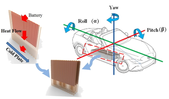
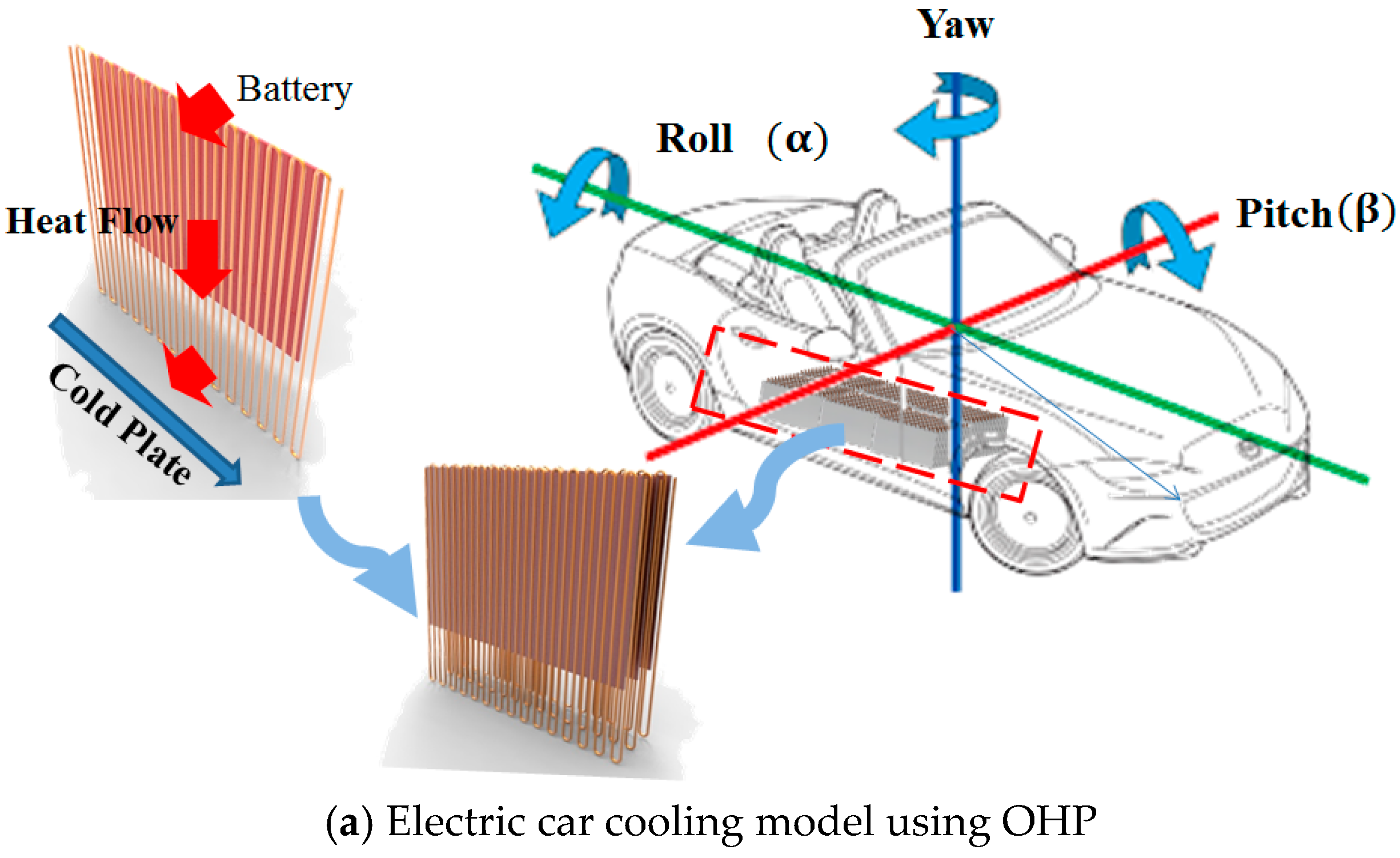
As shown in Figure 1, an oscillating heat pipe (OHP), also called a pulsating heat pipe (PHP), is proposed in the present study as a promising heat transfer technology for battery cooling due to its high heat transmitting performance with its simple wickless structure, compact size, and low manufacturing cost [21,22,23,24]. An OHP could be an ideal candidate for Li-ion battery cooling for future EVs compared to other conventional cooling technologies [25,26,27].
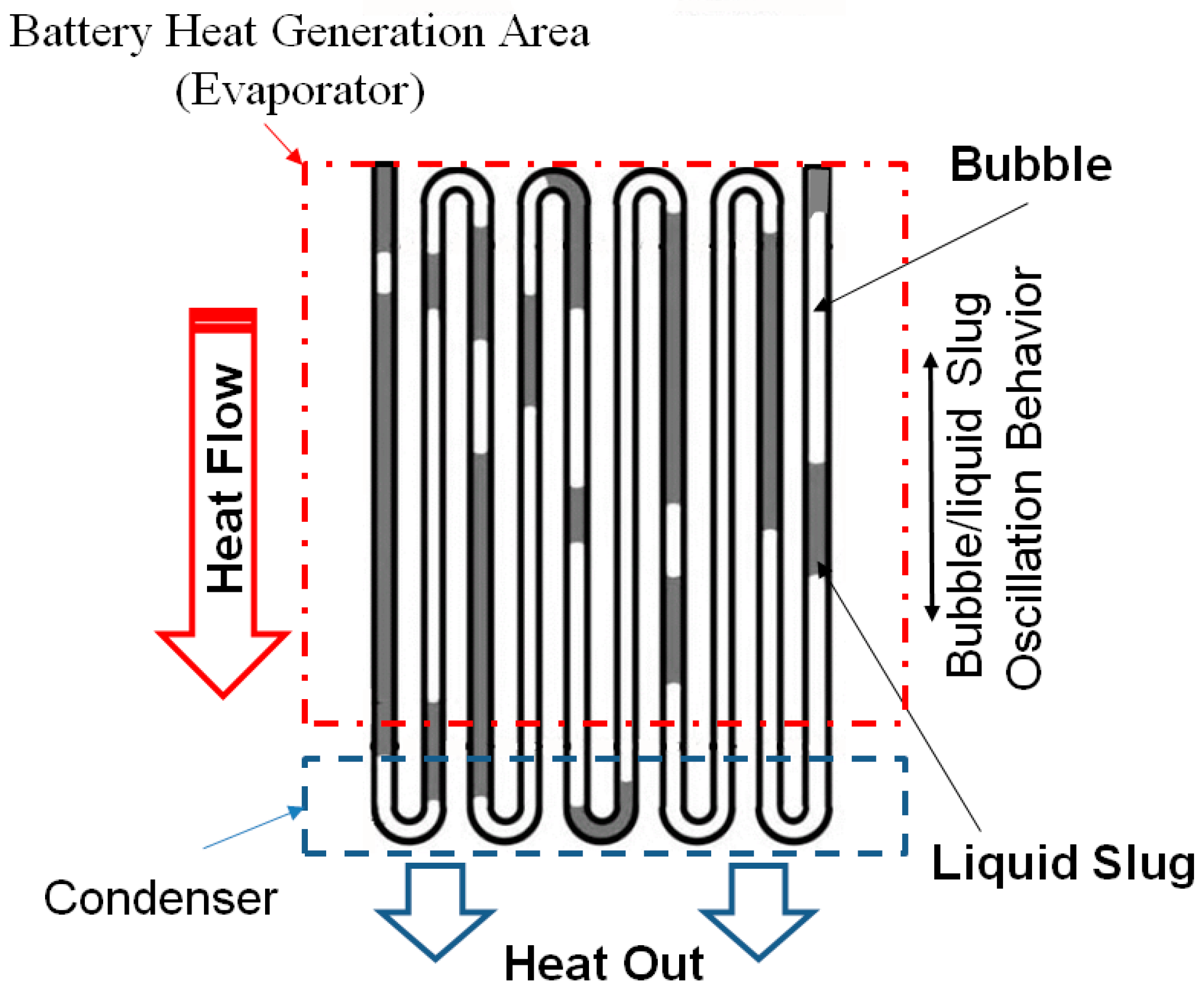
In 1990, Akachi in Japan invented this new heat transfer device, the OHP (or PHP). It consists of a curved channel and saturated working fluid, and can be divided into the evaporator, insulation, and condenser sections. In the operating state, the working fluid inside the OHP is separated by a liquid slug and a vapor plug [23], and when the heat is supplied to the heating section, the liquid slug starts to oscillate driven by the pressure difference along the flow path between the evaporator and the condenser [24]. This self-activated oscillation of the working fluid leads to the transfer of heat through the liquid slug. Subsequently, the liquid slug moves into the expansion or compression space of the vapor plug [25,26]. These oscillations in each channel affect each other and can be linked to the liquid slug and vapor plug motion.
In contrast with its simple structure, the operating mechanism of OHPs seems quite complicated and has been studied in theory and experimentally by many researchers. Such studies have mainly focused on the effects of various parameters, such as the tube diameter, filling ratio, inclination angle, number of turns, and working fluid properties; the its flow visualization.
Tong et al. [28], Qu et al. [29], Katpradit et al. [30], Xu et al. [31], Das et al. [32], and Soponpongpipat et al. [33] among others have investigated OHPs via visualization studies using glass tubes. They carried out experimental and analytical research to visualize their flow structure and liquid film behavior.
Ma et al. [34,35], Qu et al. [36,37], and Ji et al. [38] achieved higher heat transfer performance with a nanofluid as the working fluid in the OHP operation. In addition, many researchers [39,40,41,42,43,44,45,46,47] have attempted to investigate the effects of various parameters such as the tube diameter, the length of the evaporation section and the condensation section, the bend diameter, the number of turns, and the inclination angle. In addition, Wang et al. [48] conducted an experimental investigation on an OHP as a battery cooling system, but they used the bottom heating/top cooling method. However, due to the limited space available in the structure of EVs, the cooling channel should be installed under the battery, thus leading to more frequent battery maintenance and replacement.
The main objective of this paper is to investigate the heat transfer performance of an OHP to cool an EV’s Li-ion batteries, and thus to determine its operating mechanism at different input powers, charging ratios and inclinations. To achieve this objective, it is worthwhile to begin by providing an overall perspective on the principal ideas behind various cooling technologies for EVs. This will ascertain the relative position of OHPs as a heat transfer solution for EV’s battery cooling. Such OHPs should be designed to be operated with efficient cooling performance at any inclination angle. The inspiration for the present research is to find ways to achieve a high performance passive system as well as, to drastically reduce the manufacturing complexity involved in OHPs. The concept of an OHP cooling system is expected to addresses these issues [49,50]. In addition, we attempted to design a novel battery cooling system with top heating/bottom cooling with an OHP with a long evaporator section and a short condensing section.
2. Experiments
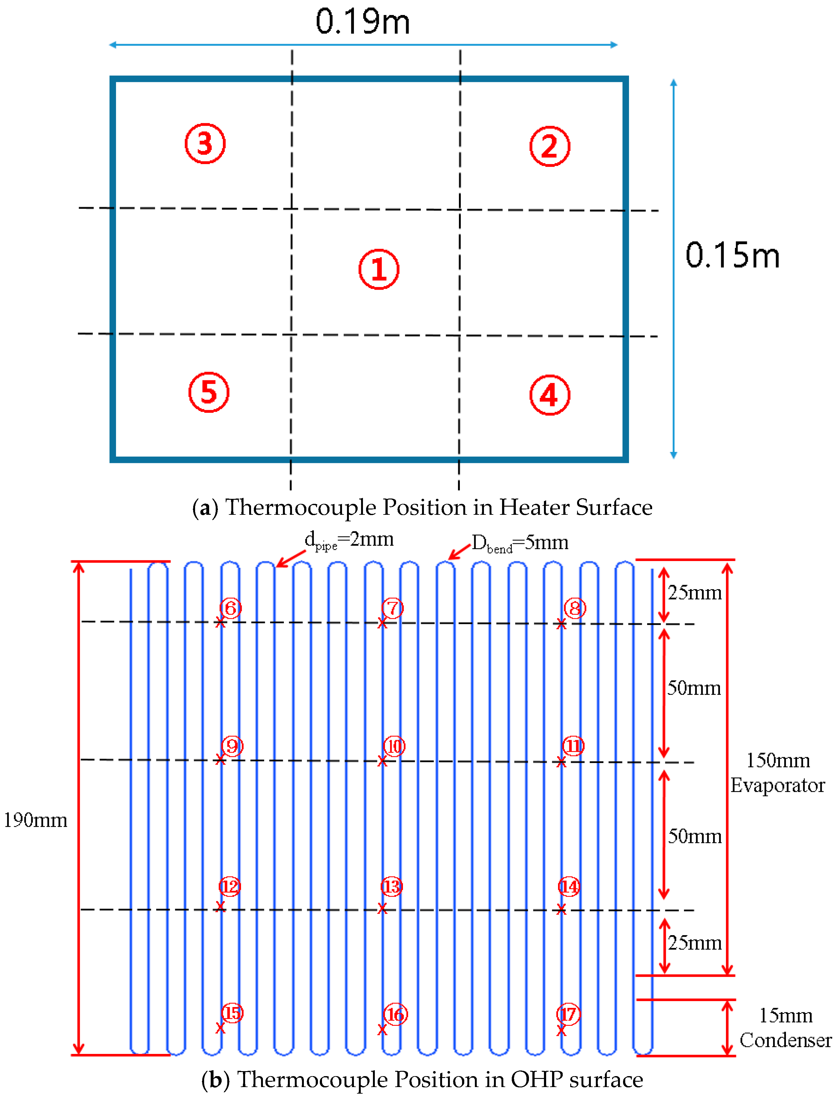
Figure 2a–c shows the present battery cooling system with OHP; it also shows the thermocouple positions. As shown in Figure 2a, the present OHP cooling system is an application for EV battery cooling. Therefore, in the experiment, appropriate working conditions were simulated for the OHP system, with rolling and pitching orientations. As shown in Figure 2b, the present OHP was fabricated by a copper capillary tube, divided into three parts: evaporator, adiabatic and condenser sections, with lengths of 190 mm. The total width with 15 turns of 2 mm outer diameter copper tube (0.5 mm thick wall) is less than the length of a heater. The experimental setup illustrated in Figure 2c mainly consists of an end-opened OHP assembly having 15 turns, a wired heating system, a water flowing cooling system, and a multichannel data acquisition system. The heater (190 mm × 150 mm) was used to simulate a Li-ion battery of an EV. It has been manufactured with a special design to simulate an EV’s rectangular pouch battery. The benchmarked model of the present cell heater was essentially a cell of a Hyundai hybrid car produced by LG Chem. Its nominal output power was 19.9 W. Heat generation rate is depending on discharging C-rate. In the present study, the extra high rate heat generation is not considered.
The thermostat providing a cooling water (0.01 kg/s, 23 °C) system was connected to a cooling water flowing channel (190 mm × 15 mm) comprised of aluminum alloy and with a wall thickness of 2.5 mm. To reduce heat losses, an extruded polystyrene (thickness = 10 mm) insulation plate covered both outer cover sides of the OHP and heater, respectively.
To sustain the shape of the liquid column inside the tube, the tube diameter of the OHP should meet the working criteria of the tube’s inner diameter described in Equation (1) [49]. When the working fluid is ethanol, this critical inner diameter is about 0.035 m. Therefore, the present 2 mm OD copper tube with 0.5 mm thickness is suitable for the operation limit of the OHP:
The present OHP is made of a copper tube (Di = 1 mm, Do = 2 mm); it has 15 turns, the bend curvature diameter is 5 mm, and the total volume of heat pipe inside is about 4.5 mL. The charged amount is described as the volume fraction (VF = ((charged volume of working fluid)/(total volume of the OHP)) 100) ratio compared to the total volume of the OHP. Its evaporator and condenser sections are attached to the heater and cooling channel, respectively, connected by a 25 mm long adiabatic section.
As shown in Figure 3, 19 K-type thermocouples (TT-K-36-SLE, Omega, Stamford, CT, USA) were installed and connected to the data acquisition module (MX-100, Yokogawa, Tokyo, Japan) to measure the temperature of the OHP cooling system. The accuracy of temperature measurement was ±(rgd 0.05% + 0.7).
As shown in Figure 3a,b, thermocouples were attached on the surface at 19 positions : Nos. 1–5 in five positions on the heater surface, Nos. 6–8 in the upper part on the evaporator surface of the OHP 25 mm away from the top end, Nos. 9–11 in the middle section of evaporator section with 50 mm pitch, Nos. 12–14 in the lower part of the evaporator section with a 50 mm pitch, Nos. 12–14 close to the 25 mm adiabatic section, Nos. 15–17 in the middle of the condensing section, and Nos. 18–19 in the coolant inlet and outlet. We used the DC power supply to adjust the power of the heater. The minimum scales of the ammeter and voltmeter are 0.01 A and 0.01 V, respectively. The working fluid of the OHP was anhydrous ethanol, and it was injected by a syringe into the OHP with a perfect vacuum of 10−5 torr. The minimum scale of the charging syringe was 0.01 mL.
To estimate the thermal performance of the present OHP system, the average temperature difference of the evaporator and effective thermal resistance was determined from steady-state data. The average temperature difference was computed by obtained experimental data as Equation (2):
where and are the average of all nine evaporator and three condenser temperatures, respectively. The thermal resistance is an important parameter indicating the thermal performance of an OHP; it is defined as shown in Equation (3) [45]:
where Q is the heating power input added to the evaporator, which is calculated by:
where V and I are the input voltage and electric current, respectively.
Experimental uncertainties of the direct measurement parameters such as T, V, and I were synthesized by the system uncertainty. According to the methods in [3], the maximum uncertainty of thermal resistance in this study was 3.2%.
3. Results and Discussion
In the present experimental study, the operation and performance of the OHP was associated with various parameters such as the supplied heat, amount of coolant charged, number of turns, tube diameter, tube length, heating and cooling length and inclination angle. The potential of using the OHP as a battery cooling module was verified.
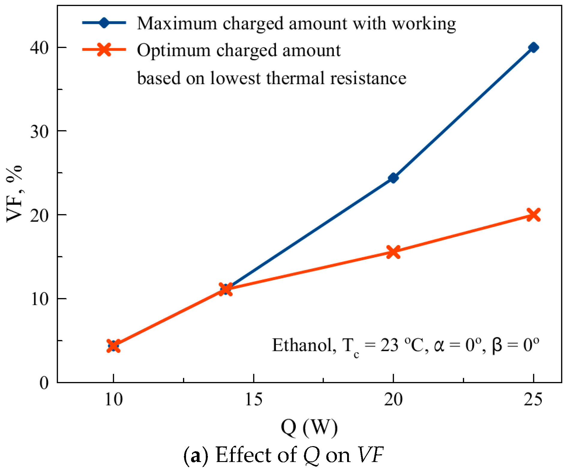
Figure 4a,b shows the experimental results with different charged amounts and supplied heats. As shown in Figure 4a, as the heat flux increased, the maximum charged amount (charging limit) and optimum charged amount showing the best performance increased. As illustrated in Figure 4b, the thermal resistance was decreased by increasing the heat flux and the charging amount; it decreased by VF = 15.6% (Q = 20 W) and VF = 20% (Q = 25 W), and after that, it increased again. This means that the OHP system requires an optimum charging amount to achieve the best heat transfer performance. In addition, it can be associated with oscillation behaviors. This trend on the effect of the charged amount is similar to the results of Lee [39].
This is because when the supplied heat is increased, the temperature difference between the evaporator and condensation sections is also increased. Thus, this leads to an increased pressure difference between bubbles. If the charged amount is insufficient, the working fluid cannot be sufficiently supplied to the vapor region of the heat pipe, resulting in a dry-out phenomenon. Since the liquid viscosity coefficient is much larger than vapor, in the case of a large amount of working fluid, the pressure drop will increase between the liquid and pipe wall, the motion of working fluid will be resisted, and then subsequently the thermal resistance will increase.
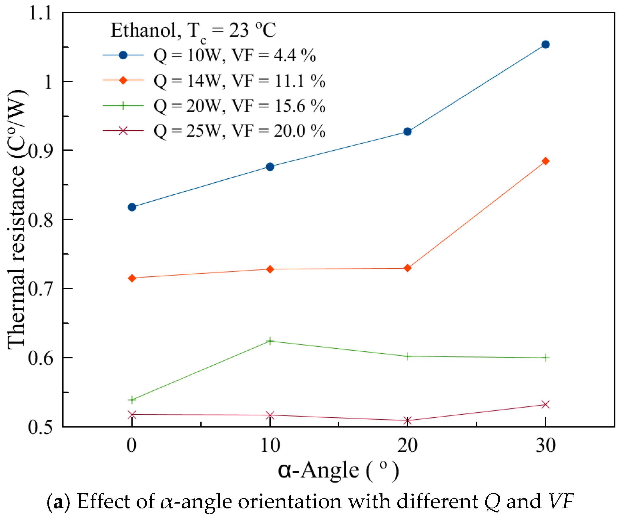
The present OHP system is a battery cooling application for EVs. Figure 5 shows the thermal resistance of the OHP with the heating and inclination angles with different charging ratio. As shown in Figure 5a,b, roughly increasing the -angle, the thermal resistance was increased. Especially in the case of a low heat flux (Q = 10~14 W), the thermal resistance was increased sharply with increasing the -angle. Conversely, in the case of high heat flux as Q = 20~25 W, the thermal resistance variation was not large with different -angles. As shown in Figure 5b, the -angle also influences the OHP performance. Similar to Figure 5a for the -angle, at a low heat flux (Q = 10 W), the thermal resistance increased sharply with increasing the -angle. This trend on the effect of is consistent with Rittidech’s [50] results based on top heating/bottom cooling.
At a low heat flux (Q = 10 W), thermal resistance is strongly influenced by increasing the heat flux with inclination angles of both This is due to the minimal pressure difference between hot and cold region induced from gravity effect of working fluid with increasing charged amount at low heat flux. In high heat flux it can be disappeared due to highly increased vapor pressure.
Figure 6, Figure 7 and Figure 8 show the transient temperature variations and power spectrum analysis. The temperature behavior of the wall surface close to the inlet (or outlet) of the evaporator section of the OHP is one of the most important factors to investigate the chaos that can be induced in the system. Thus, the temperature time series analysis (No. 13 as the surface close to the inlet (or outlet) of the evaporator section) is significant to analyze the chaotic oscillation of the OHP. In the present study, the OHP’s chaotic oscillatory behavior induced by various parameters, such as charging ratio, heat flux, and inclination was investigated. To analyze the time series of temperature fluctuations at a specific location on the OHP tube wall, power spectrum analysis using Fast Fourier Transform (FFT) was proposed [21]. In this work, No. 13 installed in the bottom of evaporator is dedicated to analyzing the interfacial work between the evaporator and condenser. The power spectrum density (PSD) approach is useful to investigate the data module of temperature time series. The PSD of a time series can explain the power distribution into frequency components.
The statistical average of a certain signal or sort of signal (including noise) as analyzed in terms of its frequency content is called its spectrum by signal analysis tool Origin 8.5. The PSD can be defined as Equation (5) [26,51]. By definition, PSD can be computed with the following equation:
where is the auto-correlation function of the input signal.
In the present FFT, to estimate the power spectrum with a finite number (about 5000–13,000 samples for the input signal), the periodogram method was used. It estimates the power as the mean squared amplitude (MSA) from the amplitude of the Fourier transformed data. The frequency column is obtained from the sampling interval and the number of input data points N. The nth frequency datum is given by:
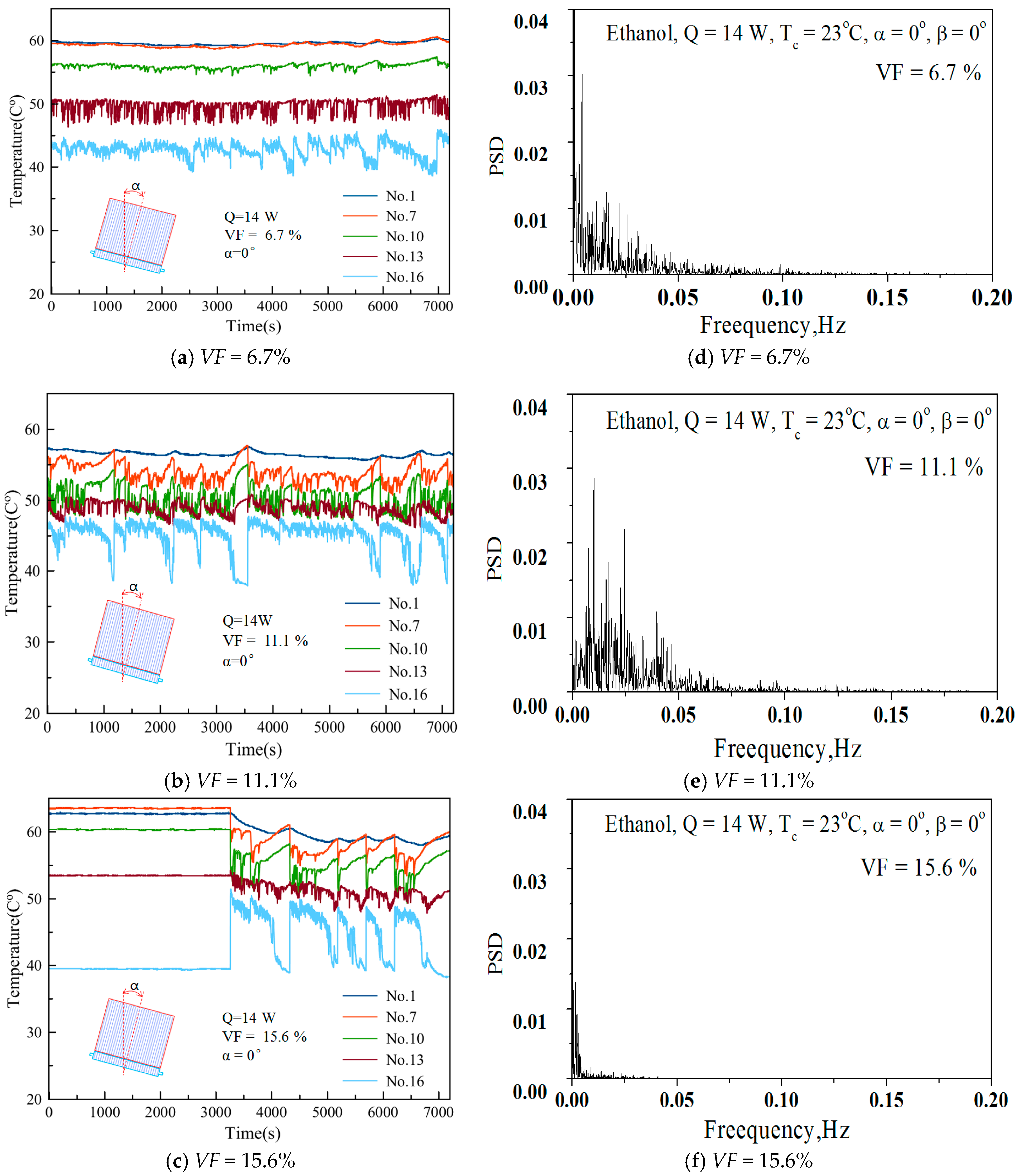
Figure 6a–c shows the transient temperature variation of the OHP system with 14 W (VF = 6.6%) heat supplied in vertical orientation. As shown in Figure 6a, Nos. 13 and 16 were oscillating in a certain range of amplitude and periodical wave, but Nos. 7 and 10 hardly vibrated. When the charged amount was VF = 11.1%, as shown in Figure 6b, all the thermocouples installed in the OHP system showed oscillatory temperature variations, and the temperature of the heater was reduced more than in the case of VF = 6.7%. When the charged amount was VF = 15.6%, the temperature oscillation of the OHP intermittently stopped. This could be due to the pressure adjusting time of the system. In addition, when the heater reached a certain temperature, the oscillatory operation was restarted, as shown in Figure 6c. This shows that the operating status of the OHP is closely related to the charged amount. Figure 6d–f show the time series of temperature fluctuations at No. 13 with VFs, and 14 W, condenser temperature of 23 °C, the filling ratio of VF = 6.6~15.6%, ethanol as the working fluid and its PSD diagram. The spectral analysis of the time series in Figure 6 indicates a dominant peak around frequencies of 0–0.1 Hz.
Figure 6d–f indicates an intense periodic or quasi-periodic oscillation of temperature at this dominant frequency with a PSD of 0.05 Hz with VF = 6.7%. The PSDs of oscillations at other frequencies are in an order to be neglected compared with this dominant peak. As shown in Figure 6d–f, when increasing the VF the PSD distribution was strongly reduced. This means that the system was unstable or had no oscillatory working behavior. Further, in the present OHP system, heat transfer was induced from repeated pressure fluctuations, and hence the strong cyclic pressure fluctuation means more heat transfer.
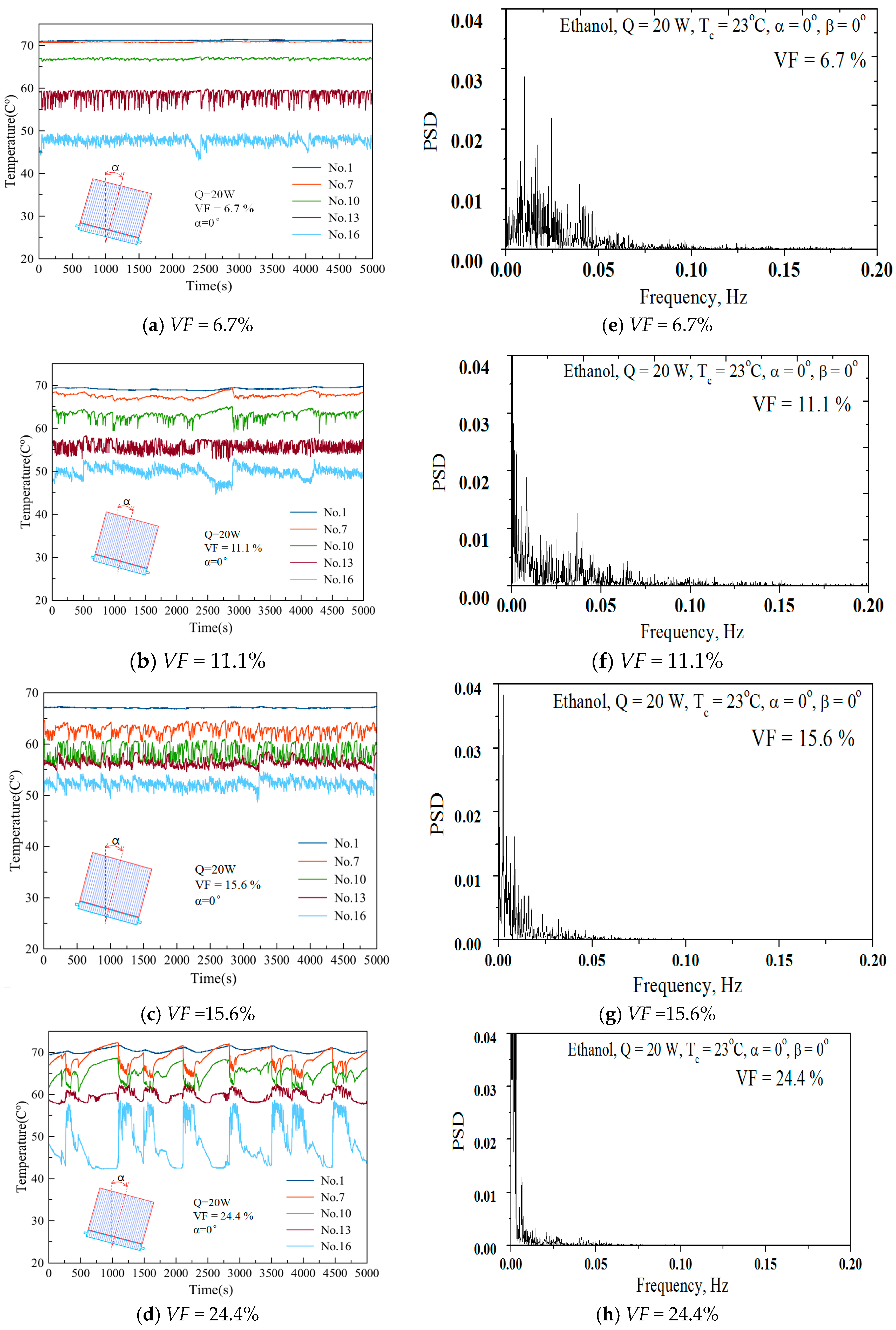
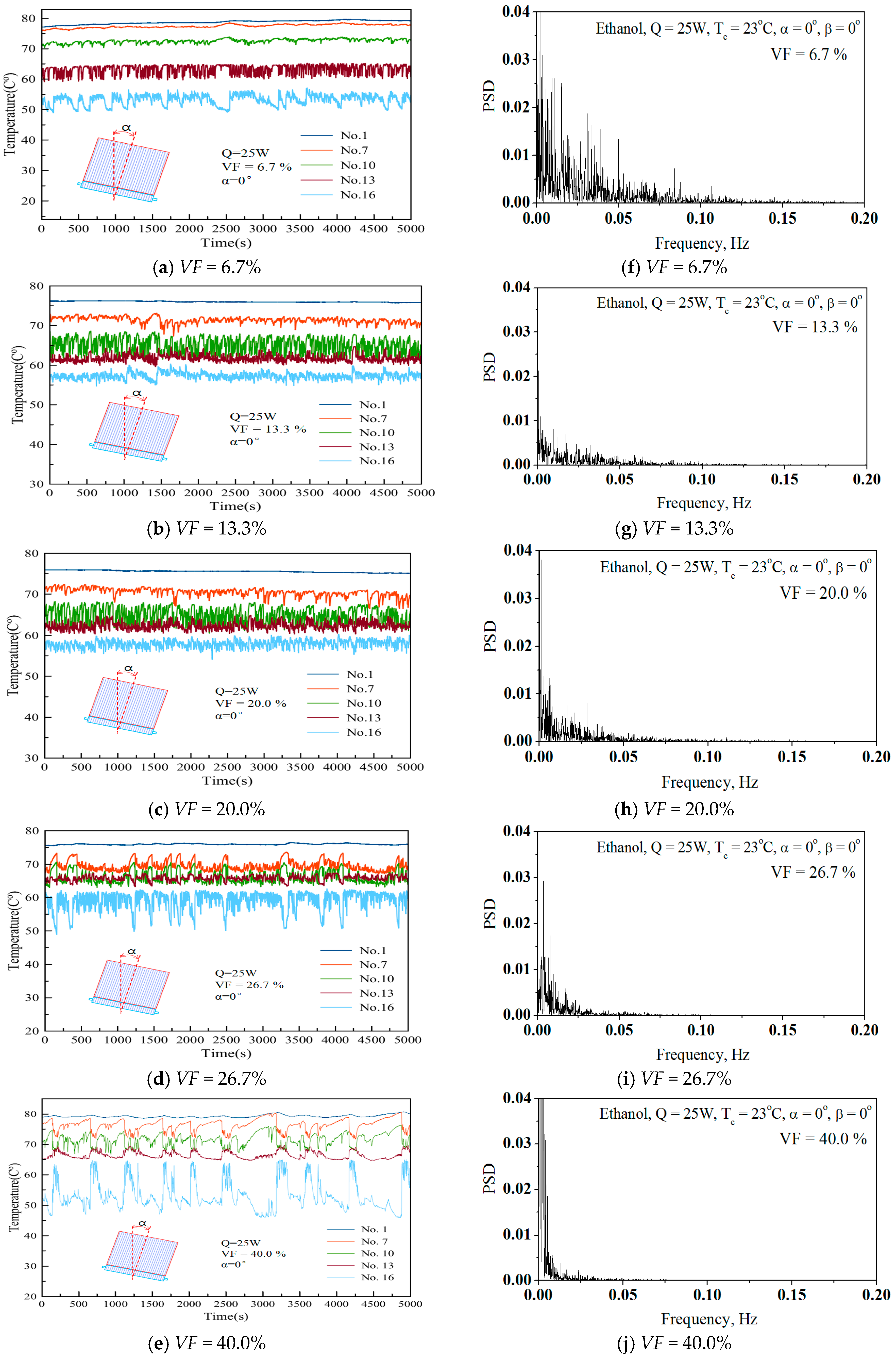
Like Figure 6, Figure 7 shows the individual frequency distribution for each applied filling ratio for 20 W heat input. For a VF = 6.7%, the filling ratio in Figure 7a, the PSD and frequency number are not as comprehensive, with many peaks of different magnitudes. This means that the OHP worked with potentially large chaotic temperature fluctuations. The PSD decreased with an increasing charging ratio and the frequency was nearly zero for large amounts of working fluid. This implies that the system was unstable with decreased oscillatory behavior. It is clear that the system was in stable oscillatory operation with a low charging ratio. Figure 8 shows the effect of the charging ratio with Q = 25 W. It is clear that the system needed a low charging rate to ensure proper oscillatory operation. As shown in Figure 6, Figure 7 and Figure 8, average heater surface temperatures for different heat fluxes were 46.67 °C for 10 W, 56.3 °C for Q = 14 W, for 65.3 °C for Q = 20 W, and 73.6 °C for Q = 25 W.
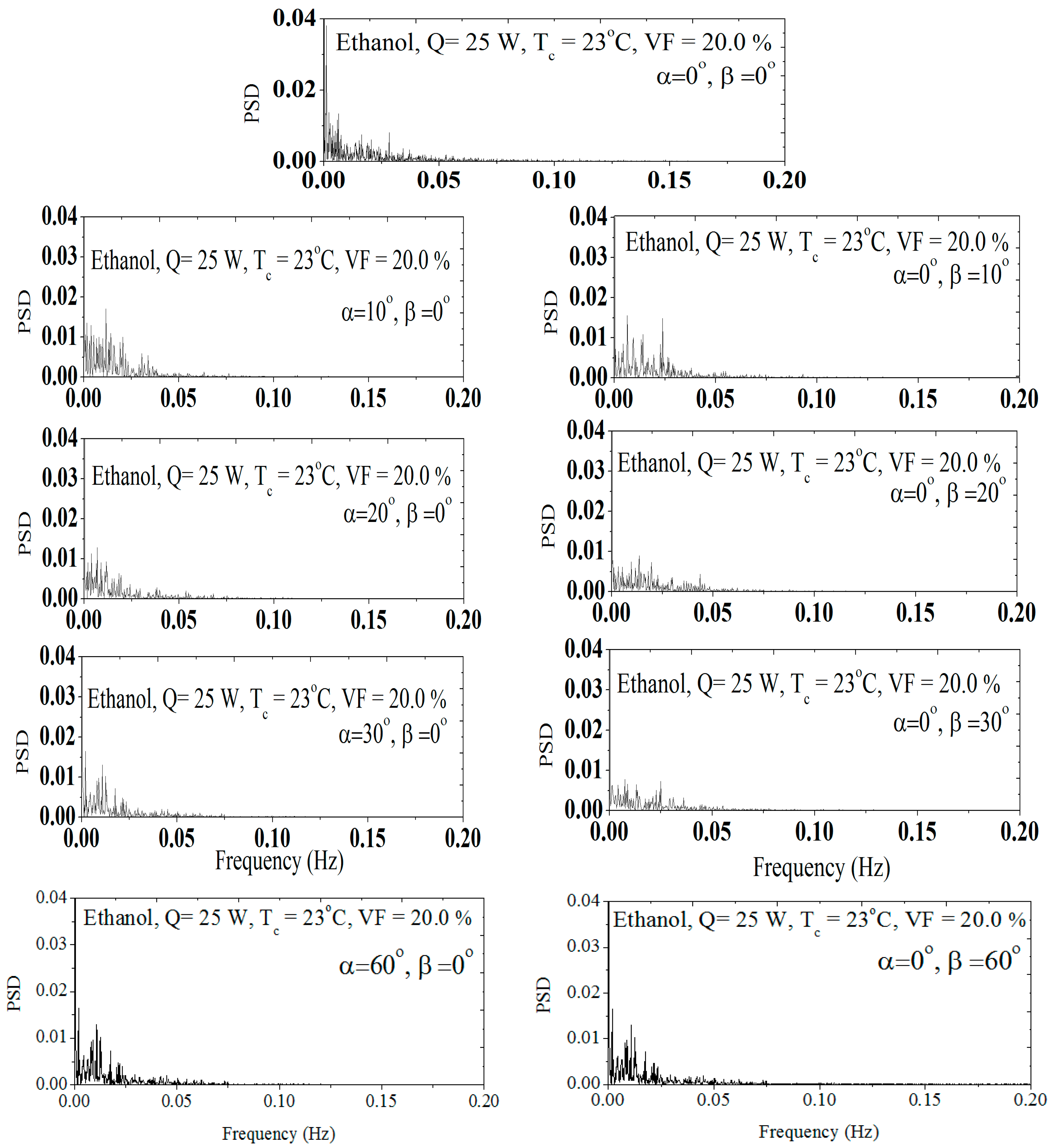
Figure 9 shows the PSD series of the wall temperature at No. 13 under a heating power of 25 W, a VF = 20% and a condenser temperature of 23 °C and ethanol as the working fluid and its PSD diagram with different α and β orientations. The PSD distribution with α and β orientations shows a very similar trend as shown in Figure 9. Increasing the α and β angles reduced the PSD distribution.
As explained above in Figure 6, Figure 7 and Figure 8, a decreased PSD and frequency distribution led to reduced thermal performance. It can be seen in Figure 9 that there are different PDF distributions and frequency spreading in the PSD diagram in the range of 0–0.1 Hz. Upon increasing orientation angles, it is evident that there is dominant peak in the PSD diagram. Moreover, the PSD decayed by the frequency increment. This indicates the chaotic state in the present OHP system. Thus, the PSD with different orientation in Figure 9 can be explained as chaos working states under the given operating conditions.
4. Conclusions
In the present study, the specially designed OHP has a 150 mm long evaporator section and a 15 mm short condensing section. The conclusions may be summarized as follows:
- -
- The thermal performance was mainly dominantly dependent on the amount of working fluid charged. The system worked properly with a low charged VF of around 10% of the total volume.
- -
- Increasing the heat input, the working range of the charged amount varied in the 10–26% range.
- -
- The optimum charged amount with supplied heat input should be determined by the thermal resistance behavior.
- -
- The α and β-angle inclination of the OHP system minimally influenced the thermal resistance with a high heat input, but at a low heat, the thermal resistance sharply increased when the α and β-angles increased. However, the working behavior with FFT analysis was not significantly affected by the orientation.
- -
- The average heater surface temperature was maintained around 60 °C for heat fluxes under Q = 20 W.
Acknowledgments
This research was supported by Basic Science Research Program through the National Research Foundation of Korea (NRF) funded by the Ministry of Education (No. NRF-2016R1D1A1B03930495).
Author Contributions
Ri-Guang Chi, worked for whole experiments and analysis. Won-Sik Chung supported the experiments. Seok-Ho Rhi advised as a supervisor for this research. And this research was managed and supported by Seok-Ho RHI.
Conflicts of Interest
The authors declare no conflicts of interest.
Nomenclature
| Dcr | Critical diameter [m] |
| Di | Inner diameter [m] |
| Do | Outer diameter [m] |
| Gravitational acceleration [m/s2] | |
| I | Electric current [A] |
| P | Power Spectrum Density [Energy/frequency] |
| Evaporator section of average temperature [°C] | |
| Temperature of cooling water [°C] | |
| Condition section of average temperature [°C] | |
| R | Thermal resistance [W/°C] |
| Heating of heater [W] | |
| Voltage [W] | |
| Volume fraction, ((Volume of charged working fluid)/ (Total volume of OHP))100 | |
| Greek Letters | |
| α | Rolling angle [°] |
| β | Pitching Angle [°] |
| σ | Turface Tension [N/m] |
| Density of liquid [kg/m³] | |
| Density of gas [kg/m³] | |
| Temperature difference [°C] |
References
- Cui, S.M. New Energy Vehicle Technology; Peking University Press: Beijing, China, 2009. [Google Scholar]
- Li, Y. Thermoelectric Power Generation Study-Based Automobile Exhaust Waste Heat Recovery; University of Electronic Science and Technology of China: Chengdu, China, 2010. [Google Scholar]
- China New Energy Chamber of Commerce. Hanergy, Global New Energy Development Report 2015; China New Energy Chamber of Commerce: Beijing, China, 2015. [Google Scholar]
- Linden, R.T.B. Handbook of Batteries; McGraw-Hill: New York, NY, USA, 2002; Volume 36, p. 265. ISBN 13 978-0071624213. [Google Scholar]
- Li, H.; Su, J. Cycle-life prediction model studies of lithium-ion batteries. Chin. J. Power Sources 2008, 32, 242–246. [Google Scholar]
- Panchal, S.; Dincer, I.; Agelin-Chaab, M.; Fraser, R.; Fowler, M. Experimental and theoretical investigations of heat generation rates for a water cooled LiFePO4 battery. Int. J. Heat Mass Transf. 2016, 101, 1093–1102. [Google Scholar] [CrossRef]
- Xu, X.; He, R. Review on the heat dissipation performance of battery pack with different structures and operation conditions. Renew. Sustain. Energy 2014, 29, 301–315. [Google Scholar] [CrossRef]
- Wang, T.; Tseng, K.; Zhao, J.; Wei, Z. Thermal investigation of lithium-ion battery module with different cell arrangement structures and forced air-cooling strategies. Appl. Energy 2014, 134, 229–238. [Google Scholar] [CrossRef]
- Mohammadian, S.K.; Zhang, Y. Thermal management optimization of an air cooled Li-ion battery module using pin-fin heat sinks for hybrid electric vehicles. J. Power Sources 2015, 273, 431–439. [Google Scholar] [CrossRef]
- Fan, L.; Khodadadi, J.; Pesaran, A. A parametric study on thermal management of an air-cooled lithium-ion battery module for plug-in hybrid electric vehicles. J. Power Sources 2013, 238, 301–312. [Google Scholar] [CrossRef]
- Giuliano, M.R.; Prasad, A.K.; Advani, S.G. Experimental study of an air-cooled thermal management system for high capacity lithium-titanate batteries. J. Power Sources 2012, 216, 345–352. [Google Scholar] [CrossRef]
- Zhao, J.; Rao, Z.H.; Huo, Y.; Liu, X.J.; Li, Y.M. Thermal management of cylindrical power battery module for extending the life of new energy electric vehicles. Appl. Therm. Eng. 2015, 85, 33–43. [Google Scholar] [CrossRef]
- Jin, L.; Lee, P.; Kong, X.; Fan, Y.; Chou, S. Ultra-thin minichannel LCP for EV battery thermal management. Appl. Energy Eng. 2014, 113, 1786–1794. [Google Scholar] [CrossRef]
- Huo, Y.; Rao, Z.; Liu, X.; Zhao, J. Investigation of power battery thermal management by using mini-channel cold plate. Energy Convers. Manag. 2015, 89, 387–395. [Google Scholar] [CrossRef]
- Panchal, S.; Dincer, I.; Agelin-Chaab, M.; Fraser, R.; Fowler, M. Uneven temperature and voltage distributions due to rapid discharge rates and different boundary conditions for series-connected LiFePO4 batteries. Int. Commun. Heat Mass Transf. 2017, 81, 210–217. [Google Scholar] [CrossRef]
- Putra, N.; Ariantara, B.; Pamungkas, R.A. Experimental investigation on performance of lithium-ion battery thermal management system using flat plate loop heat pipe for electric vehicle application. Appl. Therm. Eng. 2016, 99, 784–789. [Google Scholar] [CrossRef]
- Greco, A.; Cao, D.; Jiang, X.; Yang, H. A theoretical and computational study of lithium-ion battery thermal management for electric vehicles using heat pipes. J. Power Sources 2014, 257, 344–355. [Google Scholar] [CrossRef]
- Wang, Q.; Jiang, B.; Xue, Q.F.; Sun, H.L.; Li, B. Experimental investigation on EV battery cooling and heating by heat pipes. Appl. Therm. Eng. 2015, 88, 54–60. [Google Scholar] [CrossRef]
- Zhao, J.; Lv, P.; Rao, Z. Experimental study on the thermal management performance of phase change material coupled with heat pipe for cylindrical power battery pack. Exp. Therm. Fluid Sci. 2017, 82, 182–188. [Google Scholar] [CrossRef]
- Ye, Y.; Saw, L.H.; Shi, Y.; Tay, A.A.O. Numerical analyses on optimizing a heat pipe thermal management system for lithium-ion batteries during fast charging. Appl. Therm. Eng. 2015, 86, 281–291. [Google Scholar] [CrossRef]
- Akachi, H. Structure of a Heat Pipe. U.S. Patent No. 4921041, 1 May 1990. [Google Scholar]
- Akachi, H. Pulsating Heat Pipes. In Proceedings of the 5th International Heat Pipe Symposium, Melbourne, Australia, 17–20 November 1996; pp. 208–217. [Google Scholar]
- Khandekar, S. An Insight into Thermos-Hydrodynamic Coupling in Closed Loop PHPs. Int. J. Therm. Sci. 2004, 43, 13–20. [Google Scholar] [CrossRef]
- Miyazaki, Y. Oscillatory Flow in the OHP. In Proceedings of the 11th IHPC, Tokyo, Japan, 12–16 September 1999; pp. 367–372. [Google Scholar]
- Shafii, M.B.; Faghri, A. Thermal Modeling of Unlooped and Looped PHPs. J. Heat Transf. 2001, 123, 1159–1172. [Google Scholar] [CrossRef]
- Nikolayev, V. A Dynamic Film Model of the Pulsating Heat pipe. J. Heat Transf. 2011, 113, 081504. [Google Scholar] [CrossRef]
- Nikolayev, V. Oscillatory Instability of the Gas-Liquid Meniscus in a Capillary under the Imposed Temperature Difference. Int. J. Heat Mass Transf. 2013, 64, 313–321. [Google Scholar] [CrossRef]
- Tong, B.Y.; Wong, T.N.; Ooi, K.T. Closed-loop pulsating heat pipe. Appl. Therm. Eng. 2001, 21, 1845–1862. [Google Scholar] [CrossRef]
- Qu, W.; Ma, T. Experimental investigation on flow and heat transfer of a pulsating heat pipe. In Proceedings of the 12th International Heat Pipe Conference, Grenoble, France, 8–23 August 2002; pp. 226–231. [Google Scholar]
- Katpradit, T.; Wongratanaphisan, T.; Terdtoon, P.; Ritthidech, S.; Chareonsawan, P.; Waowaew, S. Effect of aspect ratios and bond number on internal flow patterns of closed end oscillating heat pipe at critical state. In Proceedings of the 13th International Heat Pipe Conference (13th IHPC), Shanghai, China, 21–25 September 2004; pp. 298–303. [Google Scholar]
- Xu, J.L.; Li, Y.X.; Wong, T.N. High speed flow visualization of a closed loop pulsating heat pipe. Int. J. Heat Mass Transf. 2005, 48, 3338–3351. [Google Scholar] [CrossRef]
- Das, S.P.; Nikolayev, V.S.; Lefevre, F.; Pottier, B.; Khandekar, S.; Bonjour, J. Thermally induced two-phase oscillating flow inside a capillary tube. Int. J. Heat Mass Transf. 2010, 53, 3905–3913. [Google Scholar] [CrossRef]
- Soponpongpipat, N.; Sakulchangsatjatai, P.; Saiseub, M.; Terdtoon, P. Time response model of operational mode of closed-loop oscillating heat pipe at normal operating condition. In Proceedings of the 8th International Heat Pipe Symposium, Kumamoto, Japan, 24–27 September 2006; pp. 291–296. [Google Scholar]
- Ma, H.B.; Wilson, C.; Borgmeyer, B.; Park, K.; Yu, Q.; Choi, S.U.S.; Tirumala, M. Effect of nanofluid on the heat transport capability in an oscillating heat pipe. Appl. Phys. Lett. 2006, 88, 143116. [Google Scholar] [CrossRef]
- Ma, H.B.; Wilson, C.; Yu, Q.; Park, K.; Choi, S.U.S.; Tirumala, M. An experimental investigation of heat transport capability in a nanofluid oscillating heat pipe. J. Heat Transf. 2006, 128, 1213–1216. [Google Scholar] [CrossRef]
- Qu, J.; Wu, H.; Cheng, P. Thermal performance of an oscillating heat pipe with Al2O3-water nanofluids. Int. Commun. Heat Mass Transf. 2010, 37, 111–115. [Google Scholar] [CrossRef]
- Qu, J.; Wu, H. Thermal performance comparison of oscillating heat pipes with SiO2/water and Al2O3/water nanofluids. Int. J. Therm. Sci. 2011, 50, 1954–1962. [Google Scholar] [CrossRef]
- Ji, Y.; Wilson, C.; Chen, H.H.; Ma, H.B. Particle shape effect on heat transfer performance in an oscillating heat pipe. Nanoscale Res. Lett. 2011, 6, 296. [Google Scholar] [CrossRef] [PubMed]
- Lee, J.S. Effect of Heat Flux and Filling Ratio on the Thermal Performance of a Pulsating Heat Pipe; Korea Advanced Institute of Science and Technology: Daejeon, Korea, 2012. [Google Scholar]
- Lin, Z.; Wang, S.; Chen, J.; Huo, J.; Hu, Y.; Zhang, W. Experimental study on effective range of miniature oscillating heat pipes. Appl. Therm. Eng. 2011, 31, 880–886. [Google Scholar] [CrossRef]
- Charoensawan, P.; Terdtoon, P. Thermal performance of horizontal closed-loop oscillating heat pipes. Appl. Therm. Eng. 2008, 28, 460–466. [Google Scholar] [CrossRef]
- Lin, Z.; Wang, S.; Ryo, S.; Zhang, L.W. Simulation of a miniature oscillating heat pipe in bottom heating mode using CFD modeling. Int. J. Heat Mass Transf. 2013, 57, 642–656. [Google Scholar] [CrossRef]
- Yang, H.M.; Zhang, C.; Manfred, G. Comparison between Two kinds of Pulsating Heat Pipes (Circle Tube Type and Flat Plate Type with square Channels). Fluid Mach. 2009, 37, 70–72. [Google Scholar]
- Wang, S.F. Effect of Length Ratio of Heating Section to Cooling Section on Properties of Oscillating Heat Pipe. J. South China Univ. Technol. (Nat. Sci. Ed.) 2007, 35, 59–62. [Google Scholar]
- Cao, X.L.; Wang, W.; Chen, J.; Li, X.L.; Yu, S.X. Experimental Investigation on the Start-Up Characteristic of a Pulsating Heat Pipe. Fluid Mach. 2009, 37, 57–60. [Google Scholar]
- Charoensawan, P.; Khandekar, S.; Groll, M. Closed loop pulsating heat pipes: Part A: Parametric experimental investigations. Appl. Therm. Eng. 2003, 23, 2009–2020. [Google Scholar] [CrossRef]
- Han, S.H.; Choi, J.W.; Kim, S.C. Computational analysis of thermal flow with varying the diameter and the number of tubes in pulsating heat pipes. J. Comput. Fluids Eng. 2016, 21, 86–93. [Google Scholar] [CrossRef]
- Wang, Q.C.; Rao, Z.H.; Huo, Y.T.; Wang, S.F. Thermal performance of phase change material/oscillating heat pipe-based battery thermal management system. Int. J. Therm. Sci. 2016, 102, 9–16. [Google Scholar] [CrossRef]
- Khandekar, S.; Groll, M. On the definition of pulsating heat pipes: An overview. In Proceedings of the 5th Minsk International Seminar (Heat Pipes, Heat Pumps and Refrigerators), Minsk, Belarus, 8–11 September 2003. [Google Scholar]
- Rittidech, S.; Terdtoon, P.; Tankakom, P. Evaporation and Working Fluid Properties on Heat Transfer Characteristic of a Closed- end Oscillating Heat Pipe. In Proceedings of the 6th International Heat Pipe Symposium, Chiang Mai, Thailand, 5–9 November 2000. [Google Scholar]
- OriginLab Corp. Help Manual. Available online: https://www.originlab.com/doc/Origin-Help/FFT1-Algorithm (accessed on 13 March 2018).
Figure 1.
Oscillating heat pipe (OHP).

Figure 2.
Experimental System.

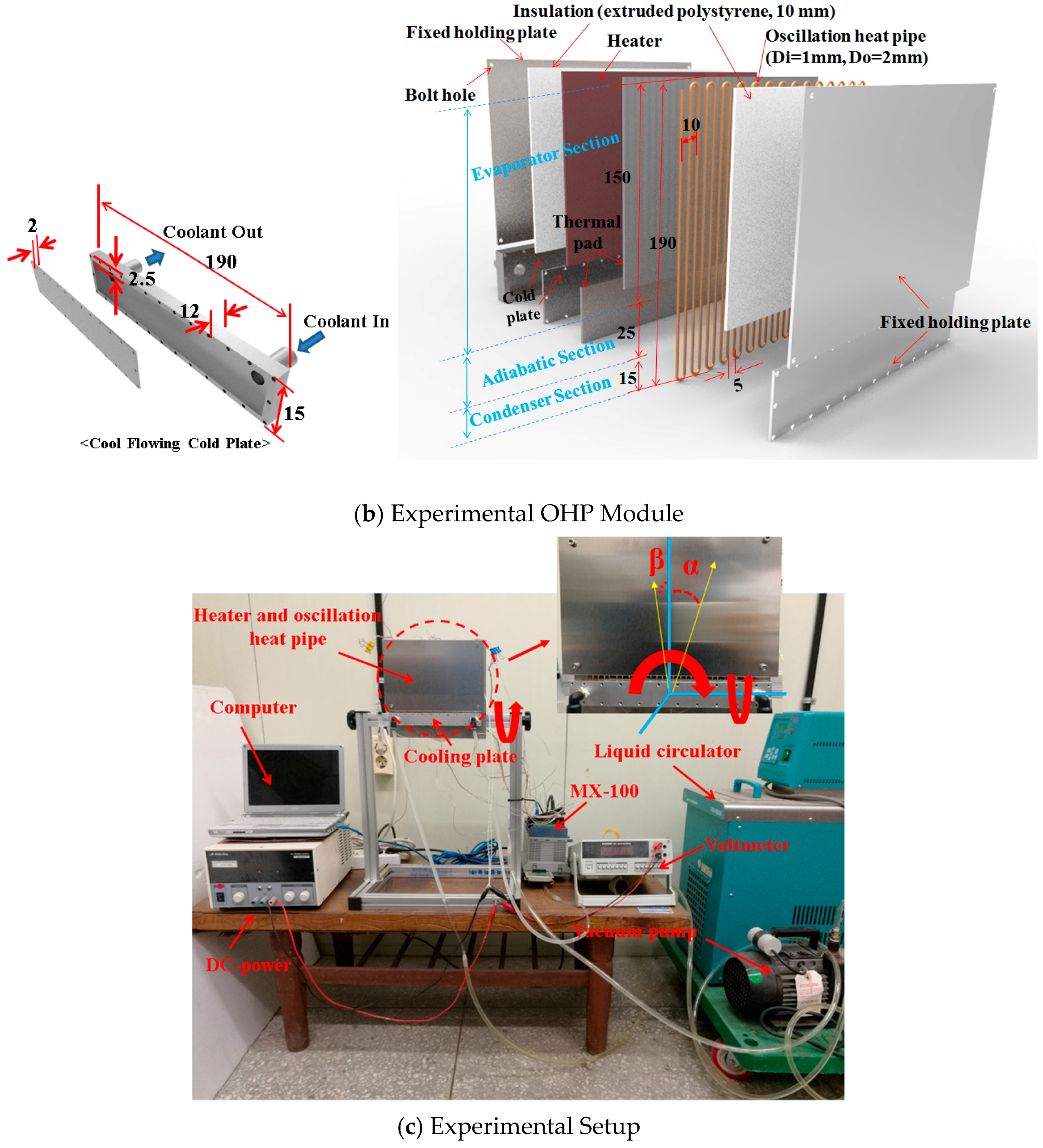
Figure 3.
Thermocouple Positions.

Figure 4.
Effect of Charged Amount (VF: Volume Fraction) on thermal resistance.

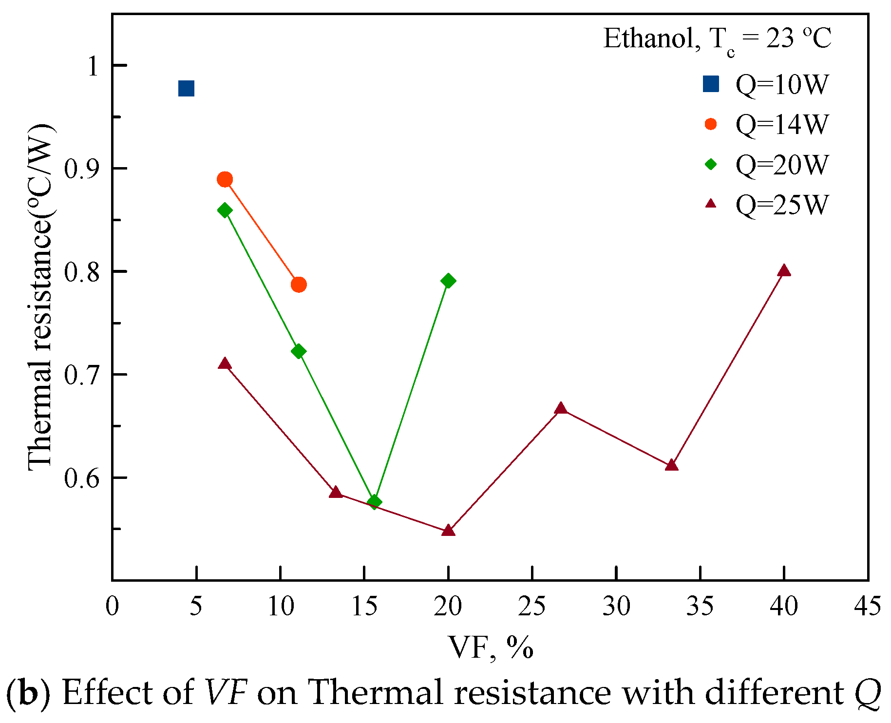
Figure 5.
Effect of Orientation with different Q and VF.

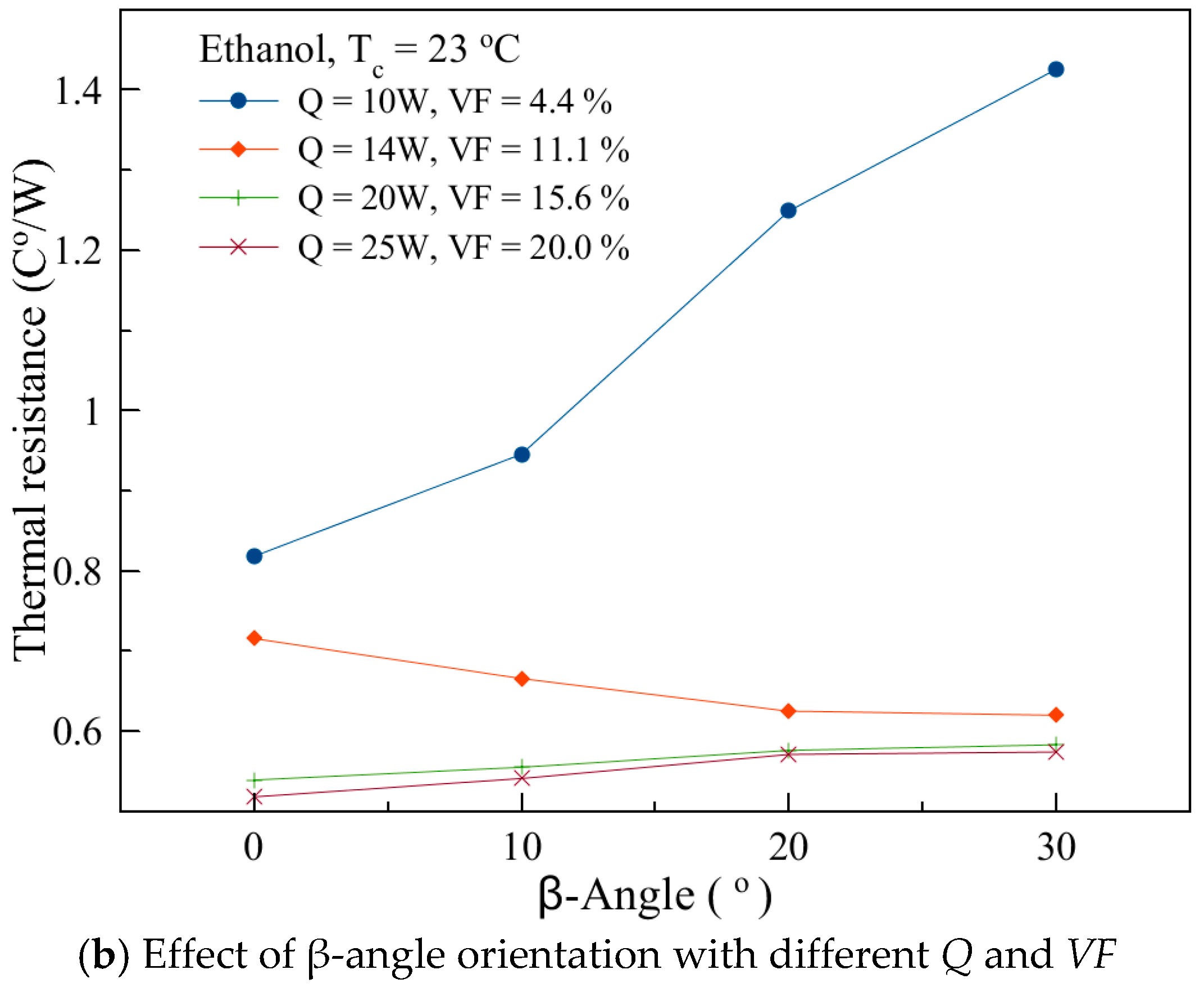
Figure 6.
Transient Temperature Variation and FFT PSD Distribution (#No. 13), Q = 14 W.

Figure 7.
Transient Temperature Variation and FFT PSD Distribution (#No. 13), Q = 20 W.

Figure 8.
Transient Temperature Variation and FFT PSD Distribution (#No. 13), Q =25 W.

Figure 9.
FFT PSD Distribution with Different Orientation (#No. 13), Q = 25 W.

© 2018 by the authors. Licensee MDPI, Basel, Switzerland. This article is an open access article distributed under the terms and conditions of the Creative Commons Attribution (CC BY) license (http://creativecommons.org/licenses/by/4.0/).
Share and Cite
MDPI and ACS Style
Chi, R.-G.; Chung, W.-S.; Rhi, S.-H. Thermal Characteristics of an Oscillating Heat Pipe Cooling System for Electric Vehicle Li-Ion Batteries. Energies 2018, 11, 655. https://doi.org/10.3390/en11030655
AMA Style
Chi R-G, Chung W-S, Rhi S-H. Thermal Characteristics of an Oscillating Heat Pipe Cooling System for Electric Vehicle Li-Ion Batteries. Energies. 2018; 11(3):655. https://doi.org/10.3390/en11030655
Chicago/Turabian StyleChi, Ri-Guang, Won-Sik Chung, and Seok-Ho Rhi. 2018. "Thermal Characteristics of an Oscillating Heat Pipe Cooling System for Electric Vehicle Li-Ion Batteries" Energies 11, no. 3: 655. https://doi.org/10.3390/en11030655
Note that from the first issue of 2016, this journal uses article numbers instead of page numbers. See further details here.