Comparative Study of Electric Energy Storages and Thermal Energy Auxiliaries for Improving Wind Power Integration in the Cogeneration System


School of Electrical Engineering, Wuhan University, Wuhan 430072, China
*
Author to whom correspondence should be addressed.
Energies 2018, 11(2), 263; https://doi.org/10.3390/en11020263
Submission received: 13 December 2017
/
Revised: 30 December 2017
/
Accepted: 18 January 2018
/
Published: 23 January 2018
(This article belongs to the Special Issue Energy Production Systems)
Abstract
:In regards to the cogeneration system in Northern China, mainly supported by combined heat and power (CHP) plants, it usually offers limited operation flexibility due to the joint production of electric and thermal power. For that large-scale wind farms included in the cogeneration system, a large amount of wind energy may have to be wasted. To solve this issue, the utilization of the electric energy storages and the thermal energy auxiliaries are recommended, including pumped hydro storage (PHS), compressed air energy storage (CAES), hydrogen-based energy storage (HES), heat storage (HS), electric boilers (EB), and heat pumps (HP). This paper proposes a general evaluation method to compare the performance of these six different approaches for promoting wind power integration. In consideration of saving coal consumption, reducing CO2 emissions, and increasing investment cost, the comprehensive benefit is defined as the evaluation index. Specifically, a wind-thermal conflicting expression (WTCE) is put forward to simplify the formulation of the comprehensive benefit. Further, according to the cogeneration system of the West Inner Mongolia (WIM) power grid, a test system is modelled to perform the comparison of the six different approaches. The results show that introducing the electric energy storages and the thermal energy auxiliaries can both contribute to facilitating wind power integration, and the HP can provide the best comprehensive benefit.
1. Introduction
The power system in Northern China is mainly dependent on coal-fired combined heat and power (CHP) units, which produce electric power in conjunction with thermal power [1]. In the present work, this kind of power system is broadly defined as the cogeneration system [2]. Since the power production of the CHP units is constrained by the heat demand, the cogeneration system may have a limited operational flexibility. Note that, since a large number of wind farms have been built in the nonflexible cogeneration system in Northern China [3], wind power curtailment is a significant issue to be dealt with. In a sense, a potential solution is to employ additional equipment whose expected functions are to improve the flexibility of the power system and reduce the curtailment of wind power. Considering the practical situation of Northern China, both electric energy storages [4,5] and thermal energy auxiliaries [6,7] can be appreciatively applied. For electric energy storages, their essential functions are to directly consume the surplus wind power. For thermal energy auxiliaries, they are able to provide extra thermal power and liberate the CHP units from heat demand, and then the electric power output of the CHP units can be further reduced. Thus, more wind power can be allowable for integration into the power grid.
Many studies have explored the benefits of electric energy storages for promoting the utilization of wind power. The effectiveness of the pumped hydro storage (PHS) for consuming surplus wind power was verified in [8,9,10]. Cost-optimal capacity of the PHS was studied in [11,12], a simulation platform was designed for optimizing the PHS capacity. Gu et al. in [13] and Cleary et al. in [14] evaluated the performance of the compressed air energy storage (CAES) in the system with significant renewable energy production, and stated that the CAES was the most attractive energy storage to be deployed at the utility scale, except for the PHS. The PHS and the CAES were used to store the excess renewable energy in [15], and this can contribute to reducing the operational cost of the conventional generators. In previous studies [16,17], the “Power-to-Gas” technology is regarded as the promising option for large-scale energy storage, except for the PHS and CAES. The studies of the “Power-to-Gas” energy storage, also named as hydrogen-based energy storage (HES), were performed in [18,19,20], which covered the accommodation of curtailed wind power, suppression of the wind power fluctuation, and advanced the control method of the wind power system. In these references, fuel cells were regarded as the best partner for the utilization of hydrogen. In addition, there are some reports focusing on battery energy storage (BES), magnetic energy storage (SMES), and flywheel energy storage (FES) [21,22,23,24]. Their cooperation with renewable energy sources for the promotion of the system performance has been preliminarily confirmed.
For the application of thermal energy auxiliaries in facilitating the wind power integration in the cogeneration system, related studies of heat storage (HS), electric boilers (EB), and heat pumps (HP) were reported in [25,26,27], and their positive effects were well verified in the Nordic countries. The HS was proved to be effective on the improvement of the system flexibility in [28]. Yu et al. proposed a linear optimization model to handle the scheduling problem of the cogeneration system with the HS [29]. Liu et al. investigated the optimal capacity of the EB by considering multiple system constraints [30]. The demonstrated results provided a good reference for studying the comprehensive benefit coupled with the EB. The cooperation of CHP plants with EBs and energy storages in micro energy grids was explored in [31], focusing on the optimal planning problems. The HP is actuated by renewable energy for district heating in [32,33], and the utilization efficiency of renewable energy is effectively enhanced. In addition, utilizing different kinds of heating devices might be a possible choice [34,35,36], but this kind of approach should consider an increased difficulty of scheduling management.
From the abovementioned references, electric energy storages and thermal energy auxiliaries have different theoretical effects on improving the wind power integration in the cogeneration system, and their application values have been confirmed to a certain extent. Note that the existing reports generally focused on the comparison for pure electric energy storages [37,38,39] or thermal energy auxiliaries [40,41,42], and only a few scholars carried out the comparative analysis of electric energy storages and thermal energy auxiliaries [43,44]. Very few works contributed to the general evaluation method, which was applicable to these two kinds of additional equipment, and conducted a systematic comparison in the cogeneration system with the high penetration of wind power. Moreover, since calculating the capacities of the electric energy storages and thermal energy auxiliaries is crucial to the evaluation, and the existing methods are too complex to be employed [11,12,30,45], it is of significance to propose a feasible and efficient approach to calculating the capacities of the two kinds of additional equipment.
Aiming at the above issues, this paper considers the utilization of different electric energy storages and thermal energy auxiliaries, including PHS, CAES, HES, HS, EB, and HP. In this study, a wind-thermal conflicting expression (WTCE) is proposed to quantify the contradiction between district heating and peak-shaving for wind power integration, and it is regarded as a critical factor to find a fast solution of the required capacities of electric energy storages and thermal energy auxiliaries. Further, the comprehensive benefit is defined as the indicator to evaluate the performance of the additional equipment, and the impacts of these additional equipment on the CHP units and wind power accommodation are studied in detail.
This paper is organized as follows: Section 2 states the function of the electric energy storages and thermal energy auxiliaries in the cogeneration system, and puts forward a formulation method for the comprehensive benefit of each equipment. In Section 3, the West Inner Mongolia (WIM) power grid is selected to conduct case studies, and related calculations and discussions are carried out. In Section 4, conclusions are given and some following-up plans are suggested.
2. Methodology
2.1. Operation Characteristic of Combined Heat and Power (CHP) Units
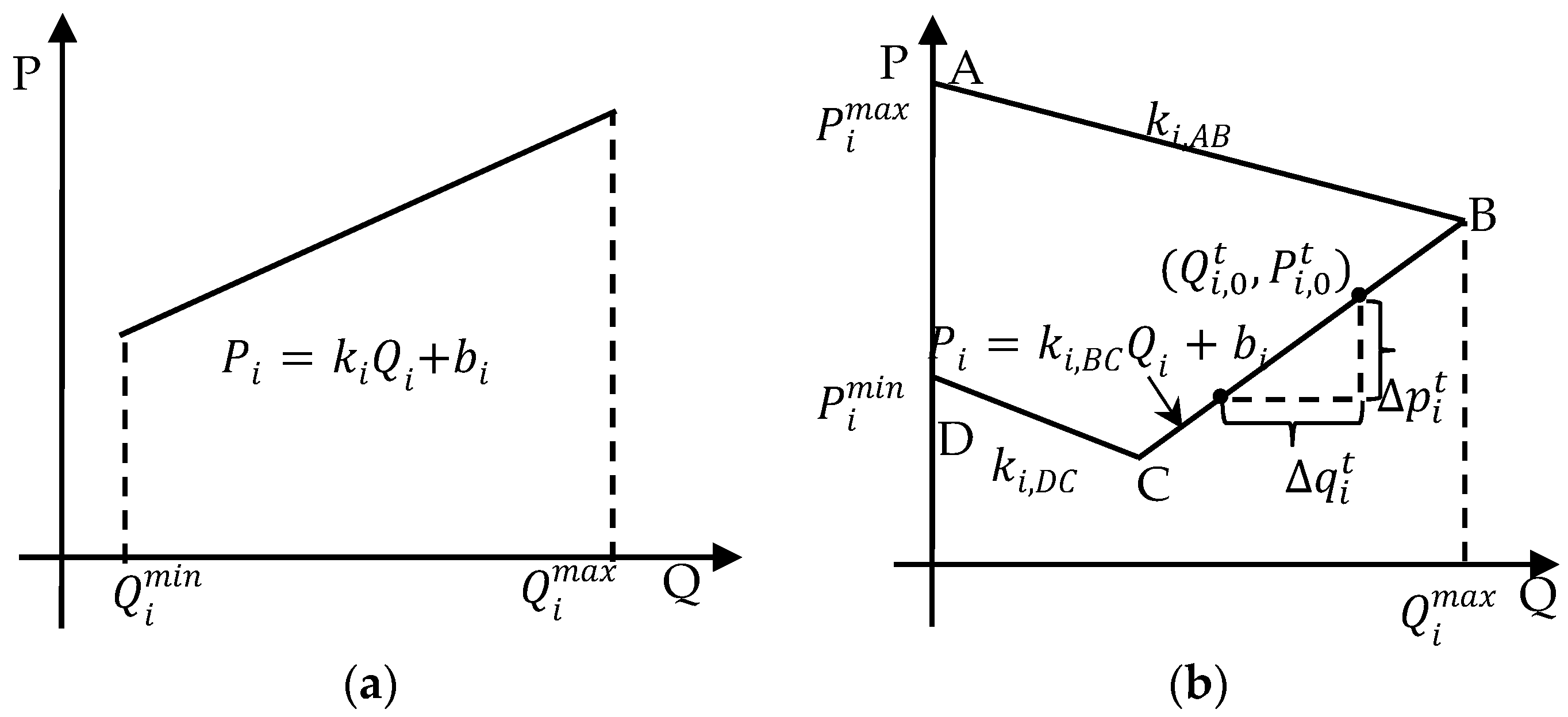
The CHP units are classified as back-pressure units and extraction-condensing units. As shown in Figure 1a, the produced electric power of the back-pressure units depends linearly on the output of the thermal power, thus leading to a limited operation flexibility. For the extraction-condensing units, the operation region in Figure 1b is described as an irregular quadrilateral [46]. Obviously, the feasible operation region of the extraction-condensing units is much bigger than that of the back-pressure units. In fact, a majority of the CHP units belong to the extraction-condensing units in Northern China [47], and this kind of CHP is selected to conduct the theoretical analysis as follows.
As shown in Figure 1b, the operation zone of the CHP unit can be formulated as a set of inequalities:
where , , and are the slopes of the segments DC, BC, and AB, respectively.
In winter, the CHP units are forced to serve as the source of district heating, and they usually operate at the minimum condensing steam state, which is labeled as the segment BC in Figure 1b. The coupling relationship between the outputs of the thermal power and the electric power is expressed as ). The thermal power output of the CHP units is adjusted to follow the heat load, and the electric power production is constrained by the thermal power. This operating characteristic greatly limits the flexibility of the CHP units. More details about the operating principle of the CHP units can be found in [48].
2.2. Wind-Thermal Conflicting Expression (WTCE)
It is assumed that, when the curtailment of wind power occurs at time t, the i-th CHP unit operates at the point , and other plants in the system operate at the minimum power output. If the wind power curtailment is expected to be reduced, the electric power output of the CHP units has to be cut down, and accordingly, the produced thermal power is supposed to be decreased. The reduced thermal power and electric power of the i-th CHP unit are denoted as and , respectively, and the increased integration of wind power is expressed as:
where and are the wind power integration before and after the CHP units play the role, respectively; is the increased amount of wind power integration.
Although the wind power integration is promoted, the cogeneration system suffers from the shortage of supplied thermal power. Thus, the WTCE is defined as the confliction between wind power integration and heating supply. In consideration of the relationship between and , the WTCE is derived as:
where is the insufficient heating power which can be supported by additional heating devices.
The WTEC is a critical factor in calculating the capacities of the additional equipment for the reason that the capacities of the electric energy storages are determined by the , and the capacities of the thermal energy auxiliaries are bounded by . Details about the method will be introduced in the following section.
2.3. Additional Equipment for the Promotion of Wind Power Integration
According to Equation (3), there will be a trade-off between wind power consumption and district heating in the cogeneration system without additional equipment. This conflict is supposed to be mitigated by introducing electric energy storages or thermal energy auxiliaries. In view of investment cost, coal consumption, and CO2 emissions, the comprehensive benefits for the PHS, CAES, HES, HS, EB, and HP are discussed in this subsection.
2.3.1. Electric Energy Storages
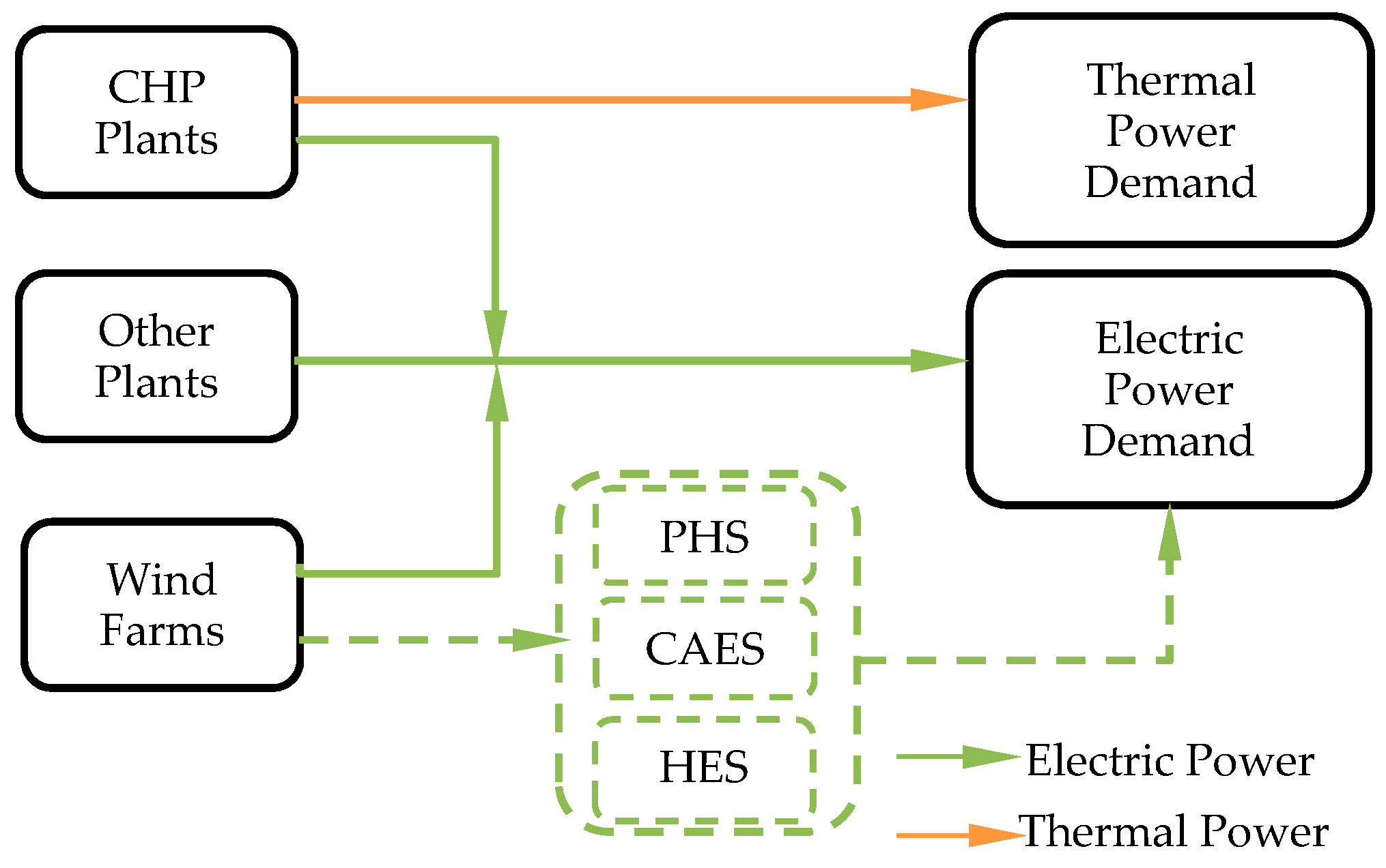
Figure 2 shows a simplified model of the cogeneration system with electric energy storages, which takes the PHS, CAES, and HES as the candidates. From this figure, the electric power is generated by the CHP plants, wind farms, and other plants, and the thermal power demand is supported by the CHP plants. In the following, the basic principles of applying the PHS, CAES, and HES for the wind power integration are presented in brief.
For the PHS, its working philosophy is to let the wind energy be stored in the form of water’s gravitational potential energy, and this stored energy can be reused by the control of hydroelectric turbines. Regarding the CAES, the operation principle is that the wind power drives the compressor to pump the air into an underground cavern, and the compressed air usually mixes with natural gas to produce the electric power by use of the gas turbines. Concerning the HES, its application mechanism is that the wind power activates water electrolysis to generate hydrogen, and the hydrogen is commonly used for the regenerative fuel cell to produce the electric power. On the whole, the suggested three kinds of electric energy storages offer similar theoretical influence on the cogeneration system: consuming surplus wind power during the off-peak periods and transforming the stored energy into electricity during the peak-load periods. On one hand, the electric power and thermal power demands are satisfied simultaneously. On the other hand, the electric power from the CHP units can be reduced, and it is helpful to save the coal cost and the CO2 emission cost. During a scheduling period, it is assumed that the increased wind power consumption is expressed as , the economic benefit created by the electric energy storage is formulated as:
where is the cost of the standard coal, $/ton; is the CO2 emission cost, $/ton; is the coefficient of CO2 emission of standard coal; is the approximate amount of the standard coal required for electric power production, kg/MWh; is the energy efficiency, %; ; is the time interval, in hours.
The employment of electric energy storage increases the cost of the system, including investment cost and maintenance cost. In consideration of the differences in lifetime of the storages, the total cost is amortized into each day during the lifetime periods:
where is the energy capacity and the power capacity is assumed to be ideal; is the life time of the storage, year; r is the bank lending rate, %; D is the running days per year, day. The maintenance cost is usually expressed as a percentage of the investment cost [30], and the percentage is denoted as “the maintenance cost ratio”, , in the present work.
In light of Equations (5) and (6), the comprehensive benefit caused by introducing the electric energy storages is expressed as:
From Equation (7), is a linear function of .
2.3.2. Thermal Energy Auxiliaries
Figure 3 shows simplified model of the cogeneration system with thermal energy auxiliaries, which uses the HS, EB, and HP for the candidates. In practice, the HS, EB, and HP can be installed at the supply side or the demand side. Installing the equipment at the supply-side is convenient for the operators to make the centralized scheduling plan. The distribution of the equipment at the demand-side is helpful for avoiding the transmission losses in the district heating network, but it may increase the cost in the demand-side management (DSM). In light of the current technological level of DSM in the heating network, the HS, EB, and HP are more favorable to be installed at the supply-side in Northern China. In this study, the comparison is conducted in the case of that all the equipment are installed at the supply-side, and the effect of the transmission losses on the comprehensive benefit which will be discussed in our further research is out the scope of the present work.
In the cogeneration system, the function of the HS is to control the store and release of the thermal power at different time ranges. During a scheduling period, the HS is charged on daytimes by extra thermal power from the CHPs under the premise of abundant heat supply. During the off-peak periods at which the wind power curtailment is prone to occur, a part of the heating supply will be served by the HS, and it can decouple the bundling generation of the thermal power and the electric power of the CHP units. Furthermore, it is available to consume more wind power by reducing the electric power output of the CHP units. During a scheduling period, the increased wind power consumption caused by the HS is expressed as , and the thermal power output from the HS is given by:
In fact, because of the energy loss of the HS, the total thermal power generated by the CHP units increases slightly during a scheduling period. Thus, in respect to the reduction of the coal consumption and the CO2 emission, the variation of the CHP units’ thermal power and electric power should be taken into account. Accordingly, the economic benefit is indicated as:
where is the energy efficiency of the HS, %; and is the approximate amount of the standard coal required for thermal power production, kg/MWh.
Since the utilization of the HS also introduces an extra cost, the amortized investment cost of the HS is described as:
where is the energy capacity of the HS and the power capacity is assumed to be ideal.
Based on Equations (9) and (10), the comprehensive benefit of the HS can be expressed as a linear function of as follows:
Being different from the HS, both of the EB and HP have the ability of producing thermal power independently by consuming electric power. In principle, it is not cost-effective to produce the low-grade thermal power by the high-grade electric power. Therefore, it is improper to use the electric power from the CHP units to produce thermal power, and the EB or the HP (EB/HP) is just activated by the wind power which, otherwise, will be wasted when excess wind power generation occurs.
Note that wind power integration is mainly affected by the following two factors: (i) along with the reduction of the electric power from the CHP units, more wind energy can be injected into the power grid; and (ii) since the EB/HP can produce thermal power by consuming electric power, promoting wind power consumption is achieved. If the increased wind power consumption is , the reduction of electric power output of the CHP units should be:
where is the power capacity of the EB/HP and is the unemployed capacity of the EB/HP at time t; .
The saved heat production, , of the CHP units equals to the thermal power supplied by the EB/HP. Substituting Equation (12) into Equation (3), can be formulated as:
Based on Equation (13), the electric power consumed by the EB/HP is expressed as:
In order to avoid the redundant configuration of the EB/HP, the power capacity is supposed to be optimized when the increased consumption of surplus wind power is . The power capacity is derived from the linear optimization function as follows:
The electric power and thermal power of the CHP units are reduced at the same time, contributing to the cost-cutting of the coal fuel and the CO2 emission. The comprehensive benefit of the EB/HP is expressed as:
Based on the aforementioned analysis, the comprehensive benefits caused by different additional equipment are closely associated with the summation of the increased wind power integration during the scheduling period. Thus, the forecast error of the wind power has little effect on the formulation of the comprehensive benefit. Considering the mathematical relationship between the comprehensive benefit and the increased wind power consumption, specific case studies are carried out in the following section, and it is expected to provide a systematic comparison of the electric energy storages and the thermal energy auxiliaries.
3. Case Studies
3.1. Data and System Configuration
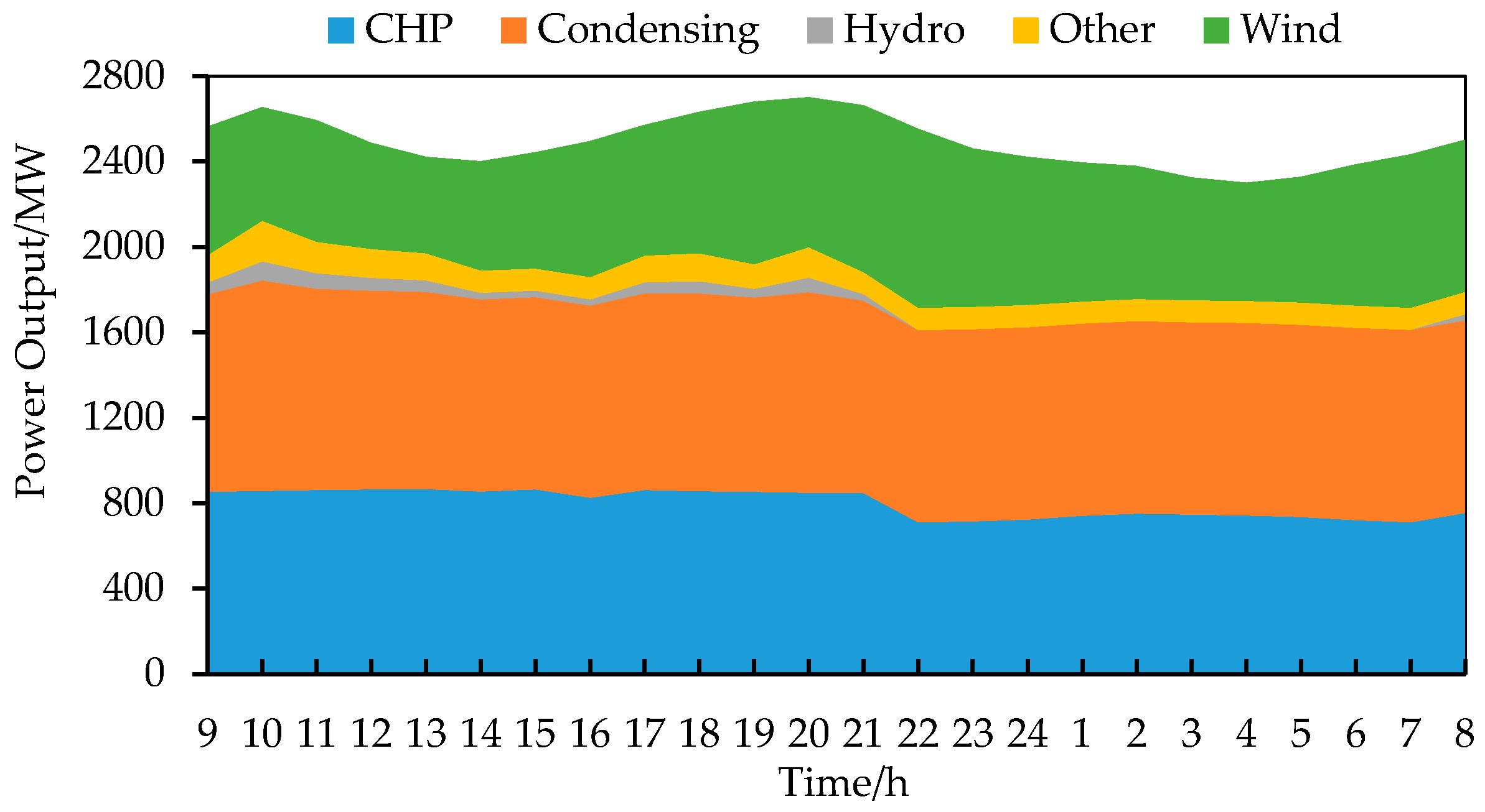
During the case studies, a simplified cogeneration system referring to the power system of WIM is built. The installed capacity of the CHP units is 1000 MW, contributed by two 300 MW CHP units (C240/N300-16.7/538/0.4, Harbin Turbine Co. Ltd., Harbin, Heilongjiang Province, China) and two 200 MW CHP units (C140/N200-12.75/1.08/0.245, Harbin Turbine Co. Ltd., Harbin, Heilongjiang Province, China). The capacities of the conventional condensing units and the hydropower units are 1800 MW and 90 MW, respectively. The total capacity of other types of units is set as 260 MW.
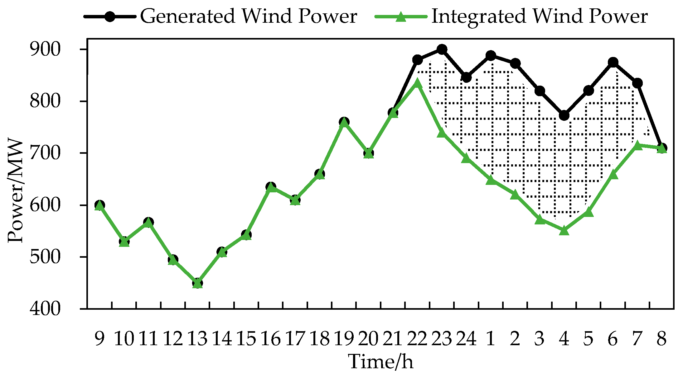
A typical day in the winter is chosen to support the details of the research, that is, the scheduling period is 24 h and is 1 h. The range of the electric power demand is about 2300 MW–2700 MW, and the range of the thermal power demand is about 910 MW–1100 MW. It is assumed that the thermal power demand is completely dependent on the CHP units without additional equipment. The maximum output of the wind power is 900 MW. The electric power outputs of all kinds of units are shown in Figure 4. The generated wind power and integrated wind power are distinguished by curves with different colors in Figure 5. The shadow indicates that the curtailment of wind power occurs from 22:00 p.m. to the next day 7:00 a.m. The total amount of surplus wind power is about 1884 MWh. The parameters of the six candidates are listed in Table 1 and other necessary data are listed in Table 2.
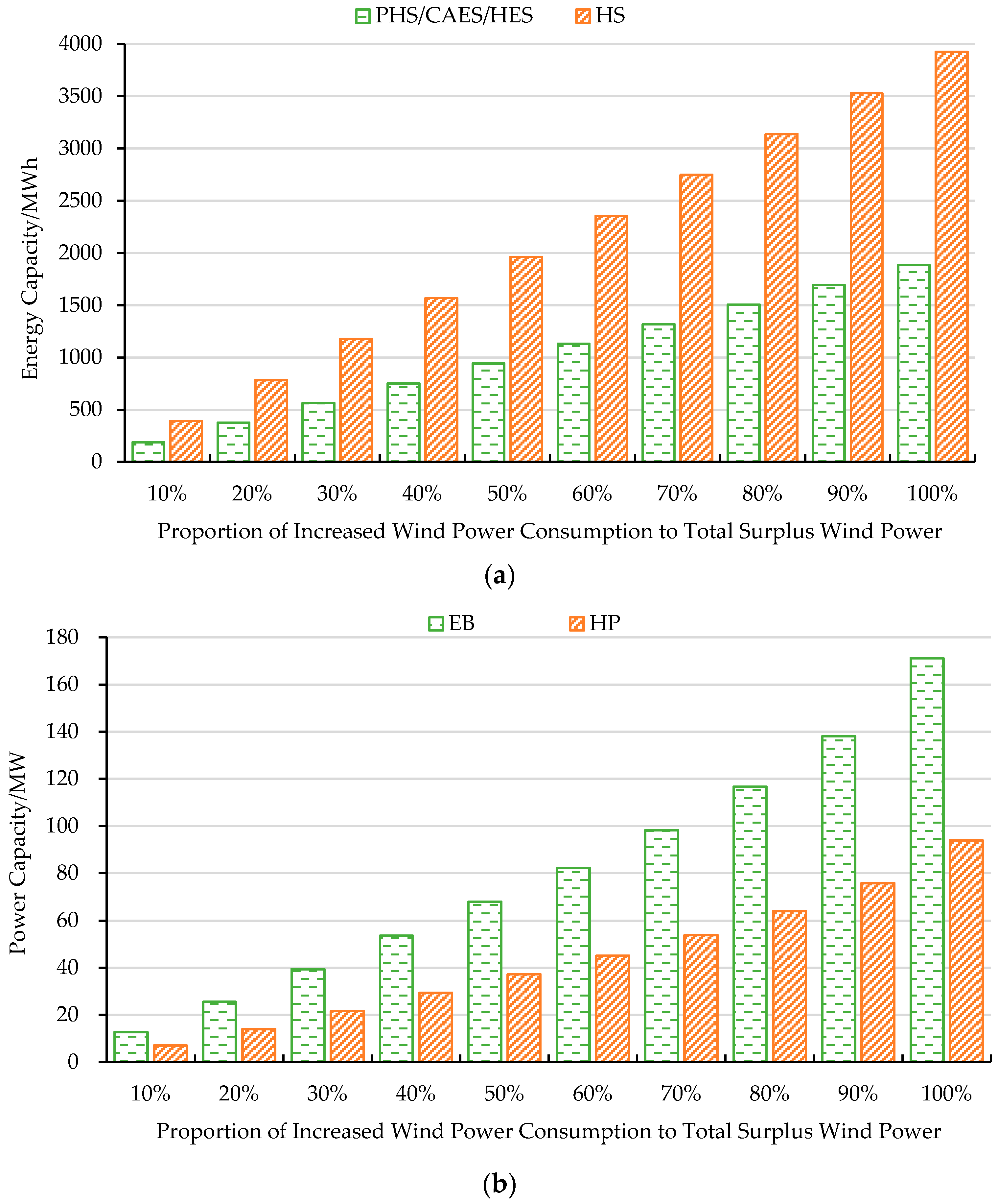
3.2. Comparison of the Six Candidates with Varying Integrated Wind Power
The generation of wind power is different for each day, and that will affect the result of the comprehensive benefit. In view of that the comprehensive benefit is expressed as a function that depends on the summation of the increased wind power integration, this subsection carries out the analysis with different amounts of the consumed wind power. The increased consumption of wind power is set from 10% to 100% of the total surplus wind power (1884 MWh), and the required capacities of electric energy storages and thermal energy auxiliaries change along with the variation of wind power integration, as shown in Figure 6. In addition, the energy capacities of the PHS, CAES, and HES are assumed to be the same according to Equation (6), thus, the capacity variation is depicted by the same green bar in Figure 6a.
The capacity of each equipment keeps growing regularly with the increase of wind power integration. For the energy capacity, the required capacity of the HS is much larger than that of other electric energy storages. For the power capacity, the required capacity of the HP is significantly smaller than that of the EB.
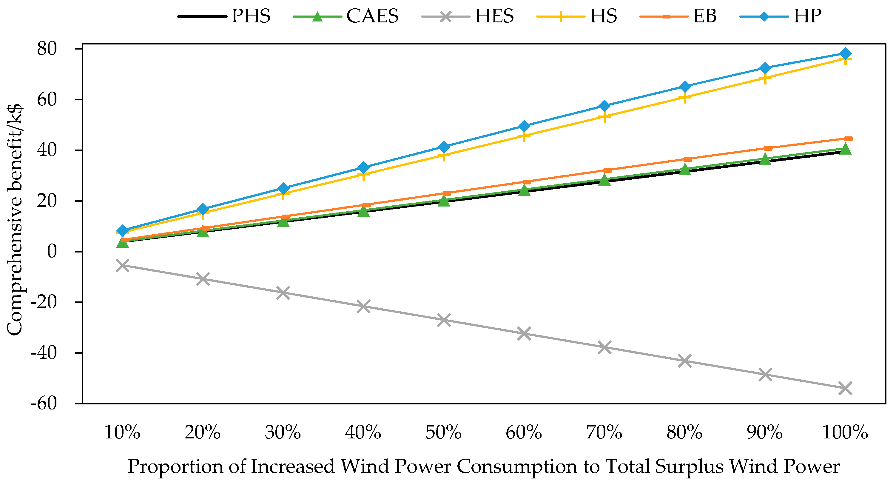
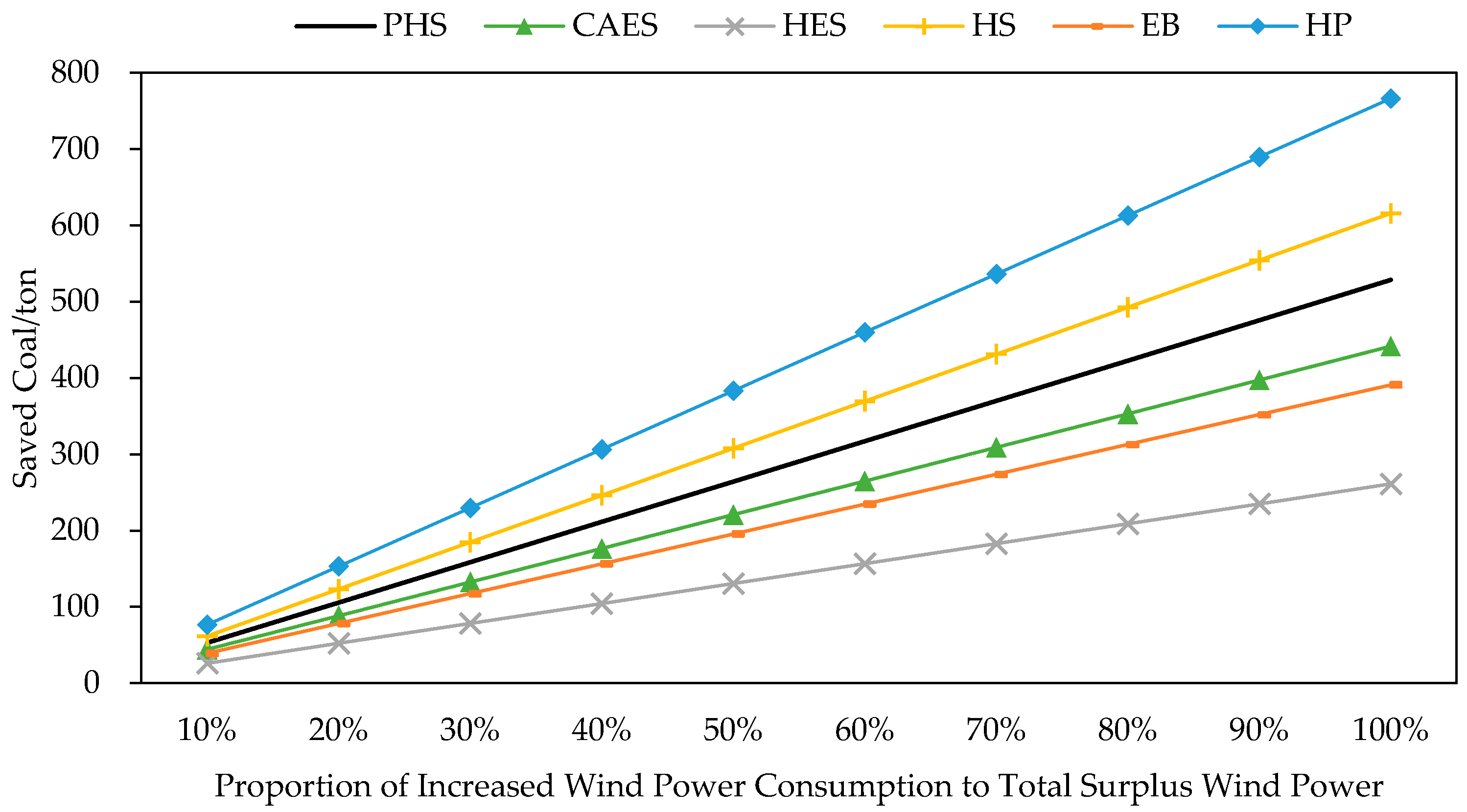
As can be seen from Figure 7, there is an approximate linear correlation between variations of the comprehensive benefit and wind power integration. Due to the superior energy efficiency of the HP, the comprehensive benefit of the HP is the top one. In spite of the large capacity, the comprehensive benefit of the HS is better than the other equipment except for the HP. This is because the investment cost of the HS is very low and. moreover, the saved coal caused by the HS is also considerable, as shown in Figure 8, contributing to a remarkable reduction of fuel cost and CO2 emission cost. The differences of the comprehensive benefits among the PHS, CAES, and the EB are not obvious. The saved coal caused by the PHS is a little better than the CAES and the EB, owing to its slight superiority of energy efficiency. Being different from the others, the HES shows poor performance on the comprehensive benefit. The effect on coal saving of the HES is the worst since the combination of an electrolyzer (energy efficiency 70%) and a fuel cell (energy efficiency 60%) brings on a lower coupled efficiency (approximately 42%). Such low energy efficiency and the considerable investment cost of the HES are collectively responsible for the negative comprehensive benefit.
Note that this study focuses on the performance comparison of the six candidates in daily scheduling and, regarding the capacity optimization of the six candidates in a longer time scale, such as one year or more, details will be conducted in our following-up tasks. Moreover, in consideration of the possible deviation caused by the inaccuracy of several data, further discussion is necessary.
3.3. Further Discussion
The performance of each equipment is greatly affected by the characteristic parameters, especially energy efficiency and unit equipment cost. Table 3 lists the variation range of each equipment’s energy efficiency, and the unit equipment costs are set to change from −20% to +20% of the initial unit cost set in Table 1. The total amount of the consumed wind power is set to be a constant value of 1884 MWh.
Figure 9 shows the comprehensive benefit of the six alternatives with variable energy efficiencies and unit equipment costs. Each color of the line indicates a level of the energy efficiency. The black axes of each radar map represent the settings of the unit equipment cost, namely, the left side of the radar map represents the increased percentages of the unit equipment cost while the right side represents the reduction. The blue wireframes represent the best comprehensive benefit under the highest energy efficiency, and the values are marked at the corner points.
Obviously, each radar map inclines to the right side without crossed lines. This is because the comprehensive benefit is proportional to the energy efficiency and, meanwhile, there is an inverse proportion to the unit equipment cost. The best comprehensive benefit of the HP, namely 82.69 k$, is better than that of other equipment. However, when the unit equipment costs of the HP and the HS both increase by 20%, the best comprehensive benefit of the HS (75.31 k$) is better than that of the HP (73.98 k$). The HES still shows poor performance even if the energy efficiency increases to 60%.
According to the above results, the approximate linear relationship between the comprehensive benefit and the increased amount of wind power integration is verified. Thus, the comparison results of the comprehensive benefit determined by the six alternatives are still convictive when the production of wind power varies in different days. Furthermore, in view of the best comprehensive benefit derived under the specific parameter setting which is achievable in practice, the six alternatives are sorted in descending order as: HP > HS > EB > CAES > PHS > HES.
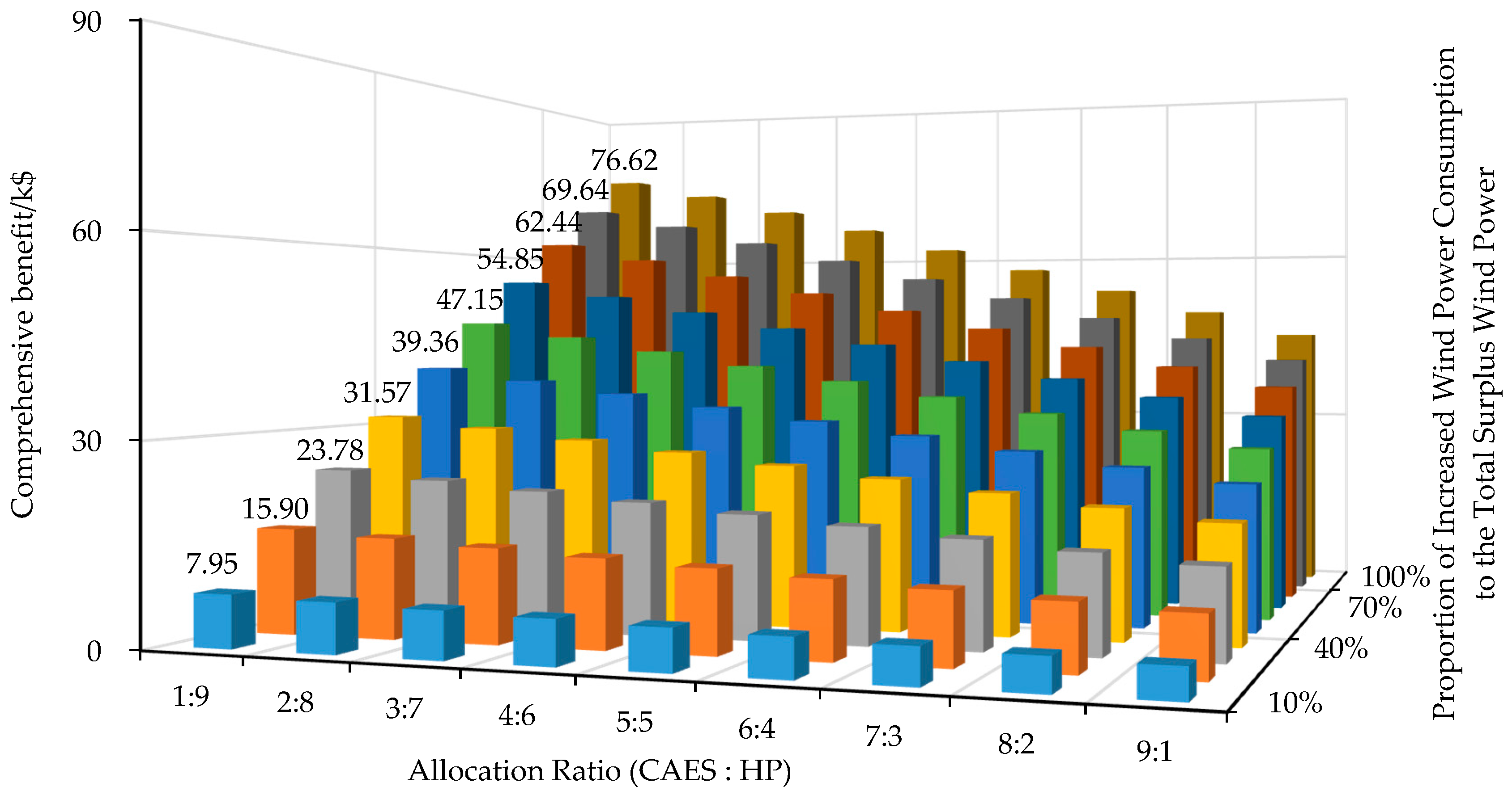
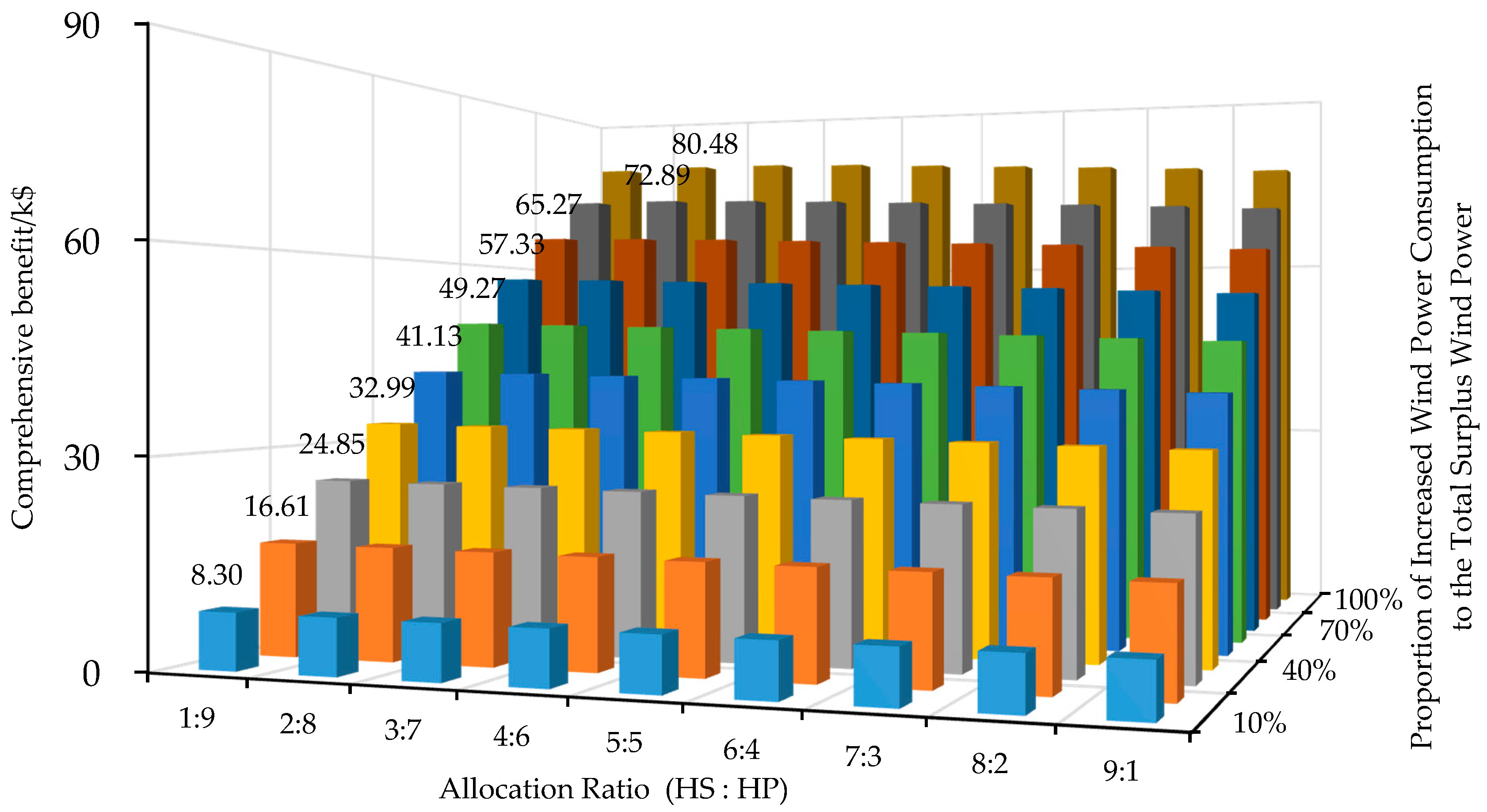
In addition, the combination of different facilities is likely to further promote the comprehensive benefit. Electric energy storage, the CAES, and thermal energy storage, the HS, are chosen to cooperate with the HP, denoting as “CAES&HP” and “HS&HP”, respectively. Figure 10 shows the joint benefits of “CAES&HP” with the varying allocation ratio of the CAES to the HP under different proportions of the increased wind power consumption to the total surplus wind power, and Figure 11 shows the joint benefits of “HS&HP”. The allocation ratio represents the percentage of wind power consumed by one of the equipment. For example, if the allocation ratio of “CAES:HP” is “1:9”, it means that the CAES contributes to 10% of the increased amount of the integrated wind power while the HP takes up 90%.
The best joint benefits are marked out in the figures and listed with the comprehensive benefit of the HP in Table 4. Since the comprehensive benefit of the HP are much better than the CAES, the joint benefits of the “CAES&HP” decrease significantly along with the proportion reduction of the HP, as shown in Figure 10. As displayed in Figure 11, the joint benefits of the “HS&HP” are affected little by the varied allocation ratio, owing to the similar variation curves of the HS’s and HP’s comprehensive benefit. As can be seen from Table 4, the comprehensive benefit of the HP is greater than that of the “CAES&HP” in each case. Only the joint benefits of the “HS&HP” in bold are slightly larger than the comprehensive benefit of the HP when the increased wind power consumption reaches up to 80%, 90%, and 100% of the total surplus wind power. Correspondingly, the allocation ratios of the HS to the HP are 1:9, 2:8 and 2:8. The results suggest that in order to get the best benefit, the allocation of the equipment should be optimized according to the requirement of wind power accommodation in practice.
4. Conclusions
In order to promote wind power integration, this paper conducts the utilization of different electric energy storages and thermal energy auxiliaries, and performs a systematic comparison of HP, HS, EB, CAES, PHS, and HES. According to the operation characteristic of the CHP units, a WTCE is proposed to define the contradiction between the heat supply and the wind power utilization and, further, an efficient approach is put forward to calculate the required capacities of the HP, HS, EB, CAES, PHS, and HES. In terms of construction investment, coal saving, and CO2 emission reduction, an evaluation function of the comprehensive benefit is suggested. Finally, based on the numerical studies, the performance verification is done, and the following results are obtained:
(1) There is an approximate linear relationship between the comprehensive benefit and the amount of integrated wind power. The comprehensive benefit is affected by the summation of wind power consumption during a dispatching cycle instead of the amount of wind power consumed at each time interval. This makes the formulation method of the comprehensive benefit applicable for different wind production scenarios.
(2) The HP offers the best comprehensive benefit for the cogeneration system. The HS is low-cost, but its effects on coal saving is far inferior to the HP. Hence, the comprehensive benefit of the HS is slightly weaker than that of the HP. Compared to the HP and HS, the PHS, CAES, and EB have similar comprehensive benefits and also have no significant differences in coal saving. Owing to the poor energy efficiency, the HES is the worst choice for consuming surplus wind power. As a whole, in view of the integrated performance, the six candidates can be sorted in descending order as: HP > HS > EB > CAES > PHS > HES.
(3) Compared to just the use of the HP, the combined utilization of the HS and the HP is likely to provide better comprehensive benefit for the cogeneration system with very high penetration of wind power. Note that, if the HP cooperates with the device that has very poor comprehensive benefit, the combined benefits of them will be inferior to that of the HP, and this means that this kind of combination is not recommended.
(4) Changing the parameters, especially energy efficiency and unit equipment cost, will affect the specific calculation value of the comprehensive benefit. However, it will not subvert the comparison results in principle, since the parameter settings of the additional equipment in the case studies are practically achievable.
Advanced studies on different combined utilizations of electric energy storages and thermal energy auxiliaries are our following-up tasks. Optimal capacity configuration in consideration of the equipment location will be conducted in the future. Research results will be reported in later articles.
Acknowledgments
This work is supported by the National Natural Science Foundation of China under grant 51507117.
Author Contributions
Yanjuan Yu conducted the simulation model and wrote the manuscript. Hongkun Chen contributed to the frame construction of the manuscript. Lei Chen provided some helpful suggestions to consummate the proposed method. All the authors helped to check and revise the manuscript.
Conflicts of Interest
The authors declare no conflict of interest.
Nomenclature
| Abbreviation | |||
| CHP | Combined heat and power | SMES | Superconducting magnetic energy storage |
| PHS | Pumped hydro storage | HS | Heat storage |
| CAES | Compressed air energy storage | EB | Electric boiler |
| HES | Hydrogen-based energy storage | HP | Heat pump |
| BES | Battery energy storage | WTCE | Wind-thermal conflicting expression |
| FES | Flywheel energy storage | ||
| Index sets | |||
| i | Index set of the CHP units | p | Index set of electric energy storage |
| t | Index set of dispatch time interval | q | Index set of thermal energy auxiliaries |
| Symbols | |||
| Increased amount of wind power integration at time t, MWh | Insufficient amount of heating power supply, MWh | ||
| Electric power reduction of the i-th CHP unit, MWh | Thermal power reduction of the i-th CHP unit, MWh | ||
| Electric power reduction of CHPs, MWh | Thermal power reduction of CHPs, MWh | ||
| Standard coal required for electric power production, kg/MWh | Standard coal required for thermal power production, kg/MWh | ||
| Energy capacity of the electric energy storage, MWh | Unemployed power capacity of the EB/HP, MW | ||
| Energy Capacity of the heat storage, MWh | Power capacity of the EB/HP, MW | ||
| Economic benefit, $ | Energy efficiency, % | ||
| Investment cost, $ | Maintenance cost ratio, % | ||
| Comprehensive benefit, $ | r | Bank lending rate, % | |
| Cost of the standard coal, $/ton | y | Life time, year | |
| Cost of the CO2 emission, $/ton | D | Running days per year, day | |
| CO2 emission coefficient of standard coal | |||
References
- Li, Z.; Wu, W.; Shahidehpour, M.; Wang, J.; Zhang, B. Combined heat and power dispatch considering pipeline energy storage of district heating network. IEEE Trans. Sustain. Energy 2016, 7, 12–22. [Google Scholar] [CrossRef]
- Petchers, N. Combined Heating, Cooling & Power Handbook: Technologies & Applications an Integrated Approach to Energy Resource Optimization; The Fairmont Press Inc.: Lilburn, GA, USA, 2003. [Google Scholar]
- National Energy Administration. 2010 Statistics of Wind Power Development. Available online: http://www.nea.gov.cn/2011-07/05/c_131086514.htm (accessed on 5 July 2011).
- Yao, E.; Wang, H.; Liu, L.; Xi, G. A novel constant-pressure pumped hydro combined with compressed air energy storage system. Energies 2014, 8, 154–171. [Google Scholar] [CrossRef]
- Xiong, M.; Gao, F.; Liu, K.; Chen, S.; Dong, J. Optimal real-time scheduling for hybrid energy storage systems and wind farms based on model predictive control. Energies 2015, 8, 8020–8051. [Google Scholar] [CrossRef]
- Long, H.; Xu, R.; He, J. Incorporating the variability of wind power with electric heat pumps. Energies 2011, 4, 1748–1762. [Google Scholar] [CrossRef]
- Rong, S.; Li, W.; Li, Z.; Sun, Y.; Zheng, T. Optimal allocation of thermal-electric decoupling systems based on the national economy by an improved conjugate gradient method. Energies 2016, 9, 17. [Google Scholar] [CrossRef]
- Hozouti, M.A.; Abbaspour, A.; Fotuhi-Firuzabad, M.; Moeini-Aghtaie, M. On the use of pumped storage for wind energy maximization in transmission-constrained power systems. IEEE Trans. Power Syst. 2015, 30, 1017–1025. [Google Scholar] [CrossRef]
- Helseth, A.; Gjelsvik, A.; Mo, B.; Ulfar, L. A model for optimal scheduling of hydro thermal systems including pumped-storage and wind power. IET Gener. Transm. Distrib. 2013, 7, 1426–1434. [Google Scholar] [CrossRef]
- Sousa, J.A.; Teixeira, F.; Faias, S. Impact of a price-maker pumped storage hydro unit on the integration of wind energy in power systems. Energy 2014, 69, 3–11. [Google Scholar] [CrossRef]
- Li, H.; Zheng, C.; Lv, S.; Liu, S.; Huo, C. Research on optimal capacity of wind power based on coordination with pumped storage power. In Proceedings of the 2016 IEEE PES Asia-Pacific Power and Energy Engineering Conference (APPEEC), Xi’an, China, 25–28 October 2016; pp. 1214–1218. [Google Scholar]
- Zhang, N.; Kang, C.; Kirschen, D.S.; Xia, Q.; Xi, W.; Huang, J.; Zhang, Q. Planning pumped storage capacity for wind power integration. IEEE Trans. Sustain. Energy 2013, 4, 393–401. [Google Scholar] [CrossRef]
- Gu, Y.; McCalley, J.; Ni, M.; Bo, R. Economic modeling of compressed air energy storage. Energies 2013, 6, 2221–2241. [Google Scholar] [CrossRef]
- Cleary, B.; Duffy, A.; OConnor, A.; Conlon, M.; Fthenakis, V. Assessing the economic benefits of compressed air energy storage for mitigating wind curtailment. IEEE Trans. Sustain. Energy 2015, 6, 1021–1028. [Google Scholar] [CrossRef]
- Li, N.; Hedman, K.W. Economic assessment of energy storage in systems with high levels of renewable resources. IEEE Trans. Sustain. Energy 2015, 6, 1103–1111. [Google Scholar] [CrossRef]
- Schiebahn, S.; Grube, T.; Robinius, M.; Tietze, V.; Kumar, B.; Stolten, D. Power to gas: Technological overview, systems analysis and economic assessment for a case study in Germany. Int. J. Hydrogen Energy 2015, 40, 4285–4294. [Google Scholar] [CrossRef]
- Ancona, M.A.; Antonioni, G.; Branchini, L.; De Pascale, A.; Melino, F.; Orlandini, V.; Ferraro, M. Renewable energy storage system based on a Power-to-Gas conversion process. Energy Procedia 2016, 101, 854–861. [Google Scholar] [CrossRef]
- Yuan, R.; Ye, J.; Lei, J.; Li, T. Integrated combined heat and power system dispatch considering electrical and thermal energy storage. Energies 2016, 9, 474. [Google Scholar] [CrossRef]
- Melo, D.F.R.; Chang-Chien, L.R. Synergistic control between hydrogen storage system and offshore wind farm for grid operation. IEEE Trans. Sustain. Energy 2014, 5, 18–27. [Google Scholar] [CrossRef]
- Trifkovic, M.; Sheikhzadeh, M.; Nigim, K.; Daoutidis, P. Modeling and control of a renewable hybrid energy system with hydrogen storage. IEEE Tran. Contr. Syst. Technol. 2014, 22, 169–179. [Google Scholar] [CrossRef]
- Jannati, M.; Hosseinian, S.H.; Vahidi, B. A significant reduction in the costs of battery energy storage systems by use of smart parking lots in the power fluctuation smoothing process of the wind farms. Renew. Energy 2016, 87, 1–14. [Google Scholar] [CrossRef]
- Abdeltawab, H.H.; Mohamed, Y.A.R.I. Robust energy management of a hybrid wind and flywheel energy storage system considering flywheel power losses minimization and grid-code constraints. IEEE Trans. Ind. Electron. 2016, 63, 4242–4254. [Google Scholar] [CrossRef]
- Zhang, N.; Gu, W.; Yu, H.; Liu, W. Application of coordinated SOFC and SMES robust control for stabilizing tie-line power. Energies 2013, 6, 1902–1917. [Google Scholar] [CrossRef]
- Hossain, J.; Sakib, N.; Hossain, E.; Bayindir, R. Modelling and simulation of solar plant and storage system: A step to microgrid technology. Int. J. Renew. Energy Res. 2017, 7, 723–737. [Google Scholar]
- Rinne, S.; Syri, S. The possibilities of combined heat and power production balancing large amounts of wind power in Finland. Energy 2015, 82, 1034–1046. [Google Scholar] [CrossRef]
- Nielsen, M.G.; Morales, J.M.; Zugno, M.; Pedersen, T.E.; Madsen, H. Economic valuation of heat pumps and electric boilers in the Danish energy system. Appl. Energy 2016, 167, 189–200. [Google Scholar] [CrossRef]
- Hedegaard, K.; Mathiesen, B.V.; Lund, H.; Heiselberg, P. Wind power integration using individual heat pumps–analysis of different heat storage options. Energy 2012, 47, 284–293. [Google Scholar] [CrossRef]
- Nuytten, T.; Claessens, B.; Paredis, K.; Van Bael, J.; Six, D. Flexibility of a combined heat and power system with thermal energy storage for district heating. Appl. Energy 2013, 104, 583–591. [Google Scholar] [CrossRef]
- Yu, Y.J.; Chen, H.K.; Jiang, X.; Tao, Y.B.; Yu, R.Y. Operation strategy for heat storage tank to improve wind power integration. Autom. Electr. Power Syst. 2017, 41, 37–43. [Google Scholar]
- Liu, D.; Zhang, G.; Huang, B.; Liu, W. Optimum electric boiler capacity configuration in a regional power grid for a wind power accommodation scenario. Energies 2016, 9, 144. [Google Scholar] [CrossRef]
- Zidan, A.; Gabbar, H.A. DG mix and energy storage units for optimal planning of self-sufficient micro energy grids. Energies 2016, 9, 616. [Google Scholar] [CrossRef]
- Petrović, S.N.; Karlsson, K.B. Residential heat pumps in the future Danish energy system. Energy 2016, 114, 787–797. [Google Scholar] [CrossRef]
- Cooper, S.J.G.; Hammond, G.P.; McManus, M.C.; Pudjianto, D. Detailed simulation of electrical demands due to nationwide adoption of heat pumps, taking account of renewable generation and mitigation. IET Renew. Power Gener. 2016, 10, 380–387. [Google Scholar] [CrossRef] [Green Version]
- Chen, X.; Kang, C.; O’Malley, M.; Xia, Q.; Bai, J.; Liu, C.; Li, H. Increasing the flexibility of combined heat and power for wind power integration in China: Modeling and implications. IEEE Trans. Power Syst. 2015, 30, 1848–1857. [Google Scholar] [CrossRef]
- Rong, S.; Li, Z.; Li, W. Investigation of the promotion of wind power consumption using the thermal-electric decoupling techniques. Energies 2015, 8, 8613–8629. [Google Scholar] [CrossRef]
- Wu, C.; Gu, W.; Jiang, P.; Li, Z.; Cai, H.; Li, B. Combined economic dispatch considering the time-delay of a district heating network and multi-regional indoor temperature control. IEEE Trans. Sustain. Energy 2018, 9, 118–127. [Google Scholar] [CrossRef]
- Smallbone, A.; Jülch, V.; Wardle, R.; Roskilly, A.P. Levelised cost of storage for pumped heat energy storage in comparison with other energy storage technologies. Energy Conver. Manag. 2017, 152, 221–228. [Google Scholar] [CrossRef]
- Comodi, G.; Carducci, F.; Sze, J.Y.; Balamurugan, N.; Romagnoli, A. Storing energy for cooling demand management in tropical climates: A techno-economic comparison between different energy storage technologies. Energy 2017, 121, 676–694. [Google Scholar] [CrossRef]
- Hayes, B.P.; Wilson, A.; Webster, R.; Djokic, S.Z. Comparison of two energy storage options for optimum balancing of wind farm power outputs. IET Gener. Transm. Distrib. 2016, 10, 832–839. [Google Scholar] [CrossRef]
- Blarke, M.B. Towards an intermittency-friendly energy system: Comparing electric boilers and heat pumps in distributed cogeneration. Appl. Energy 2012, 91, 349–365. [Google Scholar] [CrossRef]
- Chen, X.; Lu, X.; McElroy, M.B.; Nielsen, C.P.; Kang, C. Synergies of wind power and electrified space heating: Case study for Beijing. Environ. Sci. Technol. 2014, 48, 2016–2024. [Google Scholar] [CrossRef] [PubMed]
- Rinne, S.; Syri, S. Heat pumps versus combined heat and power production as CO2 reduction measures in Finland. Energy 2013, 57, 308–318. [Google Scholar] [CrossRef]
- Lund, P.D.; Lindgren, J.; Mikkola, J.; Salpakari, J. Review of energy system flexibility measures to enable high levels of variable renewable electricity. Renew. Sustain. Energy Rev. 2015, 45, 785–807. [Google Scholar] [CrossRef]
- Mathiesen, B.V.; Lund, H. Comparative analyses of seven technologies to facilitate the integration of fluctuating renewable energy sources. IET Renew. Power Gener. 2009, 3, 190–204. [Google Scholar] [CrossRef]
- Lu, C.; Xu, H.; Pan, X.; Song, J. Optimal sizing and control of battery energy storage system for peak load shaving. Energies 2014, 7, 8396–8410. [Google Scholar] [CrossRef]
- Christidis, A.; Koch, C.; Pottel, L.; Tsatsaronis, G. The contribution of heat storage to the profitable operation of combined heat and power plants in liberalized electricity markets. Energy 2012, 41, 75–82. [Google Scholar] [CrossRef]
- Li, P.; Wang, H.; Lv, Q.; Li, W. Combined heat and power dispatch considering heat storage of both buildings and pipelines in district heating system for wind power integration. Energies 2017, 10, 893. [Google Scholar] [CrossRef]
- Nielsen, M.G. Probabilistic Forecasting and Optimization in CHP Systems. Master’s Thesis, Technical University of Denmark, Lyngby, Denmark, 2017. [Google Scholar]
- Evans, A.; Strezov, V.; Evans, T.J. Assessment of utility energy storage options for increased renewable energy penetration. Renew. Sustain. Energy Rev. 2012, 16, 4141–4147. [Google Scholar] [CrossRef]
- Díaz-González, F.; Sumper, A.; Gomis-Bellmunt, O.; Villafáfila-Robles, R. A review of energy storage technologies for wind power applications. Renew. Sustain. Energy Rev. 2012, 16, 2154–2171. [Google Scholar] [CrossRef]
- Zakeri, B.; Syri, S. Electrical energy storage systems: A comparative life cycle cost analysis. Renew. Sustain. Energy Rev. 2015, 42, 569–596. [Google Scholar] [CrossRef]
- Lv, Q.; Li, L.; Zhu, Q.S.; Wang, H.X.; Liu, R.; Li, W.D. Comparison of coal-saving effect and national economic indices of three feasible curtailed wind power accommodating strategies. Autom. Electr. Power Syst. 2015, 39, 75–83. [Google Scholar]
Figure 1.
Operation regions of the combined heat and power (CHP) units: (a) back-pressure unit; and (b) the extraction-condensing unit. The thermal power and electric power are denoted as Q and P, respectively. A, B, C, and D are the extreme points.
Figure 1.
Operation regions of the combined heat and power (CHP) units: (a) back-pressure unit; and (b) the extraction-condensing unit. The thermal power and electric power are denoted as Q and P, respectively. A, B, C, and D are the extreme points.

Figure 2.
Simplified model of the cogeneration system with electric energy storages. PHS: pumped hydro storage; CAES: compressed air energy storage; HES: hydrogen-based energy storage.
Figure 2.
Simplified model of the cogeneration system with electric energy storages. PHS: pumped hydro storage; CAES: compressed air energy storage; HES: hydrogen-based energy storage.

Figure 3.
Simplified model of the cogeneration system with thermal energy auxiliaries. HS: heat storage; EB: electric boilers; HP: heat pumps.
Figure 3.
Simplified model of the cogeneration system with thermal energy auxiliaries. HS: heat storage; EB: electric boilers; HP: heat pumps.
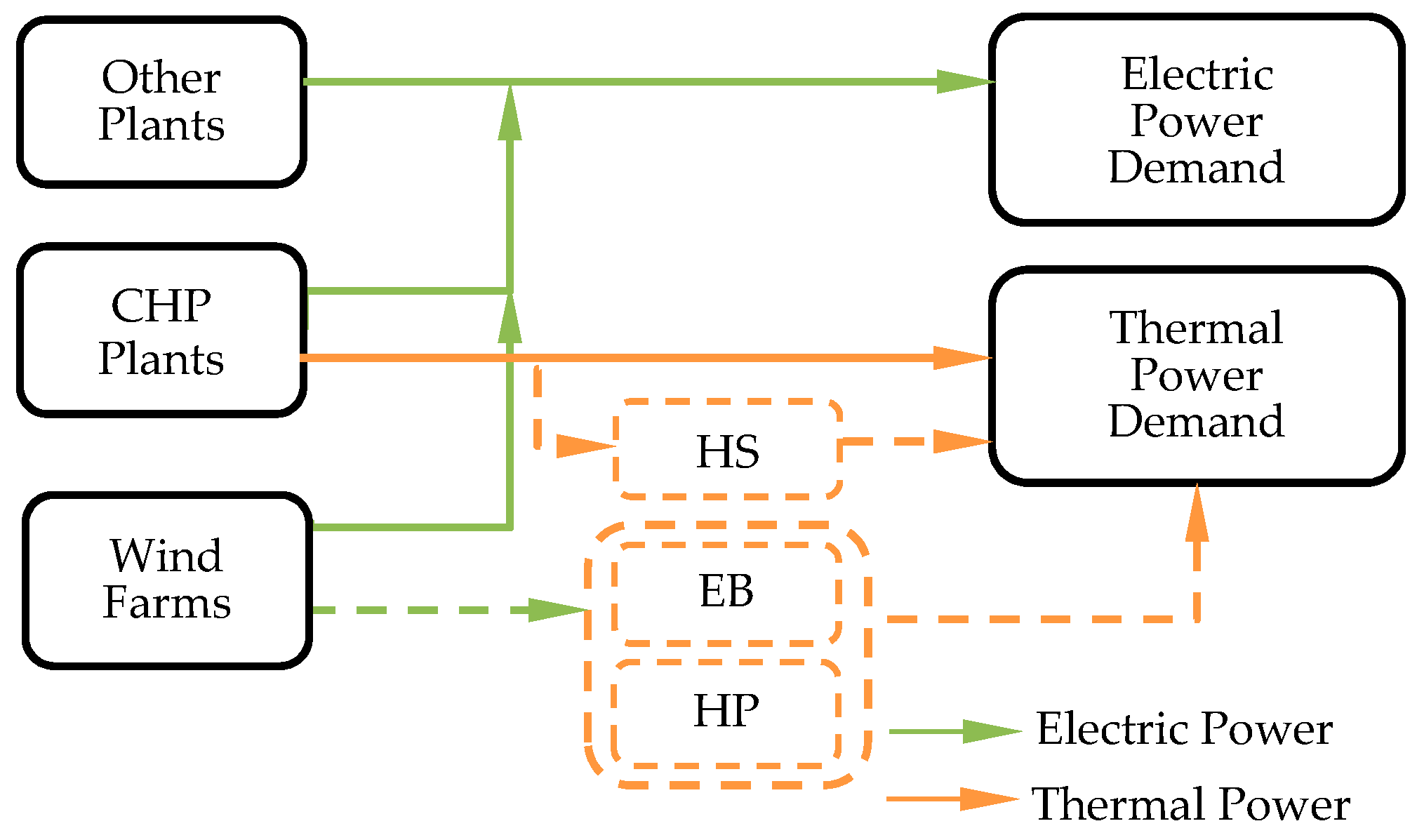
Figure 4.
Electric power outputs of the units.

Figure 5.
Curves of generated wind power and integrated wind power.

Figure 6.
Capacity variation of the six candidates: (a) energy capacities of electric energy storage and the HS; and (b) power capacities of the EB and the HP.
Figure 6.
Capacity variation of the six candidates: (a) energy capacities of electric energy storage and the HS; and (b) power capacities of the EB and the HP.

Figure 7.
Comprehensive benefit of different equipment with varying consumption of wind power.

Figure 8.
Comparison of saved coal of different equipment with varying consumption of wind power.

Figure 9.
Comprehensive benefit of the six alternatives with variable energy efficiencies and unit equipment costs: (a) PHS; (b) CAES; (c) HES; (d) HS; (e) EB; and (f) HP.
Figure 9.
Comprehensive benefit of the six alternatives with variable energy efficiencies and unit equipment costs: (a) PHS; (b) CAES; (c) HES; (d) HS; (e) EB; and (f) HP.
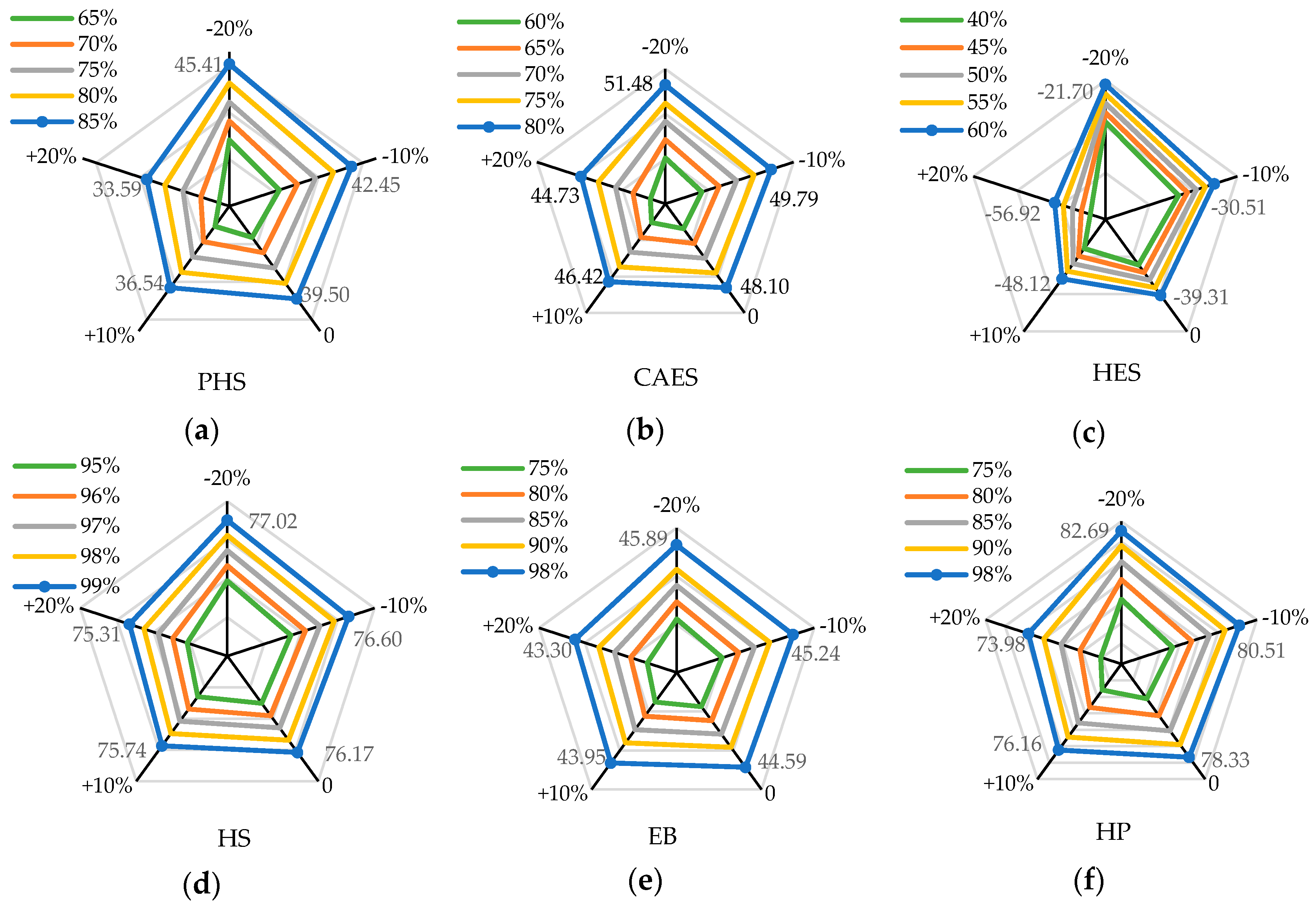
Figure 10.
The joint benefits of the CAES and the HP with varying allocation ratio of the CAES to the HP under each proportion of the increased wind power consumption to the total surplus wind power.
Figure 10.
The joint benefits of the CAES and the HP with varying allocation ratio of the CAES to the HP under each proportion of the increased wind power consumption to the total surplus wind power.

Figure 11.
The joint benefits of the HS and the HP with varying allocation ratio of the HS to the HP under each proportion of the increased wind power consumption to the total surplus wind power.
Figure 11.
The joint benefits of the HS and the HP with varying allocation ratio of the HS to the HP under each proportion of the increased wind power consumption to the total surplus wind power.


Table 1.
Parameters of the six alternatives.
| Parameters | PHS | CAES | HES | HS | EB | HP |
|---|---|---|---|---|---|---|
| Energy Efficiency | 85% | 71% | 42% | 99% | 98% | 3.5 (COP) 1 |
| Life Time | 50 years | 40 years | 15 years | 50 years | 20 years | 20 years |
| Maintenance Cost Ratio 2 | 0.9% | 0.46% | 1% | 0.5% | 0.5% | 1% |
| Unit Cost | 79 $/kWh | 46 $/kWh | 151 $/kWh | 5.8 $/kWh | 150 $/kW | 870 $/kW |
| References | [49,50,51] | [49,50,51] | [50,51] | [25,52] | [44,52] | [25,30,44] |
1 COP is the abbreviation of coefficient of performance, and it is the ratio of the consumed electric power to the produced thermal power of the HP. 2 Maintenance cost ratio is the proportion of the total investment cost.
Table 2.
Other necessary data.
| Items | Ccoal | Ccarbon | α | Pcoal | Qcoal | r | D | k_av |
|---|---|---|---|---|---|---|---|---|
| Data | 120 $/ton | 4 $/ton | 2.66 | 330 kg/MWh | 153 kg/MWh | 6% | 365 | 0.48 |
Table 3.
Variation ranges of energy efficiencies.
| Parameters | PHS | CAES | HES | HS | EB | HP |
|---|---|---|---|---|---|---|
| Energy Efficiency | 65–85% | 60–80% | 40–60% | 95–99% | 75–98% | 2.5–3.5 (COP) |
Table 4.
Comparison of the joint benefits and the comprehensive benefit of the HP.
| Proportion 1 | 10% | 20% | 30% | 40% | 50% | 60% | 70% | 80% | 90% | 100% |
|---|---|---|---|---|---|---|---|---|---|---|
| HP Benefit/k$ | 8.38 | 16.76 | 25.02 | 33.22 | 41.42 | 49.61 | 57.58 | 65.24 | 72.54 | 78.33 |
| CAES&HP Benefit/k$ | 7.95 | 15.90 | 23.78 | 31.57 | 39.36 | 47.15 | 54.85 | 62.44 | 69.64 | 76.62 |
| HS&HP Benefit/k$ | 8.30 | 16.61 | 24.85 | 32.99 | 41.13 | 49.27 | 57.33 | 65.27 2 | 72.89 | 80.48 |
1 Proportion of the increased wind power consumption to the total surplus wind power. 2 The values in bold indicate that the joint benefits of the “HS&HP” are larger than the comprehensive benefit of the HP.
© 2018 by the authors. Licensee MDPI, Basel, Switzerland. This article is an open access article distributed under the terms and conditions of the Creative Commons Attribution (CC BY) license (http://creativecommons.org/licenses/by/4.0/).
Share and Cite
MDPI and ACS Style
Yu, Y.; Chen, H.; Chen, L. Comparative Study of Electric Energy Storages and Thermal Energy Auxiliaries for Improving Wind Power Integration in the Cogeneration System. Energies 2018, 11, 263. https://doi.org/10.3390/en11020263
AMA Style
Yu Y, Chen H, Chen L. Comparative Study of Electric Energy Storages and Thermal Energy Auxiliaries for Improving Wind Power Integration in the Cogeneration System. Energies. 2018; 11(2):263. https://doi.org/10.3390/en11020263
Chicago/Turabian StyleYu, Yanjuan, Hongkun Chen, and Lei Chen. 2018. "Comparative Study of Electric Energy Storages and Thermal Energy Auxiliaries for Improving Wind Power Integration in the Cogeneration System" Energies 11, no. 2: 263. https://doi.org/10.3390/en11020263
Note that from the first issue of 2016, this journal uses article numbers instead of page numbers. See further details here.