The Optimization Design of Short-Term High-Overload Permanent Magnet Motors Considering the Nonlinear Saturation

1
Department of Electrical Engineering, Harbin Institute of Technology, Harbin 150001, China
2
Department of Armament Science and Technology, Xi’an High-tech Institution, Xi’an 710025, China
*
Author to whom correspondence should be addressed.
Energies 2018, 11(12), 3272; https://doi.org/10.3390/en11123272
Submission received: 31 October 2018
/
Revised: 19 November 2018
/
Accepted: 22 November 2018
/
Published: 23 November 2018
Abstract
:Electric actuators with fast dynamic response and high torque density are widely used in aerospace and industrial applications. In this paper, the design and optimization of a short-term high-overload permanent magnet synchronous motor (STHO-PMSM) is presented. The rated working point is optimized according to the operating conditions of the motor. The effect of electromagnetic load on the extreme torque which mainly include ampoule number and the magnetic energy of the PM is researched. Due to the nonlinear saturation influence, the equivalent magnetic network model is established. The saturation torque discount factor is proposed to quantify the degree of the core magnetic saturation. Winding temperature model is presented to inspect the motor reliability. To verify the feasibility and accuracy of mathematical model analysis (MMA), the performance of the motor in different currents is investigated compared to the finite element analysis (FEA). A prototype motor is manufactured and tested. The results of the MMA, FEA, and experiment show that the designed motor can achieve the high performance with the 10 times overload in a short time. The method of the MMA can relatively accurately predict as well as take less time consumption.
1. Introduction
With the development of all-electronics technology, electric actuators are widely used in aerospace, industrial applications, etc. The volume and quality of these motors are strictly restricted due to the characteristics of high dynamic response, maximum power-to-weight ratio and high torque-inertia ratio. Alternatively, the performance and lifetime of the motor are affected by the temperature. Permanent magnet synchronous motors are the first choice due to their simple structure, high torque density, and high power density [1,2,3,4,5,6,7]. The high dynamic response performance of the motor also means that the output torque can reach high value compared to rated torque in a short time. Therefore, the short-time high overload capability of the motor is very important for the steering gear and industrial motor [8].
The torque of the short-term high-overload permanent magnet synchronous motor (STHO-PMSM) is lower under rated conditions. However, during the process of frequent acceleration and deceleration, the output torque is high for a short time [9]. Therefore, improving the maximum output power density is an important design goal. The volume and quality of the motor can be optimized under the premise of meeting the performance and reliability requirements [10].
A lot of research on high power density motors has been performed. The effect of rotor structure on the magnetic adjusting performance of an axial-radial permanent magnetic machine was investigated [11]. The design of the PMSM retaining plate with 3-D barrier structure is optimized to reduce the loss compared to the conventional structure [12]. Various optimization methods have also been adopted according to the different driving cycle [13] and mathematical algorithm [14]. To achieve the high torque density and low torque ripple, fractional slot concentrated winding permanent magnet synchronous machines are studied by optimizing rotor structure [15,16]. In terms of multi-phase winding motor, some research work to improve the output torque [17,18] was carried out. Most of the above goals are to improve power density under rated conditions. However, high maximum output power density and the high ultimate torque for a short time are the pursued performance of short-term high-overload motors. It is very important to improve the ultimate torque performance where the key is to increase the electromagnetic load of the motor [19,20]. Excessive electrical load will cause a high temperature rise of the motor in a short time decreasing the reliability of the motor [21,22]. There are many research methods to accurately and rapidly calculate the temperature rise of the motor and improve its reliability [23,24,25,26]. Besides, excessive magnetic load can increase the motor core saturation so that the extreme torque is reduced. Refs. [27,28] studied the calculation of inductance considering magnetic saturation. The air-gap and zigzag leakage fluxes in a mounted permanent-magnet (PM) machine were modeled and analyzed [29,30]. A nonlinear analytical model of the reluctance machine considering the effect of the rotor geometry on average torque and the torque harmonics has been studied [31]. However, there is a lack of research on the influence of magnetic saturation on the extreme torque and is not considered in the design process of the motor.
Optimization by using parametric models is a very effective method in the process of the motor design and optimization [32,33]. But it takes a lot of time to perform finite element analysis of parametric modeling compared to the MMA although the predictive accuracy of the former is slightly better. Therefore, using the MMA method is favorable in the initial stage of motor design and optimization where one needs to quickly produce a relatively accurate and feasible plan. Reference [34] proposes a design process of permanent magnet assisted synchronous reluctance motors by means of coupled magnetic, thermal and electrical models. The optimization process is based on a multi-objective cost function within a torque-speed interval, but is no optimization for how to increase the extreme torque.
In this paper, the operating conditions of the STHO-PMSM are investigated to optimize the rated working point. The influences of electrical load and magnetic load on the extreme torque of the motor are analyzed, respectively, in Section 2, where it is reasonable and necessary to reduce the number of windings per phase to increasing the electrical load and thus to achieve the high-overload multiples extreme torque. In Section 3, the equivalent magnetic network model is established considering the iron core saturation by iterative calculation. The effect of the nonlinear saturation on torque is quantified by the saturation torque discount factor that is the rate of the airgap magnetomotive force (MMF) of load and no-load. In Section 4, the temperature rise of the winding and iron core is computed to verify the reliability of the motor by using lumped parameter thermal network model. Then, mathematical model of motor design and optimization is built considering the nonlinear saturation. The torque and the winding temperature results of the MMA and the FEA show a good agreement in the Section 5. Finally, in the Section 6, a prototype is designed and tested to prove the performance of the STHO-PMSM and the mathematical model. Both the simulation and experimental results reveal that the designed STHO-PMSM can achieve a high performance of the high-overload in a short time. The accuracy of the MMA to predict the results can meet the requirements as well as reduce the computational time.
2. Design Method of the Short-Term High Overload Motor
Since the overload capability directly affects how the STHO-PMSM can achieve high performance, overload multiple, i.e., the ratio of maximum torque to rated torque, is the key design target of short-term high overload motors in the design process. It has been found that electrical load and magnetic load are the two most important factors to achieve high torque density. The influence on the performance of motors that the electromagnetic load can significantly increase the overload multiple is studied in this section.
2.1. The Purpose of Rated Operating Point Optimization
The calculated torque closely related to the volume of the motor is usually equal to the rated torque for the conventional motor. However, because of the lower rated torque in the STHO-PMSM, for the sake of the motor’s reliability, this should be slightly larger than the rated torque.
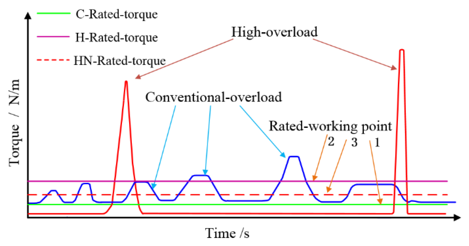
The feature of short-term high overload motor is that the maximum output torque is several times higher the torque of the rated load in the STHO-PMSM than in the conventional motor during a short time. Figure 1 presents the operating conditions of the conventional motor and the typical STHO-PMSM. It can be clearly seen that the maximum output torque of short-term high overload motors is significantly larger than the torque of conventional motor, but the overload time is relatively short. In general, the size of the motor is designed based on the calculated torque and the overload multiple of the motor is 2 to 3 times. Therefore, the calculated torque points of the conventional motor and the high overload motor are respectively set at curve 1 (C-Rated-torque) and curve 2 (H-Rated-torque) based on the general design ideas. However, due to high overload in a short time, it is feasible that the calculated torque points can be changed from curve 2 to curve 3 (HN-Rated-torque) when the higher electromagnetic load is designed. This also means an increase in the ultimate torque density in a short period of time. At the same time, some problem, i.e., higher copper loss and magnetic saturation of iron core, will also appear even though the time is short. Therefore, it is very important to focus on the motor’s electromagnetic thermal performance which can be accurately and quickly calculated so that the plan can be judged according to whether the calculated torque point meets the requirements. Obviously, the MMA method is a relatively simple and fast calculation method, which can reduce the computational time when a preliminary plan is selected.
2.2. Electrical Load
If an electrical machine is considered to have N turns of winding in each phase carrying a current I and the windings are represented in an equivalent current sheet around the airgap perimeter, the linear current density A for a unit length, which is also known as the electrical load, can be described as [19,35]:
where m represents the number of phase windings, is the stator inner diameter. Since the flux density B is known as the magnetic load, the electromagnetic torque T can be written as [19,36]:
where Vil is the volume of the stator inner diameter. It can be expressed as:
where Lef is the stator stack length. Thus from (1) and (3), (2) can be rewritten as:
From Equation (4), it is obvious that the electromagnetic torque is proportional to stator inner surface area (), magnetic load, and ampere-turns. In general, Dil and Lef are constrained by structure sizes in the design, which is unable to achieve high overload. Therefore, in the preliminary design process, make it a constant when analyzing the electromagnetic load.
Assume that the ampere-turns is defined by:
where its value is restricted by the maximum voltage. The specific relationship when using id = 0 control strategy is expressed as:
where E0 is the no-load back electromotive force (EMF), R is the phase winding resistance, Xq is the q-axis inductive reactance, U is the maximum value of the rms phase voltage.
Based on (6), Equation (5) can be expressed in the function form of the variable N as:
where:
with three coefficients are given by:
where f is the electrical frequency, Kdp is the winding factor related to the winding distribution, KΦ is the air gap flux waveform coefficient associated to the polar arc coefficient, bm0 is the PM working point, Am is the magnetic flux area per pole, Br is the residual magnetic density, σ0 is the magnetic flux leakage coefficient, ρcu is the copper resistivity, d is the copper diameter, Λ is the q-axis permeance.
According to Equations (7) and (8), the function f (N) of the extreme ampere-turns (when the expression (6) is an equation) can be derived as:
where:
To obtain the relationship between the turns N and extreme ampere-turns f (N), three coefficients which are kE = 0.00154, kR = 0.875 in the case where the basic parameters such as the poles-slots, the stator shape, and the operating frequency are determined, and kX = 3.17 × 10⁻⁴ are given through basic experience and approximate preliminary estimates [37]. U which equals 65.33 V is calculated by the DC bus voltage.
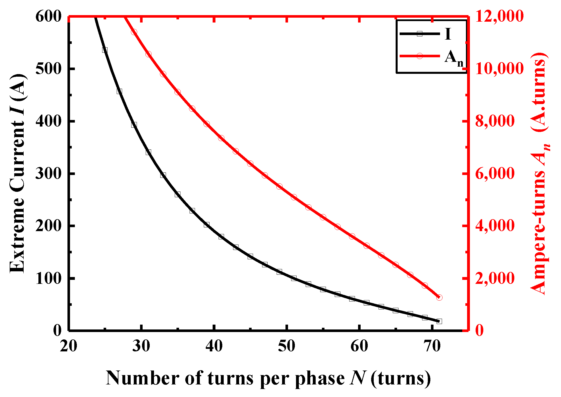
Equations (10) and (11) can be represented in Figure 2, where the number of turns N is within a reasonable range.
As can be seen in Figure 2, as the turns number N of each phase winding decreases, the ampere-turns An and extreme current I increase, respectively. The smaller the number of turns, the faster the growth rate. This is mainly that magnetic flux linkage becomes smaller for smaller turns leading to the smaller back EMF, as a result, the current can become larger under the constraints of the maximum voltage. Besides, impedance reduction because of the number of turns decreasing is beneficial to the increase of the extreme current. The rate at which the extreme current increases is greater than the rate at which the number of turns decreases, thus Ampere-turns increase with the reduction in the number of the turns. This also means that the extreme torque can have a significant increase to achieve the requirements of short-term high overload by reducing the number of winding per phase winding.
2.3. Magnetic Load
The magnetic load of the motor is the average magnetic flux density along the air gap surface at no-load. Magnetic density is generated by the magnetic energy of PM which is closely related to the material and volume. Moreover, although magnetic flux leakage coefficient also affects the magnetic density, it can be roughly treated as a constant based on experience in the design. In case of the material and volume determination due to the economic cost and the restrictions on rotor size, the effective magnetic energy is different with the different working points. The external effective magnetic energy is expressed by:
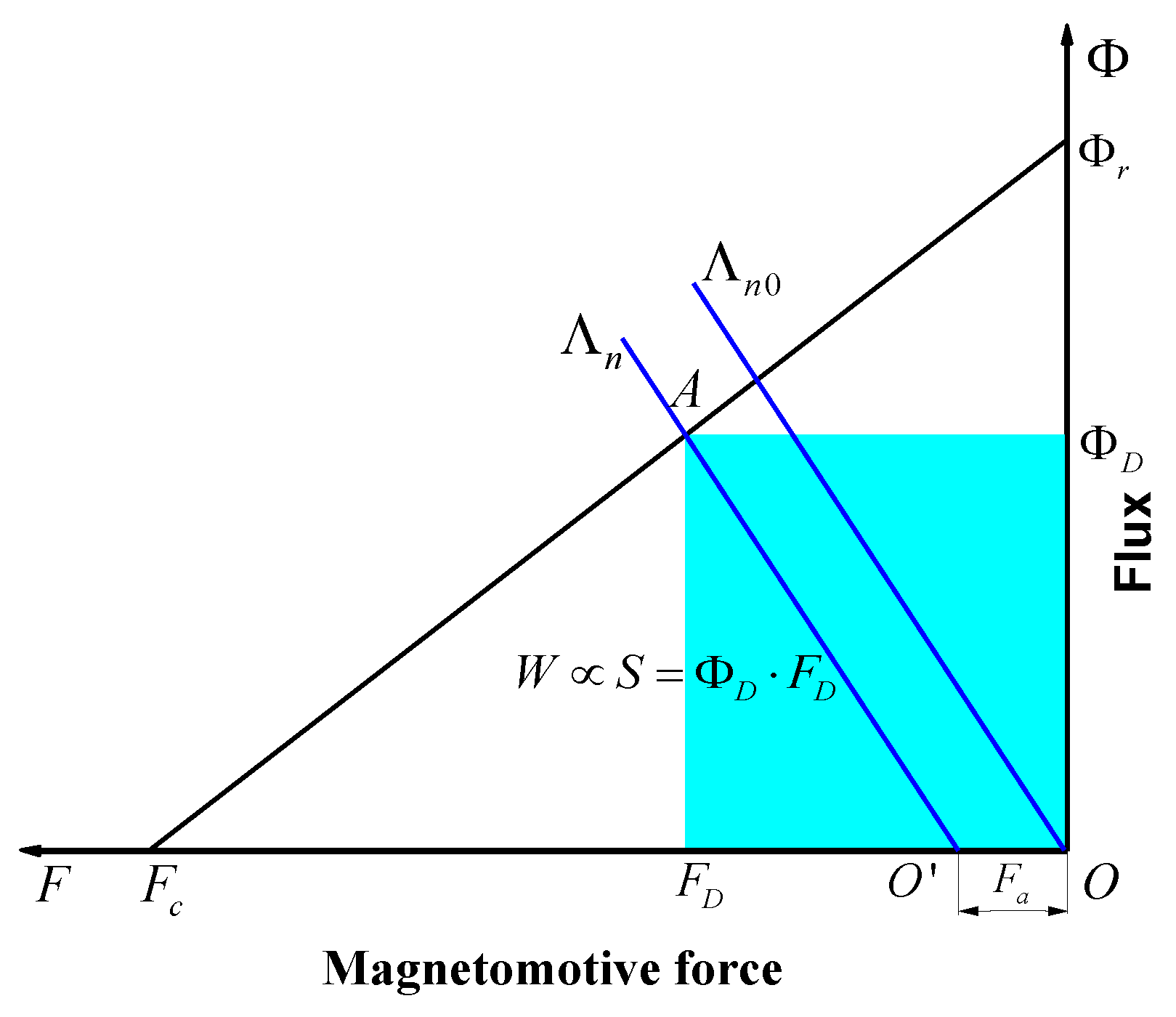
where ΦD and FD are the magnetic flux and the MMF, respectively, B and H are the magnetic density and the magnetic field intensity, respectively, Vm is the PM volume. The PM working point is given by:
where Φr and Fc, usually as a constant, are the virtual internal magnetic flux and coercive force, respectively. The PM working diagram is shown in Figure 3, where Fa is equivalent MMF in the outer magnetic circuit, Λn0 and Λn is synthetic magnetic permeance curves under no-load and load conditions, respectively. According to Equation (13), the area size of the square is proportional to the value of the effective magnetic energy in Figure 3. Assume S = ΦD·FD, according to Equation (14), the relationship between the effective magnetic energy and the PM working point is built by:
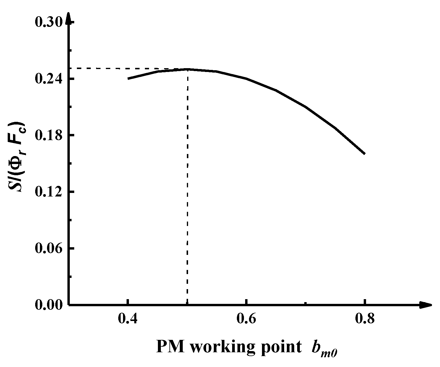
where the left side of the Equation (15) is proportional to the effective magnetic energy W. Considering that the PM working point is generally between 0.4 and 0.8, therefore, it can be observed in Figure 4 that S/(Φr·Fc) take the maximum and minimum when bm0 = 0.5 and 0.8, respectively. The ratio of the maximum to the minimum is 1.56 times which also means the maximum growth rate of the effective magnetic energy. Thus, the electromagnetic torque can ideally increase 1.56 times by adjusting the PM working point. However, this is not able to meet the requirements of short-term high-overload motor.
In summary, with the limited PM material and volume due to the economic cost and the restrictions on rotor size, meeting the requirement of high-overload multiples is too difficult to achieve high performance by changing the PM working point. Therefore, it is reasonable and necessary to reduce the number of windings per phase and increase the electrical load to achieve the high-overload multiples extreme torque. In addition, electrical load and magnetic load are also mutually influential that electrical load is related to the allowable slot area which can affect the size of the teeth and yoke. However, magnetic load is restricted by the saturation of the stator teeth and yoke. Therefore, both should take into consideration to be optimized in the design.
3. Consideration on the Nonlinear Saturation Effect
A remarkable feature of high-overload motor is that as the current greatly increases, iron core magnetic saturation is significant, then the torque coefficient decreases to limit the electromagnetic torque further increase. At the state of extreme torque output, the constraints of the magnetic density amplitude are as follows:
where Bt is the stator tooth magnetic density, By is the stator yoke magnetic density, Byr is the rotor yoke magnetic density, Bmax is the iron core maximum magnetic density. Therefore, only the magnetic saturation is considered, the extreme torque can be accurately calculated in the design.
3.1. Magnetic Reluctance Equivalent Network Model
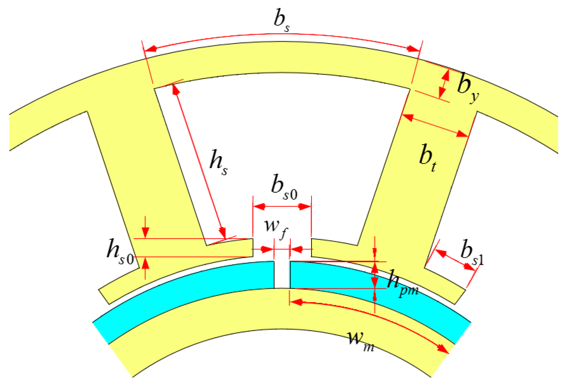
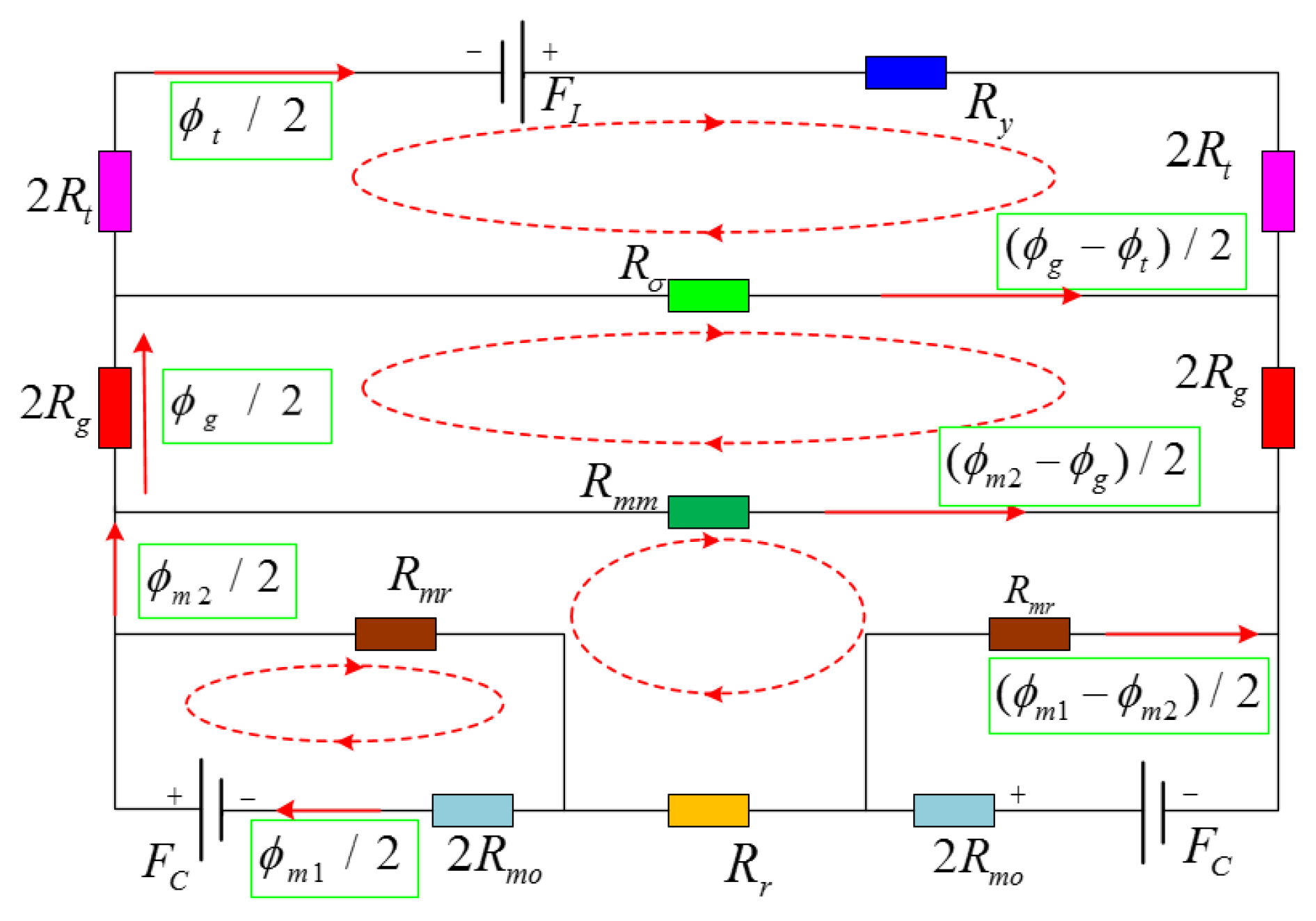
The key to magnetic circuit saturation is that magnetic permeability of the iron core decrease while magnetic density increases due to an increase torque. Therefore, the MMF on the iron core needs to be calculated in consideration of the nonlinear factors. Adopting the equivalent magnetic network model is an effective method for calculating magnetic field magnetomotive force. The basic structural parameters of the motor are shown in Figure 5. Equivalent magnetic network model is shown in Figure 6.
According to Figure 5, magnetic reluctances of the stator tooth core, the stator yoke core, the PM, the rotor yoke, and the air-gap are Rt, Ry, Rmo, Ryr, and Rg, respectively. Magnetic leakage reluctances of the tooth tip, the PM are Rσ, Rmr, and Rmm, respectively. Reluctances are calculated as follows [30,37,38]:
where μ0 is the air permeability, μrt, μry, μrm, and μryr are the relative permeability of Rt, Ry, Rmo, and Ryr. Dol, Dil are the stator outer diameter and inner diameter, bt is the tooth width, hs is the slot height, bs is the yoke length, hpm and wm are the thickness and width of the PM, byr is the rotor yoke width, wf is the PM gap, t is the pitch, bs0 is the slot opening width.
Equivalent air gap length ge can be written as:
where δ is the air gap length, Kδm which is the air gap coefficient of the PM can be expressed as:
where the slot width reduction factor σs is:
Then the magnet pole-to pole leakage flux and magnet-end leakage flux are calculated as:
Magnetomotive force of the armature and the PM are as follows:
where Ns is the number of conductors per slot.
According to Figure 6 based on Kirchhoff laws, the following equations can be expressed by:
where and are the flux of the tooth and air-gap, is the PM main flux, is the PM main flux after considering magnet-end leakage flux.
From Equations (28)–(31), four variables, which are , , , and , can be solved with four non-interfering equations. Then the air-gap magnetic density, tooth magnetic density, and yoke magnetic density can be calculated by magnetic reluctances Rg, Rt, and Ry, respectively.
3.2. Core Saturation Quantification
The decrease in magnetic permeability is due to core saturation. Measuring the level of saturation need to obtain the accuracy magnetic permeability. Equivalent permeability can be iteratively calculated by equivalent magnetic network model. Specific solution process is included in the design procedure of short-time high overload motor in the Section 5.
To quantify the level of the core saturation, the saturation torque discount factor k is defined in Equation (32):
where Tr is the actual torque generation, Ti is the ideal torque that does not consider the effect of the core saturation.
Electromagnetic torque can be derived by calculating the change rate of total energy stored in airgap [39], as shown in the following equation:
where (W’f)av is the total energy stored, Fsr is the airgap synthetic MMF, Fs and Fr are the airgap MMF generated by the stator winding and the PM, θ is the angle between Fs and Fr. When in ID = 0 control mode, θ = 90° and Fs = FI.
Then, substituting Equations (26) and (34) to (33), electromagnetic torque can be rewritten as:
From (35), it is evident that the electromagnetic torque is proportional to the armature current and the airgap MMF generated by the PM. Therefore, the load airgap MMF generated by the PM is equal to the difference of the no-load airgap MMF and the core MMF.
According to (32) and (35), saturation torque discount factor k can be also expressed by the MMF as follows:
where Frc and Frcn are the airgap MMF of load and no-load.
4. Thermal Performance Analysis
As mentioned above, due to the large electrical load, high-density motors can product a lot of heat. The heat in the slots, from where it can’t dissipate in a short time, making the temperature rise rapidly. This is harmful for the motor reliability. Therefore, it is necessary to calculate and analyze the temperature within the winding where the thermal hotspot is expected to occur.
4.1. Thermal Model
To quickly estimate the temperature rise, a thermal model is adopted as follows [22]:
where TCu, TFe, and TA are the temperature of the winding, the iron core, and ambient respectively, RCu, RFe, and Rh are the thermal resistances of the winding, the iron core, and house respectively, CCu and CFe are the heat capacity, PCu and PFe are the copper and iron losses, t is the operating time.
Convert Equations (37) and (38) to a matrix Equation (39):
where T, K, and Q are expressed as follows:
.
4.2. Iron and Copper
According to the Bertotti theory, the iron core loss can be divided into hysteresis loss, the eddy-current loss, and additional loss [40]:
where kh, kc and ke are the hysteresis loss coefficient, the eddy-current loss coefficient, and the additional loss coefficient, Bm is the peak flux density, f is the operating frequency, Vc is the core volume.
Copper loss can be calculated by:
where R0 is the initial resistance, α1 is the temperature coefficient of resistivity, T0 is the initial temperature.
5. Simulation Analysis
5.1. Design Procedure
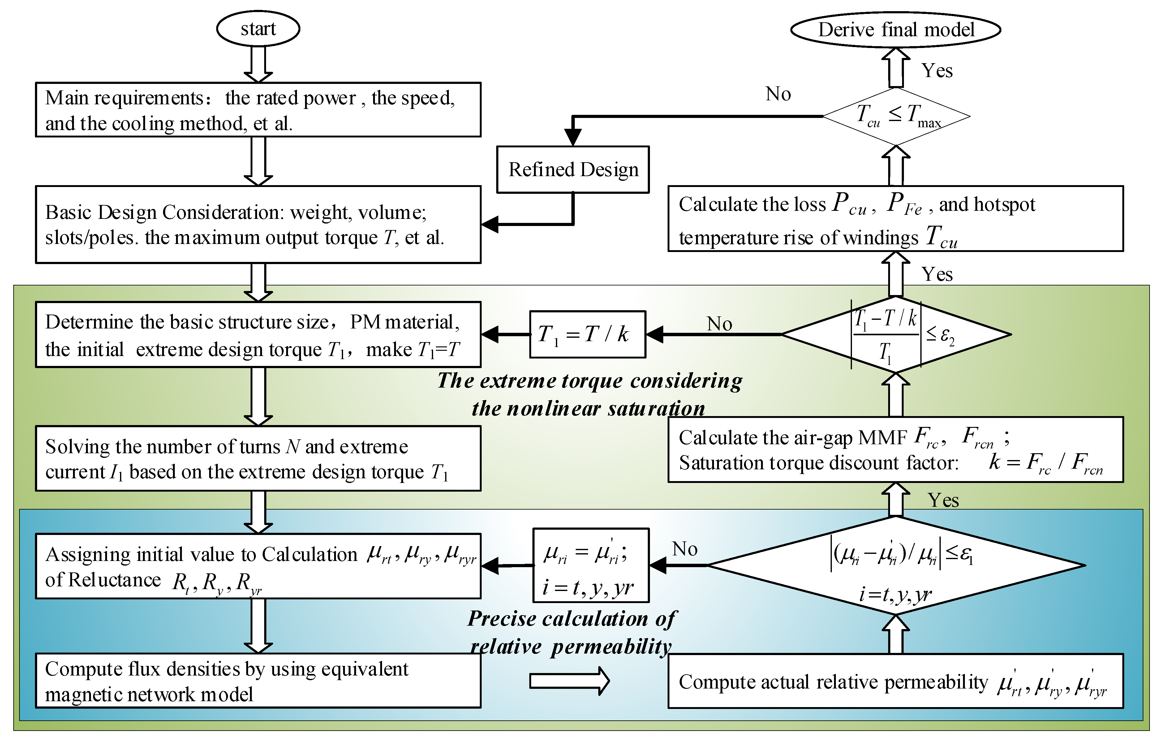
As shown in Figure 7, the design procedure with the equivalent magnetic network model and the thermal model is set. A rapid design of STHO-PMSM under the premise that achieve high-overload performance within the temperature allowable range can be obtained in the main process. Firstly, power, speed, torque, and basic parameter structure can be determined according to the requirement; Next, the number of winding turns and extreme torque can be calculated by Equations (7)–(12). Then, magnetic density can be obtained by using the equivalent magnetic network model with the initial iron core relative permeability, which calculated by the B-H curve. Iteration continues until the criterion is individually satisfied for all iron core relative permeability. Finally, saturation torque discount factor k can be computed by the no-load and load airgap MMF which are Frcn and Frc, respectively. In the case of initial determination of the electromagnetic design, verify that the temperature rise of the winding meets the indicator requirements. If the winding temperature is higher than the insulation level temperature Tmax, the motor should be re-size by adjusting the tooth width or the volume of the motor, etc. In such a repeated design process, the MMA method can obtain satisfactory design results faster than the FEA method.
5.2. Key Parameter Optimization
Since the STHO-PMSM focuses on the ultimate torque and maximum output torque density of the motor, the maximum torque and the volume are the key parameters. For the sake of the reliability requirements of the motor under extreme output conditions, the winding temperature should be considered. Therefore, three parameters will be optimized to improve the motor’s performance by adopting the MMA method when the motor basic structure parameters are roughly determined as in Table 1.
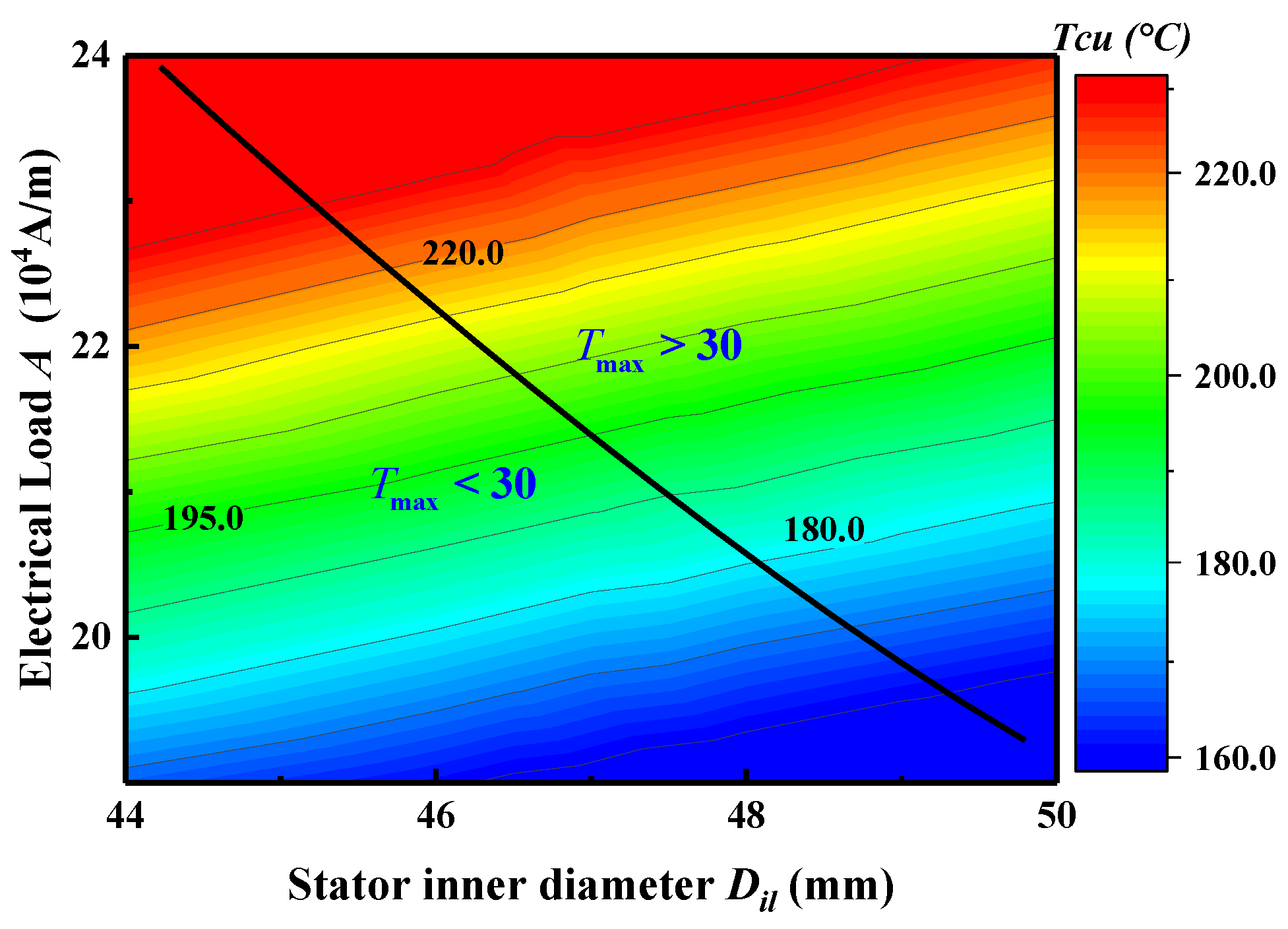
There are two constraints that have to be met in the optimizing design process: (1) The ultimate torque is ; (2) The winding temperature rise is °C after the ultimate torque output condition for 10 s. The stator inner diameter is approximate value ranged from 44 mm to 50 mm which can be computed according to the calculated torque 3.2 N·m and electrical load 210 A/cm. Then the initial value range of the maximum electrical load (19× 104~24 × 104 A/m) can be obtained by Equation (2).
The winding temperature rise can be obtained with different stator inner diameters and electrical loads as Figure 8 by using the design procedure considering the iron core nonlinear saturation in Figure 7. From Figure 8, the thick black solid line means that the torque is 30 N·m. Obviously, as the stator inner diameter increases, the electrical load can be designed to be smaller and the winding temperature is reduced. To satisfy two constraints, maximum output torque density (Tmax /V) can reach the maximum when stator inner diameter is designed to be 48 mm and the corresponding electrical load is 2060 A/mm. The calculation of the mathematical method takes 2 min in the process of optimization which is related to the selection range of parameters and initial permeability.
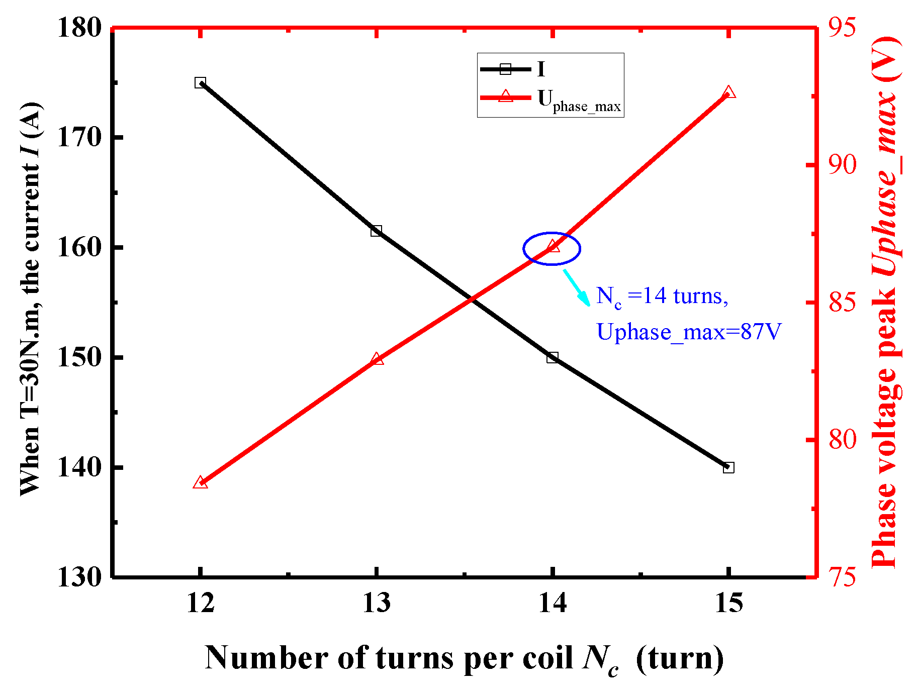
After the initial optimization by using the MMA method, the maximum Ampere-turns is designed to be 6300 A-turns. However, the extreme current of the motor and the peak magnitude of the voltage will be affected by the number of turns per coil. The MMA methods cannot accurately calculate phase voltage peak value under load conditions due to the distortion effect, so the FEA method will be adopted in the optimization process. Considering that the DC bus voltage is 160 V and the efficiency of the motor drive is about 95%, voltage peak value should be less than 87.5 V. At the same time, the small coil turns will increase the short-circuit current of the motor and reduce the voltage regulation. Therefore, it is appropriate that Nc is 14 turns according to Figure 9.
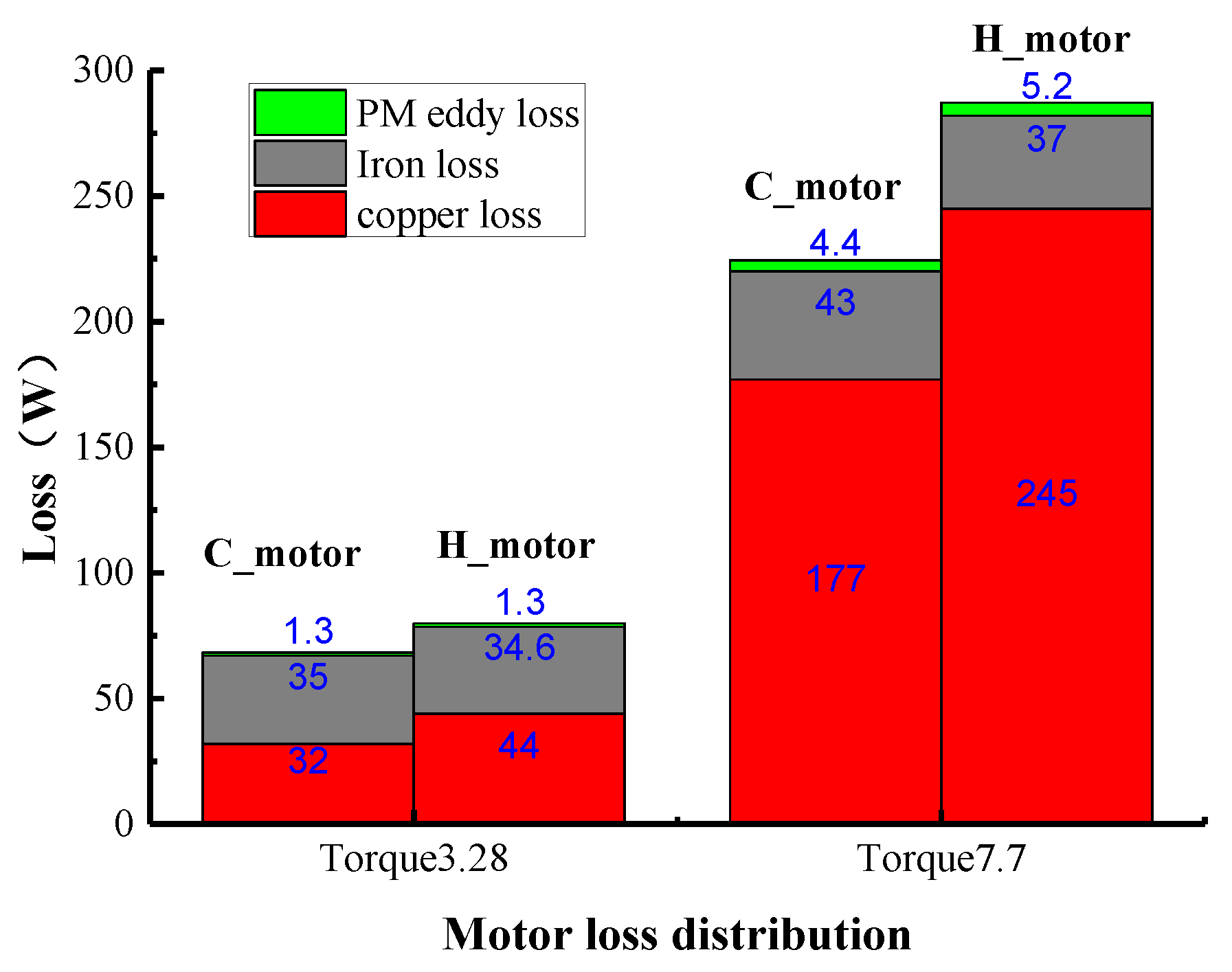
The loss is important that is related to the efficiency and the temperature rise of the motor. Therefore, a comparison will be analyzed between conventional motor (C-motor) and high overload motor (H-motor) with the same torque. Considering a longer run in the conventional motor, the computed electrical load is designed as 175 A/cm which is less than 210 A/cm in high overload motors. The number of windings per phase is 63 turns with 3.5 times the overload eventually. The loss distribution when the torque is 3.28 N·m and 7.7 N·m, respectively, is shown in Figure 10. The efficiency that the friction loss of the system and the drive’s efficiency is not considered is shown as the Table 2.
From the Figure 10, it can be obtained that copper loss in the high overload motors is higher than the conventional motor, iron loss and PM eddy loss is relatively little different with a same torque. This is mainly because the volume of high overload motor is relatively smaller, the working current will be correspondingly larger. Thus, as aforementioned before, the efficiency is about 0.7% and 1.6% lower than the conventional motor when the torque is 3.28 N·m and 7.7 N·m, respectively. The efficiency can be slightly lower, but it is acceptable that the working time is relatively short.
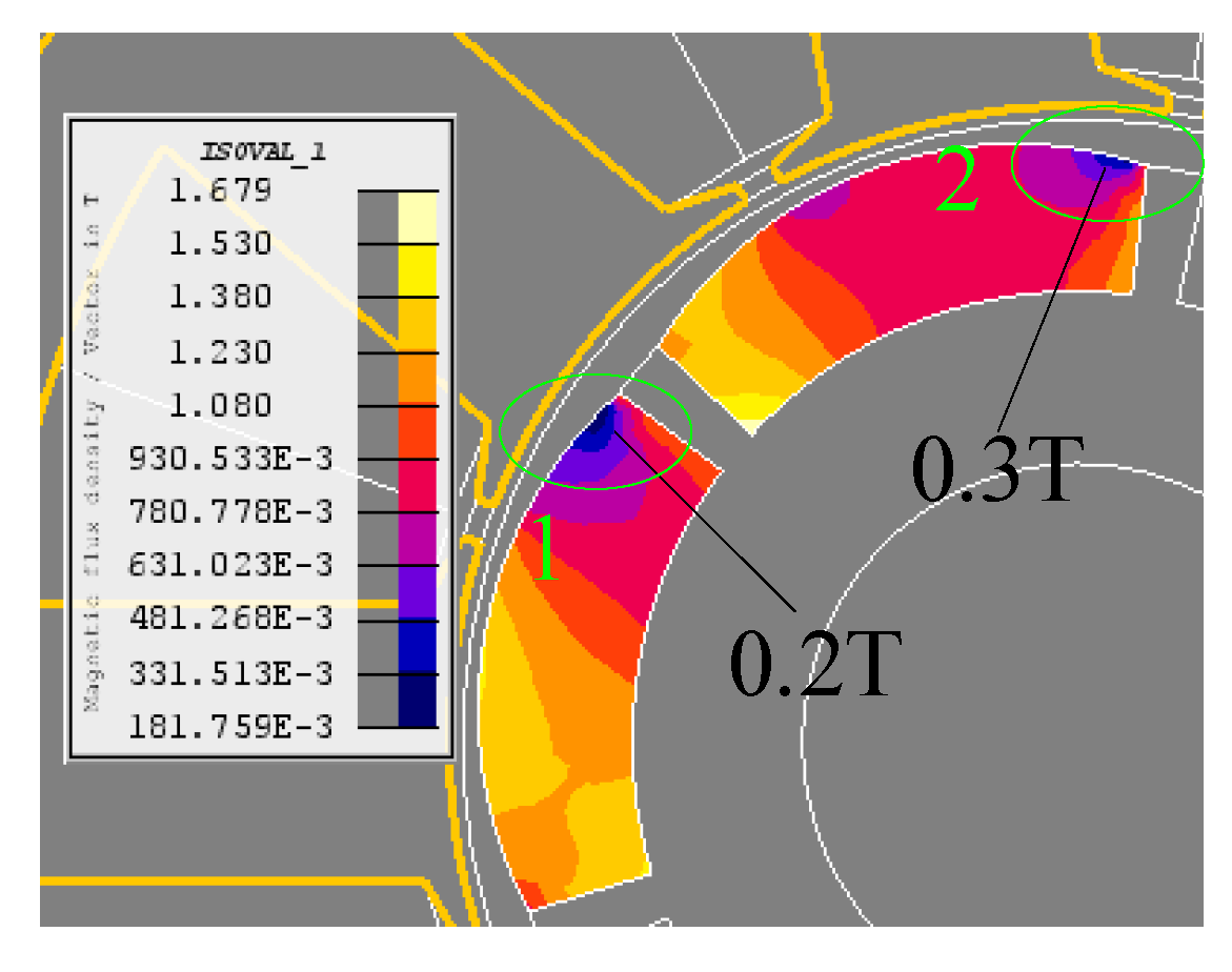
Since the working time is short under high overload conditions, the temperature rise of the PM is relatively low, which does not significantly affect the recovery curve of the PM. Even so, a large armature reaction may also make the PM prone to local demagnetization so much as to reduce the high performance of the motor. Magnetic density cloud map of the PM when the armature current is 150 A is shown as Figure 11. The minimum magnetic density of the PM is 0.2 T with a small area. By accessing information of the demagnetization curve that the PM material is N42SH and the temperature rate is 100 °C, the critical magnetic density of demagnetization is about 0.08T. Therefore, the PM do not suffer from the local demagnetization when the output torque is 30 N·m.
5.3. Electromagnetic Analysis
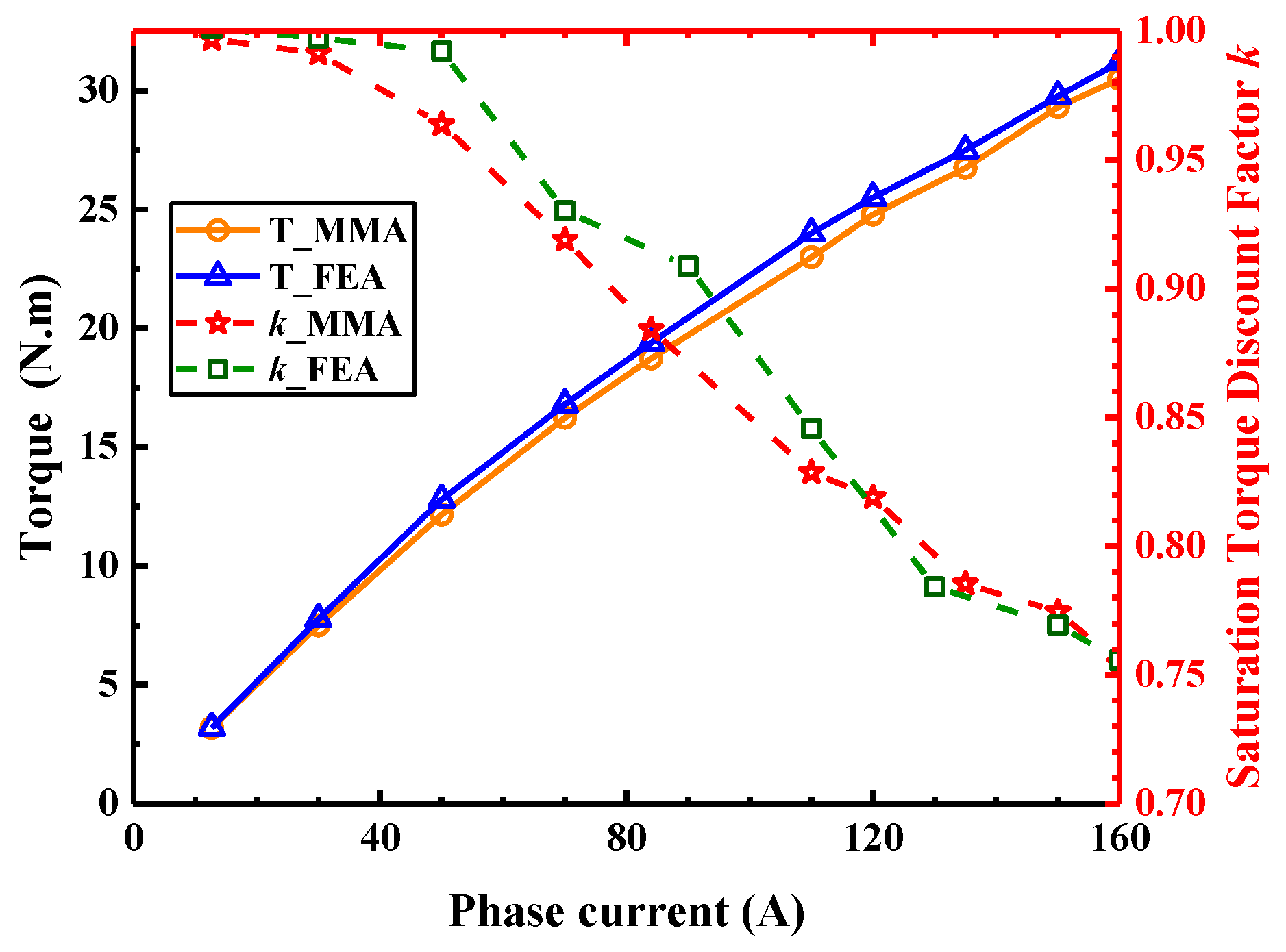
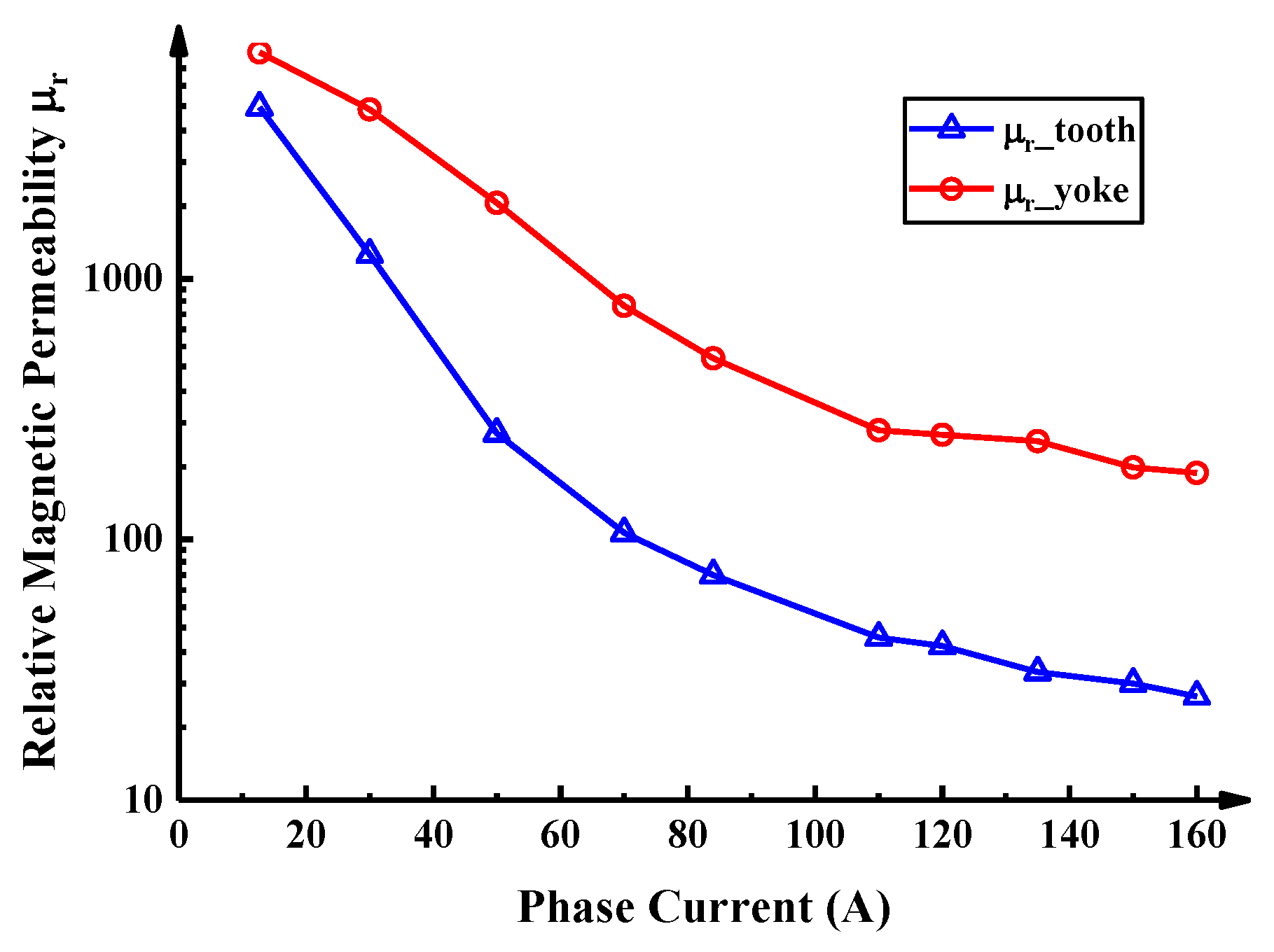
Through the repeated iteration and check with optimization by the designed procedure, motor basic structure parameters are obtained. The results of two calculation methods, the MMA and the FEA are shown as Figure 12. The simulation results show that the maximum torque can reach the 30 N·m which is around 9.4 times compared to the computed toque. The designed motor can achieve the performance of the high-overload. In addition, the torque does not increase proportionally to the current. High current makes the core saturation severe to decrease saturation torque discount factor. The results of the two methods have an acceptable consistency that the maximum errors of the torque and saturation torque discount factor are 5.0% and 2.1%, respectively. Relative permeability of the tooth and yoke is shown as Figure 13 whose ordinate is a logarithmic scale. From Figure 13, the relative permeability slowly decreases due to the saturation when the current is around 100 A. It is also indicated that the tooth is saturated severely than the yoke.
5.4. Thermal Analysis
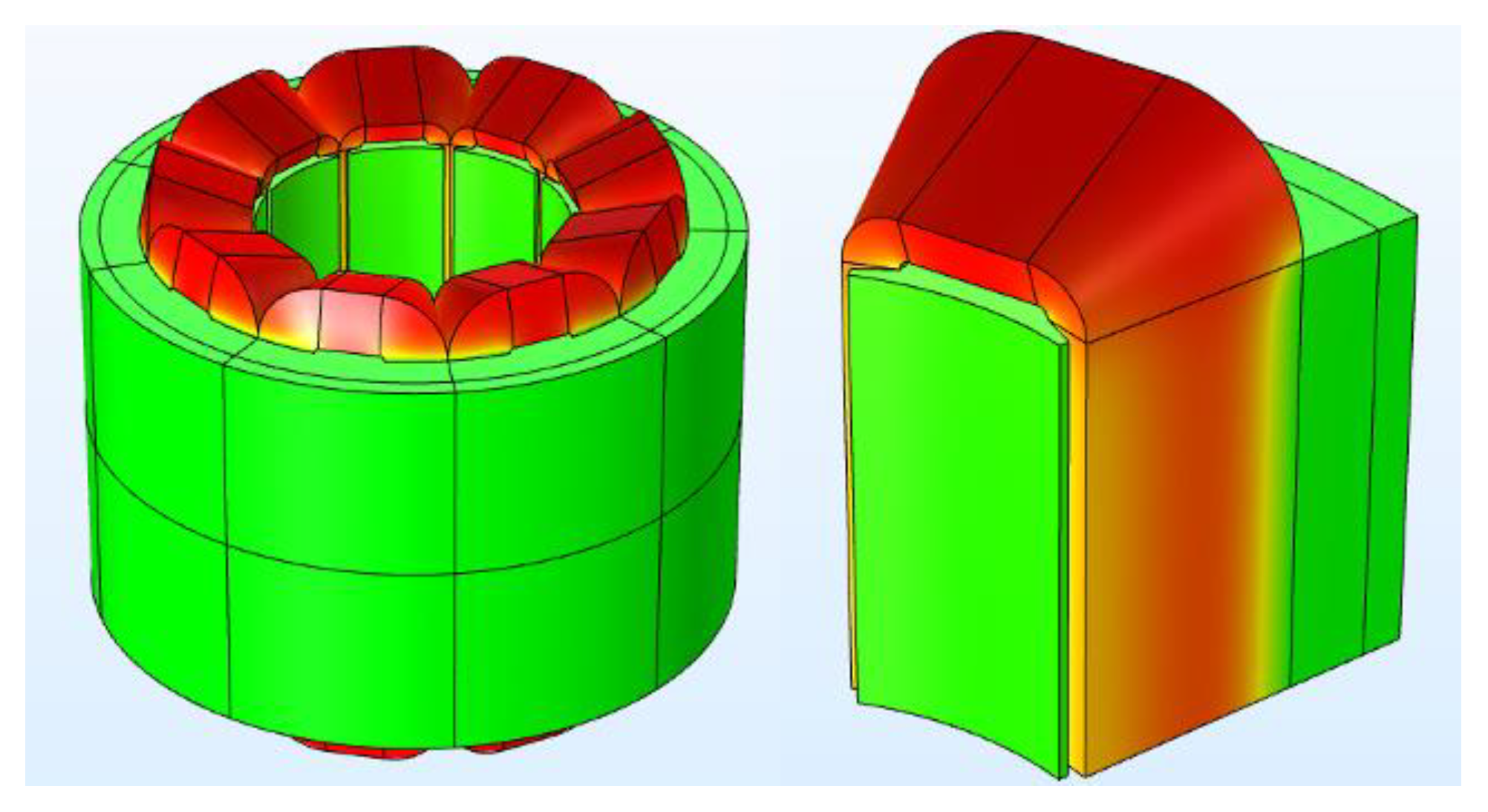
The purpose of the temperature winding calculation is to verify that the motor performance to meet the reliability requirements. Therefore, it is important to predict the temperature rise accurately. The temperature distribution of the stator and winding by using the FEA is shown as Figure 14 with three-dimensional temperature field analysis. The basic parameters of the equivalent winding [41] are that the heat capacity is 370 J/(kg·K), the density is 5050 kg/m3, and the thermal conductivity is 40W/(m·K). The equivalent thermal resistance of core and winding [21] are 0.103 °C/W and 0.036 °C/W, respectively.
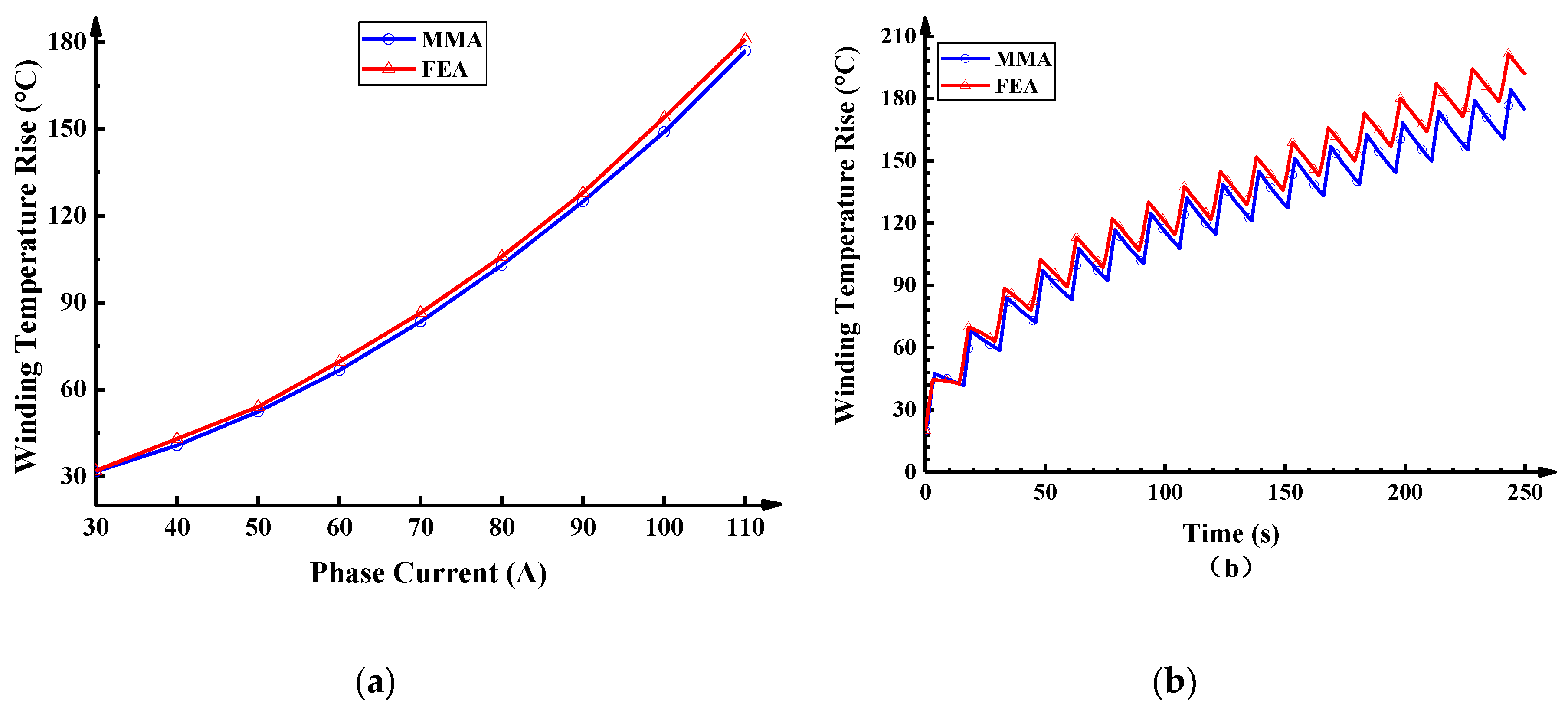
The results of the winding temperatures under two operating conditions are presented in Figure 15. From Figure 15a, it can be observed that, after the motor works continuously for 20 s, the results of the MMA and FEA agree that the maximum error is an acceptable 4.5%.
As can be seen in Figure 15b, though the operating time is short for 3 s accounts for a cycle of 20%, high current density due to the high-overload for 24 N·m make the winding temperature rise still gradually increase in the short duty cycle. The error slowly increases with the time, the maximum error can be 14.5% when the time is 250 s. Because that the rapid increase of winding temperature rise is mainly affected by the heat capacity in a short time, however, as the time increases, winding temperature rise is mainly influenced by the thermal conductivity and the heat capacity. Thus, excessive parameters lead to a larger error in simulation prediction. Through the comparison analysis of the electromagnetic and thermal, the MMA can obtain a relative accurate prediction. It can improve the optimization efficiency and reduce the design time.
6. Experimental Validation
6.1. Torque Validation
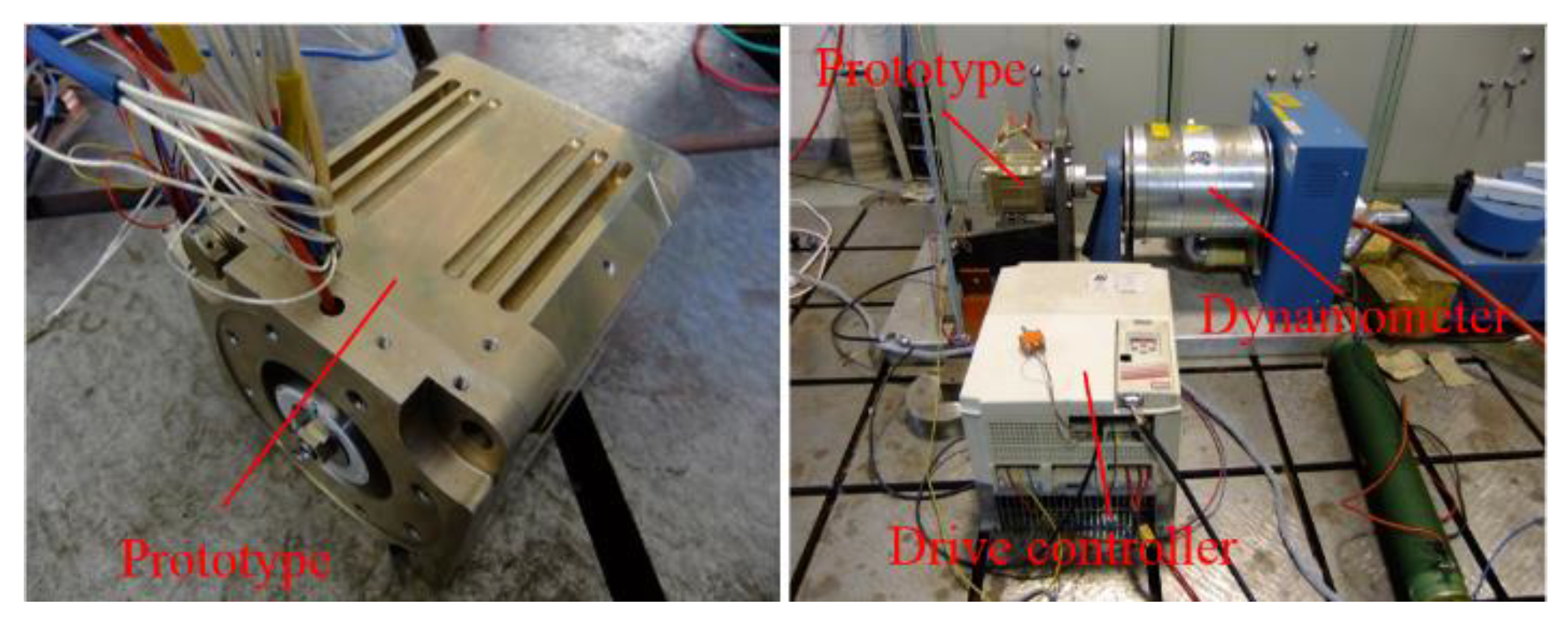
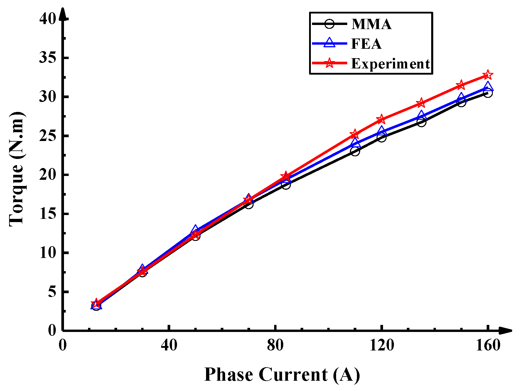
To test and verify the high-overload capability and the computational accuracy of the MMA and the FEA, a prototype is manufactured and the experimental platform is built as Figure 16. The torque can be obtained with the different current that the maximum current is 164 A. Then, the temperature of the end winding can be measured by the PT100 temperature sensors.
The torque measured in this experiment is compared with simulation result, as shown in Figure 17. It is evident that the experiment measurement agrees well with the results of the simulation when the torque is relatively small. As the current gradually increases, the difference in torque between the three methods is also slowly increasing, where the maximum errors of the MMA and the FEA are 7.0% and 4.9%, respectively. This is mainly because severe core saturation is difficult to quantify very accurately and effectively even although the lumped parameter equivalent magnetic circuit model is adopted in this paper. Besides, the motor can also achieve the high performance of the 10 times overload where the maximum output torque is 32 N·m compared to the computed torque 3.2 N·m in experiment measurement.
6.2. Temperature Validation
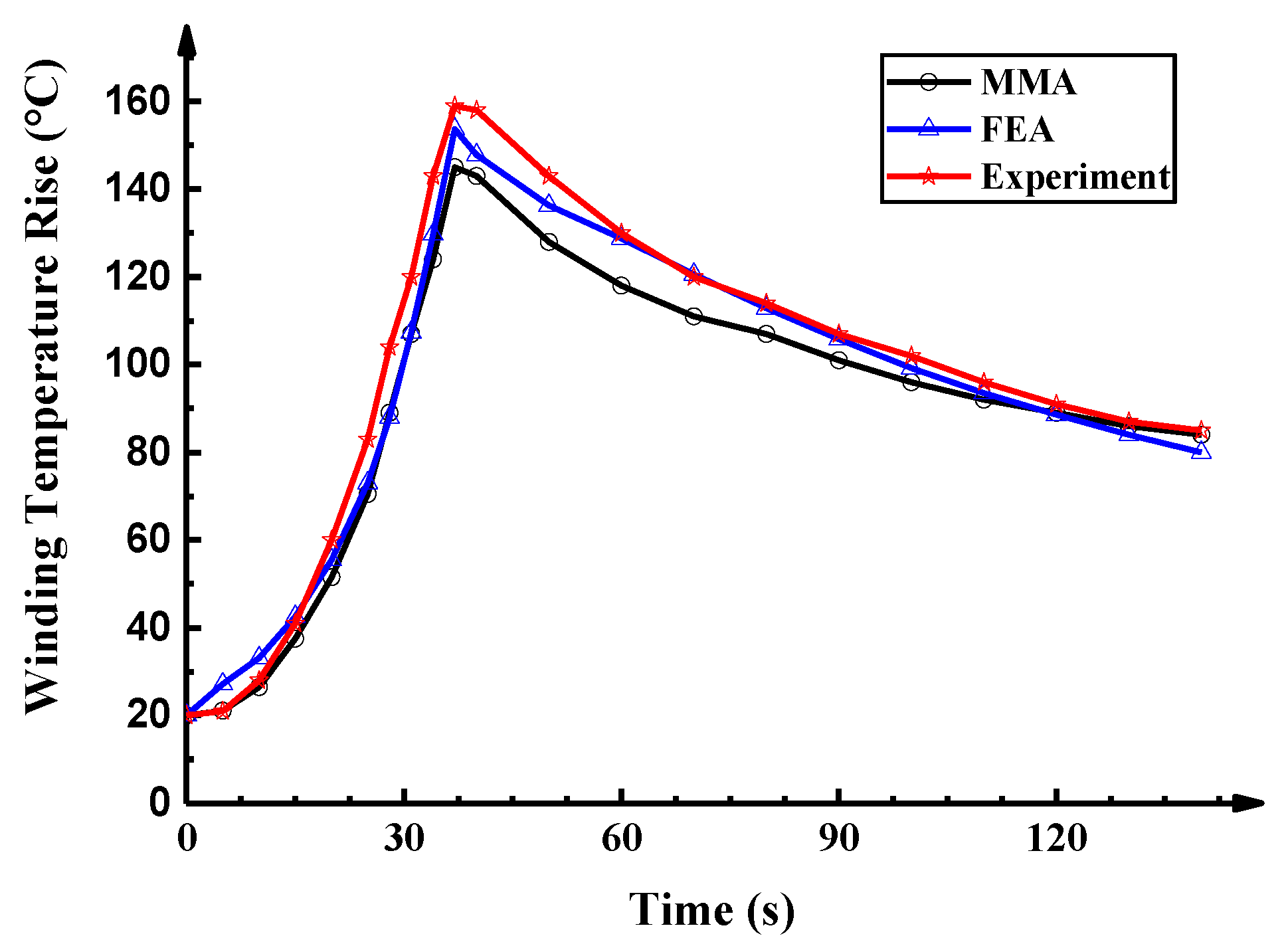
To prove the calculation accuracy of the temperature rise, the motor works continuously at different current densities for 37 s as shown in Table 3. Then the motor is cooled naturally for 113 s. When phase current is 30 A, the current density is 11.8 A/mm2.
As can be seen in Figure 18, as the current density increases, the rate of temperature rise increases rapidly in the experiment, the MMA, and the FEA models. The temperatures of the winding, when the time is 37 s, can reach 159 °C in the experiment, 145 °C in MMA, and 153.7 °C in FEA, respectively. During the natural cooling period, the curve consistency of the experiment and simulation results of the winding temperature decreases, compared to the period of temperature rises. The main reason is that as the time increases, the winding temperature rise is mainly affected by the thermal conductivity and the heat capacity. The thermal model of the motor housing and end cover are relatively complicated so that it is difficult to obtain an accurate model in the MMA.
A comprehensive analysis is that the torque and temperature results of the MMA and FEA can show a good agreement with experimental results. Therefore, it can be observed that the designed prototype can meet a high-overload performance and the mathematical model considering nonlinear saturation factors can predict the results of the design motor relatively accurately while the optimization and design time can be reduced.
7. Conclusions
In this paper, the design and optimization of a STHO-PMSM was presented and discussed. According to the operating conditions of the motor, the rated working point was optimized compared to the conventional design method. The effect of electromagnetic load on the extreme torque was analyzed in the proposed mathematical model. It was shown that the extreme torque can have a more significant increase to achieve the STHO-PMSM requirements by reducing the number of winding per phase winding. However, the electromagnetic torque can ideally only increased 1.56 times by adjusting the PM working point with limited PM material and volume. Besides, the effect of the nonlinear saturation on torque was quantified by the saturation torque discount factor that is the rate of the airgap MMF of load and no-load. The results of the two methods have an acceptable consistency that the maximum errors of the torque and saturation torque discount factor are 5.0% and 2.1%, respectively. A winding temperature model was presented to inspect the motor reliability of the design with the maximum error is 14.5%. The experimental results could also prove the same conclusion that STHO-PMSM can achieve the high performance of the high-overload in a short time. Additionally, the method of the MMA can relatively accurately predict as well as take less time consumption. A high overload multiple of the motor with 10 times overload is achieved. The research work in the future is mainly concerned about the heat dissipation of the STHO-PMSM because of high electrical load.
Author Contributions
Conceptualization, Y.-X.L., L.-Y.L., and C.-J.W.; Formal analysis, Y.-X.L., Q.-H.G.; Investigation, J.-W.C.; Methodology, Y.-X.L., L.-Y.L.; Software, Y.-X.L., Z.-Y.S., and J.-P.Z.; Supervision, L.-Y.L.; Writing—original draft, Y.-X.L.; Writing—review & editing, Z.-Y.S.
Funding
This work is supported in part by the National Natural Science Foundation of major projects under Grant 51690182, in part by the National Natural Science Foundation of China Youth Fund under Grant 51507036, and in part by the International Postdoctoral Exchange Fellowship Program under Grant 20171023.
Conflicts of Interest
The authors declare no conflict of interest.
References
- Tessarolo, A. A Quadratic-Programming Approach to the Design Optimization of Fractional-Slot Concentrated Windings for Surface Permanent-Magnet Machines. IEEE Trans. Energy Convers. 2018, 33, 442–452. [Google Scholar] [CrossRef]
- Fan, T.; Li, Q.; Wen, X. Development of a High Power Density Motor Made of Amorphous Alloy Cores. IEEE Trans. Ind. Electron. 2014, 61, 4510–4518. [Google Scholar] [CrossRef]
- Boglietti, A.; Cossale, M.; Vaschetto, S.; Dutra, T. Winding Thermal Model for Short-Time Transient: Experimental Validation in Operative Conditions. IEEE Trans. Ind. Appl. 2018, 54, 1312–1319. [Google Scholar] [CrossRef]
- Chen, Y.; Yang, Y.; Shen, Y. Influence of Small Teeth on Vibration for Dual-Redundancy Permanent Magnet Synchronous Motor. Energies 2018, 11, 2462. [Google Scholar] [CrossRef]
- Chen, Y.; Chen, X.; Shen, Y. On-Line Detection of Coil Inter-Turn Short Circuit Faults in Dual-Redundancy Permanent Magnet Synchronous Motors. Energies 2018, 5, 662. [Google Scholar] [CrossRef]
- Zhao, J.; Liu, W.; Li, B.; Liu, X.; Gao, C.; Gu, Z. Investigation of Electromagnetic, Thermal and Mechanical Characteristics of a Five-Phase Dual-Rotor Permanent-Magnet Synchronous Motor. Energies, 2015, 8, 9688–9718. [Google Scholar] [CrossRef] [Green Version]
- Cao, Z.; Li, W.L.; Li, J.; Zhang, X.; Li, D.; Zhang, M. Research on the Temperature Field of High-Voltage High Power Line Start Permanent Magnet Synchronous Machines with Different Rotor Cage Structure. Energies 2017, 10, 1829. [Google Scholar] [CrossRef]
- Xiao-Hai, L.; Zhu, L.; Ji-Min, Z.; Jiang, S.Z. Research on special low-speed, high-torque permanent magnet synchronous motor for screw pump. In Proceedings of the 2009 IEEE 6th International Power Electronics and Motion Control Conference, Wuhan, China, 17–20 May 2009; pp. 1858–1862. [Google Scholar]
- Huang, X.Z.; Liu, J.X.; Zhang, C.M.; Li, L.Y. Calculation and Experimental Study on Temperature Rise of a High Overload Tubular Permanent Magnet Linear Motor. IEEE Trans. Plasma Sci. 2013, 41, 1182–1187. [Google Scholar] [CrossRef]
- Kim, M.J.; Cho, S.Y.; Lee, K.D.; Lee, J.J.; Han, J.H.; Jeong, T.C.; Kim, W.H.; Koo, D.H.; Lee, J. Torque Density Elevation in Concentrated Winding Interior PM Synchronous Motor with Minimized Magnet Volume. IEEE Trans. Magn. 2013, 49, 3334–3337. [Google Scholar] [CrossRef]
- Qiu, H.; Yu, W.; Tang, B.; Mu, Y.; Li, W.; Yang, C. Study on the Influence of Different Rotor Structures on the Axial-Radial Flux Type Synchronous Machine. IEEE Trans. Ind. Electron. 2018, 65, 5406–5413. [Google Scholar] [CrossRef]
- Jun, H.W.; Lee, J.W.; Yoon, G.H.; Lee, J. Optimal Design of the PMSM Retaining Plate With 3-D Barrier Structure and Eddy-Current Loss-Reduction Effect. Trans. Ind. Electron. 2018, 65, 1808–1818. [Google Scholar] [CrossRef]
- Wang, J.; Yuan, X.; Atallah, K. Design Optimization of a Surface-Mounted Permanent-Magnet Motor with Concentrated Windings for Electric Vehicle Applications. IEEE Trans. Veh. Technol. 2013, 62, 1053–1064. [Google Scholar] [CrossRef]
- Min, S.G.; Bramerdorfer, G.; Sarlioglu, B. Analytical Modeling and Optimization for Electromagnetic Performances of Fractional-Slot PM Brushless Machines. IEEE Trans. Ind. Electron. 2018, 65, 4017–4027. [Google Scholar] [CrossRef]
- Chung, S.U.; Kim, J.M.; Koo, D.H.; Woo, B.C.; Hong, D.K.; Lee, J.Y. Fractional Slot Concentrated Winding Permanent Magnet Synchronous Machine with Consequent Pole Rotor for Low Speed Direct Drive. IEEE Trans. Magn. 2012, 48, 2965–2968. [Google Scholar] [CrossRef]
- Ahsanullah, K.; Dutta, R.; Rahman, M.F. Analysis of Low-Speed IPMMs With Distributed and Fractional Slot Concentrated Windings for Wind Energy Applications. IEEE Trans. Magn. 2017, 53, 1–10. [Google Scholar] [CrossRef]
- Wang, K.; Gu, Z.Y.; Zhu, Z.Q.; Wu, Z.Z. Optimum Injected Harmonics into Magnet Shape in Multiphase Surface-Mounted PM Machine for Maximum Output Torque. IEEE Trans. Ind. Electron. 2017, 64, 4434–4443. [Google Scholar] [CrossRef]
- Scuiller, F.; Zahr, H.; Semail, E. Maximum Reachable Torque, Power and Speed for Five-Phase SPM Machine with Low Armature Reaction. IEEE Trans. Energy Convers. 2016, 31, 959–968. [Google Scholar] [CrossRef]
- Arumugam, P.; Amankwah, E.; Walker, A.; Gerada, C. Design Optimization of a Short-Term Duty Electrical Machine for Extreme Environment. IEEE Trans. Ind. Electron. 2017, 64, 9784–9794. [Google Scholar] [CrossRef] [Green Version]
- Fang, H.; Wang, D. A Novel Design Method of Permanent Magnet Synchronous Generator from Perspective of Permanent Magnet Material Saving. IEEE Trans. Energy Convers. 2017, 32, 48–54. [Google Scholar] [CrossRef]
- Boglietti, A.; Carpaneto, E.; Cossale, M.; Vaschetto, S. Stator-Winding Thermal Models for Short-Time Thermal Transients: Definition and Validation. IEEE Trans. Ind. Electron. 2016, 63, 2713–2721. [Google Scholar] [CrossRef]
- Buyukdegirmenci, V.T.; Krein, P.T. Induction Machine Characterization for Short-Term or Momentary Stall Torque. IEEE Trans. Ind. Appl. 2015, 51, 2237–2245. [Google Scholar] [CrossRef]
- Chen, X.; Wang, J.; Sen, B.; Lazari, P.; Sun, T. A High-Fidelity and Computationally Efficient Model for Interior Permanent-Magnet Machines Considering the Magnetic Saturation, Spatial Harmonics, and Iron Loss Effect. IEEE Trans. Ind. Electron. 2015, 62, 4044–4055. [Google Scholar] [CrossRef]
- Sciascera, C.; Giangrande, P.; Papini, L.; Gerada, C.; Galea, M. Analytical Thermal Model for Fast Stator Winding Temperature Prediction. IEEE Trans. Ind. Electron., 2017, 64, 6116–6126. [Google Scholar] [CrossRef] [Green Version]
- Huang, Z.Y.; Fang, J.C.; Liu, X.Q.; Han, B.C. Loss Calculation and Thermal Analysis of Rotors Supported by Active Magnetic Bearings for High-Speed Permanent-Magnet Electrical Machines. IEEE Trans. Ind. Electron. 2016, 63, 2027–2035. [Google Scholar] [CrossRef]
- Nerg, J.; Rilla, M.; Pyrhönen, J. Thermal Analysis of Radial-Flux Electrical Machines with a High Power Density. IEEE Trans. Ind. Electron. 2008, 55, 3543–3554. [Google Scholar] [CrossRef]
- Kim, W.H.; Kim, M.J.; Lee, K.D.; Lee, J.J.; Han, J.H.; Jeong, T.C.; Cho, S.Y.; Lee, J. Inductance calculation in IPMSM considering magnetic saturation. IEEE Trans. Magn. 2014, 50, 1–4. [Google Scholar] [CrossRef]
- Meessen, K.J.; Thelin, P.; Soulard, J.; Lomonova, E.A. Inductance Calculations of Permanent-Magnet Synchronous Machines Including Flux Change and Self- and Cross-Saturations. IEEE Trans. Magn. 2008, 44, 2324–2331. [Google Scholar] [CrossRef] [Green Version]
- Zhu, Z.Q.; Liu, Y. Analysis of Air-Gap Field Modulation and Magnetic Gearing Effect in Fractional-Slot Concentrated-Winding Permanent-Magnet Synchronous Machines. IEEE Trans. Ind. Electron. 2018, 65, 3688–3698. [Google Scholar] [CrossRef] [Green Version]
- Qu, R.H.; Lipo, T.A. Analysis and modeling of air-gap and zigzag leakage fluxes in a surface-mounted permanent-magnet Machine. IEEE Trans. Ind. Appl. 2004, 40, 121–127. [Google Scholar] [CrossRef] [Green Version]
- Bacco, G.; Bianchi, N.; Mahmoud, H. A Nonlinear Analytical Model for the Rapid Prediction of the Torque of Synchronous Reluctance Machines. IEEE Trans. Energy Convers. 2018. To be published. [Google Scholar] [CrossRef]
- Wang, Q.S.; Niu, S.X.; Yang, L. Design Optimization and Comparative Study of Novel Dual-PM Excited Machines. IEEE Trans. Ind. Electron. 2017, 64, 9924–9933. [Google Scholar] [CrossRef]
- Li, Q.W.; Dou, M.F.; Tan, B.; Zhang, H.; Zhao, D. Electromagnetic-Thermal Integrated Design Optimization for Hypersonic Vehicle Short-Time Duty PM Brushless DC Motor. Int. J. Aerosp. Eng. 2016. [Google Scholar] [CrossRef]
- Lopez-Torres, C.; Garcia, A.; Riba, J.; Lux, G.; Romeral, L. Computationally efficient design and optimization approach of PMa-SynRM in frequent operating torque-speed range. IEEE Trans. Energy Convers. 2018. [Google Scholar] [CrossRef]
- Lekić, Đ.; Vukosavić, S. Split ratio optimization of high torque density PM BLDC machines considering copper loss density limitation and stator slot leakage. Int. J. Elec. Power Energy Sys. 2018, 100, 231–239. [Google Scholar] [CrossRef]
- Pyrhonen, J.; Jokinen, T.; Hrabovcova, V. Design of Rotating Electrical Machines, 2nd ed.; Wiley & Sons: Hoboken, NJ, USA, 2013; pp. 331–377. [Google Scholar]
- Elrefaie, A.M.; Zhu, Z.Q.; Jahns, T.M.; Howe, D. Winding Inductances of Fractional Slot Surface-Mounted Permanent Magnet Brushless Machines. COMPEL Int. J. Comput. Math. Elec. Electronic Eng. 2009, 28, 1590–1606. [Google Scholar] [CrossRef]
- Kou, B.; Jin, Y.; Zhang, H.; Zhang, L.; Zhang, H. Nonlinear Analytical Modeling of Hybrid-Excitation Double-Sided Linear Eddy-Current Brake. IEEE Trans. Magn. 2015, 51, 1–4. [Google Scholar] [CrossRef]
- Arumugam, P.; Hamiti, T.; Gerada, C. Analytical Modeling of a Vertically Distributed Winding Configuration for Fault Tolerant Permanent Magnet Machines to Suppress Inter-Turn Short Circuit Current Limiting. In Proceedings of the 2011 IEEE International Electric Machines & Drives Conference (IEMDC), Niagara Falls, ON, Canada, 15–18 May 2011; pp. 371–376. [Google Scholar]
- Mellor, P.H.; Wrobel, R.; Holliday, D. A computationally efficient iron loss model for brushless AC machines that caters for rated flux and field weakened operation. In Proceedings of the 2009 IEEE International Electric Machines and Drives Conference, Miami, FL, USA, 3–6 May 2009; pp. 490–494. [Google Scholar]
- Simpson, N.; Wrobel, R.; Mellor, P.H. Estimation of Equivalent Thermal Parameters of Impregnated Electrical Windings. IEEE Trans. Ind. Appl. 2013, 49, 2505–2515. [Google Scholar] [CrossRef]
Figure 1.
Operating conditions of conventional motor and short-term high-overload permanent magnet synchronous motor (STHO-PMSM).
Figure 1.
Operating conditions of conventional motor and short-term high-overload permanent magnet synchronous motor (STHO-PMSM).

Figure 2.
The influences of the number of turns on the extreme current and ampere-turns.

Figure 3.
The PM working diagram.

Figure 4.
Relative value change of the effective magnetic energy for different PM working point.

Figure 5.
The basic structural parameters of the motor.

Figure 6.
Equivalent magnetic network model.

Figure 7.
The design procedure of STHO-PMSM considering the iron core nonlinear saturation.

Figure 8.
Winding temperature rise with different stator inner diameter and electrical load for 10 s.
Figure 8.
Winding temperature rise with different stator inner diameter and electrical load for 10 s.

Figure 9.
The influence of the number of the coil turns on the current and phase voltage peak when T = 30 N·m.
Figure 9.
The influence of the number of the coil turns on the current and phase voltage peak when T = 30 N·m.

Figure 10.
A comparison of motor loss distribution.

Figure 11.
Magnetic density cloud map when armature current is 150 A.

Figure 12.
The torque and saturation torque discount factor comparisons at different current.

Figure 13.
The relative permeability change at different current.

Figure 14.
Temperature distribution of the stator and winding in a short time by using COMSOL.

Figure 15.
Calculated winding temperatures comparisons (a) different current for 20 s (b) short-time duty with high-overload.
Figure 15.
Calculated winding temperatures comparisons (a) different current for 20 s (b) short-time duty with high-overload.

Figure 16.
Experimental setup.

Figure 17.
The torque comparisons of the experiment measurement and simulations at different current.
Figure 17.
The torque comparisons of the experiment measurement and simulations at different current.

Figure 18.
The temperature comparisons of the experiment measurement and simulations.


Table 1.
Main design parameters of the short-term high-overload permanent magnet synchronous motor (STHO-PMSM).
Table 1.
Main design parameters of the short-term high-overload permanent magnet synchronous motor (STHO-PMSM).
| Parameters | Values | Parameters | Values |
|---|---|---|---|
| DC bus voltage/(V) | 160 | Rated speed/(r/min) | 4000 |
| Poles/slots | 6/9 | Stator split ratio | 0.51 |
| calculated torque/(N.m) | 3.2 | Electrical load/(A/cm) | 210 |
| Airgap length/(mm) | 0.8 | Magnetic load/(Tesla) | 0.65 |
| Radial length/(mm) | 62 | PM thickness/(mm) | 6 |
| Parallel tooth width/(mm) | 10.5 | Polar arc coefficient | 0.9 |
| Maximum output torque/(N.m) | 30 | Natural method | Natural cooling |
Table 2.
The efficiency with different torque.
| Efficiency | Torque = 3.28 N·m | Torque = 7.7 N·m |
|---|---|---|
| The conventional motor | 95.2% | 93.4% |
| The high overload motor | 94.5% | 91.8% |
Table 3.
Working time under different current density condition.
| Current Density (A/mm2) | Electrical Load (A/cm) | Working Time (s) |
|---|---|---|
| 11.8 | 501.6 | 5 |
| 15.7 | 667.3 | 5 |
| 19.7 | 837.3 | 5 |
| 23.6 | 1003.0 | 5 |
| 27.6 | 1173.0 | 5 |
| 31.4 | 1334.5 | 3 |
| 35.4 | 1504.5 | 3 |
| 39.3 | 1670.3 | 3 |
| 43.3 | 1840.3 | 3 |
| 0 | 0 | 113 |
© 2018 by the authors. Licensee MDPI, Basel, Switzerland. This article is an open access article distributed under the terms and conditions of the Creative Commons Attribution (CC BY) license (http://creativecommons.org/licenses/by/4.0/).
Share and Cite
MDPI and ACS Style
Liu, Y.-X.; Li, L.-Y.; Cao, J.-W.; Gao, Q.-H.; Sun, Z.-Y.; Zhang, J.-P. The Optimization Design of Short-Term High-Overload Permanent Magnet Motors Considering the Nonlinear Saturation. Energies 2018, 11, 3272. https://doi.org/10.3390/en11123272
AMA Style
Liu Y-X, Li L-Y, Cao J-W, Gao Q-H, Sun Z-Y, Zhang J-P. The Optimization Design of Short-Term High-Overload Permanent Magnet Motors Considering the Nonlinear Saturation. Energies. 2018; 11(12):3272. https://doi.org/10.3390/en11123272
Chicago/Turabian StyleLiu, Yu-Xi, Li-Yi Li, Ji-Wei Cao, Qin-He Gao, Zhi-Yin Sun, and Jiang-Peng Zhang. 2018. "The Optimization Design of Short-Term High-Overload Permanent Magnet Motors Considering the Nonlinear Saturation" Energies 11, no. 12: 3272. https://doi.org/10.3390/en11123272
Note that from the first issue of 2016, this journal uses article numbers instead of page numbers. See further details here.