Numerical Study of Flow Maldistribution in Multi-Plate Heat Exchangers Based on Robust 2D Model


Department of Cryogenic, Aeronautic and Process Engineering, Wroclaw University of Science and Technology, 50-370 Wroclaw, Poland
*
Author to whom correspondence should be addressed.
Energies 2018, 11(11), 3121; https://doi.org/10.3390/en11113121
Submission received: 18 September 2018
/
Revised: 21 October 2018
/
Accepted: 6 November 2018
/
Published: 12 November 2018
Abstract
:Plate heat exchangers (PHE) are characterized by high heat transfer efficiency and compactness. An exploitation problem of the PHE is related to flow maldistribution, which can make part of the PHE idle, resulting in overheating and damage. Making geometrical modifications to the PHE can help reduce flow maldistribution. Modifications should be kept to a minimum, so as not to complicate the production process. There is a large number of possible geometrical modifications, which simply considers additional obstacles or stream dividers. To test all of them would be impractical and would also take a prohibitively long amount of time to obtain experimental measurements. A typical PHE is characterized by a complex system of channels. Making numerical calculations of its 3D model can be prohibitively time and resource-consuming. The present work introduces a physically consistent methodology of the transformation of a real 3D geometry to its 2D representation. Its main novelty is to assure the same pressure drop balance remains between the 3D and 2D geometries. This is achieved by a preservation of the same cumulative pressure losses in both geometries. The proposed innovative approach levels the pressure balance difference by adding properly designed local geometrical modifications. The developed methodology allowed a wide range of parameter space and various geometrical modifications to be investigated, and revealed geometrical optimizations leading to the improved performance of the PHE. To minimize the influence of other factors, an incompressible and single-phase flow was studied.
1. Introduction
The plate heat exchanger (PHE) has a very efficient design but when compared to other design solutions, can demonstrate an important exploitation problem due to uneven flow distribution in the channels in-between its plates. The experimental and numerical findings of numerous authors confirm the existence of a flow maldistribution problem in practically every type of PHE design. The work of Mueller et al. provides a comprehensive review of different possible causes that may lead to flow maldistribution [1]. This may be provoked by mechanically driven factors such as fouling, fabrication tolerances, a bypass or poor header performance, or can also be related to the thermodynamic character of the ongoing processes (two-phase instabilities, heat transfer induced by changes of viscosity or density) [2].
The flow maldistribution problem is reported in non-phase-change applications [3,4,5,6] as well as in PHE condensers [7,8,9] and evaporators [10,11,12,13]. The uneven load of the PHE channels is especially undesirable in the case of evaporators. It can create dead zones in the farthest channels on the refrigerant side of the PHE and the vapor may be trapped in certain parts of the device, causing a local dry out or overheating. Hence, the overall heat transfer efficiency of the PHE may decrease significantly.
Many solutions to decrease the magnitude of the flow maldistribution have been proposed in different subcategories of the PHE, and they are mainly focused on inlet header design modifications. In the case of multi-stream plate fin exchangers, solutions include additional inlet baffles [14,15], rearranged channel configurations [16] or the introduction of internal two-phase distributors to the inside of the exchanger [17]. The work [11] shows the possible improvements that may be made to the performance of a two-stream PHE by an inlet distributor modification.
The flow maldistribution in the two-stream PHE can be potentially improved by simply rearranging the inlet and outlet locations. When the streams enter the devices from opposite sides of the PHE (Z-type), the mass flow across the flow channels are shown to be more evenly distributed compared to that of a (U-type) design [18]. However, the Z-type solution is not commonly preferred in HVAC installations for practical reasons, e.g., to reduce occupied space, and for maintenance and conservation.
The current studies are built on the assumption that flow maldistribution can be minimized with geometrical optimizations to the PHE. The easiest modification includes the introduction of additional obstacles or separators to the header pipe of the PHE. In practice, there is a large number of possible modifications. To examine all of them experimentally is impractical and would be greatly time consuming. Typically, cases like this would benefit from a virtual experiment. The main challenge in the numerical modeling of a real PHE is related to its very complicated geometry and the requirement of a high-resolution mesh to properly capture the flow as it relates to physics and heat transfer. Consequently, exploring a wide range of flow parameters and geometrical variations can be even more time consuming, or even impossible, for averaged-sized supercomputers [19]. This problem can be solved by an appropriately designed calculation methodology based on physically consistent simplifications that lead to a fast and reliable numerical model.
In our previous work [19], the properly designed 3D numerical mesh of a typical PHE was shown to consist of hundreds of millions of computational nodes. This is prohibitively too much for engineering applications, especially for flows with a phase change. Moreover, it makes the investigation of a wide range of parameter space and the geometrical modifications of a heat exchanger impossible. The current available research, which uses 3D numerical calculations, is limited to a single pair of plates [20] or focused on a precise detail of a 3D flow feature [21]. Opposite to this, if full geometry is being considered, 2D numerical calculations are still exploited [22].
The main objective of the present study is to create a robust methodology to transform the 3D geometry of a real PHE to its 2D representation. Consequently, fast and physically consistent calculations of a flow in the PHE are also made possible. In the above-mentioned author’s work [19], a reduction of the 3D geometry to its 2D representation has been successfully carried out and confirmed through comparison with experimental results. Nevertheless, the work only considered a single pair of plates (one flow channel). In the current studies, a multi-plate PHE is considered. This makes it possible to investigate the flow maldistribution phenomenon and different possible ways of reducing it.
The previously proposed methodology of the 2D reduction assured a preservation of geometrical and flow features, such as a channel Reynolds number and a mass flow. In the case of a multi-plate PHE, this is not enough because of significantly important differences in the pressure drop balance between the original 3D geometry and its 2D representation. The main novelty of the presently proposed numerical approach is in the development of a methodology assuring the same pressure drop balance between the 3D and 2D geometries. This is achieved by preserving the same cumulative pressure losses in both geometries. The author’s original idea was to level this difference in pressure balance by adding a properly designed local geometrical modification. This required a large number of careful numerical calculations to establish a trustworthy relation of this local pressure drop in the function of a Reynolds number.
Consequently, the proposed numerical methodology resulted in a computational mesh that was orders of magnitude smaller when compared to the original 3D geometry. This allowed a wide range of geometrical modifications and flow conditions to be investigated. In the current study, the main focus is placed on reducing flow maldistribution, which is seen as a purely hydrodynamic phenomenon. Therefore, to minimize the influence of other factors, an incompressible and single-phase flow was considered.
It is important to note that in the previously motioned work [19], a two-phase flow with evaporation was modeled. A satisfactory comparison with an experiment confirmed that consistent geometrical reductions can be applied in the case of more complex flows.
2. Mathematical Model
The numerical model used in this work is based on an open source Computational Fluid Dynamics (CFD) numerical toolbox, OpenFOAM (Open Source Field Operation and Manipulation) [23,24]. This is a C++ object-oriented library for solving complex problems in CFD, and for carrying out structural analyses. The robustness and trustworthiness of this open source software has been proven multiple times in diverse and challenging applications. Among which, the works [25,26,27] deal with nonstandard and very complex flow and heat systems.
Numerical calculations were made using the simpleFoam solver available in OpenFOAM (release 1612+). This solver exploits finite volume discretization in conjunction with the SIMPLE (Semi-Implicit Method for Pressure-Linked Equations) algorithm for incompressible flows. According to OpenFOAM documentation [23], simpleFoam is a steady-state solver for incompressible flows with turbulence modeling.
The vector field of the flow velocity is found by solving the Navier-Stokes equation for a steady flow of incompressible fluid [28]:
where is a velocity vector, p is pressure and is an effective kinematic viscosity calculated from selected transport and turbulence models.
3. Numerical Model and Transformation to 2D Geometry
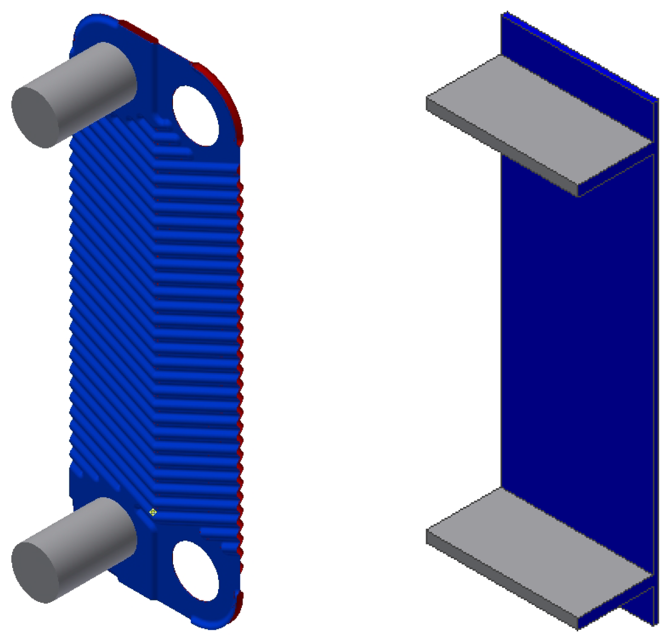
PHEs usually consist of a large number of perforated plates. Assembled together, they form a complicated net of flow channels. The perforation of the plates usually exploit a chevron pattern, Figure 1. The very complex net of flow channels intensifies the turbulence and consequently enhances heat transfer. The current investigation is based on a real PHE device used in the experimental work of [12]. The geometrical details and measures are listed in Table 1.
The geometrical complexity of the chevron plate results in a very complicated and dense numerical mesh. In the author’s previous work [19], the minimum size of the 3D computational mesh for one flow channel (two plates), for a moderate Reynolds number, was shown to consist of elements. A typical PHE has plates and its numerical model would require computational cells. Consequently, this would require an extremely lengthy amount of time for calculation and extensive hardware requirements.
Additionally, from an engineering perspective, the examination of a wide range of parameters is often necessary, with short computational time required. Consequently, full 3D computations can be prohibitively time and resource-consuming. This clearly motivates the need for a robust 2D reduction of the original 3D geometry.
An appropriate 2D reduction should preserve crucial dimensions, including: flow channel width , depth D (plate width) and the longitudinal height of the plates . This assures the same heat transfer area and channel Reynolds number:
where is the inletting mass flow, is the number of channels, is the hydraulic diameter of the channel and is a cross-sectional area and is viscosity. In the current study, a PHE with (60 plates) was considered.
The PHE headers and flow channels were simplified to 2D but their cross-sectional areas were preserved to match the 3D geometry. Consequently, the inlet velocity consistency was satisfied. This requirement determined the height of the rectangular 2D inlet section to be: = 7.4 mm, see Figure 2a.
To reproduce the chevron flow pattern inside the PHE channels without a substantial increase of the mesh size, zero-thickness mixing baffles inside the 2D flow channels were introduced. They were placed alternately on both plates, as shown in Figure 2c. Applying the mixing baffles allowed a wavy flow pattern to be reproduced. This was previously shown to be a critical aspect of the 3D to 2D transition [19]. The amount of mixing baffles applied was determined by the analysis of the considered real 3D PHE geometry, and was estimated to be equal to 26.
Another critical aspect of the 3D to 2D transformation, which has not been considered before, is related to the preservation of the pressure loss balance between the geometries. In the transformation from 3D to 2D geometry, there is a substantial change in the pressure loss balance. This is related to the different values for the hydraulic diameter of the header in the 3D geometry and its 2D representation. To even out the pressure loss balance, an originally designed approach has been proposed and is discussed in the next section.
Pressure Balance Analysis and Throttling Baffles
An analysis of the proposed 2D geometry, when compared to its 3D original, shows a discrepancy in pressure loss balance across the PHE. Although the rectangular 2D header was modeled to preserve the inlet cross-section area, it did not conserve the same hydraulic diameter as with the circular 3D header. Additionally, due to a change in shape of the inlets to the PHE flow channels from circular (and localized in the middle of plates) to rectangular, there is a difference in the local pressure drop as well, see Figure 1. Consequently, there is a greater linear pressure drop in the header pipes (bottom and top collector pipe) but less local losses at the inlets and outlets of the PHE flow channels in the case of the 2D geometry, compared to the 3D geometry. A general idea to level these differences is to assure the same cumulative pressure losses in both PHE geometries:
where and are the total pressure losses in the header of the 3D geometry and its 2D representation, respectively. and are the total pressure losses in the parallel channels of the PHE in the 3D geometry and its 2D representation, respectively. Further analysis assumes the same mass flow through each PHE channel (uniform flow distribution) and consequently, the same local and linear pressure loses in each individual channel.
It is justified to state that: and . The first inequality is obvious because the hydraulic diameter of the collector pipe of the 2D geometry is smaller than the hydraulic diameter of the corresponding 3D geometry, and can be proven by the Darcy-Weisbach formula. The second inequality is a hypothesis which will be checked numerically in the latter part of the paper.
Rearranging and expanding Equation (3) gives:
where and are the linear pressure losses in the header pipes of the 3D and 2D geometries, respectively, and are the local pressure loss coefficients at the inlet to the PHE channels of the 3D geometry and its 2D representation, respectively. and are the local pressure loss coefficients at the outlet of the PHE channels of the 3D geometry and its 2D representation, respectively. L is the length of the collector pipe and is a friction factor
In general , and . To fulfill Equation (4) an additional pressure loss must be included to assure:
The additional pressure losses: and were included in the 2D geometry as properly designed local losses in the form of additional throttling baffles at the inlets and outlets of the PHE channels (Figure 2b).
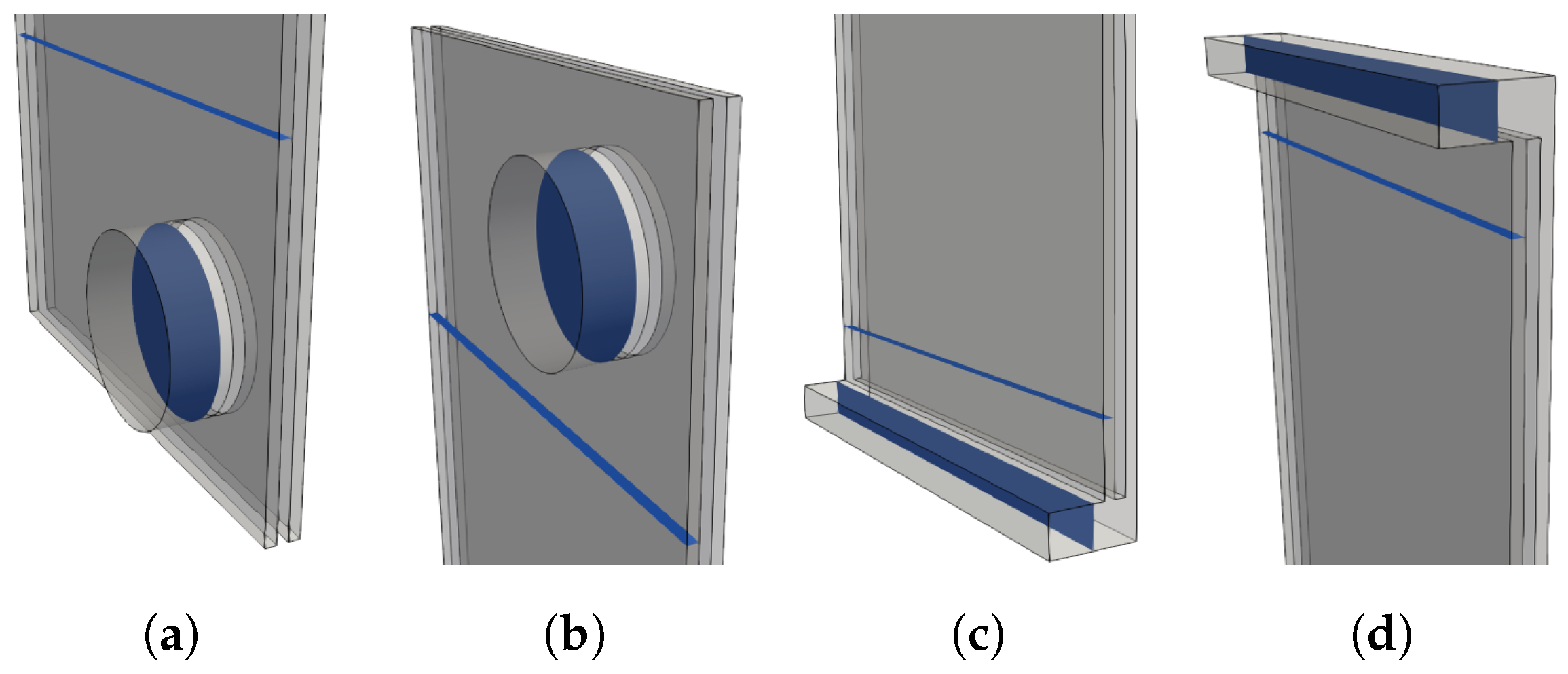
The local loss coefficients are unknown and need to be evaluated numerically. For this purpose, two models of the PHE were created and each of them contained only two flow passages (four plates). The first geometry was based on the 3D PHE model and had a circular tube header (Figure 3a,b), and the second model was based on the 2D PHE and had a rectangular duct header (Figure 3c,d). To assure an accurate estimation of the local loss parameters, both models were created as three-dimensional, and each mesh contained over 30 million computational cells satisfying the mesh independence requirement.
The estimated local loss coefficients were based on the numerical results of the pressure and velocity fields measured on surfaces coloured in blue in Figure 3 and calculated using: . The obtained numerical values of the local loss coefficients for the considered range of numbers are listed in Table 2. It can be seen, that the previously stated hypothesis: is proven. Interestingly, the ratio of is independent from and equals approximately 2.5 for the inlets and 2.0 for the outlets, despite the fact that the absolute value of the local loss coefficients have a tendency to decrease with .
Based on Table 2 and Equation (5), it was possible to determine the values of the additional loss coefficients at the inlet and outlet and to fulfill Equation (4). This was incorporated in the numerical model with additional throttling baffles. Their length was calculated using values of and . To make this possible, it was necessary to determine the functional dependency of coefficients from the throttling baffle size (the opening of an inlet and outlet of a PHE channel). In order to obtain these relations, a set of geometries with different baffle sizes was created. The influence of the bottom and top baffles were checked separately. The sizes of the inlet and outlet throttling baffle were changed gradually and the related pressure losses were calculated.
The measurements of the pressure and velocity needed to calculate the local loss coefficients in the function of the channel opening were done on the same surfaces as before (Figure 3c,d). Their numerical values, expressed as percentages of the clearance of the inlet and outlet to the channel, are presented in Table 3 and Table 4, respectively.
The additional linear pressure loss in the header was calculated using the Darcy-Weisbach formula [29] and was directly included in the local losses coefficients. The final sizes of the throttling baffles placed at the inlet and outlet of the PHE channels are shown in Table 5. It can be observed, that the length of the throttling baffles gradually get smaller with the .
4. Geometrical Modifications of PHE and Reduction of Flow Maldistribution
To decrease the intensity of the flow maldistribution and improve the performance of PHE, a number of different geometrical optimizations to the inlet header collector were examined. The main purpose of the proposed modifications was to force the fluid stream to enter the channels with a more uniformly distributed mass flow. The investigated geometrical changes are schematically shown in Figure 4 and summarized in Table 6. Their simplicity makes straightforward application possible in a real PHE. Consequently, all the configurations may be potentially applied in mass industrial production.
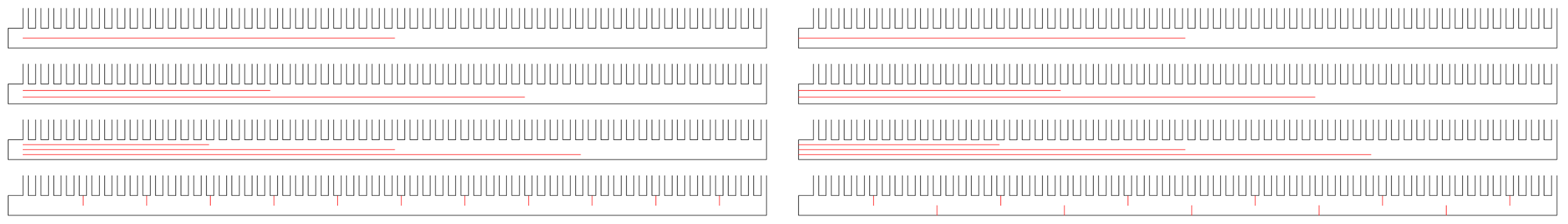
In the cases: 2str, 3str, 4str, 2str2, 3str2, 4str2 additional horizontal baffles (dividers) were introduced to the bottom header of the PHE to force a separation of the inletting fluid. Additionally, the influence of the placement of the starting point of the dividers was investigated, either from the first channel or from the beginning of the inlet header. These geometrical modifications were motivated by the expectation that the fluid would be redirected and delivered to different regions of the PHE. In the cases: TW-top, TW-alt vertical baffles were introduced instead of horizontal ones. Their goal was to enhance turbulence and mixing in the bottom header. Theses baffles were placed in every fifth channel and covered half of the header cross-section.
5. Results
In this work, flow maldistribution was evaluated based on a vertical component of the velocity vector in every channel of the PHE. The values of the velocity were read at a half height of the PHE. The mean velocity in every channel was calculated according to:
where is the y component of velocity in the i-th channel.
To discuss and compare the flow distribution between different numbers, the mass flow ratio coefficient was defined as:
where is the mass flow in the i-th channel and is the theoretical average mass flow in the channel, assuming the perfect distribution of the flow.
To evaluate and compare the results for different geometrical modifications, a degree of flow nonuniformity s was defined as an average of absolute deviation:
where average mass flow ratio is 1 by definition, and where s = 0 means there is an ideal flow distribution. Based on Equation (8), a degree of maldistribution parameter was defined as:
where is the worst possible maldistribution calculated using Equation (8) with the assumption that the whole flow goes through the first channel of the PHE. The value of changes from 0 to 1, where 1 means a uniform mass flow in every channel (no maldistribution).
5.1. Effect of on Flow Maldistribution
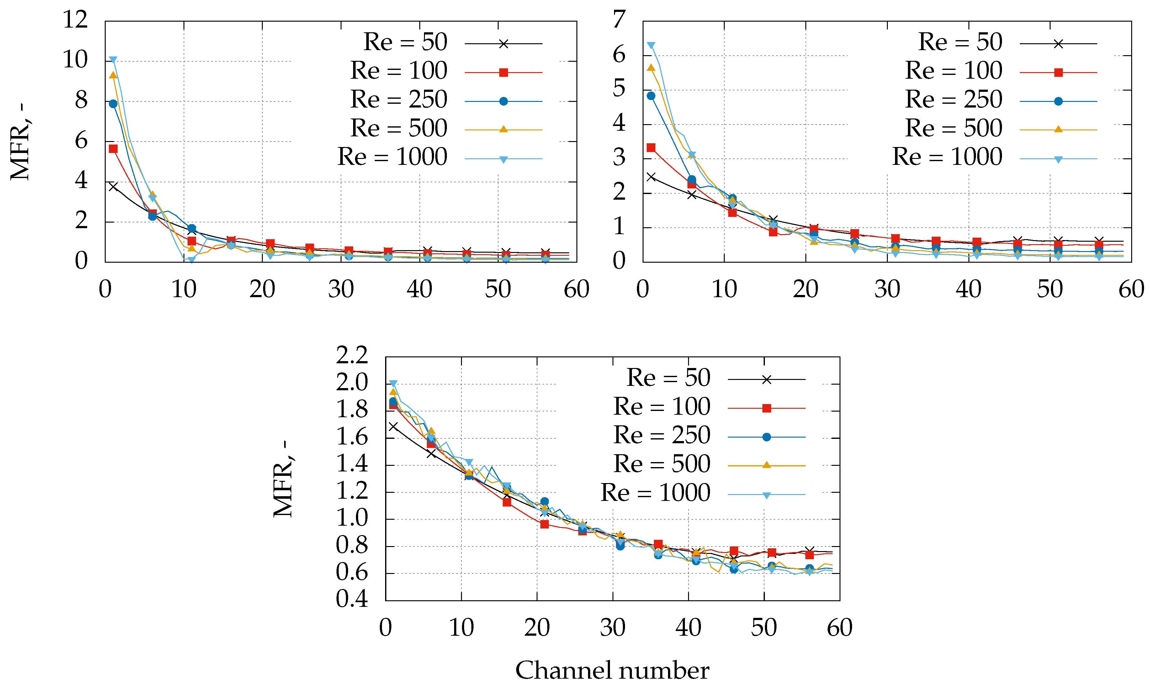
Figure 5 shows the effect of on the intensity of maldistribution. This compares the coefficients for the considered 2D models: org, org4 and org5 for . Note that the basic org geometry does not have mixing and throttling baffles and should be treated as reference results. The value of for these geometries are presented in Table 7.
The introduction of mixing and throttling baffles can be observed to have a crucial impact on the results. The differences between the org, org4 and org5 models are related to an inconsistent pressure drop balance as compared to the original 3D geometry (in the case of the org model). The pressure loss in the header of the org is too high in relation to the pressure drop in the channels, and the flow chooses “the easiest way” through the first few channels. Consequently, a higher flow maldistribution is observed. For every considered geometry, the intensity of the flow maldistribution grows with increasing . This is particularly visible in the reference case org. It should be noted that these tendencies become substantially smaller in the more realistic model of the 2D PHE. For org5, this dependency is very weak, and can be seen in the bottom image of Figure 5. Nevertheless, the flow maldistribution is considerably strong in every case.
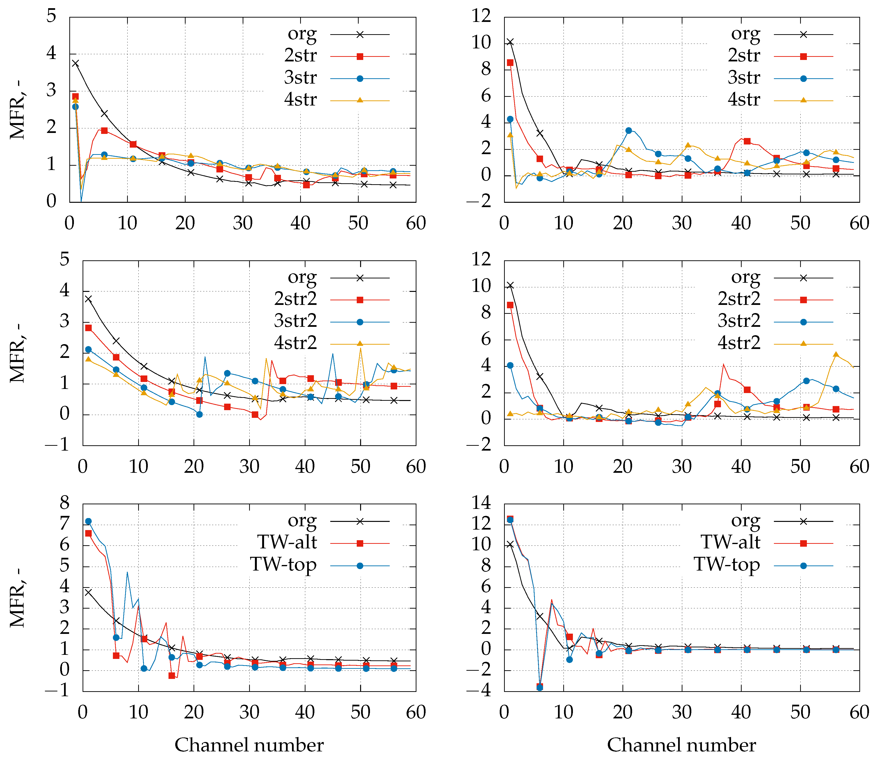
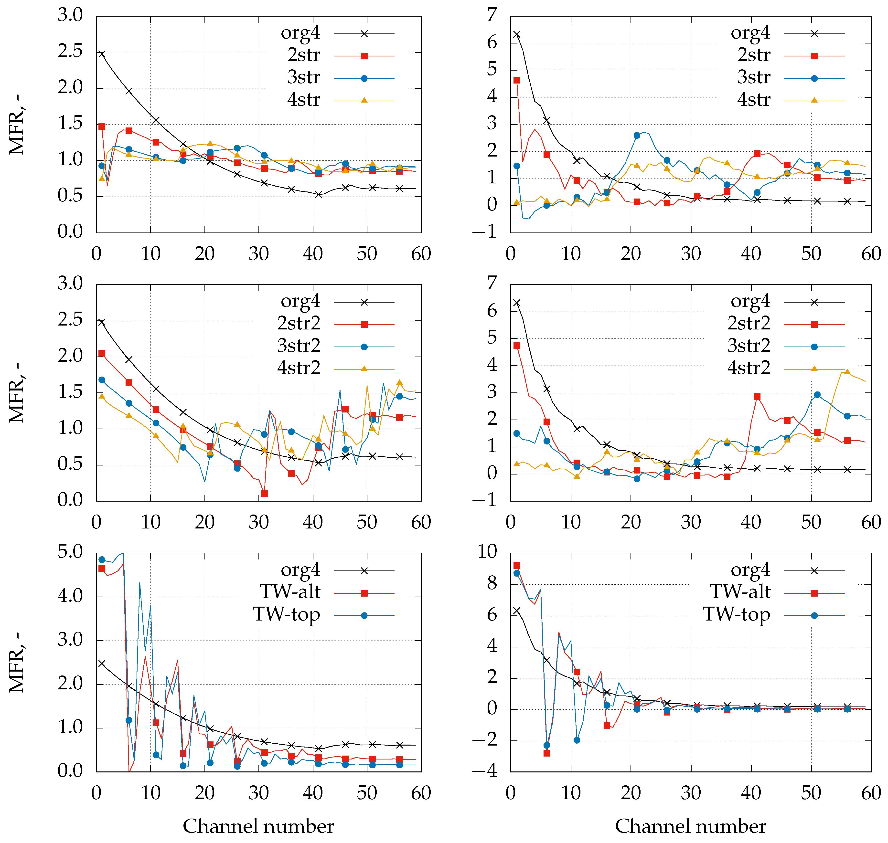
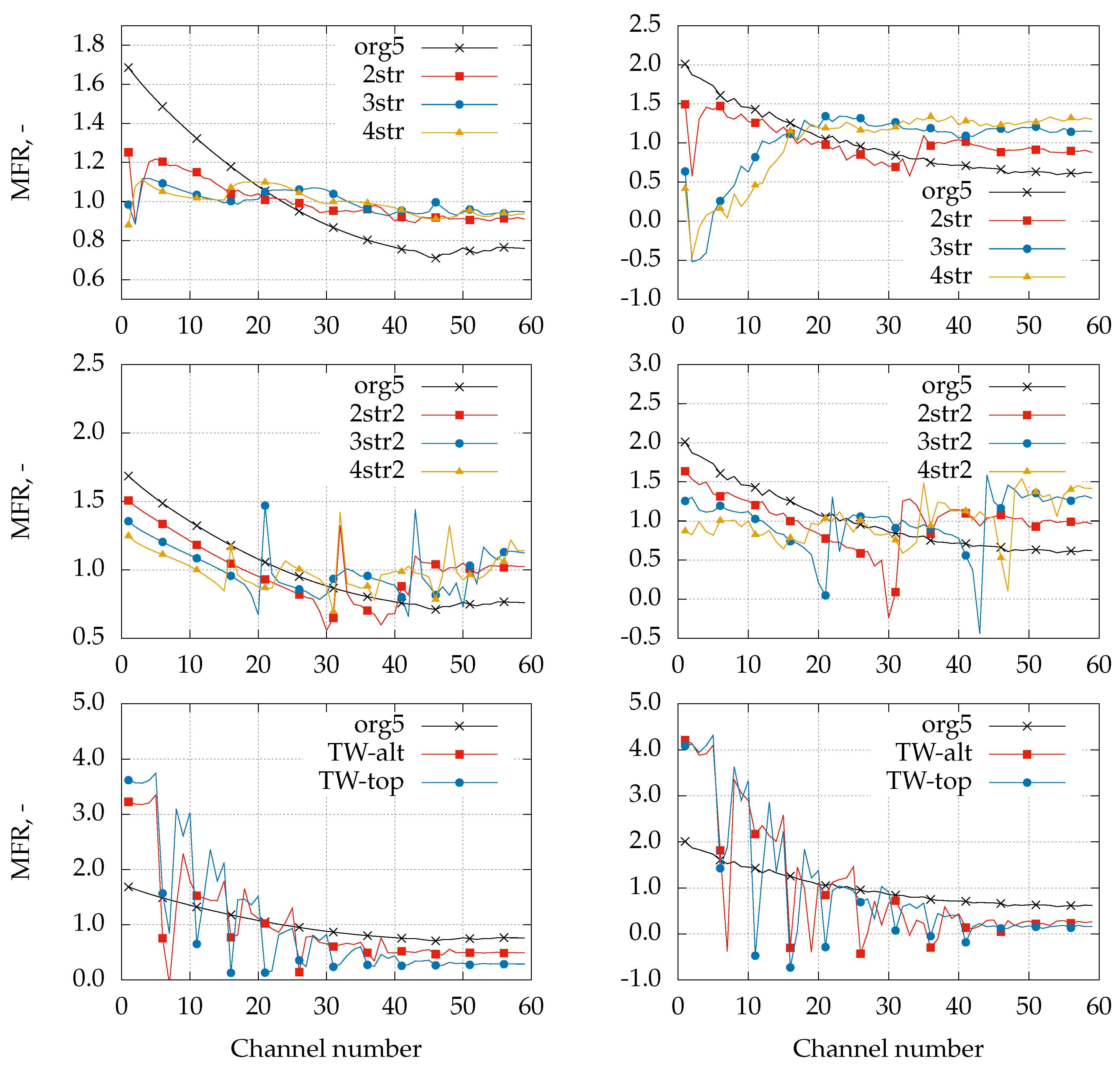
5.2. Effect of the Proposed Geometrical Modifications to the PHE on Flow Maldistribution
Figure 6, Figure 7 and Figure 8, and Table 8, Table 9 and Table 10 summarize the results of the considered geometrical modifications for the cases org, org4, org5, respectively. The geometries of org and org4 serve as a reference for the results of the full 2D PHE model for org5. Thanks to this, the influence of throttling and mixing baffles can be studied separately. Solutions containing additional horizontal baffles are observed to reduce the flow maldistribution significantly for the whole range of the considered . It is not obvious what number of dividers is most preferable, but cases with a lower number of horizontal dividers tend to have more optimal outcomes. This is especially visible in the case of org5, which represents the full 2D model of the PHE. The lower value for a larger number of dividers can be related to the alternating levels of pressure balance in the PHE. Every additional divider creates a smaller hydraulic diameter in the lower collector pipe and, consequently, a larger pressure drop in the PHE header.
Opposite to this, in the case of vertical baffles (TW-top and TW-alt), the flow maldistribution becomes even greater when compared to the unmodified geometry of org5. The vertical obstacles create more turbulence in the header and the overall performance of the PHE seems to be less stable. Consequently, this also causes a higher pressure drop in the PHE header and enhances the tendency of the flow to choose ”the easiest way” through the first few channels.
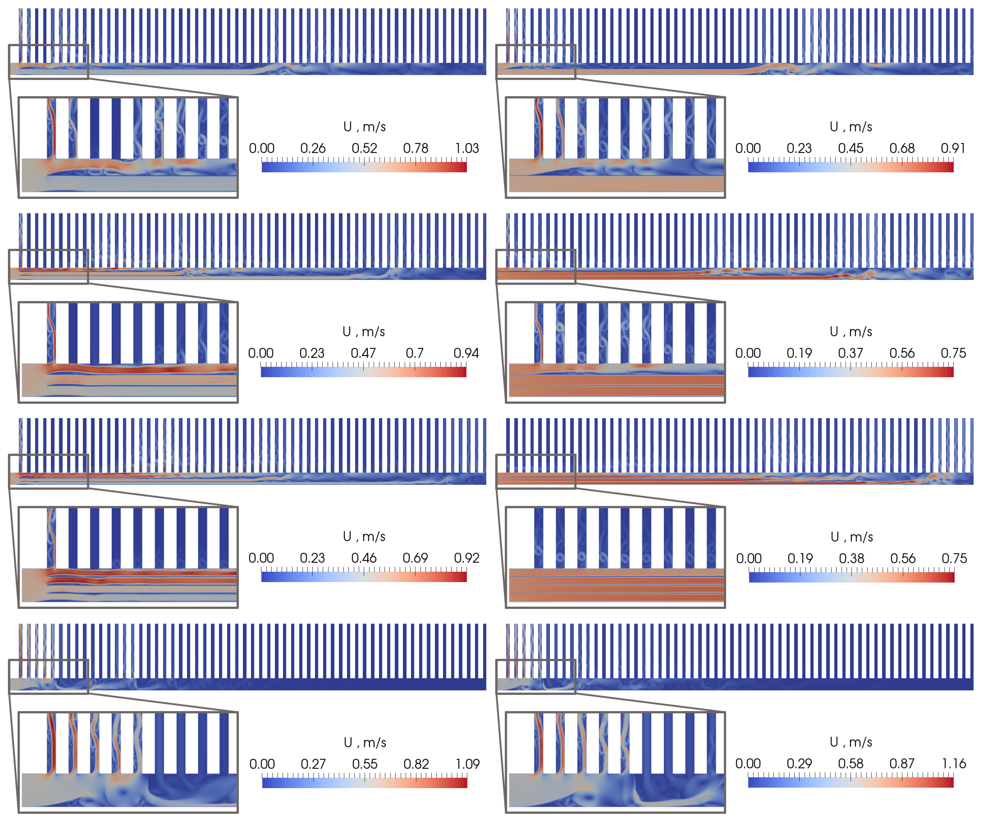
Figure 9 visualizes the flow in the PHE for using the velocity magnitude. The magnified regions show the detailed influence of the particular solution on the flow in the bottom collector and in the vicinity of the PHE inlet. The horizontal dividers are observed to provide fluid to the farther regions of the PHE. Moreover, no back flow at the end of any horizontal divider is visible.
In the case of vertical baffles, the flow is significantly blocked by the first baffle, which results in very similar PHE performance for both considered solutions with vertical baffles, compared with the last row in Figure 8.
6. Conclusions
The presented work is focused on developing an efficient and fast numerical methodology for comprehensive research related to PHEs. The robust transformation of the real 3D geometry of a PHE into a 2D representation was a key feature in order to significantly reduce the time for computation, as well as to provide trustworthy results. The proposed geometrical transformation reduced the number of computational mesh cells by two orders of magnitude. A key feature of the 2D transformation was the introduction of mixing and throttling baffles. The number and placement of the mixing baffles were directly related to the original 3D geometry and their task was to mimic a wavy flow pattern caused by the chevron pattern. The necessity of the throttling baffles was justified to assure the same pressure balance between the 3D and 2D geometries. Their size was calculated based on the assumption that a cumulative pressure drop should be preserved between the original 3D geometry and its 2D representation.
The developed 2D model made it possible to perform a significant number of calculations, and to explore a wide range of parameter space, (50, 100, 250, 500, 1000), and a number of various geometrical modifications introduced to the PHE. The main idea of the proposed geometrical changes was to assure its simplicity and ease of production. Consequently, a number of cases introducing additional horizontal and vertical dividers to the header of the PHE (bottom collector pipe) was considered. An analysis of the results provided a potentially meaningful insight into more preferable geometrical modifications leading to a more uniform flow distribution in the PHE channels.
In the case of a typical PHE, a reasonable solution is to introduce horizontal dividers to its bottom collector. This divides the inlet flow into several streams and directly delivers it into farther sections of the PHE. More optimal solutions are with a smaller number of horizontal dividers. Every additional divider creates a smaller hydraulic diameter and, consequently, a larger pressure drop in the PHE header. In the case of introducing vertical baffles to the PHE header, flow maldistribution becomes even greater than with a PHE without any baffles. The vertical obstacles intensify the turbulence and the overall performance of the PHE seems to be less stable. Consequently, this causes a higher pressure drop in the PHE header too. The above conclusions should also hold in the case of two-phase flows or flows with a phase change.
The proposed methodology of the 2D transformation can be potentially seen as universal. It should be possible to adopt the developed methodology to different types of PHE. Different perforation patterns of the PHE plates could be potentially modeled with different distribution, sizes and angles of mixing baffles. In general, they should mimic the original plate pattern ”as closely as possible”. In the case of a lower Reynolds numbers, this should provide trustworthy results because the flow in a real PHE is approximately two-dimensional. In the author’s previous work [19] the flow in-between the plates was shown to remain two-dimensional up to a channel Reynolds number of 250 for V-chevron plates. Consequently, the main limitation of the proposed 2D methodology can be disclosed in the case of a higher Reynolds numbers, because the flow in a real PHE would become fully three-dimensional. Assuming that a flow with a higher Reynolds number would mostly influence the overall pressure balance in the PHE, the 2D model can be adjusted to the 3D original by assuring the same pressure balance. This can be achieved using a similar methodology to the one presented in this work. It would require full 3D calculations, but only for one flow channel (single pair of plates).
It is worth noting that the proposed methodology is purely geometrical and independent from a mathematical model. It is ready to be used for a multi-phase flow or a flow with a phase change. In such cases, the size of the throttling baffles should be determined using an adequate flow model, but the general methodology would be similar to the one presented in the current studies.
Author Contributions
Original draft preparation Z.M. and A.B.; supervision Z.M.; conceptualization, A.B. and Z.M.; methodology, A.B., Z.M. and P.P; writing—review and editing, Z.M.; visualization, A.B. and P.P; numerical simulations, A.B. and P.P.
Funding
The presented work has been undertaken in the framework of the Poland – Taiwan scientific cooperation, as a part of the project “Development of plate heat exchangers for liquid inert gas vaporization, and the modelling of the two-phase flow in heat exchangers” (PHEVAP), financed by The National Center for Research and Development, Poland, No. PL-TWIII/7/2016. The work has been partly supported by statutory funds from Polish Ministry for Science and Higher Education No. 0401/0168/17.
Acknowledgments
Calculations have been carried out using resources provided by Wroclaw Centre for Networking and Supercomputing (http://wcss.pl), grant No. 460. The authors would like to thank Chia-Luen Lee for her careful proofreading and language corrections.
Conflicts of Interest
The authors declare no conflict of interest.
Nomenclature
| A | cross-section |
| D | hydraulic diameter |
| degree of maldistribution | |
| H | height of rectangular 2D PHE collector pipe |
| h | size of throttling baffle in mm |
| size of throttling baffle in % | |
| K | linear pressure loss coefficient |
| L | length of PHE collector pipe |
| m | mass flow |
| mass flow ratio coefficient | |
| N | number of PHE channels |
| p | pressure |
| pressure drop | |
| Reynolds number | |
| s | average absolute deviation |
| velocity vector | |
| average velocity | |
| W | width of PHE channel |
| local pressure loss coefficient | |
| friction factor | |
| dynamic viscosity | |
| effective kinematic viscosity | |
| density | |
| subscripts | |
| average | |
| refers to baffle | |
| c | channel |
| extra/additional | |
| h | header |
| i | numbering index |
| inlet | |
| h | header |
| outlet | |
| w | the worst case |
| y | vertical coordinate |
| superscripts | |
| two-dimensional | |
| three-dimensional |
References
- Mueller, A.C.; Chiou, J.P. Review of various Types of Flow Maldistribution in Heat Exchangers. Heat Transfer Eng. 1988, 9, 36–50. [Google Scholar] [CrossRef]
- Pacio, J.C.; Dorao, C.A. A study of the effect of flow maldistribution on heat transfer performance in evaporators. Nucl. Eng. Des. 2010, 240, 3868–3877. [Google Scholar] [CrossRef]
- Chowdhury, K.; Sarangi, S. Effect of Flow Maldistribution on Multipassage Heat Exchanger Performance. Heat Transfer Eng. 1985, 6, 45–54. [Google Scholar] [CrossRef]
- Fleming, R.B. The Effect of Flow Distribution in Parallel Channels of Counterflow Heat Exchangers. In Advances in Cryogenic Engineering; Timmerhaus, K.D., Ed.; Springer: Boston, MA, USA, 1967; pp. 352–362. [Google Scholar]
- Jung, J.; Jeong, S. Effect of flow mal-distribution on effective NTU in multi-channel counter-flow heat exchanger of single body. Cryogenics 2007, 47, 232–242. [Google Scholar] [CrossRef]
- Pawar, N.; Maurya, R.S. Flow maldistribution in a simplified plate heat exchanger model-A numerical study. Appl. Mech. Mater. 2012, 110, 2529–2536. [Google Scholar] [CrossRef]
- Wang, Z.Z.; Zhao, Z.N. Analysis of Performance of Steam Condensation Heat Transfer and Pressure Drop in Plate Condensers. Heat Transfer Eng. 1993, 14, 32–41. [Google Scholar] [CrossRef]
- Wang, L.; Christensen, R.; Sunden, B. An experimental investigation of steam condensation in plate heat exchangers. Int. J. Heat Exch. 2000, 1, 125–150. [Google Scholar]
- Bobbili, P.R.; Sunden, B. Steam Condensation in Parallel Channels of Plate Heat Exchangers. In Proceedings of the ASME International Mechanical Engineering Congress and Exposition, Volume 7: Fluid Flow, Heat Transfer and Thermal Systems, Parts A and B, Vancouver, BC, Canada, 12–18 November 2010; pp. 851–857. [Google Scholar] [CrossRef]
- Vist, S.; Pettersen, J. Two-phase flow distribution in compact heat exchanger manifolds. Exp. Therm. Fluid Sci. 2004, 28, 209–215. [Google Scholar] [CrossRef]
- Sterner, D.; Sunden, B. Performance of Plate Heat Exchangers for Evaporation of Ammonia. Heat Transfer Eng. 2006, 27, 45–55. [Google Scholar] [CrossRef]
- Lin, Y.H.; Li, G.C.; Yang, C.Y. An experimental observation of the effect of flow direction for evaporation heat transfer in plate heat exchanger. Appl. Therm. Eng. 2015, 88, 425–432. [Google Scholar] [CrossRef]
- Jensen, J.K.; Kaernl, M.R.; Ommen, T.S.; Brix, W.; Reinholdt, L.; Elmeegard, B. Effect of liquid/vapour maldistribution on the performance of plate heat exchanger evaporators. In Proceedings of the 24th IIR International Congress of Refrigeration, Yokohama, Japan, 16–22 August 2015. [Google Scholar]
- Wen, J.; Li, Y.; Wang, S.; Zhou, A. Experimental investigation of header configuration improvement in plate–fin heat exchanger. Appl. Therm. Eng. 2007, 27, 1761–1770. [Google Scholar] [CrossRef]
- Raul, A.; Bhasme, B.; Maurya, R. A Numerical Investigation of Fluid Flow Maldistribution in Inlet Header Configuration of Plate Fin Heat Exchanger. Energy Procedia 2016, 90, 267–275. [Google Scholar] [CrossRef]
- Peng, X.; Liu, Z.; Qiu, C.; Tan, J. Effect of inlet flow maldistribution on the passage arrangement design of multi-stream plate-fin heat exchanger. Appl. Therm. Eng. 2016, 103, 67–76. [Google Scholar] [CrossRef]
- Yuan, P.; Jiang, G.; He, Y.; Yi, X.; Tao, W. Experimental study on the performance of a novel structure for two-phase flow distribution in parallel vertical channels. Int. J. Multiphase Flow 2013, 53, 65–74. [Google Scholar] [CrossRef]
- Srihari, N.; Rao, B.P.; Sunden, B.; Das, S.K. Transient response of plate heat exchangers considering effect of flow maldistribution. Int. J. Heat Mass Transfer 2005, 48, 3231–3243. [Google Scholar] [CrossRef]
- Malecha, Z.; Płuszka, P.; Brenk, A. Numerical investigation of cryogen re-gasification in a plate heat exchanger. IOP Conf. Ser. Mater. Sci. Eng. 2017, 278, 012063. [Google Scholar] [CrossRef] [Green Version]
- Wang, Y.N.; Lee, J.P.; Park, M.H.; Jin, B.J.; Yun, T.J.; Song, Y.H.; Kim, I.S. A Study on 3D Numerical Model for Plate Heat Exchanger. Procedia Eng. 2017, 174, 188–194. [Google Scholar] [CrossRef]
- Tamakuwala, H.; Von Ness, R.; Banerjee, D. Numerical Modeling of Chevron Plate Heat Exchangers for Thermal Management Applications. In Proceedings of the ASME Heat Transfer Summer Conference, Volume 1: Heat Transfer in Energy Systems, Washington, DC, USA, 10–14 July 2016. [Google Scholar] [CrossRef]
- Wang, P.; Li, D.; Huang, Y.; Zheng, X.; Wang, Y.; Peng, Z.; Ding, Y. Numerical Study of Solidification in a Plate Heat Exchange Device with a Zigzag Configuration Containing Multiple Phase-Change-Materials. Energies 2016, 9, 394. [Google Scholar] [CrossRef]
- Weller, H.G.; Tabor, G.; Jasak, H.; Fureby, C. A Tensorial Approach to Computational Continuum Mechanics Using Object-oriented Techniques. Comput. Phys. 1998, 12, 620–631. [Google Scholar] [CrossRef]
- The Open Source CFD Toolbox User Guide. 2017. Available online: https://openfoam.org (accessed on 26 July 2017).
- Bozza, G.; Malecha, Z.M.; Weelderen, R.V. Development and application of a generic {CFD} toolkit covering the heat flows in combined solid–liquid systems with emphasis on the thermal design of HiLumi superconducting magnets. Cryogenics 2016, 80, 253–264. [Google Scholar] [CrossRef]
- Malecha, Z.M.; Jedrusyna, A.; Grabowski, M.; Chorowski, M.; van Weelderen, R. Experimental and numerical investigation of the emergency helium release into the LHC tunnel. Cryogenics 2016, 80, 17–32. [Google Scholar] [CrossRef]
- Chini, G.; Malecha, Z.; Dreeben, T. Large-amplitude acoustic streaming. J. Fluid Mech. 2014, 744, 329–351. [Google Scholar] [CrossRef]
- Batchelor, G.K. An Introduction to Fluid Dynamics; Cambridge University Press: Cambridge, UK, 2000. [Google Scholar]
- White, F.M. Fluid Mechanics, 4th ed.; McGraw-Hill: New York, NY, USA, 2014. [Google Scholar]
Figure 1.
Comparison of real 3D PHE geometry and its 2D representation. For better visibility only a single pair of plates is shown. In the current studies a PHE assembled from 60 plates is considered. Substantial changes in the inlet and outlet headers geometry (collector pipes) and a lack of a chevron pattern in the 2D geometry can be observed.

Figure 2.
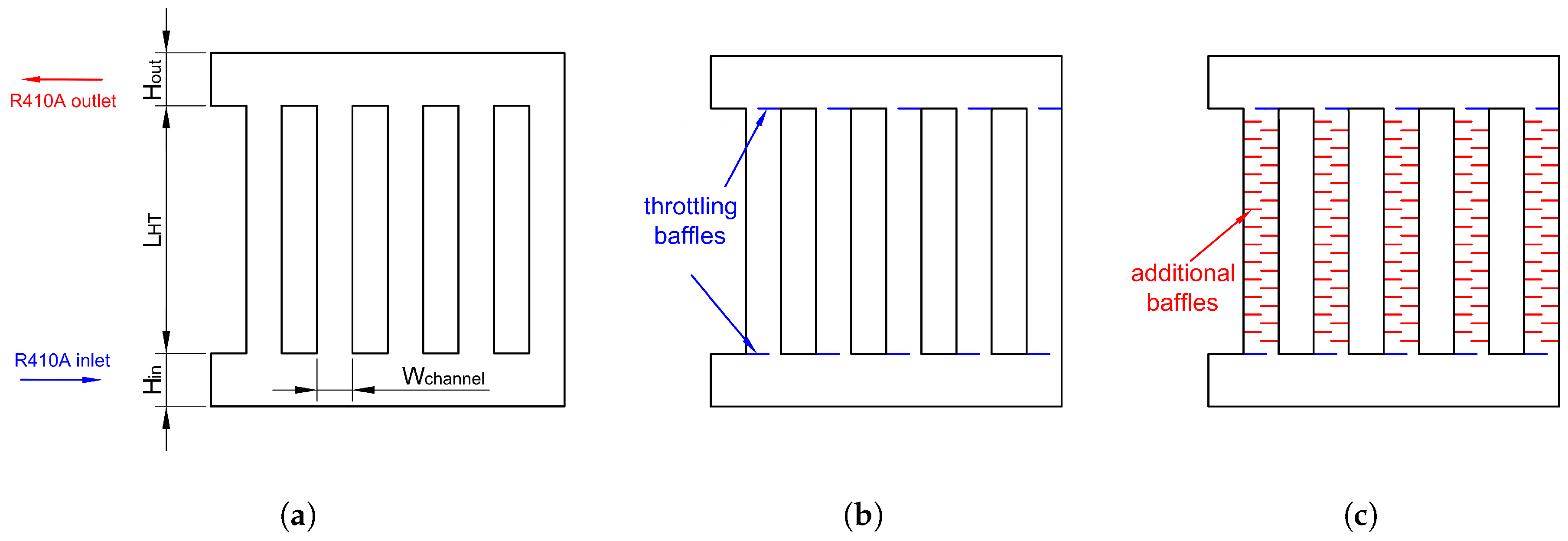
Sketch of the considered 2D model of PHE with additional geometrical modifications to assure similarity to the 3D geometry: (a) basic dimensions of 2D PHE; (b) placement of throttling baffles to preserve pressure balance between 2D and 3D geometries (blue); (c) mixing baffles to model the complexity of the 3D flow (red).
Figure 2.
Sketch of the considered 2D model of PHE with additional geometrical modifications to assure similarity to the 3D geometry: (a) basic dimensions of 2D PHE; (b) placement of throttling baffles to preserve pressure balance between 2D and 3D geometries (blue); (c) mixing baffles to model the complexity of the 3D flow (red).

Figure 3.
Views of circular and rectangular inlet/outlet channels used for numerical estimation of local loss coefficients by means of 3D incompressible calculations. Blue surfaces mark the measurement cross-sections. (a) Inlet 3D; (b) Outlet 3D; (c) Inlet 2D; (d) Outlet 2D.
Figure 3.
Views of circular and rectangular inlet/outlet channels used for numerical estimation of local loss coefficients by means of 3D incompressible calculations. Blue surfaces mark the measurement cross-sections. (a) Inlet 3D; (b) Outlet 3D; (c) Inlet 2D; (d) Outlet 2D.

Figure 4.
Schemes of the examined geometrical modifications. From left to right: 2str, 2str2, 3str, 3st2, 4str, 4str2, TW-top, TW-alt geometries, for a detailed explanation, see Table 6.
Figure 4.
Schemes of the examined geometrical modifications. From left to right: 2str, 2str2, 3str, 3st2, 4str, 4str2, TW-top, TW-alt geometries, for a detailed explanation, see Table 6.

Figure 5.
Change of MFR in the succeeding channels of PHE for different . From left to right: results for the org, org4 and org5 geometries.
Figure 5.
Change of MFR in the succeeding channels of PHE for different . From left to right: results for the org, org4 and org5 geometries.

Figure 6.
Flow maldistributions for the examined geometrical modifications for the org geometry and for 50 (left side) and 1000 (right side).
Figure 6.
Flow maldistributions for the examined geometrical modifications for the org geometry and for 50 (left side) and 1000 (right side).

Figure 7.
Flow maldistribution for the examined geometrical modifications for org4 geometry and for 50 (left side) and 1000 (right side).
Figure 7.
Flow maldistribution for the examined geometrical modifications for org4 geometry and for 50 (left side) and 1000 (right side).

Figure 8.
Flow maldistribution for the examined geometrical modifications for org5 geometry and for 50 (left side) and 1000 (right side).
Figure 8.
Flow maldistribution for the examined geometrical modifications for org5 geometry and for 50 (left side) and 1000 (right side).

Figure 9.
View of the velocity field magnitude for . From left to right: 2str, 2str2, 3str, 3st2, 4str, 4str2, TW-top, TW-alt geometries.
Figure 9.
View of the velocity field magnitude for . From left to right: 2str, 2str2, 3str, 3st2, 4str, 4str2, TW-top, TW-alt geometries.


Table 1.
PHE dimensions used as reference [12].
Table 1.
PHE dimensions used as reference [12].
| Dimension | Value |
|---|---|
| Plate length | 300 mm |
| Plate width | 102 mm |
| Longitudinal distance between the stream ports | 250 mm |
| Plate thickness | 0.4 mm |
| Amplitude of the chevron passage | 2 mm |
| Wave length | 7 mm |
| Chevron angle | 65deg |
| Hydraulic diameter of the chevron passage () | 4 mm |
| Heat transfer area (plate projection, double sides) | 0.051 m |
| Cross-section area of the single passage () | 0.000204 m |
Table 2.
Local loss coefficients at the channel inlet and outlet for 3D and 2D geometries, compared with Figure 3.
Table 2.
Local loss coefficients at the channel inlet and outlet for 3D and 2D geometries, compared with Figure 3.
| Loss Coefficients | |||||
|---|---|---|---|---|---|
| 50 | 100 | 250 | 500 | 1000 | |
| 19.60 | 10.67 | 5.488 | 4.143 | 3.730 | |
| 39.16 | 21.29 | 10.70 | 7.044 | 6.756 | |
| 7.230 | 4.056 | 2.182 | 1.595 | 1.363 | |
| 21.12 | 11.46 | 6.032 | 4.172 | 3.595 | |
Table 3.
Values of the local loss coefficients in the function of the channel inlet opening () for different numbers.
Table 3.
Values of the local loss coefficients in the function of the channel inlet opening () for different numbers.
| 50 | 100 | 250 | 500 | 1000 | |
|---|---|---|---|---|---|
| 0 | 0 | 0 | 0 | 0 | 0 |
| 10 | 0.280 | 0.252 | 0.261 | 0.309 | 0.465 |
| 20 | 0.784 | 0.689 | 0.683 | 0.810 | 1.326 |
| 30 | 1.608 | 1.413 | 1.386 | 1.708 | 2.687 |
| 40 | 2.993 | 2.657 | 2.619 | 3.395 | 4.680 |
| 50 | 5.473 | 4.924 | 4.942 | 6.444 | 7.828 |
| 60 | 10.34 | 9.431 | 9.547 | 11.89 | 13.23 |
| 70 | 21.40 | 19.70 | 19.49 | 22.61 | 20.21 |
| 80 | 53.48 | 48.94 | 46.31 | 51.06 | 47.13 |
| 90 | 214.0 | 198.8 | 127.1 | 161.8 | 180.2 |
Table 4.
Values of the local loss coefficients in the function of the channel outlet opening () for different numbers.
Table 4.
Values of the local loss coefficients in the function of the channel outlet opening () for different numbers.
| 50 | 100 | 250 | 500 | 1000 | |
|---|---|---|---|---|---|
| 0 | 0 | 0 | 0 | 0 | 0 |
| 10 | 0.583 | 0.450 | 0.166 | 0.301 | 0.059 |
| 20 | 1.997 | 1.585 | 1.226 | 1.379 | 0.559 |
| 30 | 4.320 | 3.263 | 1.972 | 2.891 | 2.891 |
| 40 | 7.439 | 5.543 | 4.444 | 5.054 | 3.547 |
| 50 | 11.26 | 8.726 | 6.688 | 8.105 | 8.591 |
| 60 | 16.40 | 15.11 | 12.36 | 12.72 | 12.13 |
| 70 | 25.14 | 24.05 | 23.57 | 24.11 | 23.17 |
| 80 | 53.98 | 48.23 | 46.33 | 45.80 | 39.36 |
| 90 | 100.4 | 114.2 | 133.6 | 143.5 | 122.1 |
Table 5.
Sizes of the additional throttling baffles in mm, which need to be placed at every inlet and outlet of the PHE channels to preserve the same pressure loss balance between the original 3D geometry and its 2D representation.
Table 5.
Sizes of the additional throttling baffles in mm, which need to be placed at every inlet and outlet of the PHE channels to preserve the same pressure loss balance between the original 3D geometry and its 2D representation.
| Variable | |||||
|---|---|---|---|---|---|
| 50 | 100 | 250 | 500 | 1000 | |
| 11.5 | 6.13 | 2.95 | 2.25 | 2.11 | |
| mm | 1.22 | 1.05 | 0.83 | 0.66 | 0.52 |
| 17.1 | 9.34 | 4.31 | 2.57 | 2.91 | |
| mm | 1.22 | 1.02 | 0.79 | 0.61 | 0.60 |
Table 6.
Considered geometrical optimization and explanation of the abbreviations used in this work, see Figure 4.
Table 6.
Considered geometrical optimization and explanation of the abbreviations used in this work, see Figure 4.
| Geometry | Description |
|---|---|
| org | Basic 2D geometry of PHE without throttling and chevron baffles, Figure 2a. |
| org4 | Developed 2D geometry of PHE with throttling baffles added at channel inlet and outlet to assure the same pressure balance in 2D and 3D geometries, Figure 2b. |
| org5 | same as org4 but with mixing baffles added to every channel to mimic the wavy flow of the real 3D PHE, Figure 2c. |
| 2str | One horizontal baffle added to the bottom header of the PHE to improve flow distribution. The flow is divided into two streams. The baffles begin at the location of the first channel. |
| 3str | Two horizontal baffles added to the bottom header of the PHE to improve flow distribution. Flow is divided into three streams. The baffles begin at the location of the first channel. |
| 4str | Three horizontal baffles added to the bottom header of the PHE to improve flow distribution. Flow is divided into four streams. The baffles begin at the location of the first channel. |
| 2str2 | One horizontal baffle added to the bottom header of the PHE to improve flow distribution. Flow is divided into two streams. The baffles begin at the inlet to the PHE. |
| 3str2 | Two horizontal baffles added to the bottom header of the PHE to improve flow distribution. Flow is divided into three streams. The baffles begin at the inlet to the PHE. |
| 4str2 | Three horizontal baffles added to the bottom header of the PHE to improve flow distribution. Flow is divided into four streams. The baffles begin at the inlet to the PHE. |
| TW-top | Additional, vertical baffles introduced in the top part of the bottom header of the PHE. |
| TW-alt | Additional, vertical baffles introduced in the bottom header of the PHE, in a alternating top-bottom mode. |
Table 7.
Values of the DM coefficient for org, org4, and org5 geometries.
| Geometry | |||||
|---|---|---|---|---|---|
| 50 | 100 | 250 | 500 | 1000 | |
| org | 0.690 | 0.649 | 0.491 | 0.452 | 0.411 |
| org4 | 0.776 | 0.741 | 0.602 | 0.527 | 0.500 |
| org5 | 0.877 | 0.871 | 0.844 | 0.847 | 0.834 |
Table 8.
Values of the DM coefficients for the org geometry, Figure 2a.
Table 8.
Values of the DM coefficients for the org geometry, Figure 2a.
| Modification | |||||
|---|---|---|---|---|---|
| 50 | 100 | 250 | 500 | 1000 | |
| org | 0.690 | 0.649 | 0.491 | 0.452 | 0.411 |
| 2str | 0.818 | 0.750 | 0.599 | 0.481 | 0.552 |
| 3str | 0.909 | 0.881 | 0.753 | 0.662 | 0.604 |
| 4str | 0.893 | 0.866 | 0.766 | 0.699 | 0.689 |
| 2str2 | 0.776 | 0.683 | 0.593 | 0.452 | 0.456 |
| 3str2 | 0.792 | 0.696 | 0.604 | 0.523 | 0.527 |
| 4str2 | 0.830 | 0.760 | 0.662 | 0.612 | 0.597 |
| TW-alt | 0.495 | 0.377 | 0.237 | 0.199 | 0.141 |
| TW-top | 0.375 | 0.335 | 0.235 | 0.174 | 0.130 |
Table 9.
Values of the DM coefficient for the org4 geometry, Figure 2b.
Table 9.
Values of the DM coefficient for the org4 geometry, Figure 2b.
| Modification | |||||
|---|---|---|---|---|---|
| 50 | 100 | 250 | 500 | 1000 | |
| org4 | 0.776 | 0.741 | 0.602 | 0.527 | 0.500 |
| 2str | 0.920 | 0.855 | 0.765 | 0.631 | 0.692 |
| 3str | 0.948 | 0.923 | 0.820 | 0.767 | 0.700 |
| 4str | 0.952 | 0.912 | 0.805 | 0.774 | 0.758 |
| 2str2 | 0.809 | 0.761 | 0.616 | 0.543 | 0.526 |
| 3str2 | 0.859 | 0.780 | 0.712 | 0.601 | 0.633 |
| 4str2 | 0.884 | 0.813 | 0.702 | 0.675 | 0.655 |
| TW-alt | 0.561 | 0.405 | 0.341 | 0.232 | 0.207 |
| TW-top | 0.449 | 0.345 | 0.315 | 0.219 | 0.192 |
Table 10.
Values of the DM coefficients for org5 geometry, Figure 2c.
Table 10.
Values of the DM coefficients for org5 geometry, Figure 2c.
| Modification | |||||
|---|---|---|---|---|---|
| 50 | 100 | 250 | 500 | 1000 | |
| org5 | 0.877 | 0.871 | 0.844 | 0.847 | 0.834 |
| 2str | 0.958 | 0.939 | 0.933 | 0.928 | 0.915 |
| 3str | 0.975 | 0.955 | 0.896 | 0.880 | 0.854 |
| 4str | 0.973 | 0.935 | 0.859 | 0.830 | 0.817 |
| 2str2 | 0.913 | 0.925 | 0.905 | 0.885 | 0.890 |
| 3str2 | 0.927 | 0.908 | 0.893 | 0.873 | 0.872 |
| 4str2 | 0.950 | 0.899 | 0.862 | 0.854 | 0.895 |
| TW-alt | 0.697 | 0.627 | 0.591 | 0.547 | 0.480 |
| TW-top | 0.570 | 0.519 | 0.508 | 0.520 | 0.500 |
© 2018 by the authors. Licensee MDPI, Basel, Switzerland. This article is an open access article distributed under the terms and conditions of the Creative Commons Attribution (CC BY) license (http://creativecommons.org/licenses/by/4.0/).
Share and Cite
MDPI and ACS Style
Brenk, A.; Pluszka, P.; Malecha, Z. Numerical Study of Flow Maldistribution in Multi-Plate Heat Exchangers Based on Robust 2D Model. Energies 2018, 11, 3121. https://doi.org/10.3390/en11113121
AMA Style
Brenk A, Pluszka P, Malecha Z. Numerical Study of Flow Maldistribution in Multi-Plate Heat Exchangers Based on Robust 2D Model. Energies. 2018; 11(11):3121. https://doi.org/10.3390/en11113121
Chicago/Turabian StyleBrenk, Arkadiusz, Pawel Pluszka, and Ziemowit Malecha. 2018. "Numerical Study of Flow Maldistribution in Multi-Plate Heat Exchangers Based on Robust 2D Model" Energies 11, no. 11: 3121. https://doi.org/10.3390/en11113121
Note that from the first issue of 2016, this journal uses article numbers instead of page numbers. See further details here.