Cyclic CH4 Injection for Enhanced Oil Recovery in the Eagle Ford Shale Reservoirs

1
Beijing Key Laboratory of Unconventional Natural Gas Geology Evaluation and Development Engineering, China University of Geosciences (Beijing), Beijing 100083, China
2
College of Engineering, Peking University, Beijing 100871, China
3
Research Institute of Petroleum Exploration and Development, PetroChina, Beijing 100083, China
*
Author to whom correspondence should be addressed.
Energies 2018, 11(11), 3094; https://doi.org/10.3390/en11113094
Submission received: 24 October 2018
/
Revised: 6 November 2018
/
Accepted: 7 November 2018
/
Published: 9 November 2018
(This article belongs to the Special Issue Improved Reservoir Models and Production Forecasting Techniques for Multi-Stage Fractured Hydrocarbon Wells)
Abstract
:Gas injection is one of the most effective enhanced oil recovery methods for the unconventional reservoirs. Recently, CH4 has been widely used; however, few studies exist to accurately evaluate the cyclic CH4 injection considering molecular diffusion and nanopore effects. Additionally, the effects of operation parameters are still not systematically understood. Therefore, the objective of this work is to build an efficient numerical model to investigate the impacts of molecular diffusion, capillary pressure, and operation parameters. The confined phase behavior was incorporated in the model considering the critical property shifts and capillary pressure. Subsequently, we built a field-scale simulation model of the Eagle Ford shale reservoir. The fluid properties under different pore sizes were evaluated. Finally, a series of studies were conducted to examine the contributions of each key parameter on the well production. Results of sensitivity analysis indicate that the effect of confinement and molecular diffusion significantly influence CH4 injection effectiveness, followed by matrix permeability, injection rate, injection time, and number of cycles. Primary depletion period and soaking time are less noticeable for the well performance in the selected case. Considering the effect of confinement and molecular diffusion leads to the increase in the well performance during the CH4 injection process. This work, for the first time, evaluates the nanopore effects and molecular diffusion on the CH4 injection. It provides an efficient numerical method to predict the well production in the EOR process. Additionally, it presents useful insights into the prediction of cyclic CH4 injection effectiveness and helps operators to optimize the EOR process in the shale reservoirs.
1. Introduction
As reported, around 40% of the natural gas reserves are contained in the unconventional reservoirs all over the world [1]. The Eagle Ford shale is one of the productive oil shale reservoirs in the North America, which is located in the northwest of Texas. The main thickness of production varies from 50 to 300 feet [2,3]. The technologies of horizontal drilling and multistage hydraulic fracturing have attracted much attention, especially for the micro- and nano-pores in the unconventional reservoirs [4,5]. The combination of these technologies is extensively used to exploit the reserves in the tight and shale reservoirs [6,7]. However, Dejam et al. [8,9] pointed out that low permeability may increase the threshold pressure gradient, and large amount of oil still reserves in the formations, which requires gas injection for the production enhancement [10,11,12].
Due to the low permeability of shale rocks, waterflooding cannot perform as effective as that in the conventional resources. Hence, the attention has been attracted to gas injection in the unconventional reservoirs. Recent theoretical and experimental studies have shown that CH4 injection is more impressive than CO2 because it has high compressibility and the sources are rich [13,14]. Therefore, CH4 can take the place of CO2 in some situations. Alfarge et al. [15] pointed out that extending soaking period and increasing injection volume are benefit to improve the well production. Meng and Sheng [16] conducted the experiment of CH4 Huff-n-Puff injection in the core samples, confirming that condensate recovery increase by 6% in the Huff-n-Puff injection operation. However, most studies focus on the primary depletion production; the physical mechanisms on the effectiveness of cyclic CH4 injection are still limited.
Literatures have reported the evaluation of gas injection in shale oil reservoirs [15,17,18,19]. Sigmund et al. [20] and Brusilovsky [21] have conducted experiments in the porous media. They concluded that the phase behavior in the porous media deviates from the bulk phase. Recent studies have shown that nanopore confinement is an important factor since the nanopores cause high capillary pressure, affecting the properties of components as well as phase behavior further theoretically and experimentally [22,23,24,25]. Wang et al. [26] and Nojabaei et al. [23] modified the vapor-liquid phase equilibrium model based on Young-Laplace equation and Leverett J-function. They then incorporated the phase equilibrium model into the reservoir simulator to predict the well production in the tight oil reservoirs. Yang et al. [27] modified the Peng-Robison equation of state and introduced a new term representing the molecule-wall interaction. They reproduced the collected data with an overall error of 7.64% compared to the molecular simulation results. Nanofluidic devices were applied to investigate the nanopore effects. Luo et al. [28] and Alfi et al. [29] conducted the nanofluidic experiment and they all concluded that the bubble point shifts with the effect of confinement. Salahshoor et al. [1] reviewed the mathematical models and experimental studies to compare the phase behavior in conventional reservoirs and tiny pores.
Molecular diffusion is another key mechanism affecting the gas injection effectiveness. Yu et al. [30] has investigated that molecular diffusivity should be correctly included in the simulation model. In the process of CO2-CH4 displacement, diffusion is also an important mechanism [31]. Zhang et al. [32] compared the oil recovery of CO2-EOR process and concluded that considering molecular diffusion is beneficial to improve the oil recovery. However, these investigations only focus on the CO2 injection process; the impact on the CH4 injection was not well understood. Recent studies have concluded that the diffusion coefficient of CH4 is on the same order of CO2 [33,34]; hence, the effect of molecular diffusion needs to be well examined.
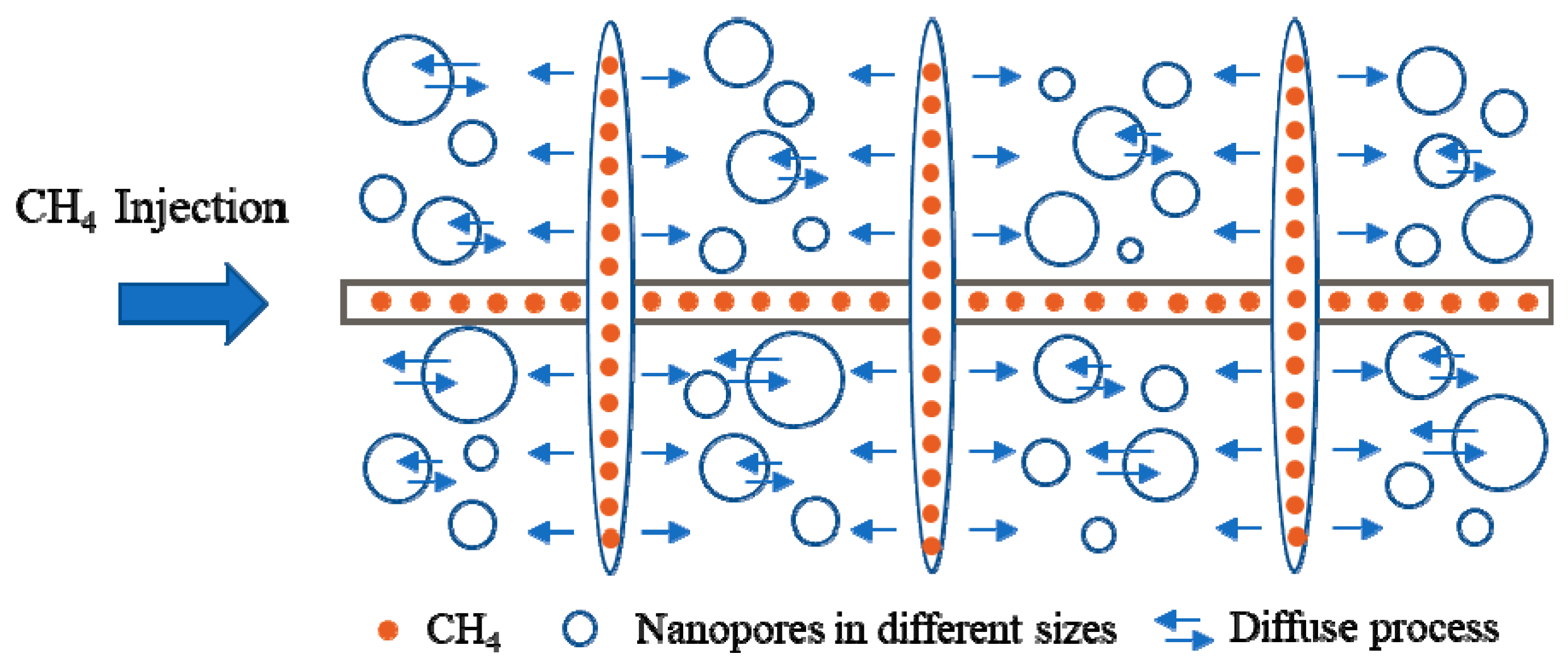
Figure 1 shows the sketch of CH4 injection process in the fractured horizontal well. As CH4 is injected, the molecules will move into the fractures and diffuse into the matrix. The fluid phase behavior in nanopores should be determined. Due to the nanopore effects, the injected components will not distribute homogenous among different sizes of pores. Additionally, it will result in different swelling effect in the gas injection from conventional reservoirs because of the confined phase behavior in nanopores.
From the literature survey, there are still some limitations behind the previous studies. Although the EOR process is efficient in the tight oil reservoirs, few studies focus on the effect of confinement on the EOR effectiveness, especially for the CH4 injection. Additionally, most of previous studies analyzed the operation parameters and the investigation of physical mechanisms affecting the CH4 injection is limited. In order to fill this gap, we proposed a useful method incorporating the phase behavior model into the compositional simulator, which can accurately and efficiently evaluate the effect of key parameters on the CH4 injection effectiveness. This work systematically analyzes the physical mechanisms and operation parameters; it can be easily used in the operations of EOR process.
In this work, we evaluated the effect of confinement and CH4 molecular diffusion on the cyclic CH4 injection in the Eagle Ford shale reservoir. First, the methodology and detailed procedure were explained. Then, we built a reservoir model based on the fluid properties from the published Eagle Ford data [35]. The pore size distribution was obtained from the Eagle Ford rock samples [24]. Afterwards, a series of sensitivity analysis were performed to identify the impacts of the physical mechanisms on the effectiveness of cyclic CH4 injection. Finally, we conducted the sensitivity analysis including operation parameters and physical mechanisms. This work provides a better analysis and optimization of CH4 injection in the Eagle Ford shale reservoir.
2. Methodology
2.1. Shifts of Critical Properties
The nanopore effect on the critical temperatures and pressures has been reported in the literatures [24,36,37]. The interaction between the molecules and the pore walls is significant when the pore size is less than 10 nm [38,39]. In our study, the correlations published by Singh et al. [36] were applied to describe the critical property shifts [40]:
where rp represents the pore-throat radius, and express the relative critical temperature and pressure shift, respectively. Tcb and Pcb are the bulk critical temperature and pressure, respectively. Tcp and Pcp are the critical temperature and critical pressure in the confined space, respectively. is the Lennard-Jones size parameter (collision diameter).
2.2. Phase Equilibrium Calculation Considering Nanopore Confinement
In order to include the effect of confinement in the phase equilibrium model, the criterion of phase equilibrium can be rewritten as:
where and express the fugacity of component i in the liquid and vapor phases, respectively. T is the reservoir temperature. PV and PL represent the pressures of the vapor and liquid phase, respectively. Pcap is the capillary pressure in the confined space, which is calculated using the Young-Laplace equation [41], defining as:
where represents the contact angle. In this model, the contact angle is assumed as zero and the angle between organic and inorganic pores was neglected. The interfacial tension, is calculated using the following equation:
where and denote density of the liquid and vapor phases, respectively. [P]i is the parachor of component i. Parachor of pure component and mixture can be obtained from the work by Pedersen and Christensen [42].
The Peng-Robinson equation of state [43] is modified as Equation (8) considering the effect of confinement:
where Vm and R represent the mole volume of component i and the universal gas constant, respectively. a and b are the parameters obtained by van der Waals mixing rules.
When the confinement is included, Equation (8) should be solved separately for liquid and vapor phases:
where , , , . ZL and ZV are the compressibility of liquid and vapor phases, respectively. The non-linear equations are solved by Newton-Raphson method. The roots of Equations (9) and (10) are determined with the criterion of Gibbs free energy minimization in the liquid and vapor phases.
In the following section, we first built a reservoir model based on the typical fluid and fracture properties, and then performed sensitivity analysis of different parameters in the cyclic CH4 injection. The fluid properties considering the nanopore effects were calculated through the phase equilibrium model. Afterwards, the properties were implemented into the reservoir simulator of CMG to evaluate the cyclic CH4 injection effectiveness [44]. The detailed workflow of this work is presented in Figure 2.
3. Base Case
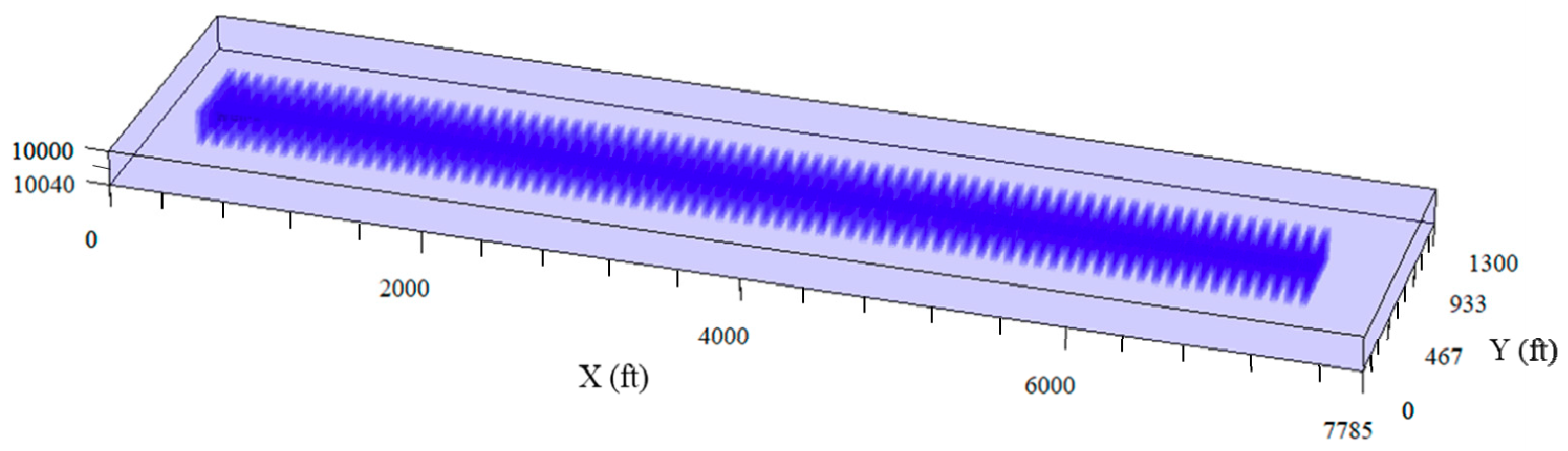
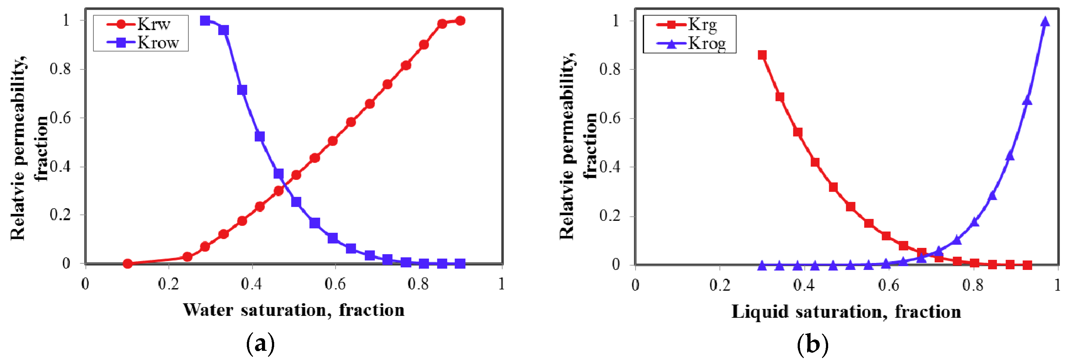
In the simulation study, we set up the reservoir model using the CMG-GEM simulator [44]. The domain of the model is: 7785 ft in x direction, 1300 ft in y direction, and 40 ft in z direction. A horizontal well was set in the middle of the reservoir model, along with 76 hydraulic fractures. The fracture spacing is 80 ft and the fracture half-length is 210 ft. As reported, the reservoir temperature is 270 °F, the matrix porosity is 12%, and the initial reservoir pressure is 8125 psi. Table 1 summarizes the reasonable rock and fluid properties in the Eagle Ford shale reservoir [45]. The reservoir model is shown in Figure 3. Mohebbinia and Wong [46] have pointed out that molecular diffusion would be dominated in the low-permeability fractured reservoirs when gravitational drainage is inefficient. Hence, only diffusion mechanism was included in this work. The relative permeability curves are shown in Figure 4.
In this study, the fluid in the Eagle Ford reservoir is assumed containing six pseudo-components. Properties and binary interaction coefficients are listed in Table 2 and Table 3, respectively. Oil gravity of 41 °API, gas-oil ratio of 1000 scf/stb, and formation volume factor of 1.65 rb/stb are obtained after tuning process. These properties have shown good agreements with the work by Orangi et al. [47].
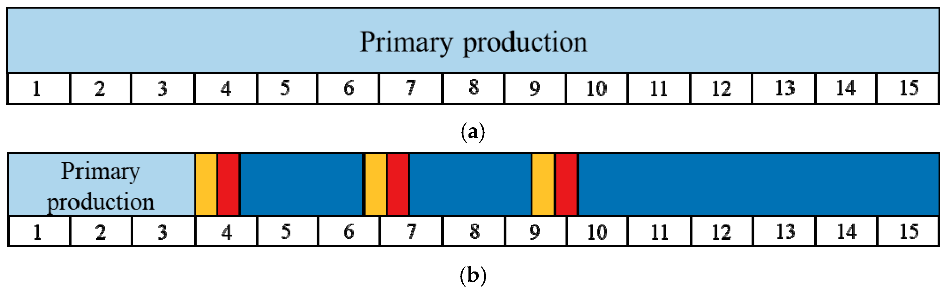
In the base case, BHP of 1800 psi is the constraint for the production well at the beginning of the simulations. In the first three years, the well experiences a depletion production period. After that, it will be transferred to an injection well. The injection rate of CH4 is set as 5000 Mscf/day. After 60 days of injection, the well will shut-in and begin a soaking period of 60 days. During the soaking period, the fluid is allowed to dissipate into the formation and mix with the fluid. Then the well is switched back on for another two-year production again. Thus, one cycle of CH4 injection is finished. In this model, the production well experiences three cycles and the total production time is 15 years, as shown in Figure 5. A series of cases were conducted to simulate the cyclic CH4 injection process. We compared the oil recovery factor in a 15-year period to investigate the effectiveness of CH4 injection in the following sections.
4. Results and Discussions
4.1. Effect of Confinement in Nanopores
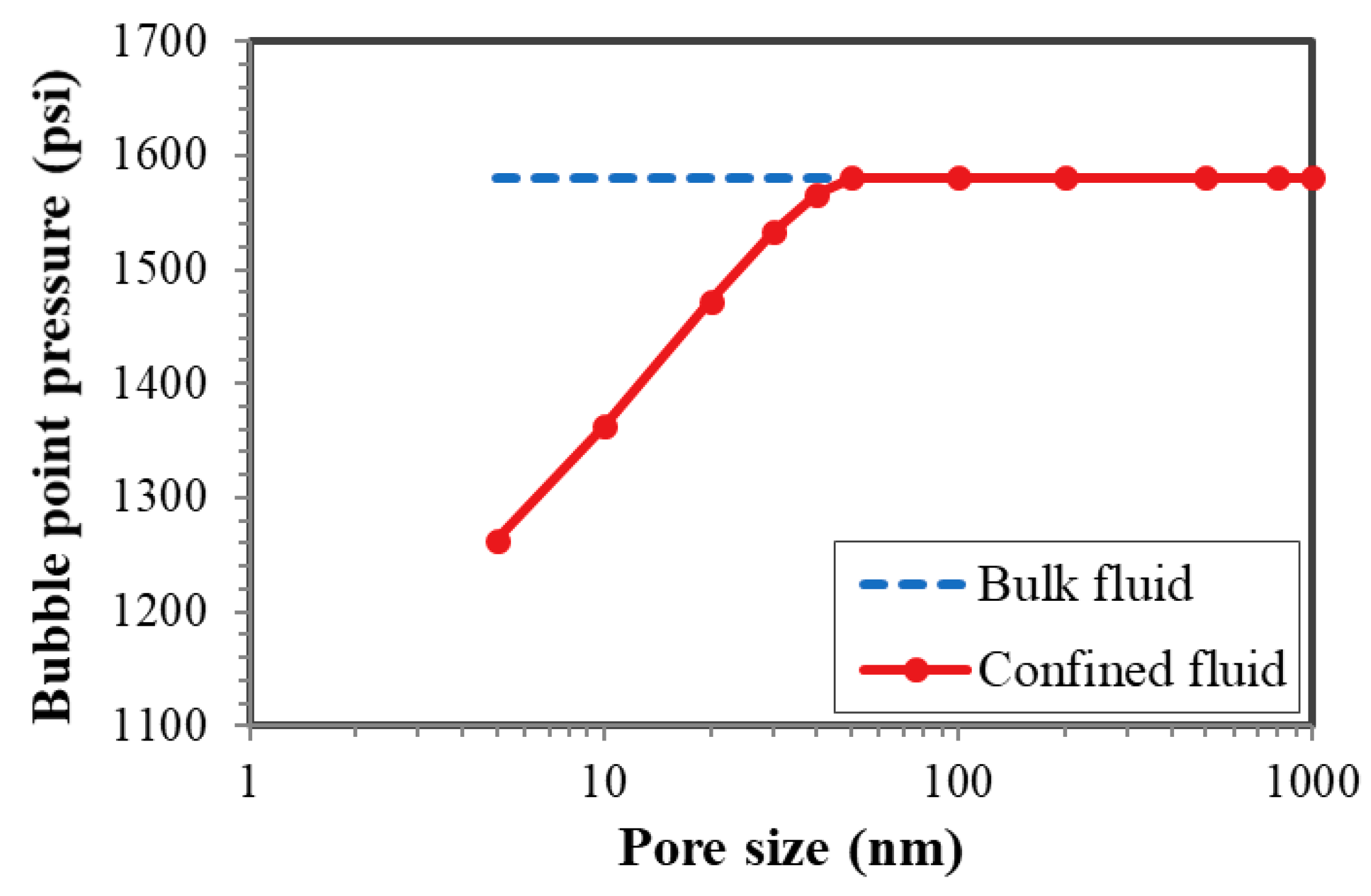
The confinement is significant in the low permeability formations due to the nanopores. According to the experiment data from the Eagle Ford core samples [24], around 80% of the pores are 20 nm or less. The fluid properties under 5 nm, 10 nm, and 15 nm were calculated using the Equations (1) through (3), respectively, as listed in Table 4. The results show that critical temperatures and pressures suppress as the pore sizes reduce. With the procedure in Figure 2, we calculated the phase equilibrium and obtained the bubble point pressure under different pore sizes. As shown in Figure 6, the bubble point pressure significantly decreases, especially for the small pores, which further impacts the oil recovery in the tight oil reservoirs.
Based on the pore size distribution of the formation, division of different pore regions are determined to represent the practical situation. Numbers of region ranging from 3 to 5 has been investigated and we finally decided 4 regions, which reduces computational cost and evaluates the confinement more reasonably. The contributions of each region are: less than 5 nm (42%), 5~10 nm (27%), 10~20 nm (13%), and larger than 20 nm (18%), respectively. The PVT properties of different pore sizes can be obtained in Section 2.1.
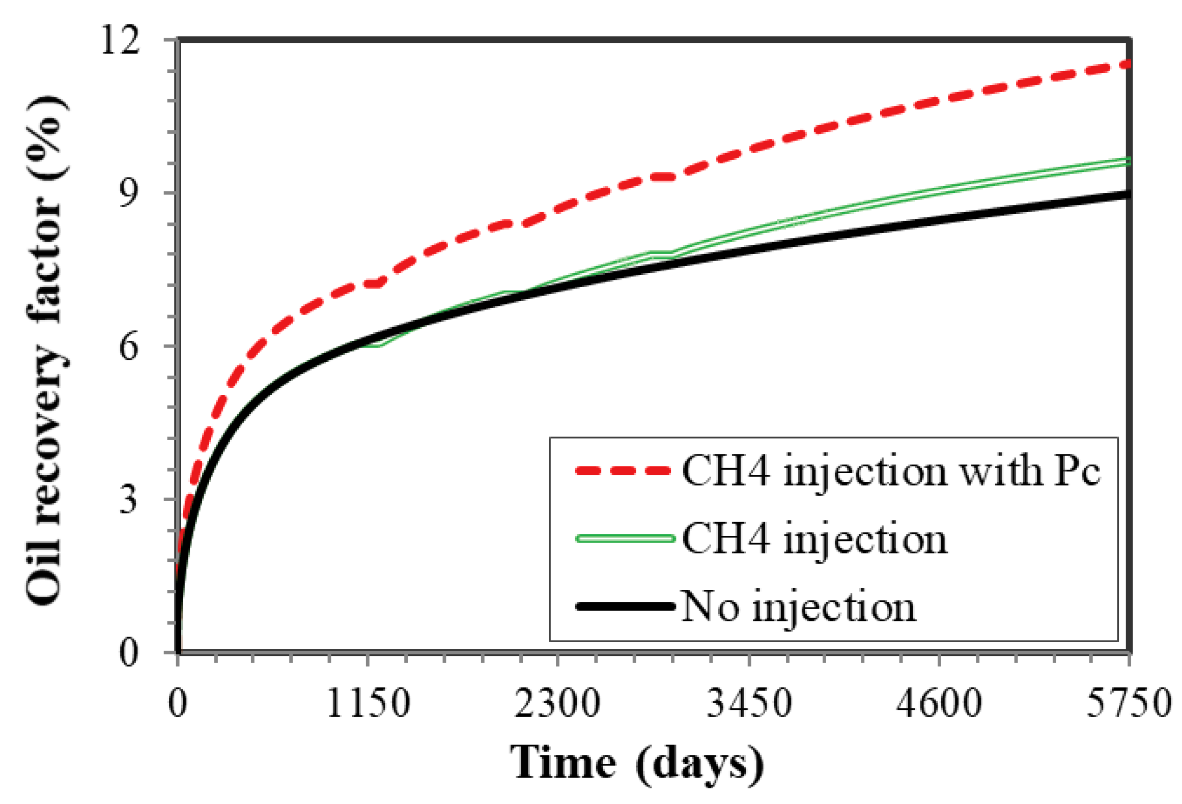
The effect of nanopore confinement on the well production was shown in Figure 7. It can be observed that the incremental oil recovery factor at the end of 15 years is 0.8% and 2.3% at the pore size of 10 nm and bulk, respectively, illustrating that the effect of confinement has a positive influence on the cyclic CH4 injection effectiveness. Due to the confinement, the miscibility minimum pressure of the mixture and the oil viscosity decrease, leading to the improvement of well performance. Additionally, the bubble point pressure in the confined space is lower than the bulk phase, meaning that a longer time of single-phase production exist during the production. Hence, the confinement should be correctly included in the analysis of gas injection in the shale reservoirs. All the following cases include the confinement.
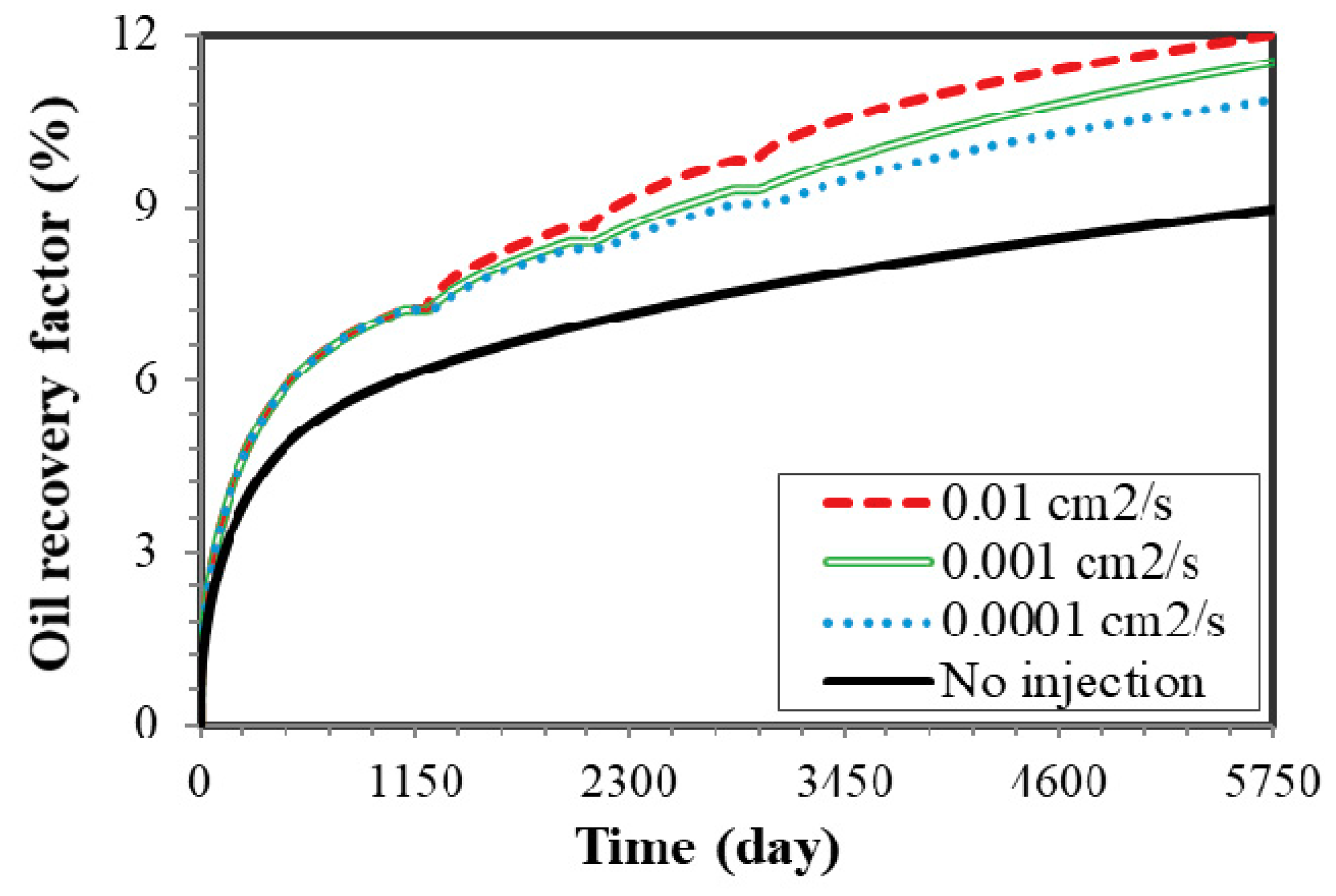
4.2. Molecular Diffusion
Molecular diffusion is another key parameter since CH4 can move into the formation and mix with the oil during the soaking time. Neglecting diffusion coefficient will underestimate the ultimate oil recovery. In order to better analyze the mechanism of diffusion, we compared the oil recovery after 15 years with the coefficient ranging from 0.0001 cm2/s to 0.01 cm2/s. As shown in Figure 8, the incremental oil recovery is 1.92%, 2.36%, and 2.98%, with the coefficients of 0.0001, 0.001, and 0.01 cm2/s, respectively. The results indicate that more CH4 molecules will diffuse into the matrix instead of concentrating around the fractures with larger diffusion coefficient. Hence, more oil will be swept, resulting in larger oil production.
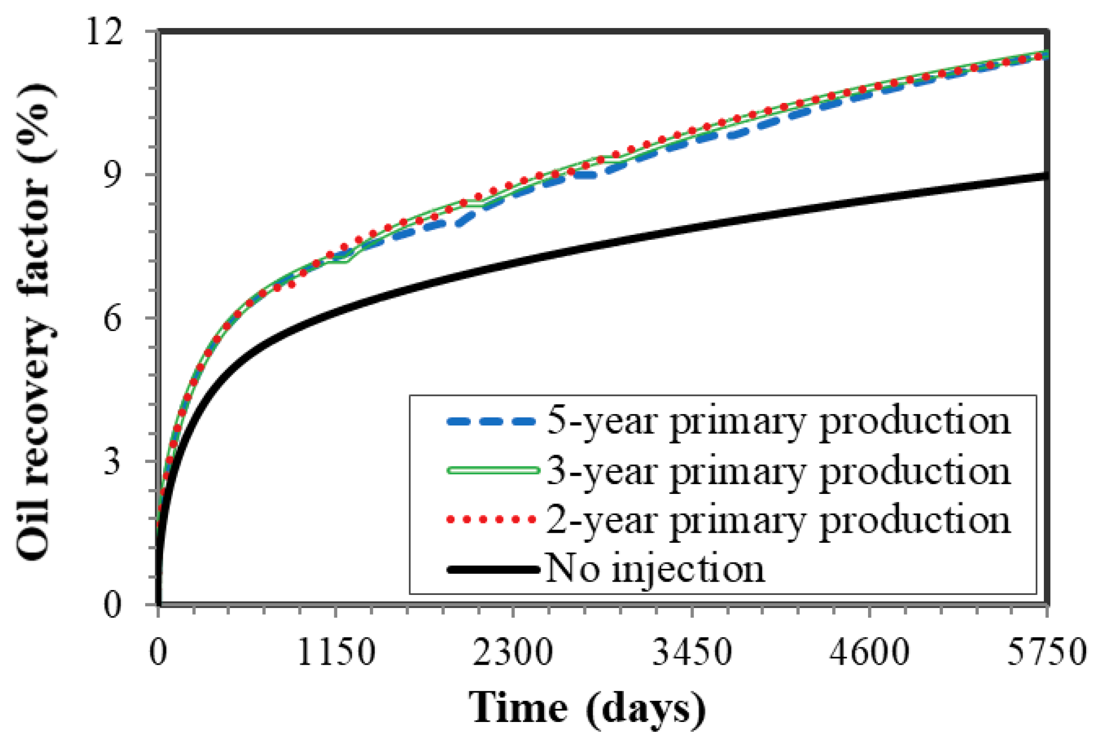
4.3. Effect of Primary Depletion Period
The length of primary depletion period of 2, 3, and 5 years was studied, while other parameters were kept the same as the base case. As presented in Figure 9, the impact of primary depletion period is not noticeable since the increment is 2.28%, 2.34%, and 2.41%, respectively in this case. Delaying the start of gas injection is beneficial to improve the well production. However, if it starts too late, the production will decrease. Hence, decision of suitable primary depletion period is essential for the operations of CH4 injection in the shale reservoirs.
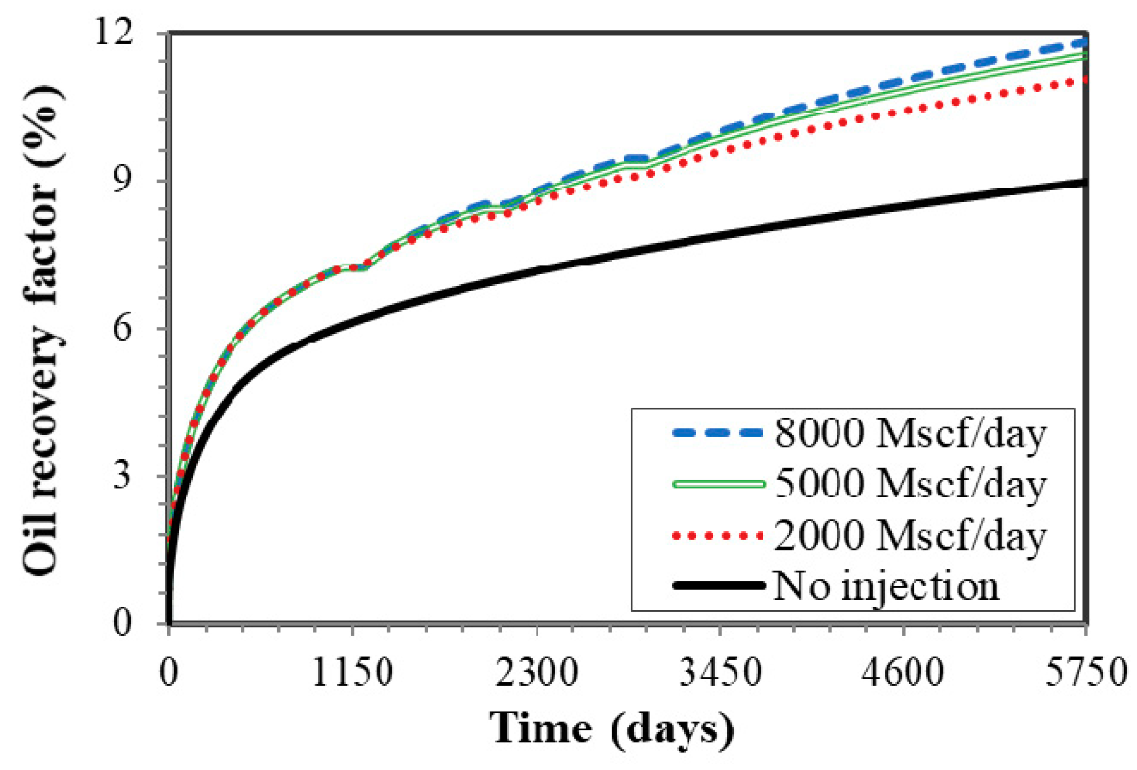
4.4. Effect of Injection Rate
Gas injection rate is directly related to the volume of CH4 injected. A series of cases were conducted to investigate the effect of injection rate on the well performance of cyclic CH4 injection. The rates were set as 2000, 5000, and 8000 Mscf/day, respectively. The results in Figure 10 show that the incremental oil recovery was 2.07%, 2.55%, and 2.82%, for the case of 2000, 5000, and 8000 Mscf/day, respectively, illustrating that higher injection rate leads to larger incremental oil recovery factor.
4.5. Effect of Injection Time
The length of injection time also impacts the CH4 injection volume. We analyzed three cases with the injection time varying from 1 month to 3 months and kept other parameters as the same in the base case. As shown in Figure 11, oil recovery factor increases by 2.20%, 2.55%, and 2.76%, respectively. The results illustrate that longer injection time is beneficial to improve the efficiency of cyclic gas injection.
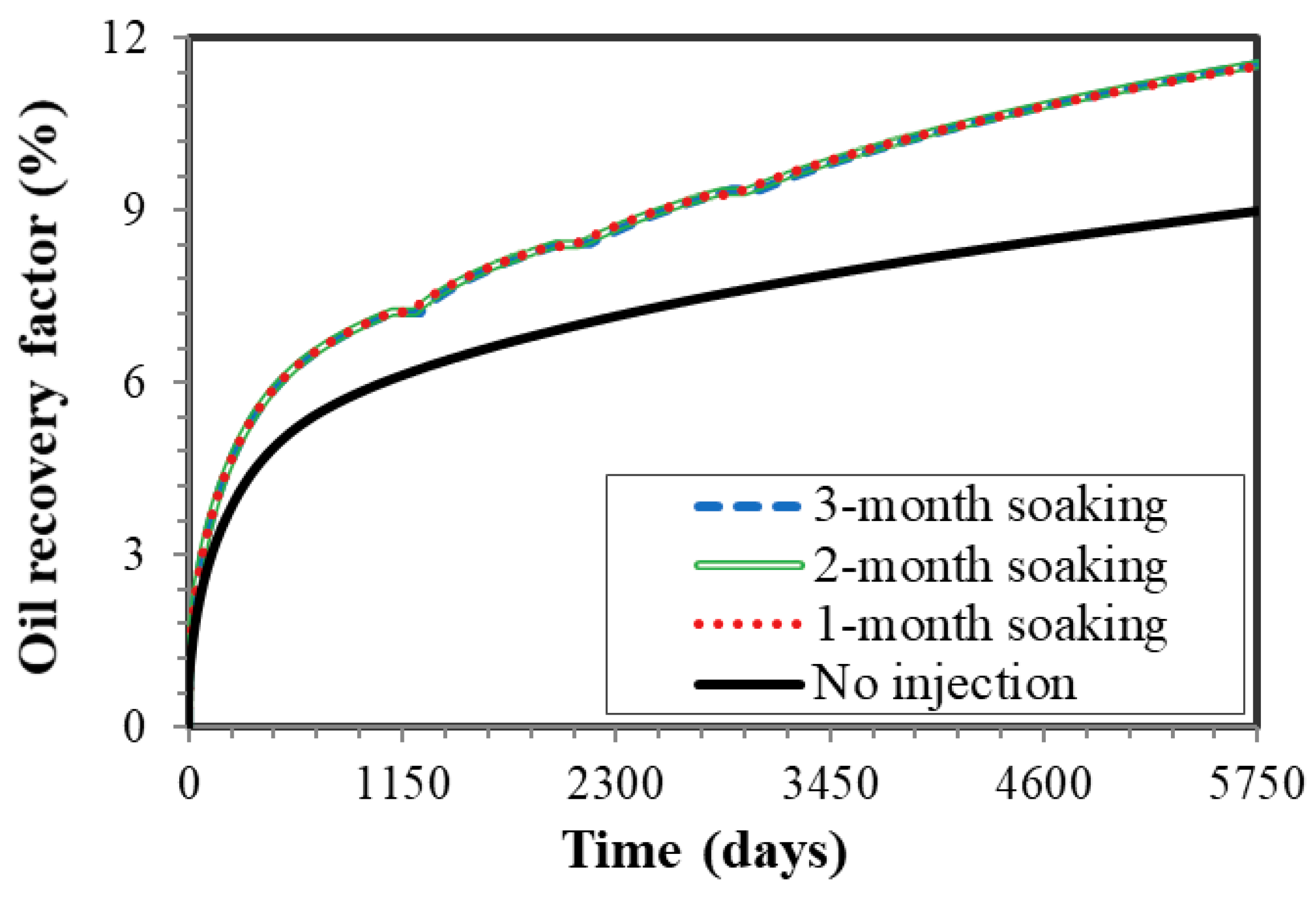
4.6. Effect of Soaking Time
The soaking period affects the performance of Huff-n-Puff process as well. In this section, we conducted three cases with soaking time of 1 month, 2 months, and 3 months. As shown in Figure 12, the cases with the soaking time of 1 month, 2 months, and 3 months lead to the increment of 2.27%, 2.33%, and 2.37% after 15 years, respectively. As soaking period becomes longer, the CH4 molecules will have more time to mix with oil phase adequately before its being produced back. Hence, the oil recovery factor improves with longer soaking time.
4.7. Effect of Number of Cycles
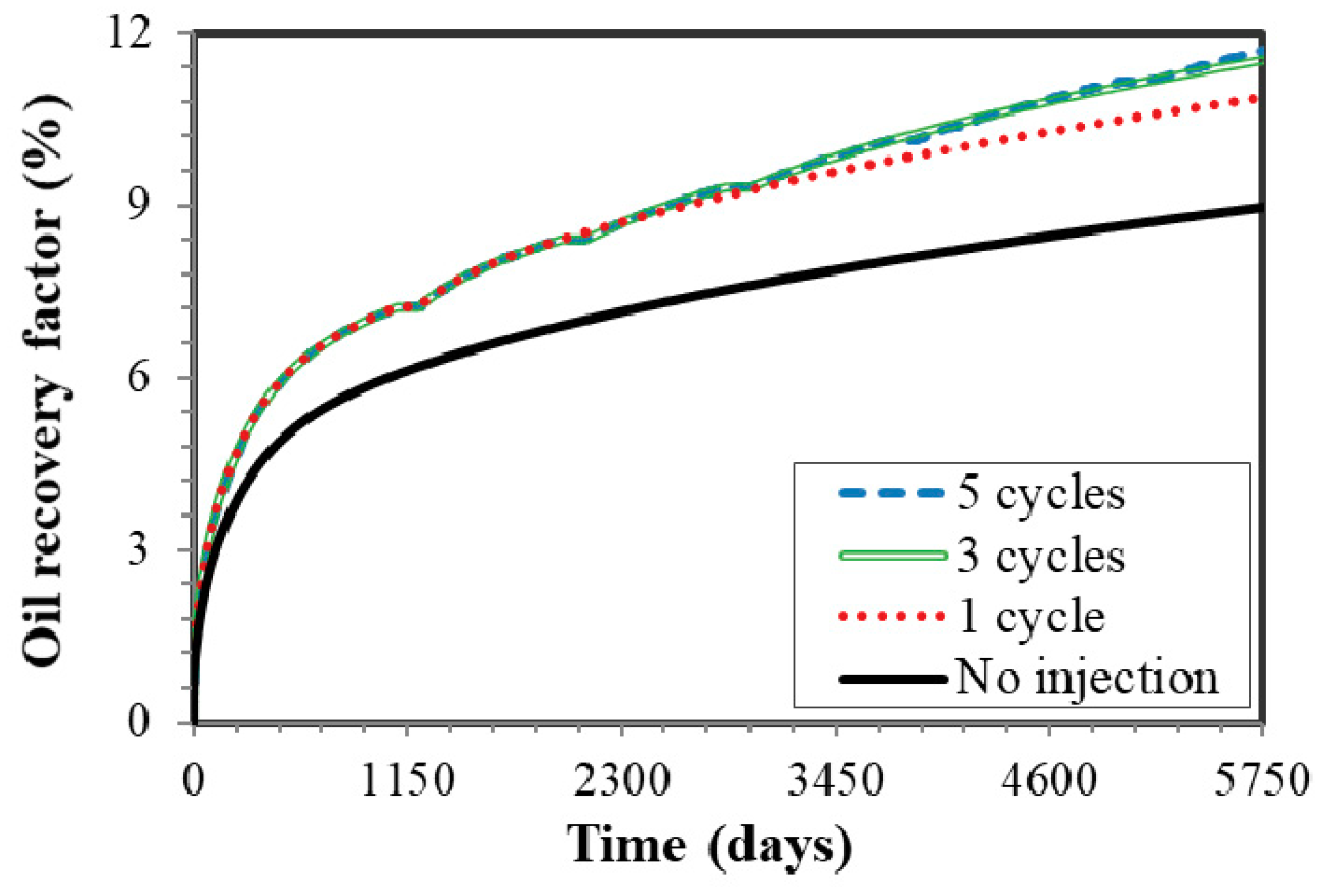
The number of cycles has significant impacts on the CH4 injection effectiveness. We evaluated the well performance of the cases experiencing 1, 3, and 5 cycles, respectively. In Figure 13, compared the oil recovery factor of the scenarios with and without CH4 injection for one-cycle treatment, the incremental oil recovery was boosted by 1.89%. Three-cycle processes yield the increment of 2.52%. For the five-cycle process, the incremental oil recovery is 2.72%. The increase of cycle numbers leads to the large incremental oil recovery; however, when it experiences 3 cycles or more, the impact on the well performance is diminished. Therefore, 3 cycles are suitable to reduce the operation cost and improve the oil production.
4.8. Effect of Matrix Permeability
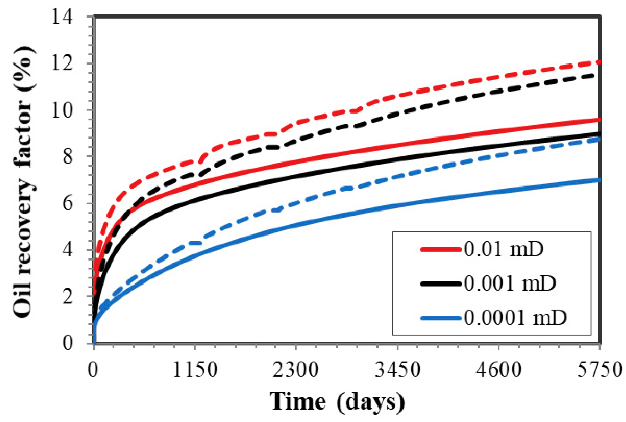
In this section, we analyzed the effect of matrix permeability on the well performance. The matrix permeability was set ranging from 0.0001 mD to 0.01 mD. As shown in Figure 14, the oil recovery factor at the end of 15 years increases by 1.75%, 2.47% and 2.55%, corresponding to 0.0001, 0.001, and 0.01 mD, respectively. The matrix permeability influences the efficiency of CH4 injection and higher permeability leads to larger incremental oil recovery. At the end of primary production, residual oil saturation is larger in the lower permeability formation and the diffusion mechanism is becoming more dominant. If the effect of confinement is included, more noticeable difference on the well performance will be observed in the higher permeability.
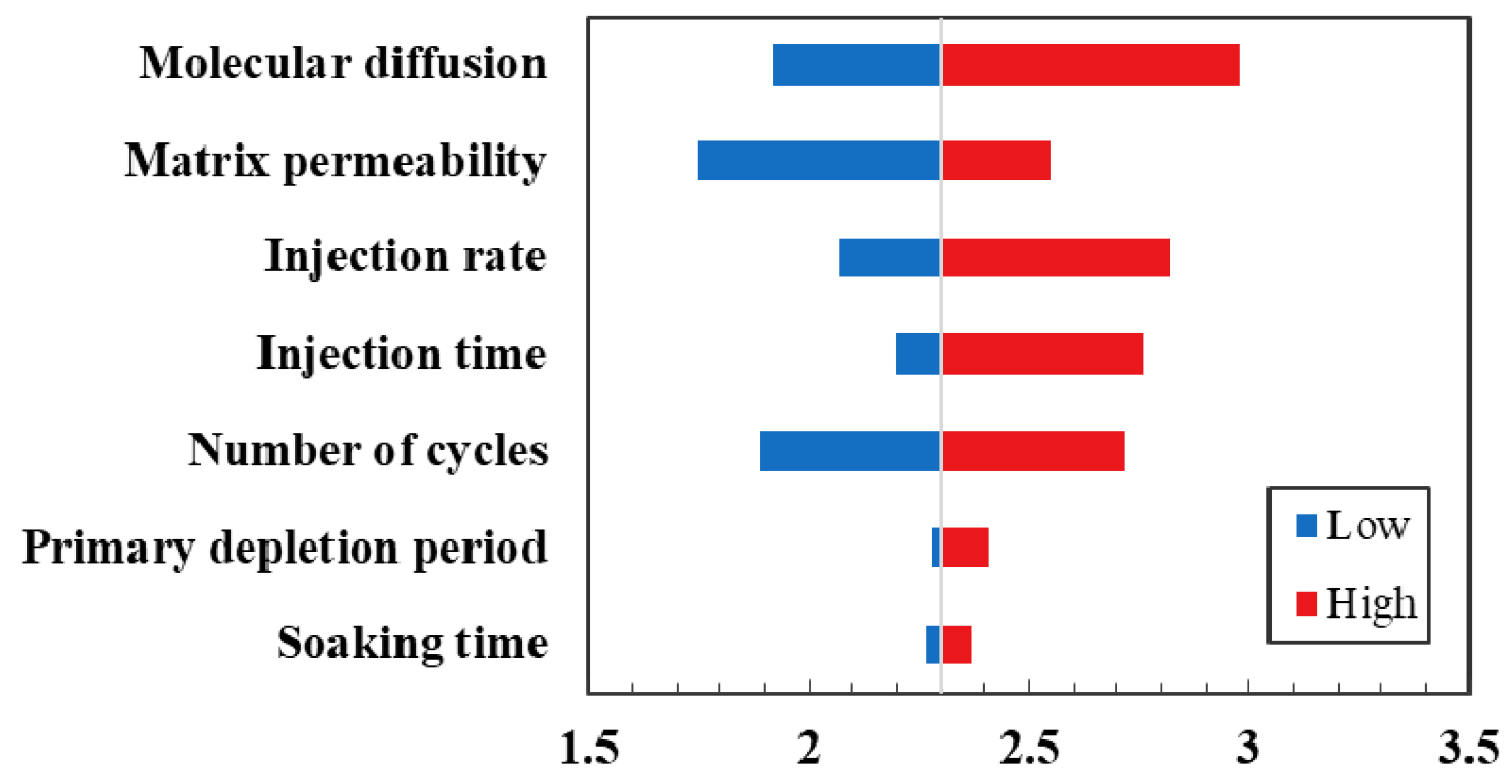
We summarize the sensitivity parameters in Table 5 and represent by tornado plots shown in Figure 15. As shown, the most sensitive parameter for the cyclic CH4 injection is the molecular diffusion, followed by matrix permeability, injection rate, injection time, and number of cycles. Primary depletion period and soaking time play the least important roles during the production time.
5. Conclusions
In this study, a numerical model is proposed to investigate the cyclic CH4 injection in the Eagle Ford shale incorporating physical mechanisms such as molecular diffusion and confinement in nanopores. The following conclusions can be drawn:
- (1)
- The effect of confinement in the nanopores is a significant factor in the simulation model to capture the real mechanism during the cyclic CH4 injection;
- (2)
- A series of simulations were performed to evaluate the impacts of key parameters on the process of enhanced oil recovery, concluding that molecular diffusion is the most sensitive, followed by matrix permeability, injection rate, injection time, and number of cycles;
- (3)
- The impacts of primary depletion period and soaking time are less favorable for the cyclic CH4 injection process;
- (4)
- This work provides a better understanding of factors affecting the efficiency of cyclic CH4 injection, which can hopefully guide the operations in the shale reservoir.
Author Contributions
Conceptualization, Y.Z. and Y.D.; methodology and investigation Y.Z.; writing—original draft preparation, Y.Z.; writing—review and editing, J.H. and Y.S.; project administration, Y.D.; funding acquisition, Y.Z., Y.D. and J.H.
Funding
This research was funded by “National Natural Science Foundation of China, grant number 51804282 and 51674010”, “National Science and Technology Major Project of China, grant number 2017ZX05009-005”, “Fundamental Research Funds for the Central Universities, grant number 59/53200759016”, and “PetroChina Innovation Foundation (2017D-5007-0312)”.
Acknowledgments
We would like to appreciate Computer Modeling Group Ltd. for providing the CMG software for this investigation.
Conflicts of Interest
The authors declare no conflict of interest.
References
- Salahshoor, S.; Fahes, M.; Teodoriu, C. A review on the effect of confinement on phase behavior in tight formations. J. Nat. Gas Sci. Eng. 2018, 51, 89–103. [Google Scholar] [CrossRef]
- Mullen, J. Petrophysical characterization of the Eagle Ford shale in South Texas. In Proceedings of the Canadian Unconventional Resources & International Petroleum Conference, Calgary, AB, Canada, 19–21 October 2010. [Google Scholar]
- Shelley, R.F.; Saugier, L.D.; Al-Tailji, W.; Guliyev, N.; Shah, K. Understanding hydraulic fracture stimulated horizontal Eagle Ford completions. In Proceedings of the SPE/EAGE European Unconventional Resources Conference and Exhibition, Vienna, Austria, 20–22 March 2012. [Google Scholar]
- Zhang, L.; Kou, Z.; Wang, H.; Zhao, Y.; Dejam, M.; Guo, J.; Du, J. Performance analysis for a model of a multi-wing hydraulically fractured vertical well in a coalbed methane gas reservoir. J. Pet. Sci. Eng. 2018, 166, 104–120. [Google Scholar] [CrossRef]
- Dejam, M.; Hassanzadeh, H.; Chen, Z. Semi-analytical solution for pressure transient analysis of a hydraulically fractured vertical well in a bounded dual-porosity reservoir. J. Hydrol. 2018, 565, 289–301. [Google Scholar] [CrossRef]
- Xu, Z.H.; Zhao, P.Q.; Wang, Z.L.; Ostadhassan, M.; Pan, Z.H. Characterization and consecutive prediction of pore structures in tight oil reservoirs. Energies 2018, 11, 2705. [Google Scholar] [CrossRef]
- Qian, K.; Yang, S.L.; Dou, H.E.; Wang, Q.; Wang, L.; Huang, Y. Experimental investigation on microscopic residual oil distribution during CO2 Huff-and-Puff process in tight oil reservoirs. Energies 2018, 11, 2843. [Google Scholar] [CrossRef]
- Dejam, M.; Hassanzadeh, H.; Chen, Z. Pre-Darcy flow in porous media. Water Resour. Res. 2017, 53, 8187–8210. [Google Scholar] [CrossRef]
- Dejam, M.; Hassanzadeh, H.; Chen, Z. Pre-Darcy flow in tight and shale formations. In Proceedings of the 70th Annual Meeting of the APS (American Physical Society) Division of Fluid Dynamics, Denver, CO, USA, 19–21 November 2017. [Google Scholar]
- Hawthorne, S.B.; Gorecki, C.D.; Sorensen, J.A.; Steadman, E.N.; Harju, A.J.; Melzer, S. Hydrocarbon mobilization mechanisms from upper, middle, and lower Bakken reservoir rocks exposed to CO2. In Proceedings of the SPE Unconventional Resources Conference, Calgary, AB, Canada, 5–7 November 2013. [Google Scholar]
- Ren, B.; Ren, S.; Zhang, L.; Chen, G.; Zhang, H. Monitoring on CO2 migration in a tight oil reservoir during CCS-EOR in Jilin Oilfield China. Energy 2016, 98, 108–121. [Google Scholar] [CrossRef]
- Sheng, J.J. Critical review of field EOR projects in shale and tight reservoirs. J. Pet. Sci. Eng. 2017, 159, 654–665. [Google Scholar] [CrossRef]
- Wang, X.; Luo, P.; Er, V.; Huang, S.S. Assessment of CO2 flooding potential for Bakken Formation, Saskatchewan. In Proceedings of the Canadian Unconventional Resources & International Petroleum Conference, Calgary, AB, Canada, 19–21 October 2010. [Google Scholar]
- Sanchez-Rivera, D.; Mohanty, K.; Balhoff, M. Reservoir simulation and optimization of Huff-n-Puff operations in the Bakken shale. Fuel 2015, 147, 82–94. [Google Scholar] [CrossRef]
- Alfarge, D.; Wei, M.; Bai, B. Feasibility of CO2-EOR in shale-oil reservoirs: Numerical simulation study and pilot tests. In Proceedings of the Carbon Management Technology Conference, Houston, TX, USA, 17–20 July 2017. [Google Scholar]
- Meng, X.; Yu, Y.; Sheng, J.J.; Watson, M.; Mody, F. An experimental study on huff-n-puff gas injection to enhance condensate recovery in shale gas reservoirs. In Proceedings of the Unconventional Resources Technology Conference, San Antonio, TX, USA, 20–22 July 2015. [Google Scholar]
- Shi, R.; Kantzas, A. Enhanced heavy oil recovery on depleted long core system by CH4 and CO2. In Proceedings of the SPE International Thermal Operations and Heavy Oil Symposium, Calgary, AB, Canada, 20–23 October 2008. [Google Scholar]
- Gamadi, T.D.; Elldakli, F.; Sheng, J.J. Compositional simulation evaluation of EOR potential in shale oil reservoirs by cyclic natural gas injection. In Proceedings of the Unconventional Resources Technology Conference, Denver, CO, USA, 25–27 August 2014. [Google Scholar]
- Shen, Z.; Sheng, J.J. Experimental study of asphaltene aggregation during CO2 and CH4 injection in shale oil reservoirs. In Proceedings of the SPE Improved Oil Recovery Conference, Tulsa, OK, USA, 11–13 April 2016. [Google Scholar]
- Sigmund, P.M.; Dranchuk, P.M.; Morrow, N.R.; Purvis, R.A. Retrograde condensation in porous media. SPE J. 1973, 13, 93–104. [Google Scholar] [CrossRef]
- Brusilovsky, A.I. Mathematical simulation of phase behavior of natural multicomponent systems at high pressures with an equation of state. SPE Res. Eng. 1992, 7, 117–122. [Google Scholar] [CrossRef]
- Du, L.; Chu, L. Understanding anomalous phase behavior in unconventional oil reservoirs. In Proceedings of the SPE Canadian Unconventional Resources Conference, Calgary, AB, Canada, 30 October–1 November 2012. [Google Scholar]
- Nojabaei, B.; Johns, R.T.; Chu, L. Effect of capillary pressure on phase behavior in tight rocks and shales. SPE Res. Eval. Eng. 2013, 16, 281–289. [Google Scholar] [CrossRef]
- Sanaei, A.; Jamili, A.; Callard, J.; Mathur, A. Production modeling in the Eagle Ford gas condensate window: Integrating new relationships between core permeability, pore size, and confined PVT properties. In Proceedings of the SPE Western North American and Rocky Mountain Joint Meeting, Denver, CO, USA, 16–18 April 2014. [Google Scholar]
- Zhang, Y.; Lashgari, H.R.; Di, Y.; Sepehrnoori, K. Capillary pressure effect on hydrocarbon phase behavior in unconventional reservoirs. In Proceedings of the SPE Low Perm Symposium, Denver, CO, USA, 5–6 May 2016. [Google Scholar]
- Wang, L.; Parsa, E.; Gao, Y.; Ok, J.T.; Neeves, K.; Yin, X.; Ozkan, E. Experimental study and modeling of the effect of nanoconfinement on hydrocarbon phase behavior in unconventional reservoirs. In Proceedings of the SPE Western North American and Rocky Mountain Joint Meeting, Denver, CO, USA, 16–18 April 2014. [Google Scholar]
- Yang, G.; Fan, Z.; Li, X. Determination of confined fluid phase behavior using modified Peng-Robinson equation of state. In Proceedings of the Unconventional Resources Technology Conference, Houston, TX, USA, 23–25 July 2018. [Google Scholar]
- Luo, S.; Nasrabadi, H.; Lutkenhaus, J.L. Effect of confinement on the bubble points of hydrocarbons in nanoporous media. AIChE J. 2016, 62, 1772–1780. [Google Scholar] [CrossRef]
- Alfi, M.; Nasrabadi, H.; Banerjee, D. Effect of confinement on bubble point temperature shift of hydrocarbon mixtures: Experimental investigation using nanofluidic devices. In Proceedings of the SPE Annual Technical Conference and Exhibition, San Antonio, TX, USA, 9–11 October 2017. [Google Scholar]
- Yu, W.; Lashgari, H.R.; Wu, K.; Sepehrnoori, K. CO2 injection for enhanced oil recovery in Bakken tight oil reservoirs. Fuel 2015, 159, 354–363. [Google Scholar] [CrossRef]
- Du, X.D.; Gu, M.; Duan, S.; Xian, X.F. Investigation of CO2–CH4 displacement and transport in shale for enhanced shale gas recovery and CO2 sequestration. J. Energy Resour. Technol. 2017, 139, 012909. [Google Scholar] [CrossRef]
- Zhang, Y.; Yu, W.; Li, Z.; Sepehrnoori, K. Simulation study of factors affecting CO2 Huff-n-Puff process in tight oil reservoirs. J. Pet. Sci. Eng. 2018, 163, 264–269. [Google Scholar] [CrossRef]
- Wu, K.; Li, X.; Guo, C.; Wang, C.; Chen, Z. A unified model for gas transfer in nanopores of shale-gas reservoirs: Coupling pore diffusion and surface diffusion. SPE J. 2016, 21, 1583–1611. [Google Scholar] [CrossRef]
- Chen, C.; Gu, M. Investigation of cyclic CO2 huff-and-puff recovery in shale oil reservoirs using reservoir simulation and sensitivity analysis. Fuel 2017, 188, 102–111. [Google Scholar] [CrossRef]
- Simpson, M.D.; Patterson, R.; Wu, K. Study of stress shadow effects in Eagle Ford Shale: Insight from field data analysis. In Proceedings of the 50th U.S. Rock Mechanics/Geomechanics Symposium, American Rock Mechanics Association, Houston, TX, USA, 26–29 June 2016. [Google Scholar]
- Singh, S.K.; Sinha, A.; Deo, G.; Singh, J.K. Vapor-liquid phase coexistence, critical properties, and surface tension of confined alkanes. J. Phys. Chem. C 2009, 113, 7170–7180. [Google Scholar] [CrossRef]
- Jin, L.C.; Ma, Y.X.; Jamili, A. Investigating the effect of pore proximity on phase behavior and fluid properties in shale formations. In Proceedings of the SPE Annual Technical Conference and Exhibition, New Orleans, LA, USA, 30 September–2 October 2013. [Google Scholar]
- Campos, M.D.; Akkutlu, I.Y.; Sigal, R.F. A molecular dynamics study on natural gas solubility enhancement in water confined to small pores. In Proceedings of the SPE Annual Technical Conference and Exhibition, New Orleans, LA, USA, 4–7 October 2009. [Google Scholar]
- Devegowda, D.; Sapmanee, K.; Civan, F.; Sigal, R.F. Phase behavior of gas condensates in shales due to pore proximity effects: Implications for transport, reserves and well productivity. In Proceedings of the SPE Annual Technical Conference and Exhibition, San Antonio, TX, USA, 8–10 October 2012. [Google Scholar]
- Zarragoicoechea, G.J.; Kuz, V.A. Critical shift of a confined fluid in a nanopore. Fluid Phase Equilib. 2004, 220, 7–9. [Google Scholar] [CrossRef]
- Adamson, A.W. Capillarity. In Physical Chemistry of Surfaces, 5th ed.; John Wiley & Sons: New York City, NY, USA, 1990. [Google Scholar]
- Pedersen, K.S.; Christensen, P.L. Flash and phase envelope calculations. In Phase Behavior of Petroleum Reservoir Fluids, 1st ed.; CRC Press Taylor & Francis Group: Boca Raton, FL, USA, 2006. [Google Scholar]
- Peng, D.Y.; Robinson, D.B. A new two-constant equation of state. Ind. Eng. Chem. Fundam. 1976, 15, 59–64. [Google Scholar] [CrossRef]
- CMG. GEM-GEM User’s Guide; Computer Modeling Group Ltd.: Calgary, AB, Canada, 2012. [Google Scholar]
- Condon, S.M.; Dyman, T.S. Geologic Assessment of Undiscovered Conventional Oil and Gas Resources in the Upper Cretaceous Navarro and Taylor Groups, Western Gul Province; Texas: USGS Digital Data Series; USGU: Reston, VG, USA, 2006. [Google Scholar]
- Mohebbinia, S.; Wong, T. Molecular diffusion calculations in simulation of gasfloods in fractured reservoirs. In Proceedings of the SPE Reservoir Simulation Conference, Montgomery, AL, USA, 20–22 February 2017. [Google Scholar]
- Orangi, A.; Nagarajan, N.R.; Honarpour, M.M.; Rosenzweig, J.J. Unconventional shale oil and gas-condensate reservoir production, impact of rock, fluid, and hydraulic fractures. In Proceedings of the SPE Hydraulic Fracturing Technology Conference and Exhibition, The Woodlands, TX, USA, 24–26 January 2011. [Google Scholar]
Figure 1.
The sketch of CH4 injection process in the fractured horizontal well (CH4 molecules diffuse into different nanopores).
Figure 1.
The sketch of CH4 injection process in the fractured horizontal well (CH4 molecules diffuse into different nanopores).

Figure 2.
The workflow of evaluation of CH4 injection effectiveness.
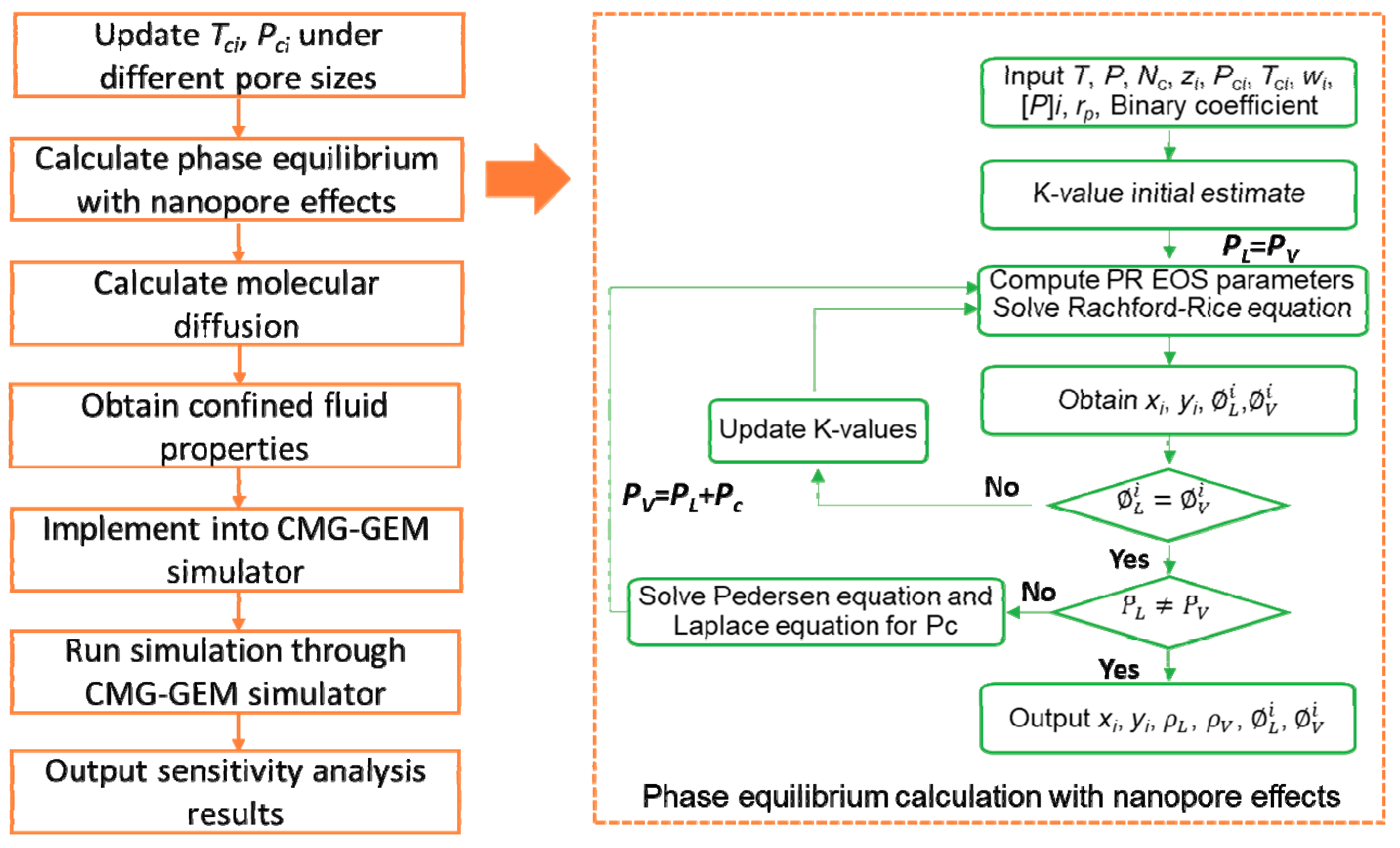
Figure 3.
The reservoir simulation model in the cyclic CH4 injection.

Figure 4.
Relative permeability curves: (a) Water-oil relative permeability curve; (b) Liquid-gas relative permeability curve [38].
Figure 4.
Relative permeability curves: (a) Water-oil relative permeability curve; (b) Liquid-gas relative permeability curve [38].

Figure 5.
Production of different cases in total simulation time of 15 years: (a) Primary production; (b) Cyclic CH4 injection (the yellow, red and dark blue bars represent CH4 injection, soaking and EOR production period, respectively).
Figure 5.
Production of different cases in total simulation time of 15 years: (a) Primary production; (b) Cyclic CH4 injection (the yellow, red and dark blue bars represent CH4 injection, soaking and EOR production period, respectively).

Figure 6.
Bubble point pressure under different pore sizes.

Figure 7.
Effect of nanopore confinement on well performance in a 15-year period.

Figure 8.
Effect of molecular diffusion on well production in a 15-year period.

Figure 9.
Comparison of oil recovery factor of different primary depletion period.

Figure 10.
Comparison of oil recovery factor with different injection rates.

Figure 11.
Comparison of oil recovery factor of different injection time.

Figure 12.
Comparison of oil recovery factor of different soaking time.

Figure 13.
Comparison of oil recovery factor of different cycle treatments.

Figure 14.
Effect of matrix permeability on oil recovery factor after 15 years (the solid and dash line represent the primary production and CH4 injection, respectively).
Figure 14.
Effect of matrix permeability on oil recovery factor after 15 years (the solid and dash line represent the primary production and CH4 injection, respectively).

Figure 15.
Tornado plot for the sensitivity analysis.

Table 1.
Rock and fluid properties used in the reservoir model.
| Properties | Value | Unit |
|---|---|---|
| Initial reservoir pressure | 8125 | psi |
| Reservoir temperature | 270 | °F |
| Reservoir thickness | 100 | ft |
| Water saturation | 17% | - |
| Porosity | 12% | - |
| Average matrix permeability | 0.001 | mD |
| Fracture half-length | 210 | ft |
| Fracture spacing | 80 | ft |
Table 2.
Properties of Eagle Ford oil modified from Orangi et al. [47].
Table 2.
Properties of Eagle Ford oil modified from Orangi et al. [47].
| Components | Mole Fraction (%) | Critical Temperature (K) | Critical Pressure (atm) | Acentric Factor | Molecular Weight (g/mol) |
|---|---|---|---|---|---|
| CO2 | 1.18 | 304.20 | 72.8 | 0.225 | 44.01 |
| N2 | 0.16 | 126.20 | 33.5 | 0.040 | 28.01 |
| CH4 | 11.54 | 190.60 | 45.4 | 0.008 | 16.04 |
| C2-nC5 | 26.44 | 274.74 | 36.5 | 0.172 | 52.02 |
| C6-C10 | 38.09 | 438.68 | 25.1 | 0.284 | 103.01 |
| C11+ | 22.59 | 740.29 | 17.5 | 0.672 | 267.15 |
Table 3.
Binary interaction coefficients for each component.
| Component | CO2 | N2 | CH4 | C2-nC5 | C6-C10 | C11+ |
|---|---|---|---|---|---|---|
| CO2 | 0 | −0.020 | 0.1030 | 0.1299 | 0.1500 | 0.1500 |
| N2 | −0.020 | 0 | 0.0310 | 0.0820 | 0.1200 | 0.1200 |
| CH4 | 0.1030 | 0.0310 | 0 | 0.0174 | 0.0462 | 0.1110 |
| C2-nC5 | 0.1299 | 0.0820 | 0.0174 | 0 | 0.0073 | 0.0444 |
| C6-C10 | 0.1500 | 0.1200 | 0.0462 | 0.0073 | 0 | 0.0162 |
| C11+ | 0.1500 | 0.1200 | 0.1110 | 0.0444 | 0.0162 | 0 |
Table 4.
Critical temperatures and pressures under different pore sizes.
| Components | Critical Temperatures (K) | Critical Pressures (Bar) | ||||||
|---|---|---|---|---|---|---|---|---|
| Bulk | 15 nm | 10 nm | 5 nm | Bulk | 15 nm | 10 nm | 5 nm | |
| CO2 | 304.2 | 296.7 | 293.1 | 282.2 | 73.8 | 72.0 | 71.1 | 68.4 |
| N2 | 126.2 | 123.2 | 121.7 | 117.4 | 33.9 | 33.1 | 32.7 | 31.6 |
| CH4 | 190.6 | 185.9 | 183.6 | 176.8 | 46.0 | 44.9 | 44.3 | 42.7 |
| C2-nC5 | 274.7 | 266.6 | 262.5 | 250.6 | 37.0 | 35.9 | 35.3 | 33.7 |
| C6-C10 | 438.7 | 421.4 | 413.0 | 388.1 | 25.4 | 24.4 | 24.0 | 22.5 |
| C11+ | 740.3 | 701.4 | 682.4 | 627.0 | 17.7 | 16.8 | 16.3 | 15.0 |
Table 5.
Uncertain parameters and ranges for sensitivity analysis.
| Parameters | Minimum | Medium | Maximum |
|---|---|---|---|
| Molecular diffusion/cm2/s | 0.0001 | 0.001 | 0.01 |
| Primary depletion period/year | 2 | 3 | 5 |
| Injection time/day | 30 | 60 | 90 |
| Injection rate, Mscf/day | 2000 | 5000 | 8000 |
| Soaking time/day | 30 | 60 | 90 |
| Number of cycles | 1 | 3 | 5 |
| Matrix permeability, mD | 0.001 | 0.01 | 0.1 |
© 2018 by the authors. Licensee MDPI, Basel, Switzerland. This article is an open access article distributed under the terms and conditions of the Creative Commons Attribution (CC BY) license (http://creativecommons.org/licenses/by/4.0/).
Share and Cite
MDPI and ACS Style
Zhang, Y.; Di, Y.; Shi, Y.; Hu, J. Cyclic CH4 Injection for Enhanced Oil Recovery in the Eagle Ford Shale Reservoirs. Energies 2018, 11, 3094. https://doi.org/10.3390/en11113094
AMA Style
Zhang Y, Di Y, Shi Y, Hu J. Cyclic CH4 Injection for Enhanced Oil Recovery in the Eagle Ford Shale Reservoirs. Energies. 2018; 11(11):3094. https://doi.org/10.3390/en11113094
Chicago/Turabian StyleZhang, Yuan, Yuan Di, Yang Shi, and Jinghong Hu. 2018. "Cyclic CH4 Injection for Enhanced Oil Recovery in the Eagle Ford Shale Reservoirs" Energies 11, no. 11: 3094. https://doi.org/10.3390/en11113094
Note that from the first issue of 2016, this journal uses article numbers instead of page numbers. See further details here.