Symmetrical Loss of Excitation Fault Diagnosis in an Asynchronized High-Voltage Generator


1
School of Electrical and Electronic Engineering, Harbin University of Science and Technology, Harbin 150080, China
2
State Grid Heilongjiang Electric Power Company Limited Electric Power Research Institute, Harbin 150030, China
*
Author to whom correspondence should be addressed.
Energies 2018, 11(11), 3054; https://doi.org/10.3390/en11113054
Submission received: 21 October 2018
/
Revised: 4 November 2018
/
Accepted: 4 November 2018
/
Published: 6 November 2018
(This article belongs to the Special Issue Fault Diagnosis in Electric Motors)
Abstract
:As a new type of generator, an asynchronized high-voltage generator has the characteristics of an asynchronous generator and high voltage generator. The effect of the loss of an excitation fault for an asynchronized high-voltage generator and its fault diagnosis technique are still in the research stage. Firstly, a finite element model of the asynchronized high-voltage generator considering the field-circuit-movement coupling is established. Secondly, the three phase short-circuit loss of excitation fault, three phase open-circuit loss of excitation fault, and three phase short-circuit fault on the stator side are analyzed by the simulation method that is applied abroad at present. The fault phenomenon under the stator three phase short-circuit fault is similar to that under the three phase short-circuit loss of excitation. Then, a symmetrical loss of the excitation fault diagnosis system based on wavelet packet analysis and the Back Propagation neural network (BP neural network) is established. At last, we confirm that this system can eliminate the interference of the stator three phase short-circuit fault, accurately diagnose the symmetrical loss of the excitation fault, and judge the type of symmetrical loss of the excitation fault. It saves time to find the fault cause and improves the stability of system operation.
1. Introduction
One of the most common faults in the excitation circuit of a generator is that they sometimes lose a part or all of the excitation suddenly. The most common causes of loss of excitation include: Failure of excitation power, failure of excitation winding, accidental tripping of the field breaker, failure of auto-excitation equipment, artificial omission, and so on. These lead to partial overheating of the generator, overcurrent in the system components, breakdown of the power system, and it might endanger the stable operation of the large generator. The asynchronized high-voltage generator is a new type of generator that has the advantages of both asynchronized synchronous generators and high-voltage generators (also called Powerformer). The Powerformer is a new type of generator whose stator winding adopts a high-voltage cross-linked polyethylene (XLPE) cable with a circular cross section. The extra-high-voltage generator can output the high voltage and connect directly to the power grid to completely replace the generators, the generator surge arresters, generator-side switches, busbar, and step-up transformers in any conventional power plant [1]. The asynchronized synchronous generators have the following advantages over the traditional generators: The active power, reactive power, and speed can be adjusted independently; power generation with variable-speed and constant-frequency; deep lead phase operation is also possible [2]. Numerous studies have been conducted to study the static stability of asynchronized synchronous generators [3,4] and the operation action for asynchronized turbogenerators with excitation disappearance [5].
In the past decade, the research on the loss of excitation faults for the Powerformer have shown that the Powerformer can enter a stable asynchronous operation state within a short period of time [6], and its stator current will increase to 1.2~1.5 times after a loss of excitation [7]. This research group used the modulus maximum detection method of wavelet transform to analyze the electrical quantity signal during the loss of excitation fault and determined the loss of excitation protection scheme for the Powerformer. The protection scheme can effectively prevent the misoperation of the protection device when the system is under a short-circuit fault and oscillation [8]. If we focus on the changes of electrical quantities after a loss of excitation for asynchronized high-voltage generators and adopt an effective loss of excitation fault diagnosis technique, the loss of excitation fault can be accurately determined and remedied in time to ensure the safe and stable operation of the power system. Therefore, it is extremely necessary to investigate the fault diagnosis for asynchronized high-voltage generators.
Numerous studies have been done to diagnose the loss of the excitation fault of the generator by measuring the rotor signals [9] and the changes in resistance and reactance [10,11]. The main shortcoming of these approaches is that they are not sensitive to the type of the loss of excitation. Some scholars have distinguished the loss of excitation and system disturbance by detecting terminal voltage and reactive power, which is easy to implement, but it requires extensive time-domain simulation studies for relay settings. There are also many studies of the diagnosis fault by the method of wavelet packet analysis and neural network, which can effectively diagnose faults [12,13,14]. Fault diagnosis has important effects on the operation of complex dynamical systems specific to modern industry applications, such as industrial electronics [15,16,17,18]. Some studies take electrical quantities as inputs of the neural network to diagnose a loss of excitation fault, and other studies apply the wavelet transform, which can extract information from the transient signals simultaneously in both the time and frequency domain [19]. If we combine wavelet analysis with the neural network, we can get more accurate fault diagnosis results.
The probability of single-phase loss of excitation is greater than that of three phase loss of excitation, but the influence of three phase loss of excitation on the power grid is greater than that of single-phase loss of excitation, so the three phases loss of excitation fault needs a more accurate diagnosis comparing with the single-phase loss of excitation. This paper analyses the change of electrical quantity after a symmetrical loss of excitation fault, and establishes a symmetrical loss of the excitation fault diagnosis system for the asynchronized high-voltage generator. We introduce a logical unit to the fault diagnosis system based on the loose combination method of wavelet packet analysis and BP neural network, which can effectively diagnose the type of symmetrical loss of the excitation fault and improve the accuracy of fault diagnosis results.
2. The Loss of Excitation Simulation Model for the Asynchronized High-Voltage Generator
The field-circuit-movement coupling method needs to solve the electromagnetic field equations, winding circuit equations, and mechanical equations of the generator simultaneously [20]. This method not only analyses the loss of excitation faults from a magnetic field and electrical quantity, but also simulates the actual running state of the generators. Since many tests of large generators cannot be done with a prototype, some scholars use finite element analysis methods or circuit analysis methods to simulate the generators. The large generator mentioned in this paper cannot do a loss of excitation test on the grid-connected mode, so the field-circuit-movement coupling method is more suitable for the analysis of the asynchronized high-voltage generator. We establish the finite element model and external circuit of the asynchronized high-voltage generator in the following section.
2.1. Finite Element Model
2.2. External Circuit Model
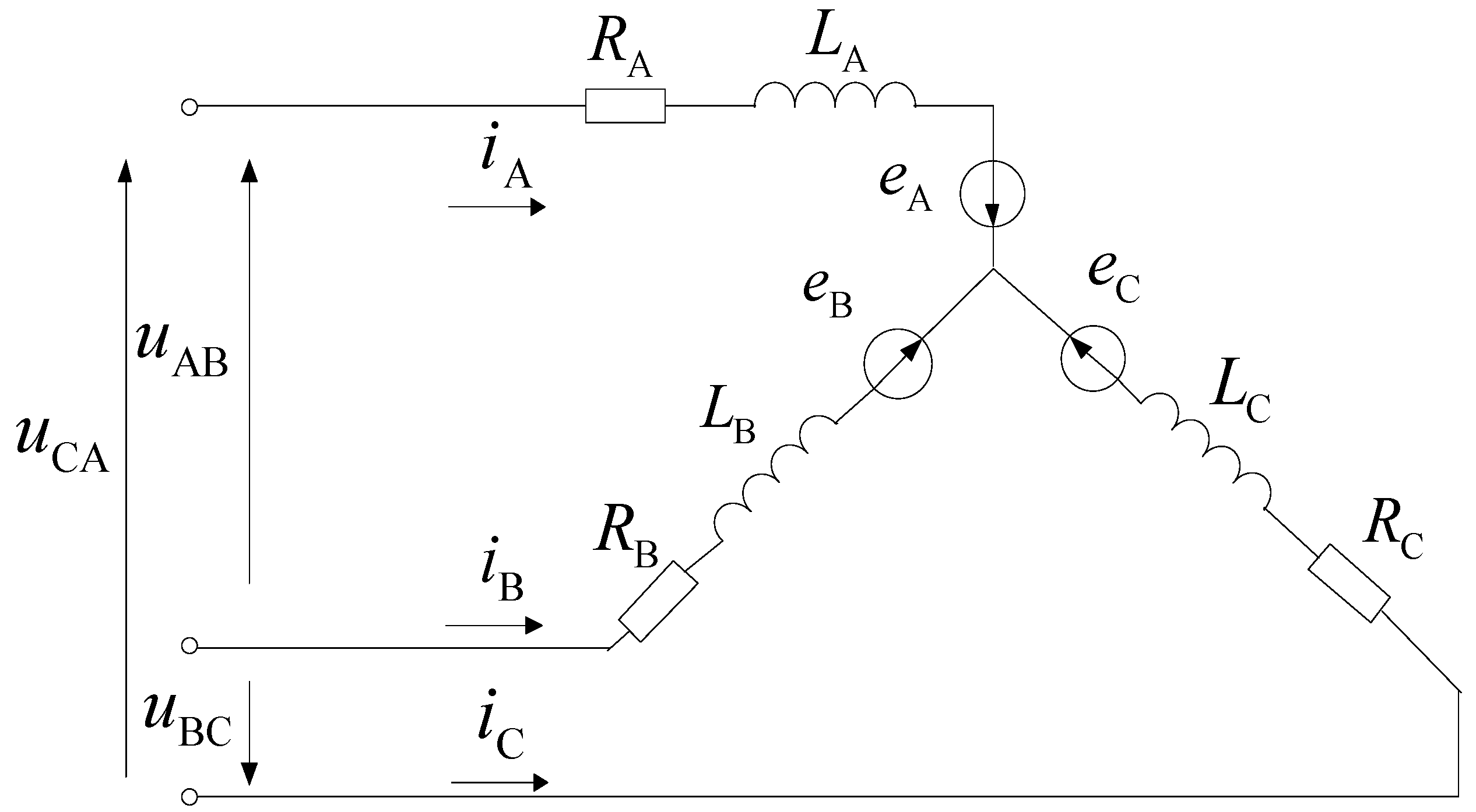
The stator windings of the asynchronized high-voltage generator are star-connected and their equivalent grid-connected circuit is shown in Figure 2.
In Figure 2, eA, eB, and eC are the stator induced electromotive forces of each phase; uA, uB, and uC are the stator voltages of each phase; RA, RB, and RC are the stator resistances of each phase; and LA, LB, and LC are the stator winding inductances of each phase. The circuit equations of the stator winding can be obtained from Figure 2:
In Equation (1), the phase winding induced electromotive force can be expressed by the vector magnetic potential as shown in Equation (2):
where NS is the number of turns per slot winding (or the number of turns of excitation winding); S is the total area of the conductive area of the outflow or inflow end of a phase current (or excitation current), such as A or X; N is the sum of the units that flow into and out the conductive area of a phase winding; Leff is the axial effective length of the motor. When the unit is located in the conductive area of A, B, and C, such as the current inflow terminal of the winding, p = 1; otherwise, p = −1.
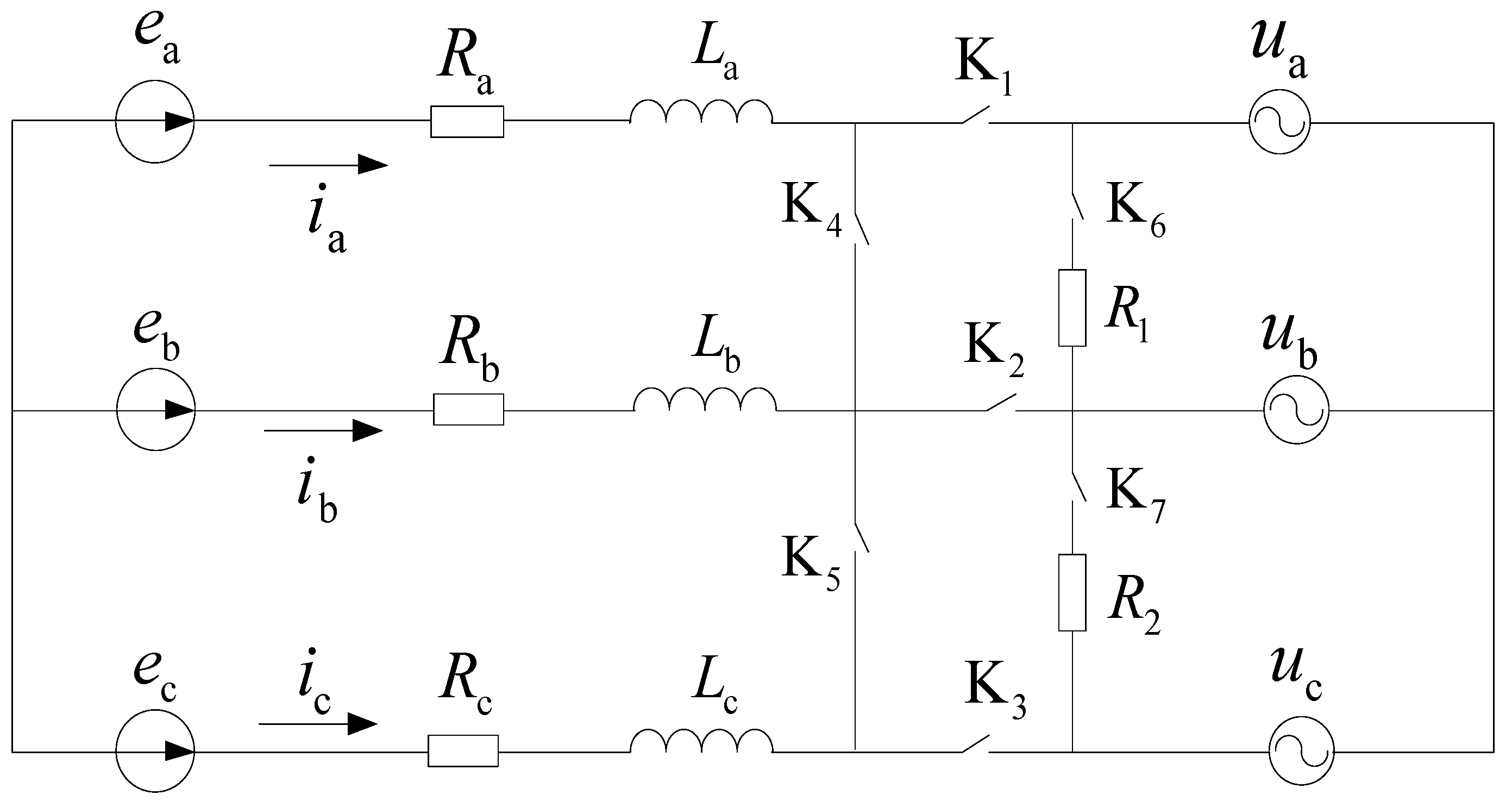
The equivalent circuit of rotor winding for the asynchronized high-voltage generator from a normal operation state to the loss of excitation fault is shown in Figure 3.
In Figure 3, ea, eb, and ec are the rotor induced electromotive forces of each phase. ua, ub, and uc are the rotor voltages of each phase. Ra, Rb, and Rc are the rotor resistances of each phase. La, Lb, and Lc are the rotor winding inductances of each phase. R1 and R2 are short-circuit resistances. When the switches, K1, K2, and K3, are closed, and K4, K5, K6, and K7 are open, the generator runs normally; when the switches, K1, K2, and K3, are open and K4, K5, K6, and K7 are closed, the generator is under the three phase short-circuit loss of excitation; when all the switches are open, the generator is under the three phases open-circuit loss of excitation.
According to Figure 3, the circuit equations of the rotor winding are:
The circuit matrix equation is listed according to the equivalent circuit as shown in Equation (4):
where k1, k2, and k3 are used to control the degree of loss of excitation; when k1 = k2 = k3 = −1, the generator is under three phase short-circuit loss of excitation and when k1 = k2 = k3 = , it is under the three phase open-circuit loss of excitation. Here, k is controlled by the switch in Figure 3. Uf and If are column vectors composed of three-phase voltage and the current of the rotor, respectively; N, Rr, and Lr are the corresponding coefficient matrix of the rotor.
By combining Equations (2) and (4), the coupling equations of the field circuit of the asynchronized high-voltage generator can be obtained as follows:
2.3. The Field-Circuit-Movement Coupling Simulation Model
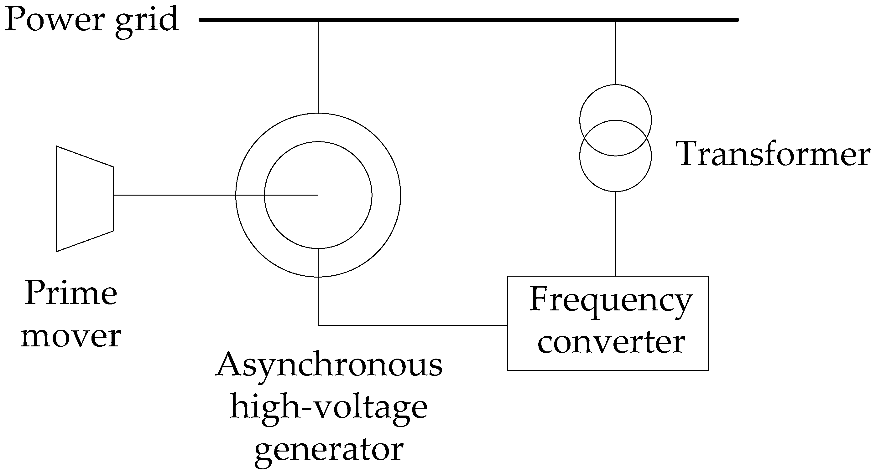
The system of the asynchronized high-voltage generator is shown in Figure 4.
In Figure 4, the stator of the asynchronized high-voltage generator can be directly connected to the power grid, which matches its voltage. The phase, frequency, and amplitude of the rotor can be adjusted by the frequency converter, which is connected with the rotor. In addition, the generator requires a prime mover to drive the rotor to rotate.
Based on Section 2.1 and Section 2.2, and Figure 4, a field-circuit-movement coupling simulation model for the loss of excitation faults is established, which is shown in Figure 5.
In Figure 5, the finite element model is added in an external circuit to form a field-circuit-movement coupling simulation model. The prime mover is simulated by adjusting the parameters of the component. The stator side of the generator is connected in parallel with the infinite power system, the rotor side provides excitation through a voltage source, and the switch is controlled by the step function.
2.4. Model Verification
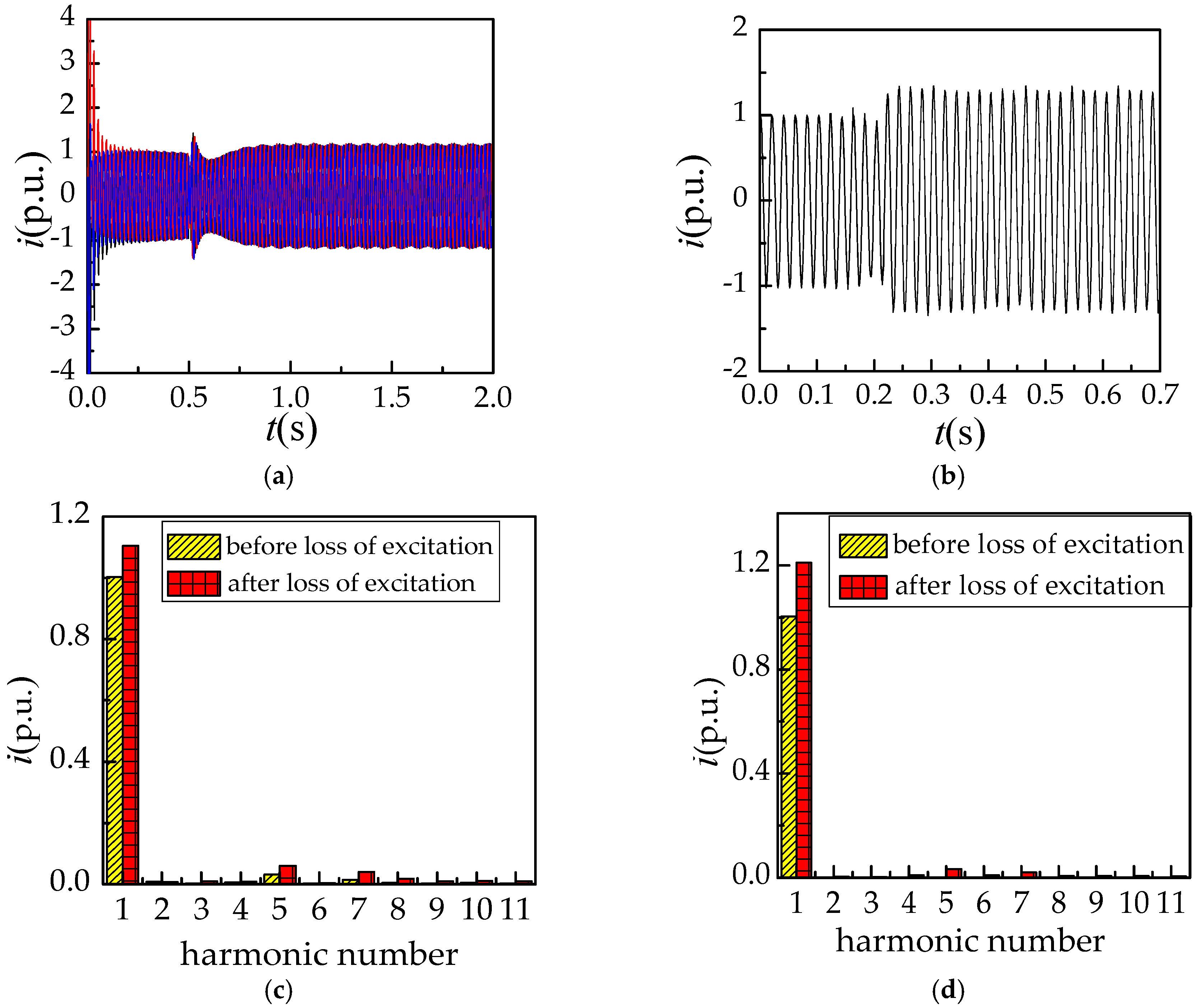
The above asynchronized high-voltage generator prototype is used for testing. The above simulation model is correctness by test results. The basic parameters of the test prototype are shown in Table 1. In the test process, the asynchronized high-voltage generator is rated operation, and then the three phase short circuit is conducted on its excitation winding. The test platform is shown in Figure 6. Test results are shown in Figure 7 as (b) and (d), and the fault occurs at 0.2 s. Simulation analysis process was conducted according to the same conditions, and the fault occurs at 0.5 s. The simulation results are shown in Figure 7 as (a) and (c).
When the generator is running in a sub-synchronous state (s = 0.08), the stator current and harmonic analysis under the three phase short-circuit loss of excitation is shown in Figure 7. The currents after a loss of excitation increase first in Figure 7a,b, and then decrease. They increase finally and the maximum impact current reaches about 1.2 times of the rated current. In Figure 7c, it can be seen that 5 and 7 harmonics of stator current increase after loss of excitation, while the other harmonics increase less. Using the dynamic simulation laboratory test platform, the generator is used to conduct the loss of excitation fault test, and the stator current obtained from the test is analyzed harmonically. The stator current after a loss of excitation is increased at first, decreases then increases, and the maximum impact current has increased 1.2 times from the rate current. In Figure 7c, it can be seen that 5 and 7 harmonics of stator current has increased after a loss of excitation, while the other harmonics has increased less. The results of the experimental analysis are shown in Figure 7d. It can be seen that the increase of 5 and 7 harmonics after a loss of excitation is smaller, which is consistent with the simulation results. The correctness of the fault simulation model is verified. Therefore, the simulation model can be used to analyze the running state of the asynchronized high-voltage generator.
3. Analysis of Simulation Results for the Asynchronized High-Voltage Generator
In this paper, we perform the simulations of the three phase short-circuit loss of excitation, three phase open-circuit loss of excitation, and stator three phase short-circuit fault for the asynchronized high-voltage generator in synchronous (s = 0), oversynchronous (s < 0) and subsynchronous (0 < s < 1) operation states. The generator is connected in parallel with the infinite power system and has entered a stable rated operation state before it fails. The fault occurs at 0.5 s. We will take the generator in the subsynchronous operation state as an example for analysis below.
3.1. Analysis of Symmetrical Loss of Excitation Simulation Results
3.1.1. Analysis of Magnetic Field under the Three Phase Short-Circuit Loss of Excitation
The distribution of the magnetic field for the asynchronized high-voltage generator can be obtained by the field-circuit-movement coupling finite element analysis method. Figure 8a,b show the distributions of the magnetic field under one pole of the generator with a rated load in normal operation and the three phase short-circuit loss of excitation, respectively.
It can be seen from Figure 8 that when the generator is in normal operation, the magnetic field is distributed evenly, and the highest magnetic field is about 1.8 T, which meets the design requirement of the generator. When the generator is under the three phases short-circuit loss of excitation, the magnetic field established by the excitation winding is weakened significantly. However, the stator is connected in parallel with the infinite power system and the generator absorbs energy from the system to supplement the weakened magnetic field, which increases the local magnetic field, so the highest magnetic field is about 0.2 T higher than that in normal operation.
3.1.2. Analysis of Electrical Quantities under Three Phase Short-Circuit Loss of Excitation
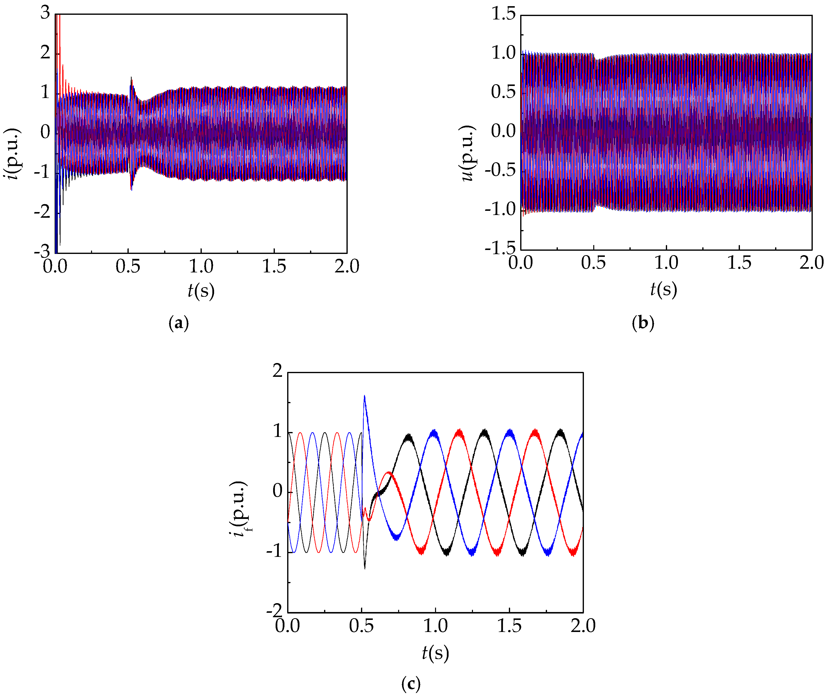
At the moment of the asynchronized high-voltage generator under the three phase loss of excitation in the subsynchronous operation state, the rotor speed is less than the synchronous speed, so the stator windings absorb energy from the infinite power system to increase the current. Then, the generator generates a driving torque that increases the speed further. The asynchronous torque will not change from the driving property to the braking property until the slip rate changes from positive to negative, so the stator current initially increases to 1.5 times of the rated current and then decreases and increases again. Finally, the generator will enter a stable asynchronous operation state and the stator current will fluctuate around 1.2 times of the rated current. The waveform of the stator current is shown in Figure 9a. The stator induced voltage after a loss of excitation decreases slightly, but its change is not obvious because the generator is connected in parallel with the infinite power system, making it consistent with the grid voltage. The waveform of the stator induced voltage is shown in Figure 9b.
The rotor current of the asynchronized high-voltage generator before loss of excitation in the subsynchronous state is an alternating current (AC). At the moment of the three phase short-circuit loss of excitation, the rotor current has a sharp increase, and then the induced current appears in the excitation circuit because the stator is still connected in parallel with the infinite power system. The frequency of the rotor current also changes after the fault. The waveform of the rotor current is shown in Figure 9c.
In this paper, the three phase short-circuit loss of excitation fault at different slip rates are simulated. As shown in Figure 10, it is proved that the maximum increase multiple of stator current at the moment of loss of excitation becomes larger with the increase in the absolute value of slip rate, s. However, when the generator enters the stable asynchronous operation state after the loss of excitation, the increase multiple tends to be consistent, which is 1.2 times.
3.1.3. Analysis of Loss of Excitation Electrical Quantities under Three Phase Open-Circuit
In order to determine the type of the loss of excitation fault, this paper simulates the three phase open-circuit loss of excitation fault, extracts the stator and rotor electrical quantities, and provides a powerful basis for fault diagnosis.
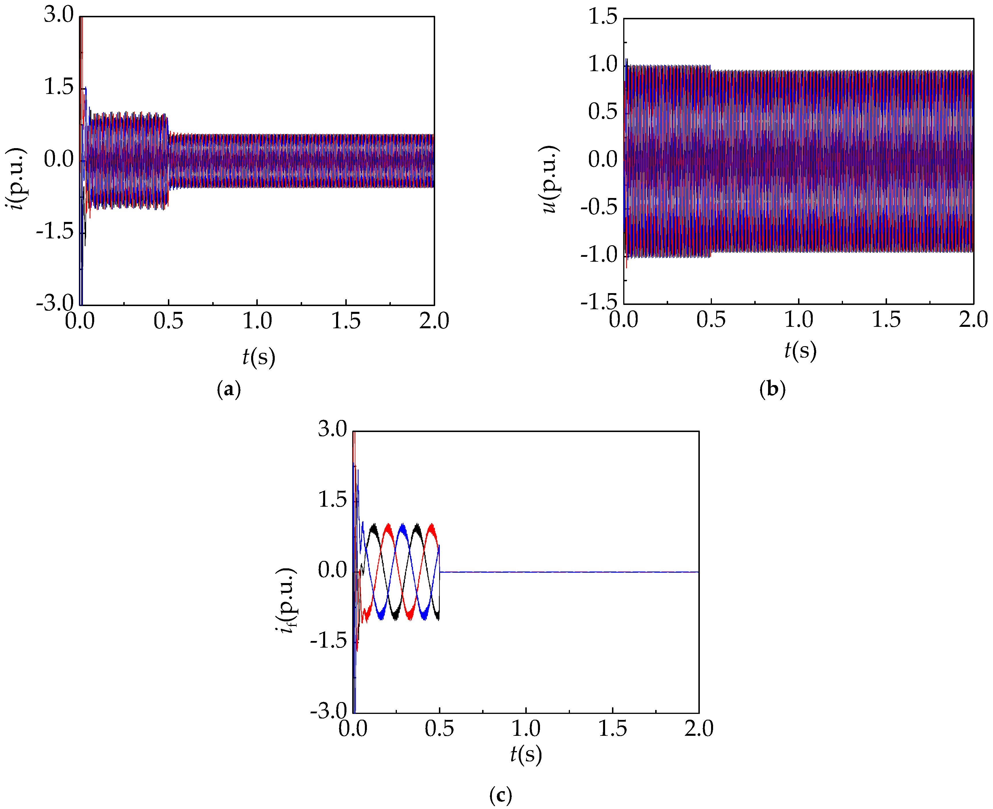
At the time of the three phase open-circuit loss of excitation, the rotor current becomes zero. As the rotor excitation disappears, the stator current and the stator voltage also decrease accordingly. However, the change of the stator voltage is not obvious because the stator is still connected in parallel with the infinite power system. The waveforms of the stator current, the stator induced voltage, and the rotor current are shown in Figure 11.
3.2. Analysis of the Three Phase Short-Circuit Fault on the Stator Side Simulation Results
After the three phase short-circuit loss of excitation fault, the stator current of the asynchronized high-voltage generator is larger than that of the Powerformer [7], and the fault phenomenon is similar to that under the three phase short-circuit fault on the stator side. A three phase short-circuit fault is established on the stator side simulation model for the asynchronized high-voltage generator and system [21,22,23].
The waveform of the stator current is shown in Figure 12a. At the moment of the three phase short-circuit fault on the stator side, the stator current momentarily increases to about 10 times. Additionally, then, the stator appears an induced current because the rotor still has the excitation function. As shown in Figure 12b, the stator voltage momentarily drops to around zero. The rotor current suddenly increases to about 12 times after the loss of excitation fault. Then, the rotor current decreases. At the same time, the frequency and current amplitude return to be consistent with them in the rated operation state. The waveform of the rotor current is shown in Figure 12c.
By the comparison of the simulation waveforms of the stator current under the stator three phase short-circuit fault and the three phases short-circuit loss of excitation, we can find that the stator current of both faults suddenly increases and then decreases. The maximum increase multiple of the stator current increases to about eight to 11 times after the three phases short-circuit fault on the stator side. The maximum increase multiple of the stator current is up to five times after the three phase short-circuit loss of excitation when the slip rate is 0.2, and the study in Section 3.1.2 shows that the maximum increase multiple of the stator current rises with the increase in the absolute value of the slip rate. Therefore, it is necessary to adopt an effective fault diagnosis technique to distinguish the three phases short-circuit loss of excitation fault and three phases short-circuit fault on the stator side, which lays the foundation for the protection of the asynchronized high-voltage generator and system.
4. Symmetrical Loss of Excitation Fault Diagnosis System Based on Wavelet Packet and BP Neural Network
4.1. The Composition of the Fault Diagnosis System
This paper establishes a symmetrical loss of excitation fault diagnosis system based on the wavelet packet and BP neural network. The diagram of the system structure is shown in Figure 13, which includes the transformer module, data processing module, fault diagnosis module, and interface module.
The functions of each module in the symmetrical loss of excitation fault diagnosis system will be described separately below:
- (1)
- The transformer module is applied to acquire the stator current signal, stator voltage signal, and rotor current signal of the asynchronized high-voltage generator. The collected signals include: The signal when the generator is in the normal operation state, the signal when the generator is under the three phase short-circuit loss of excitation fault, the signal when the generator is under the three phase open-circuit loss of excitation fault, and the signal when the generator is under the three phase short-circuit fault on the stator side.
- (2)
- The outputs of the transformer module act as the inputs to the data processing module. The data processing module applies the wavelet packet analysis method to obtain the energy eigenvector of each frequency band for the rotor voltage signal, the stator voltage signal, and the stator current signal.
- (3)
- The outputs of the data processing module act as the inputs to the fault diagnosis module. The fault diagnosis module comprises a neural network, W1; a neural network, W2; a neural network, W3; and a logical operation unit. Firstly, the energy eigenvector of the stator current signal extracted by the wavelet packet analysis is used as an input vector of the neural network, W1. Then, we obtain the fault state, G1, through neural network training. Similarly, we obtain the fault state, G2, and fault state, G3, through the stator voltage and rotor current signal, respectively. Last, the fault states, G1, G2, and G3, are used as the inputs of the logical unit, which outputs the fault state, G.
- (4)
- The interface module is configured to display the fault state obtained by the fault diagnosis module.
4.2. The Wavelet Packet Analysis
The steps of wavelet packet analysis are, as following:
- The fourth-order wavelet of the Daubenchies wavelet series is used to perform three-layer wavelet packet decomposition on the sample signal, which have good localization in both time and frequency domains. The decomposition structure is shown in Figure 14. S is the total reconstructed signal, A represents a low frequency, D represents a high frequency, and the serial number at the end represents the number of wavelet packet decomposition layers.
- Reconstruct the decomposition coefficients of wavelet packets in each layer. The decomposition relationship is S = AAA3 + DAA3 + ADA3 + DDA3 + AAD3 + DAD3 + ADD3 + DDD3.
- Suppose the corresponding energy of Si is Ei′. The total energy of each sub-band signal is:In Equation (3): xi,k is the magnitude of the discrete point for the reconstructed signal, Si; i = 0, 1, 2, …, 7; k = 1, 2, …, n; n is the number of the signal sampling points.
- When the energy is high, Ei′ is usually a large number and the calculation will be complicated, so the energy value needs to be normalized, that is:
The normalized energy value is used as the element of the eigenvector, and the energy eigenvector is constructed as:
4.3. The BP Neural Network
According to the Kolmogorov theorem, the three-layer BP neural network is adopted, which includes an input layer, hidden layer, and output layer. The number of neuron nodes in the input layer n is 8, which is the number of energy eigenvector obtained through wavelet packet analysis; the number of neuron nodes in the output layer m is 3; the number of neuron nodes in the hidden layer, h, satisfies the formula: , where a is an adjustment constant whose range is from 1 to 10. Therefore, h is in the range of 5 to 14. According to the actual condition, the value is 14 in this paper. The hidden layer neurons select the S-type tangent function as the activation function, and the output layer neurons select the S-type logarithmic function as the activation function. Based on experience, the maximum number of training is 1000, the target error is 0.001, and the learning rate is 0.1.
The effective fault symptom vectors are obtained by wavelet packet analysis in the signals of the stator current and voltage and the rotor current, respectively. The fault symptom vector was used as input of the neural network, and we selected the stator current, stator voltage, and rotor current as training samples. The Levenberg-marquardt algorithm was used for neural training. The Levenberg-Marquardt (L-M) algorithm is actually a combination of the gradient descent method and the Newton method, which can improve the learning efficiency. The training process is divided into two stages. In the first stage (forward propagation process), the given input information is processed by the hidden layer through the input layer, and the actual output value of each unit is calculated; in the second stage (back propagation process), if the desired output value is not obtained at the output end, the difference between the actual output and the expected output (that is, the error) is calculated recursively layer by layer. According to the error adjustment weight, the control error is within the allowable range, and three fault states, G1, G2, and G3, are the output. The neural network training is completed. The weights obtained from training are stored in the corresponding database. Then, we selected some test samples, and only the forward transmission of signals was found during the test. The connection weight in the BP neural network is no longer changed until the output fault state, G1, G2, and G3.The neural network has been tested. Finally, the fault state, G1, G2, and G3, are input to the logical operation unit.
4.4. The Logical Unit
The logical unit includes AND gates, L1, L2, L3, L4, L5, and L6, and the OR gate L7. The structure diagram of the logical unit is shown in Figure 15. The signals, G1 and G2, pass through the AND gate, L1. If the signals, G1 and G2, are the same, the AND gate, L1, outputs 1; if the signals, G1 and G2, are different, L1 outputs 0. The output of L1 and the signal, G1, pass through the AND gate, L4, when signal L1 is 0, the output of L4 is also 0; when L1 is 1, the output of L4 is signal, G1. Together with the outputs of gates, L4, L5, and L6, they are used as the inputs of OR gate, L7, if there are two or more fault states are consistent, the fault state, G, outputs the fault state; if the three fault states are different from each other, the fault state, G, output is 0. The fault state output of 0 indicates that the algorithm is not ideal, or the fault is out of range of the fault diagnosis, the system will output all fault states to the technician for analysis.
4.5. Analysis of Fault Diagnosis Results
This paper extracts the stator current signals from the generator in normal operation, three phase short-circuit loss of excitation fault, three phase open-circuit loss of excitation fault, and three phase short-circuit fault on the stator side. We select 15 groups as training samples and eight groups as test samples. The wavelet packet energy values of each sub-band after wavelet packet analysis are shown in Table 2. In Table 2, “normal” means the generator in the normal operation state; “Fault 1” means the generator under the three phase short-circuit loss of excitation; “Fault 2” means the generator under the three phase open-circuit loss of excitation; and “Fault 3” means the generator under the stator three phase short-circuit fault.
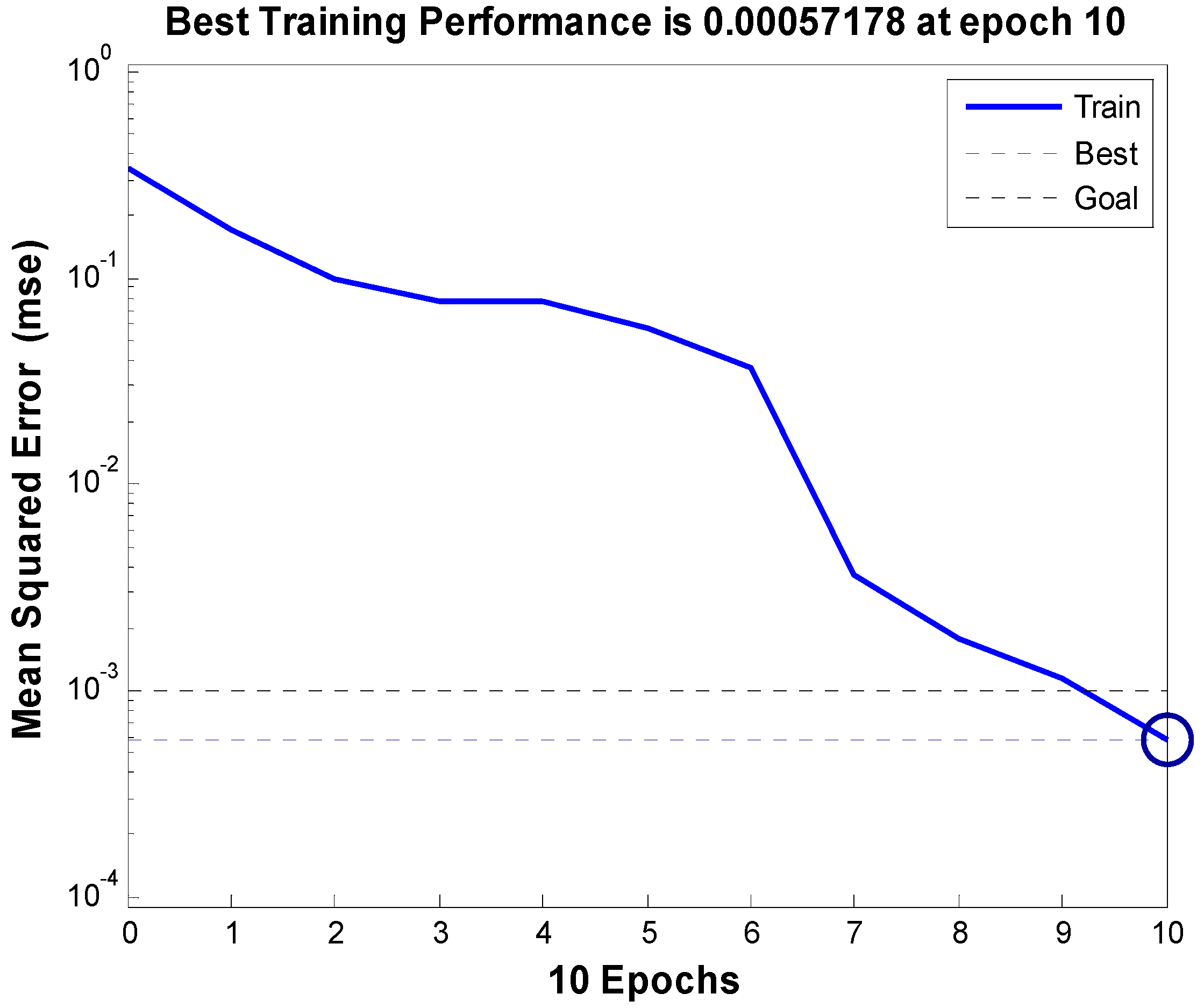
Firstly, the energy eigenvector and the expected outputs of the training samples are input in Table 2 to a BP neural network program. After 10 network learnings, the training meets the error requirement. The error convergence curve is shown in Figure 16. The abscissa is the number of learning, and the ordinate is the error sum of square. Then, the test samples are input to the fault diagnosis system. The method for processing the sample signal of the stator voltage and the rotor current is the same as the stator current. Last, the output results of the test sample and fault diagnosis are shown in Table 3 and Table 4, respectively.
In Table 3, ym represents the output of the neural network, the expected output of “normal” is (1,1,1)(y1 = 1; y2 = 1; y3 = 1); the expected output of “Fault 1” is (1,0,0); the expected output of “Fault 2” is (0,1,0); and the expected output of “Fault 3” is (0,0,1).
From the results in Table 3 and Table 4, it can be seen that the outputs of the fault state are accurate except the 22th group of the stator voltage sample. However, we still obtain an accurate fault diagnosis result after the logic unit. Compared with reference [24,25,26], which adopts the method of wavelet transform and neural network, the error rate can be reduced from 1% to 0.0298% by the logical unit proposed in this paper. Therefore, we can conclude that the fault diagnosis system established in this paper has the advantages of a high fault tolerance rate and a high accuracy of fault diagnosis.
5. Conclusions
- The field-circuit-movement coupling finite element model is established for the asynchronized high-voltage generator, which is used for simulating three kinds of faults (three phase short-circuit loss of excitation fault, three phase open-circuit loss of excitation fault, and three phase short-circuit fault on the stator side). The analysis result is a basis data for the symmetrical loss of excitation fault diagnosis of asynchronized high-voltage generators.
- The stator current maximum increase multiple of the asynchronized high-voltage generator at the moment of loss of excitation is related to the slip rate in the stable operation state before loss of excitation. The maximum stator current will rise with an increase of the slip rate.
- For asynchronized high-voltage generators, the stator current has a sharp increase at the moment of the three phase short-circuit loss of excitation fault and three phase short-circuit fault on the stator side, so it is necessary to adopt an effective fault diagnosis technique to eliminate the interference of the three phase short-circuit fault on the stator side.
- The symmetrical loss of excitation fault diagnosis system is established for the asynchronized high-voltage generator and the logic unit is introduced based on wavelet packet analysis and BP neural network. It can be concluded that this system effectively confirmed the interference of the three phase short-circuit fault on the stator side, accurately diagnosing the type of loss of the excitation fault, and improving the accuracy of fault diagnosis results.
Author Contributions
Firstly, Y.L. proposed a method of loss of excitation fault diagnosis, provided funding and led our research activity planning and execution. Then Y.G. applied software for simulation, maintained research data, validated this method, and prepared the writing-original draft. At last, J.Z., C.D. and S.H. conducted visualization and writing-review and editing.
Funding
This research was funded by National Natural Science Foundation of China (grant number: 5140070496).
Conflicts of Interest
The authors declare no conflict of interest.
References
- Ge, B.; Zhang, D.; Liang, Y. Powerformer and Its Recent Development. Trans. China Electr. Soc. 2005, 20, 26–30. [Google Scholar] [CrossRef]
- Zhang, H.; Xing, L.; Yan, W. Review on asynchronous generators under synchronous operation mode. North China Electr. Power 2000, 4, 48–50. [Google Scholar] [CrossRef]
- Yan, X.; Yu, S.; Zhu, L.; Li, M. Study of the static stability of asynchronized synchronous generators. Proc. CSEE 2002, 22, 89–93. [Google Scholar] [CrossRef]
- Chowdhury, M.A.; Hosseinzadeh, N.; Shen, W.X.; Pota, H.R. Comparative study on fault responses of synchronous generators and wind turbine generators using transient stability index based on transient energy function. Int. J. Electr. Power 2013, 51, 145–152. [Google Scholar] [CrossRef]
- Yang, S.; Liang, Z. Simulating study of operation action for asynchronized turbogenerators with excitation disappearance. Proc. CSEE 2002, 22, 104–108. [Google Scholar] [CrossRef]
- Li, C.; Ge, B.; Lv, Y.; Gu, F. Notice of Retraction Modeling and Simulation of Short-Circuit Loss of Excitation in Powerformer. In Proceedings of the 2009 Asia-Pacific Power and Energy Engineering Conference, Wuhan, China, 27–31 March 2009; pp. 2157–4839. [Google Scholar]
- Lv, Y.; Ge, B.; Tao, D.; Zhang, Z.; Lin, P. Analysis on magnetic field of extra high voltage generators asynchronously operated under Loss-of-Field condition. Proc. CSEE 2012, 32, 170–175. [Google Scholar] [CrossRef]
- Lv, Y.; Ge, B.; Tao, D.; Zhang, Z. Analysis and Determination of Protection Scheme of Powerformer under Loss of Excitation Based on the Wavelet Transform. Large Electr. Mach. Hydraul. Turbine 2010, 2, 21–24. [Google Scholar]
- Abedini, M.; Sanaye-Pasand, M.; Davarpanah, M. A Loss-of-Field Detection Relay Based on Rotor Signals Estimation. IEEE Trans. Power Deliv. 2018, 33, 779–788. [Google Scholar] [CrossRef]
- Mahamedi, B.; Zhu, J.G.; Hashemi, S.M. A Setting-Free Approach to Detecting Loss of Excitation in Synchronous Generators. IEEE Trans. Power Deliv. 2016, 31, 2270–2278. [Google Scholar] [CrossRef]
- Tambay, S.R.; Paithankar, Y.G. A New Adaptive Loss of Excitation Relay Augmented by Rate of Change of Reactance. In Proceedings of the IEEE Power Engineering Society General Meeting, San Francisco, CA, USA, 12–16 June 2005; pp. 1831–1835. [Google Scholar]
- Wu, L.; Yao, B.; Peng, Z.; Guan, Y. Fault Diagnosis of Roller Bearings Based on a Wavelet Neural Network and Manifold Learning. Appl. Sci. 2017, 7, 158. [Google Scholar] [CrossRef]
- Guo, S.; Yang, T.; Gao, W.; Zhang, C. A Novel Fault Diagnosis Method for Rotating Machinery Based on a Convolutional Neural Network. Sensors 2018, 18, 1429. [Google Scholar] [CrossRef] [PubMed]
- Cheng, S.; Wei, Q.; Zhao, H. Fault diagnosis system based on fuzzy-inference. Fuzzy Inf. Eng. 2012, 4, 51–61. [Google Scholar] [CrossRef]
- Immovilli, F.; Bianchini, C.; Lorenzani, E. Evaluation of Combined Reference Frame Transformation for Interturn Fault Detection in Permanent-Magnet Multiphase Machines. Ind. Electron. IEEE Trans. 2015, 62, 1912–1920. [Google Scholar] [CrossRef]
- Joghataie, A.; Torghabehi, O.O. Simulating Dynamic Plastic Continuous Neural Networks by Finite Elements. IEEE Trans. Neural Netw. Learn. Syst. 2014, 25, 1583–1587. [Google Scholar] [CrossRef] [PubMed]
- Precup, R.E.; Angelov, P.; Costa, B.S.J. An overview on fault diagnosis and nature-inspired optimal control of industrial process applications. Comput. Ind. 2015, 74, 75–94. [Google Scholar] [CrossRef]
- Ren, Z.; Huang, Q. New ways of fault detection in generators based on real wavelet transforms. Proc. CSEE 2002, 20, 58–60. [Google Scholar] [CrossRef]
- Anini, M.; Davarpanah, M.; Sanaye-Pasand, M. A Novel Approach to Detect the Synchronous Generator Loss of Excitation. IEEE Trans. Power Deliv. 2015, 30, 1429–1438. [Google Scholar] [CrossRef]
- Ho, S.L.; Li, H.L.; Fu, W.N.; Wong, H.C. A novel approach to circuit-field-torque coupled time stepping finite element modeling of electric machines. IEEE Trans. Magn. 2000, 36, 1886–1889. [Google Scholar] [CrossRef] [Green Version]
- Seman, S.; Niiranen, J.; Arkkio, A. Ride-Through Analysis of Doubly Fed Induction Wind-Power Generator under Unsymmetrical Network Disturbance. IEEE Trans. Power Syst. 2006, 21, 1782–1789. [Google Scholar] [CrossRef]
- Lv, Y.; Ge, B.; Li, C.; Zhang, Z. Dynamic Simulation of Powerformer under Loss of Excitation. In Proceedings of the 2009 Asia-Pacific Power and Energy Engineering Conference, Wuhan, China, 27–31 March 2009; pp. 2157–4839. [Google Scholar]
- Joksimović, G.M.; Penman, J. The detection of inter-turn short circuits in the stator windings of operating motors. IEEE Trans. Ind. Electron. 2000, 47, 1078–1084. [Google Scholar] [CrossRef]
- Mao, P.L.; Aggarwal, R.K. A Novel Approach to the Classification of the Transient Phenomena in Power Transformers Using Combined Wavelet Transform and Neural Network. IEEE Trans. Power Deliv. 2001, 16, 654–660. [Google Scholar] [CrossRef]
- Tiwari, V.K.; Umarikar, A.C.; Jain, T. Fast Amplitude Estimation of Harmonics Using Undecimated Wavelet Packet Transform and Its Hardware Implementation. IEEE Trans. Instrum. Meas. 2018, 67, 65–77. [Google Scholar] [CrossRef]
- Colak, I.; Bulbul, H.I.; Sagiroglu, S.; Sahin, M. Modeling a permanent magnet synchronous generator used in wind turbine and the realization of voltage control on the model with artificial neural networks. In Proceedings of the 2012 International Conference on Renewable Energy Research and Applications (ICRERA), Nagasaki, Japan, 11–14 November 2012; pp. 1–6. [Google Scholar] [CrossRef]
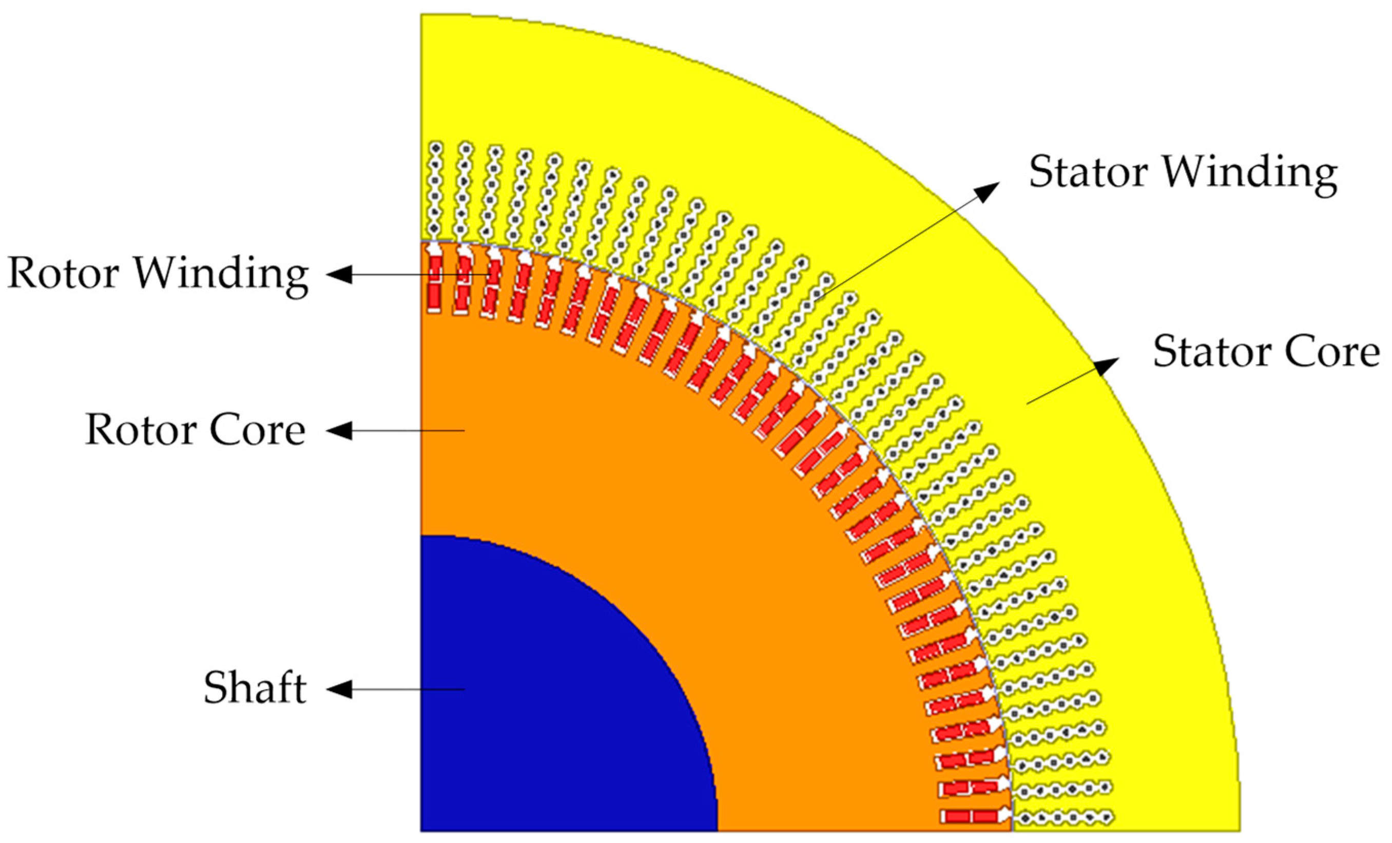
Figure 1.
Physical model of the asynchronized high-voltage generator.

Figure 2.
Equivalent circuit diagram of stator winding.

Figure 3.
Equivalent circuit diagram of rotor winding.

Figure 4.
The system of the asynchronized high-voltage generator.

Figure 5.
The simulation model of the asynchronized high-voltage generator under a loss of excitation.
Figure 5.
The simulation model of the asynchronized high-voltage generator under a loss of excitation.
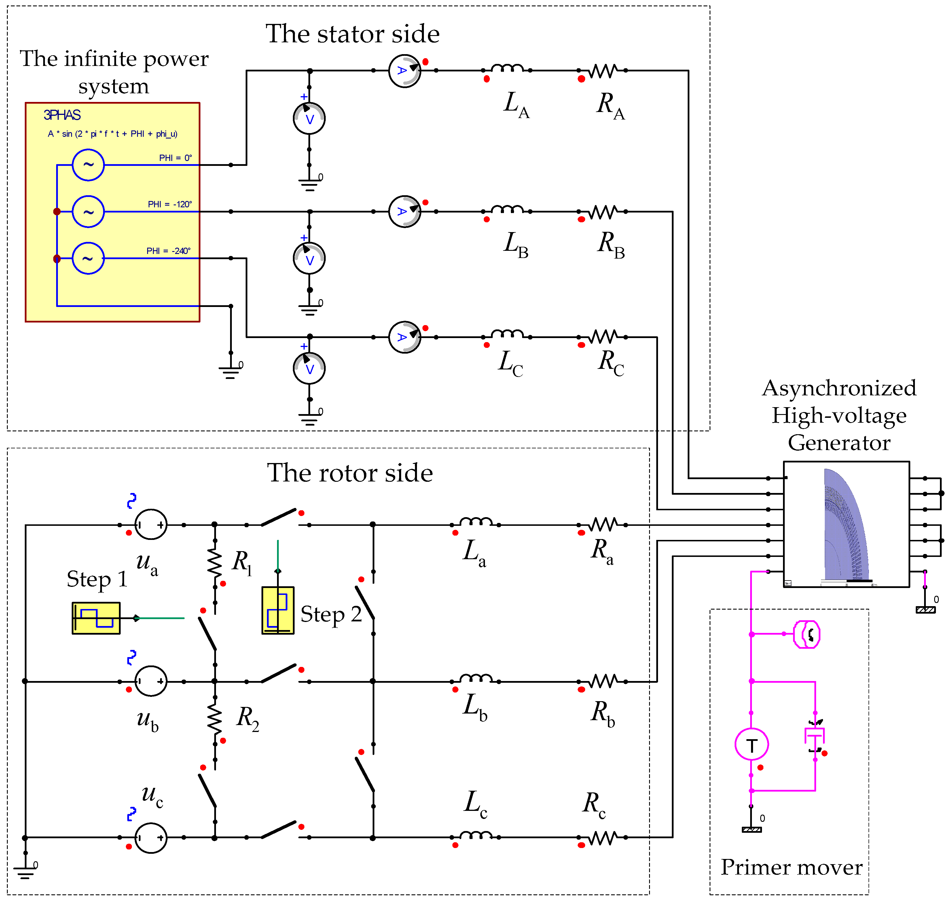
Figure 6.
Experiment of the asynchronized high-voltage generator for a loss of excitation.
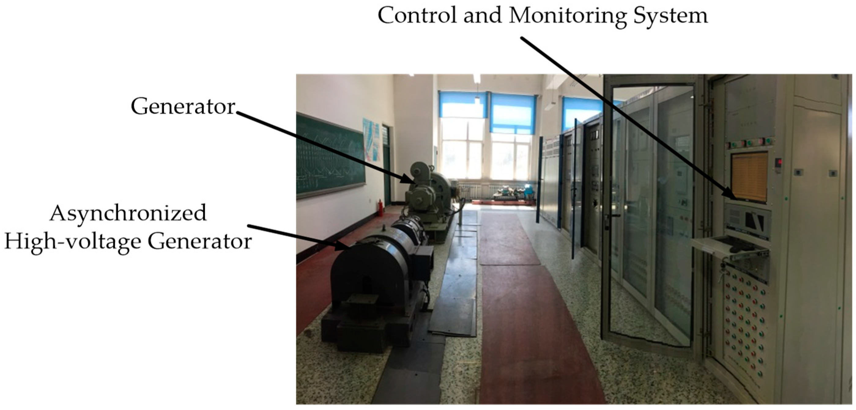
Figure 7.
The stator current and harmonic analysis under the three phase short-circuit loss of excitation: (a) Simulation results; (b) test results; (c) simulation results; (d) test results.
Figure 7.
The stator current and harmonic analysis under the three phase short-circuit loss of excitation: (a) Simulation results; (b) test results; (c) simulation results; (d) test results.

Figure 8.
The distributions of the magnetic field for the generator in normal operation and the three phase short-circuit loss of excitation in the subsynchronous operation state, when s is 0.08: (a) Normal operation; (b) three phase short circuit loss of excitation operation.
Figure 8.
The distributions of the magnetic field for the generator in normal operation and the three phase short-circuit loss of excitation in the subsynchronous operation state, when s is 0.08: (a) Normal operation; (b) three phase short circuit loss of excitation operation.
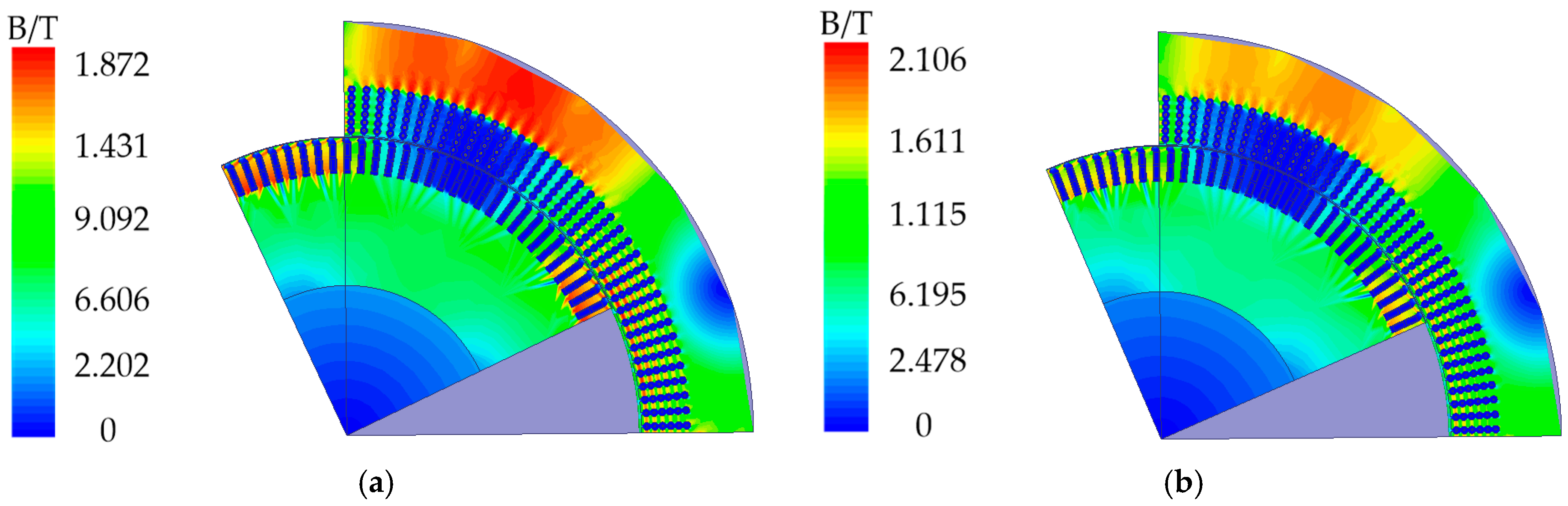
Figure 9.
The waveforms of electrical quantities after the three phase short-circuit loss of excitation in the subsynchronous operation state (s = 0.08): (a) Stator current; (b) stator induced voltage; (c) rotor current.
Figure 9.
The waveforms of electrical quantities after the three phase short-circuit loss of excitation in the subsynchronous operation state (s = 0.08): (a) Stator current; (b) stator induced voltage; (c) rotor current.

Figure 10.
The increase multiples of the stator current after the three phase short-circuit loss of excitation.
Figure 10.
The increase multiples of the stator current after the three phase short-circuit loss of excitation.
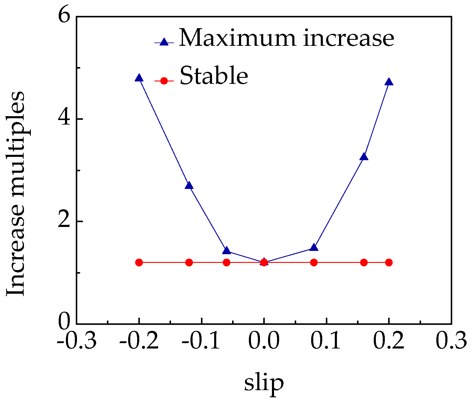
Figure 11.
The waveforms of electrical quantities after the three phase open-circuit loss of excitation in the subsynchronous operation state, when s is 0.08: (a) Stator current; (b) stator induced voltage; (c) rotor current.
Figure 11.
The waveforms of electrical quantities after the three phase open-circuit loss of excitation in the subsynchronous operation state, when s is 0.08: (a) Stator current; (b) stator induced voltage; (c) rotor current.

Figure 12.
The waveforms of electrical quantities after the stator three phase short-circuit fault in the subsynchronous operation state when s is 0.08: (a) Stator current; (b) stator induced voltage; (c) rotor current.
Figure 12.
The waveforms of electrical quantities after the stator three phase short-circuit fault in the subsynchronous operation state when s is 0.08: (a) Stator current; (b) stator induced voltage; (c) rotor current.
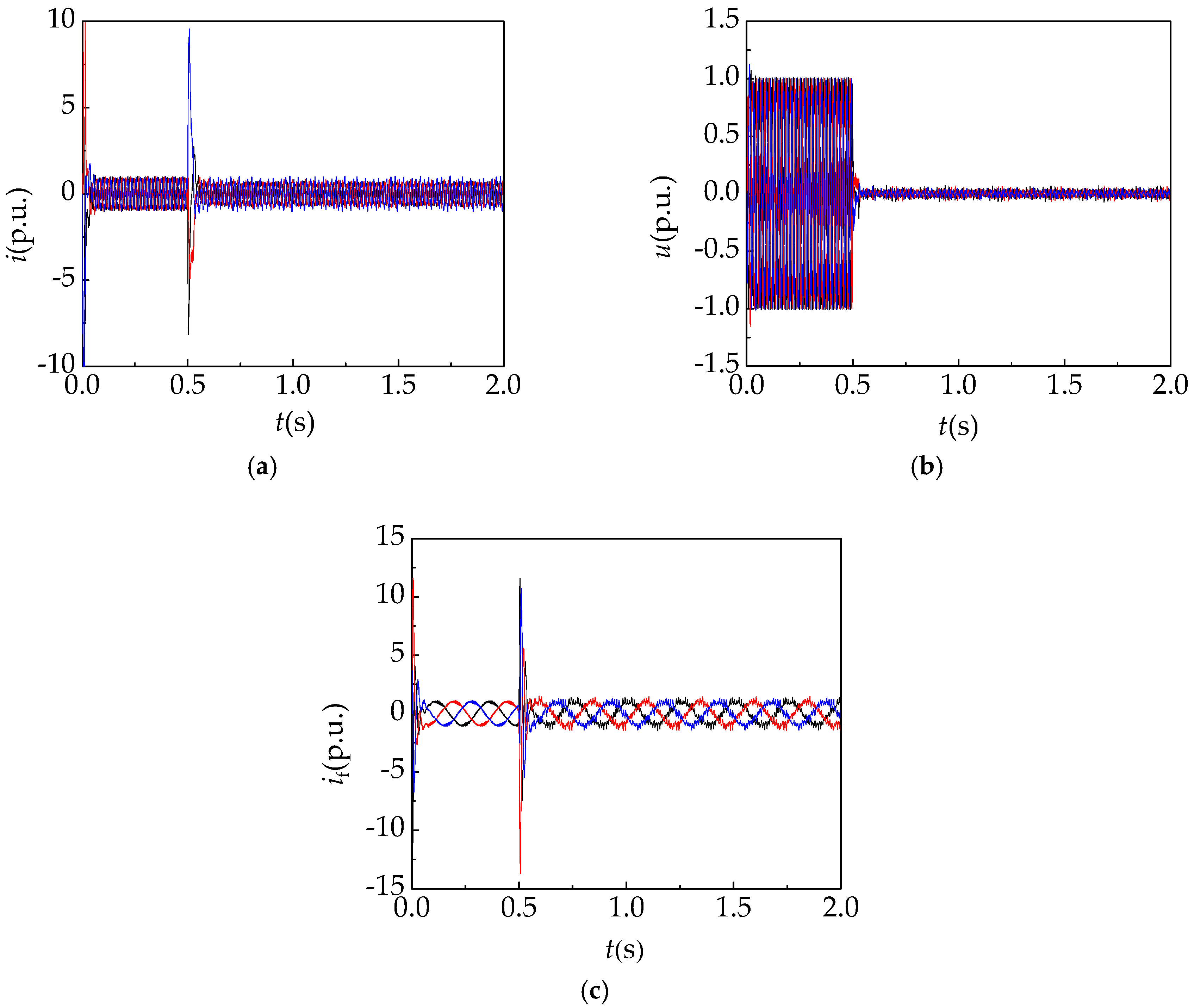
Figure 13.
Symmetrical loss of excitation fault diagnosis system for the asynchronized high-voltage generator.
Figure 13.
Symmetrical loss of excitation fault diagnosis system for the asynchronized high-voltage generator.
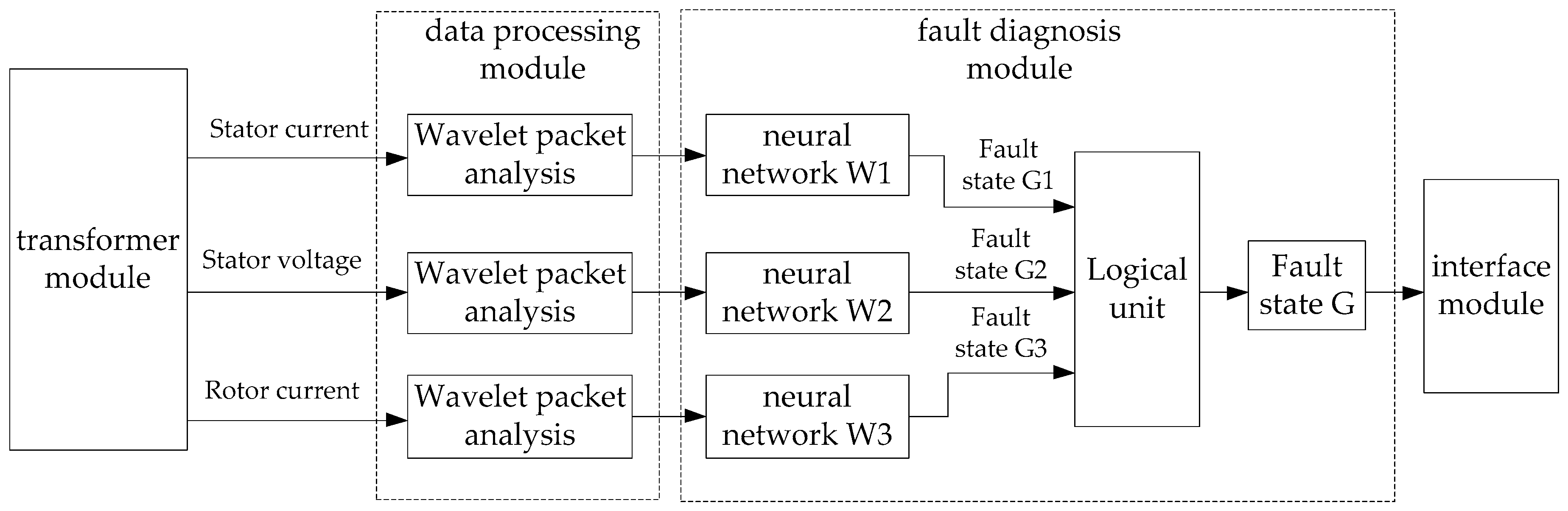
Figure 14.
Structure diagram of the three-layer wavelet packet decomposition.
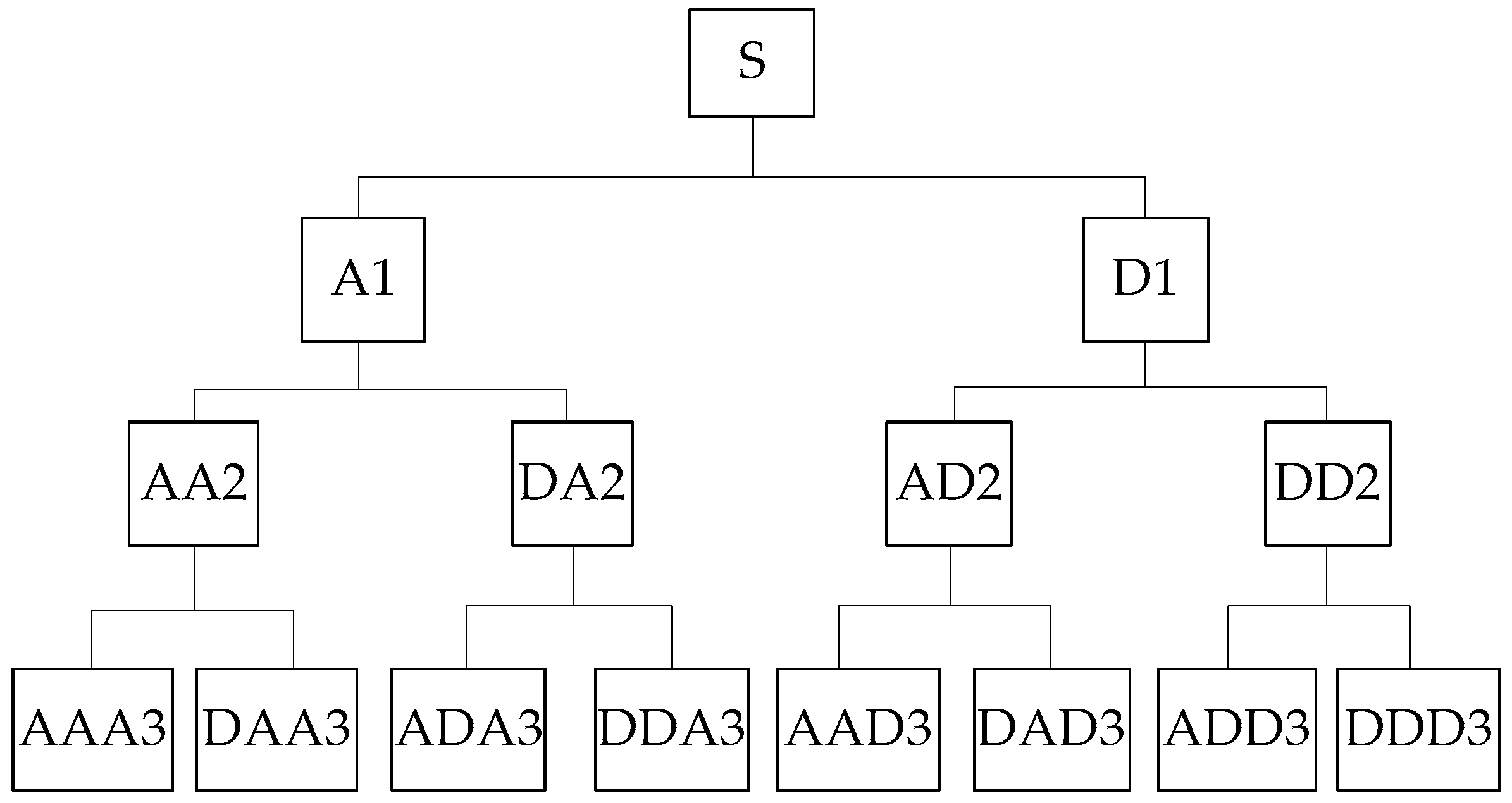
Figure 15.
The structure diagram of the logical unit.
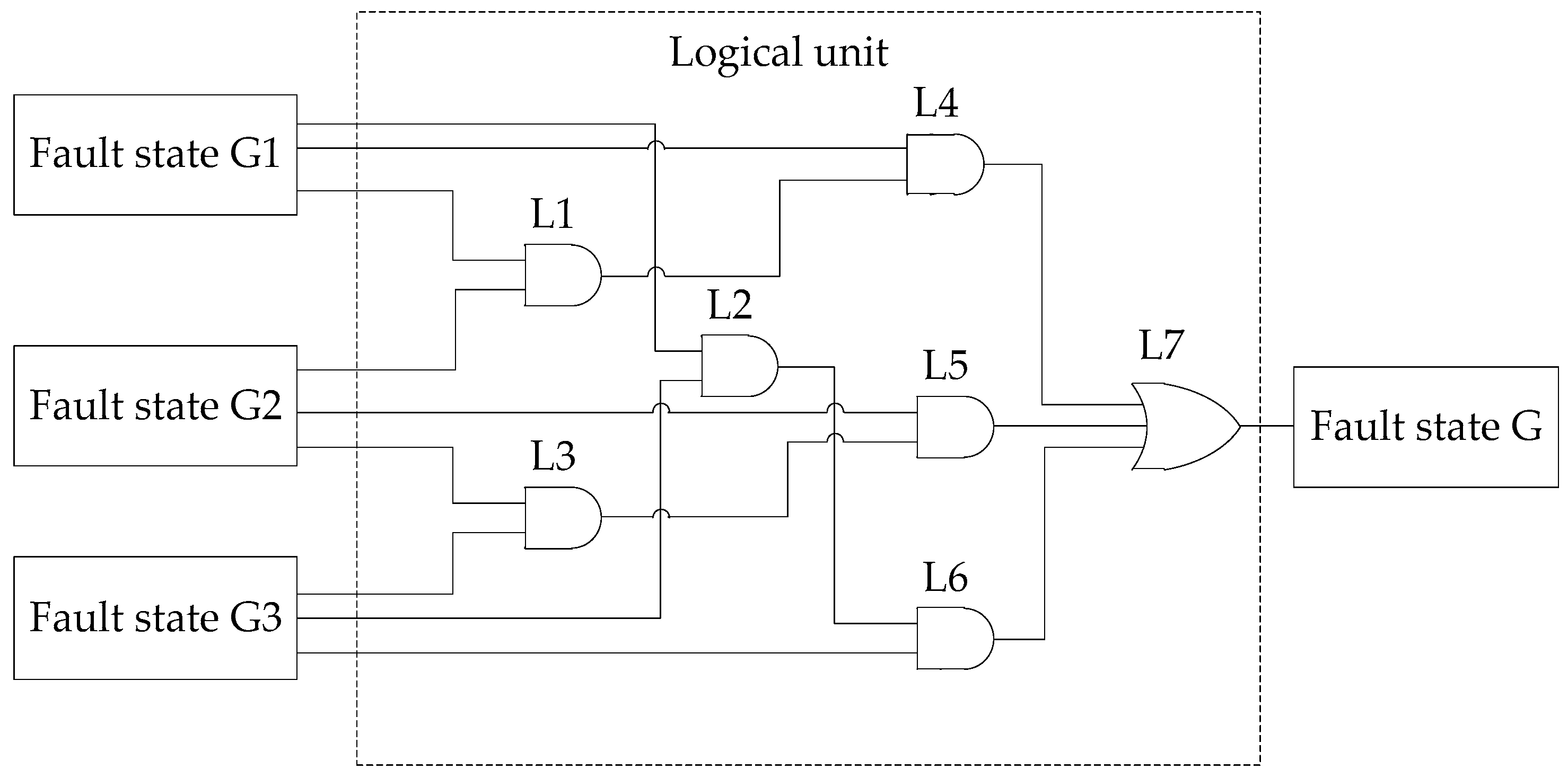
Figure 16.
Error convergence curve.

Table 1.
Basic generator parameters of the asynchronized high-voltage generator.
| Parameter | Value | Parameter | Value |
|---|---|---|---|
| Rated power | 130 kW | Rated voltage | 5 kV |
| Number of poles | 4 | Rated synchronous speed | 1500 r/min |
| Stator core outer diameter | 690 mm | Inner diameter of stator core | 500 mm |
| Rotor core outer diameter | 497 mm | Inner diameter of rotor core | 250 mm |
| Stator slot number | 144 | Stator per phase per slot | 12 |
| Rotor slot number | 120 | Rotor per phase per slot | 10 |
| Rated power factor | 0.8 | Three phase stator winding Y connection | |
Table 2.
The energy eigenvector of the stator current sample signals.
| Training Sample | |||||||||
|---|---|---|---|---|---|---|---|---|---|
| Sample | E0 | E1 | E2 | E3 | E4 | E5 | E6 | E7 | Fault State |
| T1 | 0.5162 | 0.3175 | 0.0318 | 0.0724 | 0.0161 | 0.0148 | 0.0197 | 0.0114 | Normal |
| T2 | 0.4961 | 0.3209 | 0.0309 | 0.0881 | 0.0129 | 0.0127 | 0.0246 | 0.0139 | Normal |
| T3 | 0.5024 | 0.3209 | 0.0399 | 0.0743 | 0.0146 | 0.0145 | 0.0210 | 0.0125 | Normal |
| T4 | 0.5749 | 0.2760 | 0.0383 | 0.0259 | 0.0058 | 0.0129 | 0.0442 | 0.0220 | Fault 1 |
| T5 | 0.6051 | 0.2957 | 0.0316 | 0.0217 | 0.0035 | 0.0064 | 0.0257 | 0.0103 | Fault 1 |
| T6 | 0.6085 | 0.3002 | 0.0309 | 0.0216 | 0.0035 | 0.0050 | 0.0215 | 0.0089 | Fault 1 |
| T7 | 0.5775 | 0.2814 | 0.0343 | 0.0201 | 0.0049 | 0.0154 | 0.0447 | 0.0218 | Fault 1 |
| T8 | 0.6051 | 0.2970 | 0.0322 | 0.0193 | 0.0035 | 0.0069 | 0.0260 | 0.0100 | Fault 1 |
| T9 | 0.5732 | 0.2878 | 0.0337 | 0.0186 | 0.0049 | 0.0152 | 0.0453 | 0.0214 | Fault 1 |
| T10 | 0.6189 | 0.2998 | 0.0318 | 0.0198 | 0.0034 | 0.0039 | 0.0167 | 0.0057 | Fault 2 |
| T11 | 0.6195 | 0.2982 | 0.0324 | 0.0205 | 0.0035 | 0.0037 | 0.0167 | 0.0056 | Fault 2 |
| T12 | 0.6198 | 0.2986 | 0.0322 | 0.0204 | 0.0033 | 0.0037 | 0.0163 | 0.0056 | Fault 2 |
| T13 | 0.6428 | 0.1730 | 0.0563 | 0.0753 | 0.0102 | 0.0114 | 0.0140 | 0.0171 | Fault 3 |
| T14 | 0.7350 | 0.1335 | 0.0351 | 0.0456 | 0.0045 | 0.0089 | 0.0214 | 0.0160 | Fault 3 |
| T15 | 0.7540 | 0.1173 | 0.0350 | 0.0440 | 0.0042 | 0.0095 | 0.0202 | 0.0159 | Fault 3 |
| Test Sample | |||||||||
| T16 | 0.5034 | 0.3178 | 0.0407 | 0.0804 | 0.0133 | 0.0122 | 0.0180 | 0.0142 | Normal |
| T17 | 0.5750 | 0.2761 | 0.0380 | 0.0243 | 0.0062 | 0.0144 | 0.0431 | 0.0230 | Fault 1 |
| T18 | 0.6046 | 0.2959 | 0.0323 | 0.0194 | 0.0036 | 0.0069 | 0.0269 | 0.0104 | Fault 1 |
| T19 | 0.5763 | 0.2949 | 0.0318 | 0.0181 | 0.0049 | 0.0138 | 0.0418 | 0.0184 | Fault 1 |
| T20 | 0.6192 | 0.2964 | 0.0329 | 0.0217 | 0.0040 | 0.0040 | 0.0161 | 0.0056 | Fault 2 |
| T21 | 0.6194 | 0.2995 | 0.0320 | 0.0197 | 0.0034 | 0.0038 | 0.0166 | 0.0057 | Fault 2 |
| T22 | 0.7896 | 0.0846 | 0.0353 | 0.0467 | 0.0038 | 0.0081 | 0.0198 | 0.0121 | Fault 3 |
| T23 | 0.7432 | 0.1235 | 0.0437 | 0.0613 | 0.0027 | 0.0024 | 0.0154 | 0.0078 | Fault 3 |
Table 3.
The output results of the test sample.
| Sample | Stator Current | Stator Voltage | Rotor Current | Expect Output | ||||||
|---|---|---|---|---|---|---|---|---|---|---|
| No. | y1 | y2 | y3 | y1 | y2 | y3 | y1 | y2 | y3 | y1,y2,y3 |
| T16 | 0.9988 | 0.9895 | 0.9896 | 1.0000 | 0.9800 | 0.9925 | 0.9323 | 0.9960 | 0.9771 | 1,1,1 |
| T17 | 0.9999 | 0.0005 | 0.0030 | 0.9937 | 0.0080 | 0.0057 | 1.0000 | 0.0000 | 0.0233 | 1,0,0 |
| T18 | 0.9991 | 0.0014 | 0.0001 | 0.9951 | 0.0104 | 0.0055 | 0.9635 | 0.0061 | 0.0000 | 1,0,0 |
| T19 | 1.0000 | 0.0010 | 0.0005 | 0.9998 | 0.0004 | 0.0106 | 1.0000 | 0.0000 | 0.0003 | 1,0,0 |
| T20 | 0.0408 | 0.9543 | 0.0015 | 0.1144 | 0.8203 | 0.0017 | 0.1522 | 0.9663 | 0.0273 | 0,1,0 |
| T21 | 0.0551 | 0.9281 | 0.0007 | 0.0886 | 0.8686 | 0.0017 | 0.0083 | 0.9953 | 0.0200 | 0,1,0 |
| T22 | 0.0016 | 0.0001 | 0.9953 | 0.9998 | 0.0000 | 0.9997 | 0.0111 | 0.0000 | 0.9617 | 0,0,1 |
| T23 | 0.0001 | 0.0438 | 0.9292 | 0.0020 | 0.0005 | 0.9945 | 0.0005 | 0.0000 | 0.9962 | 0,0,1 |
Table 4.
The output results of the fault diagnosis.
| Sample | Fault State G1 | Fault State G2 | Fault State G3 | Fault State G |
|---|---|---|---|---|
| T16 | Normal | Normal | Normal | Normal |
| T17 | Fault 1 | Fault 1 | Fault 1 | Fault 1 |
| T18 | Fault 1 | Fault 1 | Fault 1 | Fault 1 |
| T19 | Fault 1 | Fault 1 | Fault 1 | Fault 1 |
| T20 | Fault 2 | Fault 2 | Fault 2 | Fault 2 |
| T21 | Fault 2 | Fault 2 | Fault 2 | Fault 2 |
| T22 | Fault 3 | Error | Fault 3 | Fault 3 |
| T23 | Fault 3 | Fault 3 | Fault 3 | Fault 3 |
© 2018 by the authors. Licensee MDPI, Basel, Switzerland. This article is an open access article distributed under the terms and conditions of the Creative Commons Attribution (CC BY) license (http://creativecommons.org/licenses/by/4.0/).
Share and Cite
MDPI and ACS Style
Lv, Y.; Gao, Y.; Zhang, J.; Deng, C.; Hou, S. Symmetrical Loss of Excitation Fault Diagnosis in an Asynchronized High-Voltage Generator. Energies 2018, 11, 3054. https://doi.org/10.3390/en11113054
AMA Style
Lv Y, Gao Y, Zhang J, Deng C, Hou S. Symmetrical Loss of Excitation Fault Diagnosis in an Asynchronized High-Voltage Generator. Energies. 2018; 11(11):3054. https://doi.org/10.3390/en11113054
Chicago/Turabian StyleLv, Yanling, Yuting Gao, Jian Zhang, Chenmin Deng, and Shiqiang Hou. 2018. "Symmetrical Loss of Excitation Fault Diagnosis in an Asynchronized High-Voltage Generator" Energies 11, no. 11: 3054. https://doi.org/10.3390/en11113054
Note that from the first issue of 2016, this journal uses article numbers instead of page numbers. See further details here.