Voltage Harmonic Suppression by Means of Grid-Connected Converters Using only Local Measurements †


Department of Electrical Engineering, Eindhoven University of Technology, P.O. Box 513, 5600MB Eindhoven, The Netherlands
*
Author to whom correspondence should be addressed.
†
This paper is an extended version of our paper published in ‘2017 IEEE 8th International Symposium on Power Electronics for Distributed Generation Systems (PEDG)’.
Energies 2018, 11(10), 2515; https://doi.org/10.3390/en11102515
Submission received: 30 August 2018
/
Revised: 12 September 2018
/
Accepted: 17 September 2018
/
Published: 21 September 2018
(This article belongs to the Special Issue Operation and Control of Power Distribution Systems)
Abstract
:A single-phase grid-connected converter is considered in this paper in the presence of harmonic problems introduced non-linear loads. In order to compensate the harmonics caused by the loads, a local voltage support scheme is proposed. This is an added feature because its implementation is in parallel with a conventional current control method. Distinctively, the measurements of the grid or load current are not needed since the scheme is based on only local measurements. On top of a fundamental part for desired power injection, the converter output current comprises a harmonic part for compensation. Thus, the grid current harmonic distortion is minimized and the enhancement of the local voltage quality is achieved. A comprehensive model analysis indicates that the proposed strategy can help to attenuate harmonics of the local voltage without compromising on the quality of the fundamental current injection. Experimental results validate the effectiveness of the proposed control scheme. Moreover, the impact of grid frequency estimation error on the control strategy’s performance is quantified theoretically and experimentally.
1. Introduction
Power electronic converters have been widely applied as an interface between the public grid and sustainable energy sources (or loads) [1,2,3]. Due to the non-ideal properties of these converters, the grid is faced with voltage and current harmonics [3]. These harmonics can however be countered through control of dedicated power converters. Voltage harmonic compensation is mostly fulfilled by placing a converter in series with the distorting voltage source, where the converter generates a voltage to compensate for the voltage harmonics [4]. Current harmonic compensation is achieved by placing a converter in parallel with the harmonic current source, where the converter serves as a current source to compensate for the current harmonics [5]. The focus of this paper is on the harmonic compensation strategy applied in these shunt grid-connected converters.
The commonly called harmonic compensation strategies of a shunt grid-connected converter can be separated into three categories. The first category is focused on improving its immunity to harmonic disturbances coming from the grid and load and overcoming the non-linearities of the converter itself in order to inject sinusoidal current into the grid [6,7,8]. The second category is devoted to absorbing harmonics caused by polluting loads by acting as an active power filter (APF) [5]. The last category intends to sink harmonics introduced by local loads in addition to (bidirectionally) exchanging active power with the grid [9,10,11,12,13,14,15,16]. The case considered in this paper belongs to the last category: compensation of harmonics introduced by the non-linear loads in addition to active power regulation.
To achieve these two objectives in a shunt converter, traditionally control strategies require an additional measurement of the grid current [9] or the non-linear load current [10,11,12] for harmonic content detection and identification. Consequentially, the identified harmonic content is used for the reference formulation of the shunt converter output current. To this end, a current controller is designed with a bandwidth covering the frequency range of the harmonics to be compensated. In this type of strategy, the harmonic detection should have a high accuracy for good harmonic compensation performance. Moreover, an additional measurement of the grid current or the non-linear load current is necessary for this type of control strategy, which is not always practical, especially when there are multiple distributed loads. Therefore, harmonic compensation integrated in distributed generators (DGs) based on only local measurements is receiving increasing attention recently [13,14,15,16]. In this strategy the already-present measurement in the shunt grid-connected inverters, the local voltage that is conventionally used for grid synchronization, is additionally used for harmonic detection and compensation. Therefore, no measurement of the grid current or the load current is required. The primary functionality of a DG is the injection of desired synchronized power. Therefore, ideally, the added-on harmonic compensation should not impair the control accuracy of the power injection; however, it was not addressed [13,14] and hardly achieved [15]. In [16], a similar control architecture to [17,18] and this paper is used, but a voltage harmonic extractor was required for harmonic compensation, which adds up to the overall control complexity. Moreover, model analysis and control accuracy studies of such current-voltage hybrid control strategies are not available.
Motivated by the aforementioned issues, an add-on local voltage support strategy without compromising on the quality of power injection was proposed in [17] for existing grid-connected inverters. Since the add-on voltage support scheme works actively at the harmonic frequencies and the current control at the fundamental frequency, the proposed strategy induces no cross coupling between harmonic compensation and desired power injection and no harmonic extractor is needed as in [16]. According to the internal model principle (IMP) [19], to achieve zero-error reference tracking or disturbance rejection, the pattern of the reference or the disturbance should be taken into account during the controller design. This means that, when the IMP is applied in control of grid-connected converters, the frequency of the reference (or the disturbance) becomes essential for the controller design in order to achieve zero-error reference tracking or disturbance rejection. Since only harmonic disturbances are considered, all frequencies at play are the grid frequency and its multiples. Correspondingly, resonance filters [8,16,20,21] are commonly adopted as part of feedback controllers for grid-connected converters. Since resonance filters are notch filters and only have a very high gain in a narrow frequency band, zero-error tracking is barely achieved in practice when their resonance frequencies mismatch with the true harmonic frequencies [21]. In light of this, the control algorithm’s sensitivity to the grid frequency estimation error is also analyzed in this paper.
Since this paper’s focus is on add-on voltage harmonic compensation without using additional sensors, the improvement in the local voltage harmonic content is analyzed in this paper. Additionally, in contrast to all currently available publications on voltage support using only local measurements, the control accuracy of the converter output current is also studied in this paper. In order to quantify the performance of the proposed method, a comprehensive model analysis is performed and several sets of experiments have been carried out to validate the models and the analysis.
The organization of this paper is as follows. In Section 2, the structure of the proposed control strategy for a grid-connected converter is described and a model of the corresponding closed-loop system is derived. It is followed by a comprehensive analysis of the closed-loop model in order to quantify the add-on voltage harmonic attenuation in Section 3. This section also provides the discussion of the add-on harmonic compensation on the fundamental output current control accuracy is also provided, as well as a study on the control algorithm’s sensitivity to the frequency estimation error and a corresponding compensation strategy. The performance of the control scheme is investigated by experiments in Section 4. Discussion is performed in Section 5. Finally, conclusions are drawn and recommendations are given.
2. Proposed Control Scheme and System Modelling
2.1. Structure of the Proposed Control Scheme
The diagram of the proposed control scheme for a single-phase grid-connected converter system is shown in Figure 1. The system is comprised of five main parts: a direct-current (DC) voltage source, a single-phase converter, an LCL filter for the attenuation of switching-frequency harmonics, the local loads, and the grid. A relatively weak grid is assumed (with impedance in Figure 1) since in this type of grid the local voltage quality is mostly affected by harmonic distortion [22].
As indicated in Figure 1, the proposed control scheme contains two loops: one for current regulation and the other one for voltage support. The profile of the local voltage at the point of common connection (pcc) is used in both loops: in the first the phase of the local voltage is extracted via a phase-locked-loop (PLL) for the synchronization of the converter output current, and in the second it is used for compensating harmonics. The two set-points for this scheme are: the desired magnitude of the fundamental converter output current, denoted as , and the desired harmonic content of the local voltage, represented by which will normally be equal to zero.
To differentiate the actual grid frequency from the one assumed during the design of the controller, a couple of notations are introduced before elaborating on the controller design. The frequency used to design the proposed control scheme is called the estimated grid frequency, referred to as ; while the actual one of the utility grid voltage is denoted as .
2.2. Current Control
A proportional-resonance (PR) filter is applied for the Current Control block in Figure 1 in order to achieve zero-error reference tracking [17,21]. Its transfer function is given by
where is the proportional gain, denotes the resonance gain, and represents its resonance angular frequency. Since the current control is designed to regulate the fundamental component of the converter output current, we have
with being called the estimated grid angular frequency.
2.3. Voltage Support
The Voltage Support controller in this case is constructed by paralleling multiple basic resonance filter cells. Its overall transfer function is given by
where k is the order of the resonance filter cell for -harmonic tracking (or rejection), is the set of harmonic orders to be compensated, and is the individual gain for the resonance filter cell, whose transfer function is given by
Note that should be met here in order not to interfere with the fundamental current control in Section 2.2. Details and explanations follow in the next two sections.
2.4. System Open-Loop Model
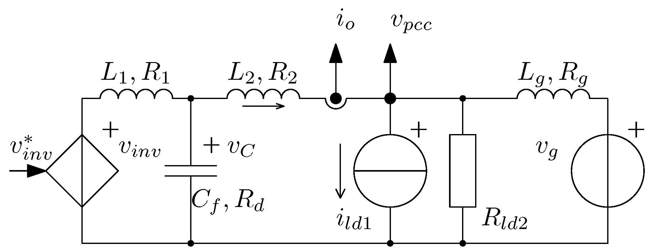
Ignoring the switching-frequency dynamics, the single-phase grid-connected converter in Figure 1 can be modelled as a linear plant with one control variable and two disturbances. Figure 2 shows the simplified diagram.
The dynamics of the converter output current and the local pcc voltage in Figure 2 are represented by
where , and represent the alternating current (ac) perturbations on the inverter output voltage, the grid voltage, and the non-linear load current, respectively. Both and are regarded as external disturbances to the model, and plays the role of the control action. Here to are the plant open-loop transfer functions (refer to (5) for the relation between input and output), which can be derived straightforwardly following a conventional modelling procedure of the grid-connected converter with LCL filter [23], hence their expressions are omitted in this paper.
2.5. System Closed-Loop Model
The system is governed by the feedback control algorithm as follows (see Figure 1)
where denotes the desired fundamental converter output current. Here and are the transfer functions of the current control in Section 2.2 and the voltage support in Section 2.3, respectively; they are given by
Analyzing the plant model in (5) and the controller model in (6), the resultant converter output current and the pcc voltage in the closed-loop system can be expressed as
The closed-loop transfer functions to are found to be
with being the system loop gain, found to be
3. Model Analysis for Harmonic Attenuation Effect Study
It is assumed that the system is stable since the focus of this paper is on the study of harmonic compensation accuracy. The parameters of the considered single-phase grid-connected converter system are shown in Table 1. The controller parameters are equal to those listed in Table 2, unless mentioned otherwise.
3.1. Fundamental Converter Output Current Regulation: , and
As can be seen from the closed-loop system model in (9), the converter output current is co-determined by the desired fundamental current , the grid voltage , the non-linear load current and the transfer functions , and . Equations (11), (13), and (15) indicate that in order to achieve zero-error fundamental reference tracking and zero-error fundamental disturbance (from the load and the grid) rejection, it is of vital importance to have and a finite value of .
Figure 3 shows the magnitude response of , and when the resonance filters are applied for voltage support, namely, by the substitution of (7) and (8) into (11), (13) and (15). It indicates that , and . In other words, when the grid frequency matches with the estimated one by , zero-error fundamental reference tracking and zero-error fundamental disturbance rejection is possible. Moreover, the transfer function of in (11) also explains why the voltage support loop should not resonate at the fundamental frequency, because it would make zero-error reference tracking impossible if . Hence, we should have in (3).
3.2. Add-on Voltage Harmonic Attenuation:
It is assumed that the non-linear load current is the only harmonic source of the system in Figure 1. Therefore, according to the closed-loop transfer function in (10), the harmonic content of the pcc voltage is determined by and the non-linear load harmonic content only. A rearrangement of the transfer function in (16) yields
where is the system’s closed-loop transfer function from to when the voltage support is removed from the controller (namely, when ). Here is the add-on harmonic attenuation transfer function by adding on . We have
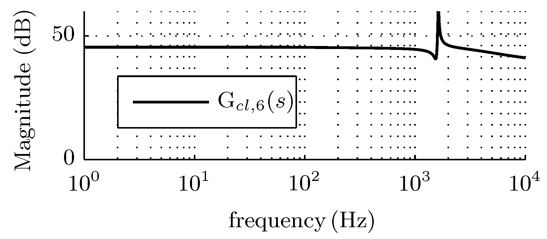
Figure 4 shows the magnitude response of . It can be noticed that when the non-linear load current has significant influence on the local voltage and the system has poor performance in rejecting it. Hereafter, the analysis of the add-on voltage support functionality will be based on the add-on harmonic attenuation transfer function .
Figure 5 shows the magnitude response of . It can be seen that with the proposed voltage support strategy, the pcc voltage harmonic attenuation functionality is added on by means of magnitude notches centered at the selected harmonic frequencies.
3.3. Sensitivity to Grid Frequency Estimation Error
As shown in Section 2, the controller is designed based on an estimated grid frequency quantity. Grid frequency estimation error is common and it deteriorates the notch filter performance, as mentioned in [21]. Therefore, this section discusses the impact of frequency estimation error on the harmonic attenuation performance. To quantify the impact of the grid frequency estimation error on the harmonic attenuation performance, an index, , is introduced. It refers to the normalized grid frequency estimation error, given by
Figure 6 shows the magnitude of as a function of the grid frequency estimation error , with . It can be seen that the harmonic attenuation effect is sensitive to the estimation error of the grid frequency and that the performance deteriorates when the error increases, as expected.
3.4. Compensation for Grid Frequency Estimation Error:
In theory zero-error harmonic attenuation is possible for the proposed control scheme since the resonance filters have infinite gain at the harmonic frequencies, independent of the proportional gain, . However, perfect harmonic attenuation is not always achieved in practice [21]. Figure 7 shows the magnitude of as a function of the grid frequency estimation with different values of , . As can be seen from Figure 7 that a smaller makes the system more sensitive to the grid frequency estimation error.
3.5. Discussion on the Application under a Grid with Frequency Change
Using a static frequency quantity to design the proposed controller under a grid with frequency change is not recommended because it will cause frequency estimation error, and consequently, will result in reduced harmonic attenuation, as illustrated in Section 3.3. This can be overcome by making the proposed control algorithm frequency-adaptive. The frequency adaptivity can be easily implemented in the proposed control algorithm by updating the estimated grid frequency on-line [24]. The grid frequency estimation can be incorporated in the phase lock loop (PLL) in the controller (referring to Figure 1) by advanced techniques [25].
4. Experimental Investigation
4.1. Setup Description
A laboratory setup was realized to investigate the experimental performance of the aforementioned control scheme in accordance with the system diagram shown in Figure 1. It consists of six main parts [17]: a DC power supply, a single-phase H-bridge converter, an LCL filter, a linear resistive load, a programmable current source acting as a non-linear load, a grid emulator Spitzenberger type DM 3000 and a dSPACE DS1104 real-time control system. The programmable current source is used to emulate a non-linear load that injects harmonic currents into the grid; its current waveform can be found in Figure 8, labelled . The nominal values of the system parameters are listed in Table 1. Note that unless mentioned otherwise, the controller is set according to Table 2.
A LeCroy Wavesurfer-44MXs-B oscilloscope was used to capture the experimental waveforms. The DS1104 system was applied to visualize the data acquired by the digital controller.
4.2. Discrete-Time Implementation
To avoid shifted resonance frequency problems, the resonance filters in the add-on voltage support loop in Section 2.3 are implemented by Forward Euler and Backward Euler integration methods with correction [26]. For a proper trade-off between implementation complexity and acceptable accuracy, only the first correction component is included. The resulting transfer function of the resonance filter cell in (4) in the z-domain is found to be
where is the sampling period of the implementation, and
4.3. Impact of Non-Linear Load on the Local Voltage Quality
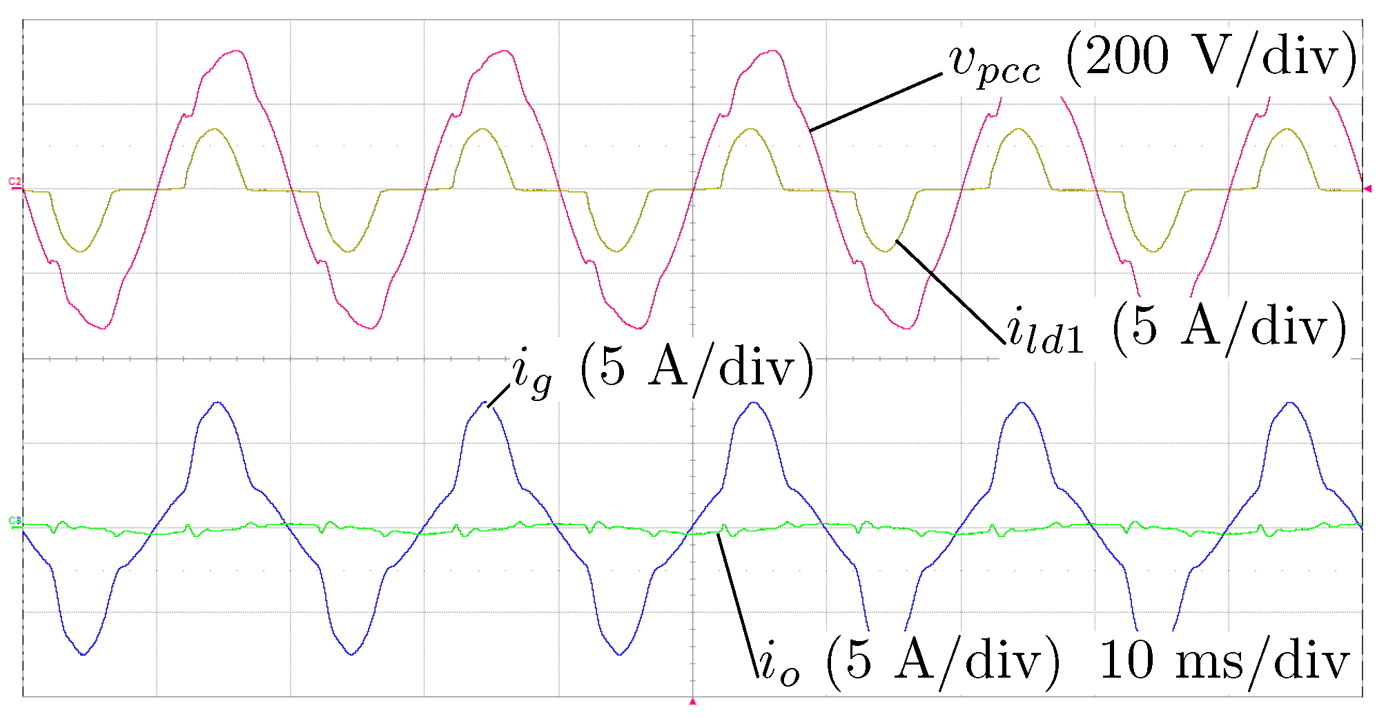
The impact of a non-liner load on the local voltage quality can be assessed in the case that all the converter switches are disabled. Therefore, only the filter components and in Figure 1 are passively involved in the power conversion. The non-linear load, Load 1, injects harmonic current into the point of common connection. Since the grid impedance is much smaller than the impedance of Load 2 (in the frequency range of interest), the harmonic current from Load 1 flows to the grid and makes the grid current and therefore also the pcc voltage distorted. Figure 8 shows the corresponding waveforms.
4.4. Validation of Voltage Support
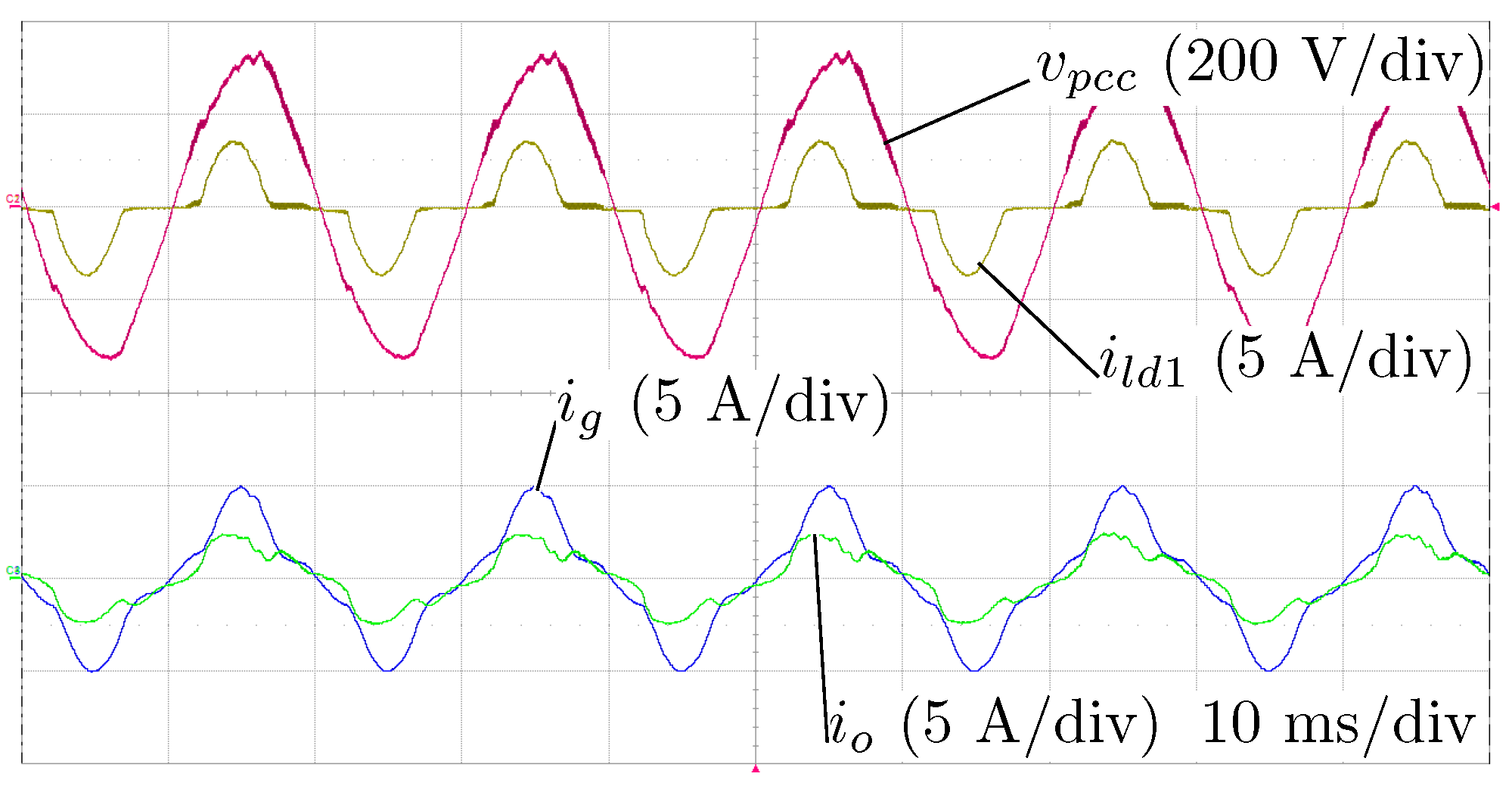
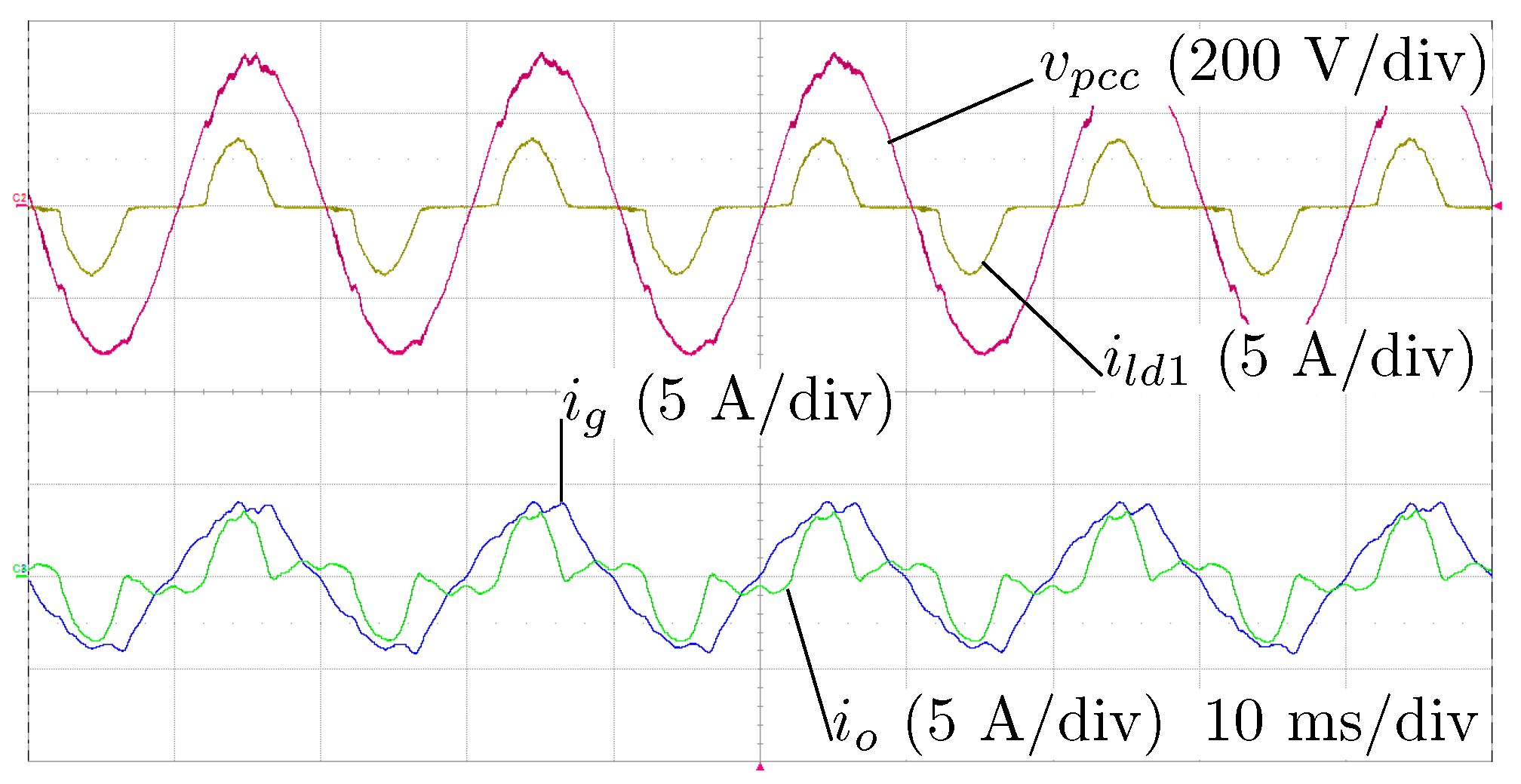
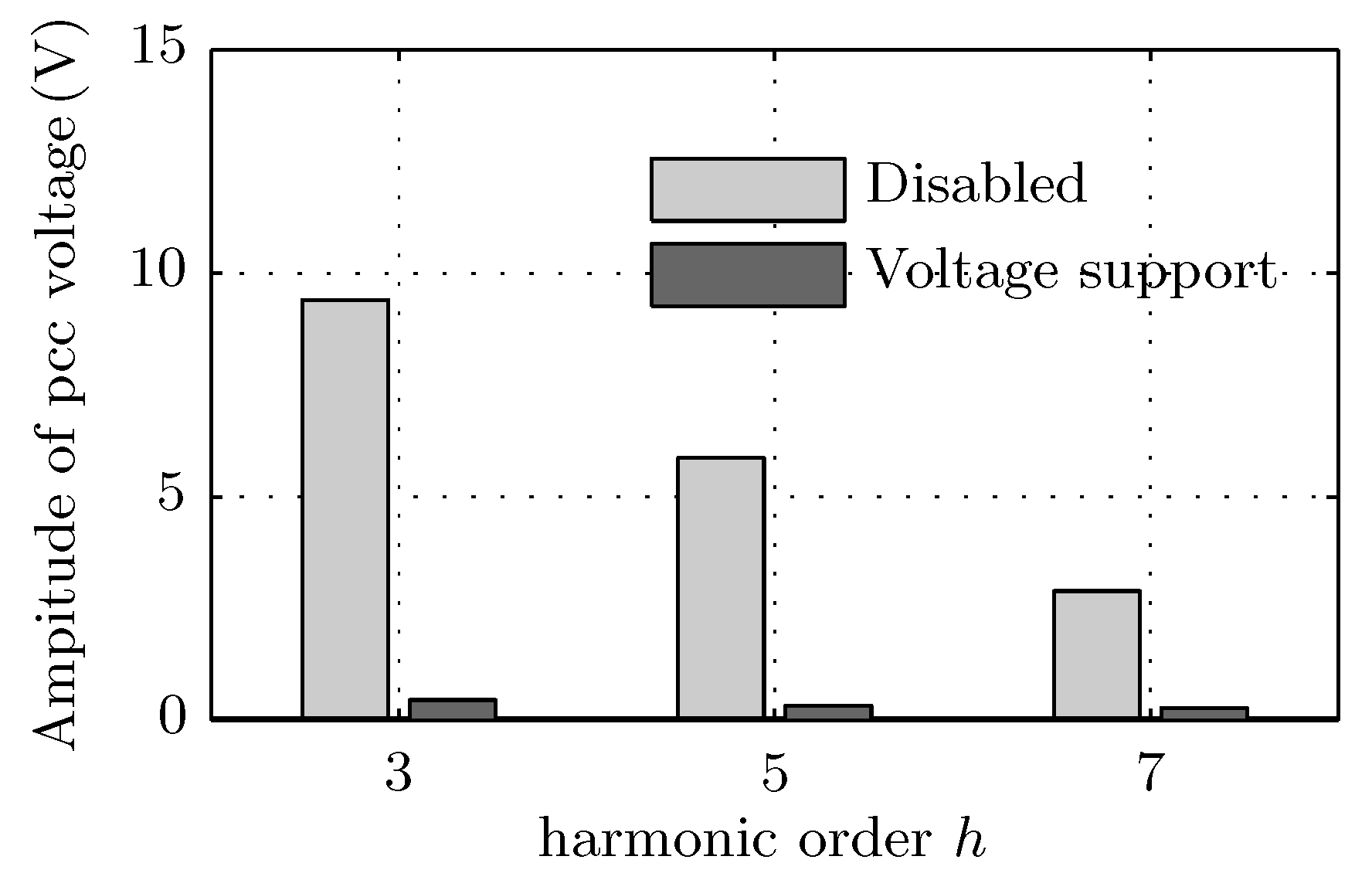
Figure 9 shows the waveforms when the current control is in operation and the voltage support is disabled. It can be seen that the local voltage and the grid current are still significantly distorted, compared to the case in Figure 8. This is expected since the system with the current control has poor performance in rejecting harmonic disturbances, as analyzed in Section 3.2. Figure 10 shows the waveforms when the voltage support loop is enabled. The local pcc voltage 3rd, 5th and 7th harmonic content in these two cases (in Figure 9 and Figure 10) is shown in Figure 11.
4.5. Validation of Fundamental Current Regulation
As mentioned earlier, one of the control objectives is to regulate the converter output current fundamental component. This section considers the performance of the control scheme for the fundamental converter output current regulation.
When the reference amplitude is zero, the converter is expected to operate as a harmonic compensator; when is not zero, the converter injects (or absorbs) active power from the grid side. Figure 12 shows the experimental waveforms when the converter is asked for harmonic compensation only, . Since the converter output current is distorted (non-sinusoidal on purpose of harmonic compensation), it is difficult to recognize its fundamental component (see Figure 10 and Figure 12). Therefore, a fast-Fourier-analysis is performed. Figure 13 shows the value of the amplitude of the converter output fundamental component as a function of its reference. It can be seen from Figure 13 that the converter output current fundamental component has a good match with its reference, and that it is independent of the harmonic compensation.
4.6. Sensitivity to Grid Frequency Estimation Error
In this section the control algorithm’s sensitivity to the grid frequency estimation error is investigated. It is worth mentioning that different from the model analysis in Section 3.3, in experiments the set frequency for the grid emulator is kept strictly constant at in order to have a consistent non-linear load current; the frequency estimation error is created by varying the estimated grid frequency . The results are shown in Figure 14. Consistent to the analysis in Figure 6, the system is sensitive to the grid frequency estimation error.
4.7. Compensation for Grid Frequency Estimation Error
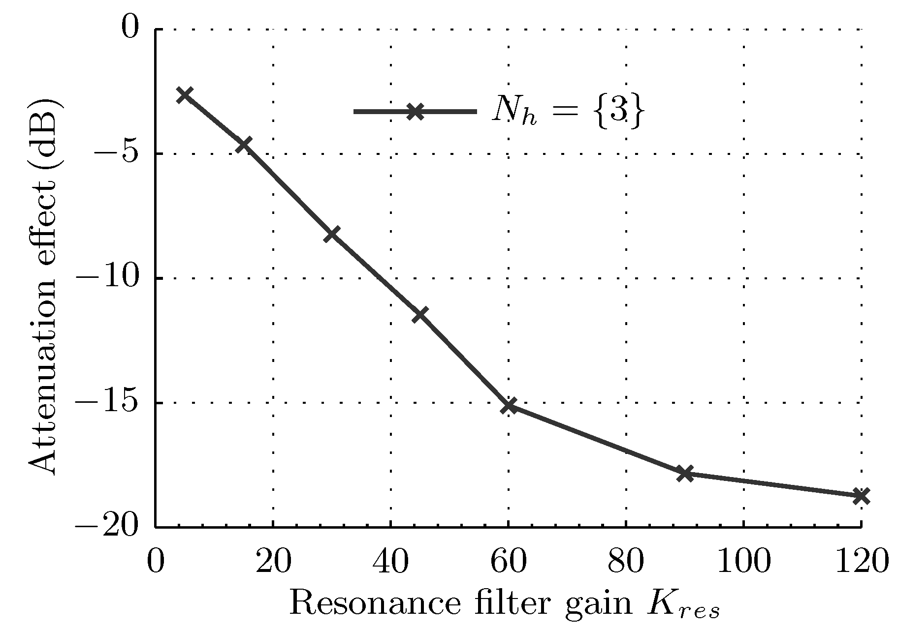
In this section the voltage harmonic attenuation effect is investigated as a function of the resonance filter gain. Figure 15 shows the experimental results when the resonance filter gain changes. In this set of tests the frequency used in the controller is while in order to create a grid frequency estimation error. The controller is set as .
5. Discussion
As demonstrated in Figure 8, local non-linear loads can pollute the grid, resulting in distorted grid current and impaired local voltage quality (under a weak grid). Conventional non-linear load harmonic compensation strategies for a shunt grid-connected converter additionally measure the grid or the load current for harmonic identification and compensation.
In order to compensate harmonics introduced by the non-linear loads using only existing local measurements around the point of common connection (pcc), an add-on local voltage support control scheme is proposed. Its implementation is in parallel with a conventional proportional-resonance current control method. The local pcc voltage profile is used not only for both traditional grid synchronization and add-on harmonic compensation. As a result, the measurements of the grid or the load current, which is necessary for conventional non-linear load harmonic compensation strategies, becomes unnecessary. In order to decouple the output current fundamental component regulation and the add-on voltage support, the controller is appropriately designed. The current regulation works actively at the fundamental frequency and the voltage support at the harmonic frequencies; therefore, the two loops are decoupled and hence the control accuracy of the fundamental current regulation is not compromised.
When the voltage support loop is disabled the local voltage quality is impaired since the system in Figure 1 (without voltage support) has poor performance in rejecting harmonic disturbances from the non-linear load, as analyzed in Figure 4 and demonstrated in Figure 9. When the voltage support loop is enabled, the system suppresses the harmonic disturbances on the local voltage, as demonstrated in Figure 10, which is consistent to the analysis in Section 3.2. Compared to the case in Figure 9, the grid current in Figure 10 becomes close to sinusoidal and the peak distortion is decreased. The harmonic analysis in Figure 11 further validates the benefit of using the add-on voltage support strategy. It shows that the local voltage harmonic content at selected frequencies is decreased compared to when the voltage-support is disabled, which has a good agreement with the analysis in Figure 5.
Next, the control strategy’s performance of tracking the fundamental output current reference is checked. As shown in Figure 10 and Figure 12, on top of harmonic compensation, the converter output current fundamental component can be regulated independently. The harmonic analysis in Figure 13 quantifies the performance and it is shown that the converter output current fundamental component tracks its reference well, which is expected according to the analysis in Figure 3.
Moreover, the sensitivity of the add-on voltage support strategy’s performance to the grid frequency estimation error is studied and quantified. Consistent to the model analysis in Figure 6, the experimental results in Figure 14 demonstrate that the voltage harmonic attenuation effect is highly dependent on the frequency estimation error, and the less the error, the better the attenuation. Both the model analysis in Figure 7 and experimental results in Figure 15 suggest that a large resonance filter gain helps to compensate for the frequency estimation error. As shown in Figure 14, zero-error harmonic attenuation is not fully achieved in the experiments even when the estimated frequency is identical to the grid emulator set-point frequency. This can be explained by two factors. The first one is the imperfect numerical implementation of the resonance filter in (23). Secondly, the grid emulator’s frequency is not perfectly stabilized at the set-point but has a certain precision. These two factors put limitations on practical zero-error harmonic rejection. Besides, in the experiments the best harmonic attenuation is seen when the estimation error is around (when ). This is explained by the inaccuracy of the grid emulator. A one-minute test showed that the grid emulator frequency varied between and even though its set-point was .
6. Conclusions
In this paper an add-on voltage support control scheme is proposed that compensates for the harmonics introduced by local non-linear loads. Its main advantage is that the measurements of the grid or load current, which is necessary in conventional strategies, is not necessary in the proposed scheme. In this way, existing grid-connected inverters can be upgraded through only a change of software to provide local voltage support. Moreover, compared to recent voltage support strategies using only local measurements, the proposed control strategy does not compromise on the quality of the fundamental output current regulation, which is viewed as the primary functionality of grid-connected inverters in distributed generator applications.
Consistent with the add-on voltage harmonic attenuation model analysis, the harmonic content on the local voltage was significantly attenuated in experiments when the scheme was applied. Precise regulation of the fundamental output current was achieved in experiments. This is expected because the voltage harmonic compensation control loop has no effect on the fundamental current regulation, as explained by the model analysis for the harmonic attenuation effect study.
On top of illustration and demonstration of the proposed control scheme’s effectiveness, a sensitivity study was carried out in this paper. Theoretically, zero-error reference tracking and zero-error disturbance rejection are possible with the proposed scheme. However, resonance filters are notch filters and they are sensitive to the frequency estimation error. Consistent with the sensitivity analysis, experiments confirm that the performance of harmonic compensation deteriorates dramatically when the difference between the true and estimated grid frequency increases. As indicated by the model analysis, reducing the grid frequency estimation error is seen as means to improve the control algorithm’s performance with respect to harmonic attenuation. Alternatively, in the presence of an inevitable grid frequency estimation error increasing the filter gain has been shown analytically and experimentally effective for the harmonic attenuation effect enhancement.
In conclusion, a proposed add-on voltage harmonic suppression scheme for a single-phase grid-connected converter system is discussed in this paper. An analytical model of the system is derived in order to illustrate the working principle of the scheme; additionally, the model is used to quantify the sensitivity of the scheme and accordingly a compensation strategy is raised. The experiments confirm the effectiveness and the sensitivity study of the proposed control scheme.
Author Contributions
Conceptualization Y.Z., M.A.M.H. and J.L.D.; Review & Supervision, M.G.L.R., M.A.M.H. and J.L.D.; Investigation & Writing, Y.Z.
Funding
This project has received funding from the Electronic Components and Systems for European Leadership Joint Undertaking under grant agreement No 737434. This Joint Undertaking receives support from the European Unions Horizon 2020 research and innovation programme and Germany, Slovakia, Netherlands, Spain, Italy.
Conflicts of Interest
The authors declare no conflict of interest.
Abbreviations
The following abbreviations are used in this manuscript:
| APF | Active power filter |
| DG | Distributed generators |
| IMP | Internal model principle |
| PR | Proportional resonance |
| DC | Direct current |
| PLL | Phase lock loop |
| pcc | Point of common connection |
| FFT | Fast Fourier Transformation |
| ac | alternating current |
References
- Hossain, M.A.; Pota, H.R.; Issa, W.; Hossain, M.J. Overview of AC microgrid controls with inverter-interfaced generations. Energies 2017, 10, 1300. [Google Scholar] [CrossRef]
- Karimi-Ghartemani, M. Universal integrated synchronization and control for single-phase DC/AC converters. IEEE Trans. Power Electron. 2015, 30, 1544–1557. [Google Scholar] [CrossRef]
- Tareen, W.; Aamir, M.; Mekhilef, S.; Nakaoka, M.; Seyedmahmoudian, M.; Horan, B.; Memon, M.; Baig, N. Mitigation of power quality issues due to high penetration of renewable energy sources in electric grid systems using three-phase APF/STATCOM technologies: A review. Energies 2018, 11, 1491. [Google Scholar] [CrossRef]
- Javadi, A.; Hamadi, A.; Woodward, L.; Al-Haddad, K. Experimental Investigation on a hybrid series active power compensator to improve power quality of typical households. IEEE Trans. Ind. Electron. 2016, 63, 4849–4859. [Google Scholar] [CrossRef]
- Fang, J.; Xiao, G.; Yang, X.; Tang, Y. Parameter design of a novel series-parallel-resonant LCL filter for single-phase half-bridge active power filters. IEEE Trans. Power Electron. 2017, 32, 200–217. [Google Scholar] [CrossRef]
- Zhao, Q.; Ye, Y.; Xu, G.; Zhu, M. Improved repetitive control scheme for grid-connected inverter with frequency adaptation. IET Power Electron. 2016, 5, 883–890. [Google Scholar] [CrossRef]
- Almeida, P.M.D.; Duarte, J.L.; Ribeiro, P.F.; Barbosa, P.G. Repetitive controller for improving grid-connected photovoltaic systems. IET Power Electron. 2014, 7, 1466–1474. [Google Scholar] [CrossRef] [Green Version]
- Castilla, M.; Miret, J.; Matas, J.; Vicuna, L.G.D.; Guerrero, J.M. Control design guidelines for single-phase grid-connected photovoltaic inverters with damped resonant harmonic compensators. IEEE Trans. Ind. Electron. 2009, 56, 4492–4501. [Google Scholar] [CrossRef]
- Trinh, Q.N.; Lee, H.H. An enhanced grid current compensator for grid-connected distributed generation under nonlinear loads and grid voltage distortions. IEEE Trans. Ind. Electron. 2014, 61, 6528–6537. [Google Scholar] [CrossRef]
- Bonaldo, J.P.; Paredes, H.K.M.; Pomilio, J.A. Control of single-phase power converters connected to low-voltage distorted power systems with variable compensation objectives. IEEE Trans. Power Electron. 2016, 31, 2039–2052. [Google Scholar] [CrossRef]
- Chilipi, R.R.; Sayari, N.A.; Beig, A.R.; Hosani, K.A. A multitasking control algorithm for grid-connected inverters in distributed generation applications using adaptive noise cancellation filters. IEEE Trans. Energy Convers. 2016, 31, 714–727. [Google Scholar] [CrossRef]
- Chen, X.; Dai, K.; Xu, C.; Peng, L.; Zhang, Y. Harmonic compensation and resonance damping for SAPF with selective closed-loop regulation of terminal voltage. IET Power Electron. 2017, 10, 619–629. [Google Scholar] [CrossRef]
- Li, Y.W.; He, J. Distribution system harmonic compensation methods: an overview of DG-interfacing inverters. IEEE Ind. Electron. Mag. 2014, 8, 18–31. [Google Scholar] [CrossRef]
- Brusco, G.; Burgio, A.; Menniti, D.; Motta, M.; Pinnarelli, A.; Sorrentino, N. A repetitive-based control for a single-phase shunt active power filter for harmonic voltage compensation. In Proceedings of the 2016 IEEE 16th International Conference on Environment and Electrical Engineering (EEEIC), Florence, Italy, 7–10 June 2016. [Google Scholar]
- D’Arco, S.; Ochoa-Gimenez, M.; Piegari, L.; Tricoli, P. Harmonics and interharmonics compensation with active front-End converters based only on local voltage measurements. IEEE Trans. Ind. Electron. 2017, 64, 796–805. [Google Scholar] [CrossRef]
- Zhao, X.; Meng, L.; Xie, C.; Guerrero, J.M.; Wu, X.; Vasquez, J.C.; Savaghebi, M. A voltage feedback based harmonic compensation strategy for current-controlled converters. IEEE Trans. Ind. Appl. 2017, 99, 2616–2627. [Google Scholar] [CrossRef]
- Zhang, Y.; Hendrix, M.A.M.; Roes, M.G.L.; Duarte, J.L. Grid-connected converters with voltage support using only local measurements. In Proceedings of the IEEE 8th International Symposium on Power Electronics for Distributed Generation Systems (PEDG), Florianopolis, Brazil, 17–20 April 2017. [Google Scholar]
- Zhang, Y.; Roes, M.G.L.; Hendrix, M.A.M.; Duarte, J.L. Stability analysis of grid-connected converters with add-on voltage support functionality using repetitive control. In Proceedings of the IEEE 10th International Power Electronics and Motion Control Conference (IPEMC-ECCE Asia), Niigata, Japan, 20–24 May 2018. [Google Scholar]
- Francis, B.A.; Wonham, W.M. The internal model principle of control theory. Automatica 1976, 12, 457–465. [Google Scholar] [CrossRef]
- Oruganti, H.; Dash, S.; Nallaperumal, C.; Ramasamy, S.; Oruganti, H.; Dash, S.S.; Nallaperumal, C.; Ramasamy, S. A proportional resonant controller for suppressing resonance in grid tied multilevel inverter. Energies 2018, 11, 1024. [Google Scholar] [CrossRef]
- Yang, Y.; Zhou, K.; Blaabjerg, F. Enhancing the frequency adaptability of periodic current controllers with a fixed sampling rate for grid-connected power converters. IEEE Trans. Power Electron. 2016, 31, 7273–7285. [Google Scholar] [CrossRef]
- Mastromauro, R.A.; Liserre, M.; Kerekes, T.; Dell’Aquila, A. A single-phase voltage-controlled grid-connected photovoltaic system with power quality conditioner functionality. IEEE Trans. Ind. Electron. 2009, 56, 4436–4444. [Google Scholar] [CrossRef]
- Zhang, Y.; Hendrix, M.; Roes, M.G.L.; Duarte, J.; Lomonova, E. Voltage harmonics suppression add-on functionality without additional sensors for existing grid-connected inverters. In Proceedings of the 19th European Conference on Power Electronics and Applications (EPE’17 ECCE-Europe), Warsaw, Poland, 11–14 September 2017. [Google Scholar]
- Herrán, M.A.; Fischer, J.R.; González, S.A.; Judewicz, M.G.; Carugati, I.; Carrica, D.O. Repetitive control with adaptive sampling frequency for wind power generation systems. IEEE J. Emerg. Sel. Top. Power Electron. 2014, 2, 58–69. [Google Scholar] [CrossRef]
- Xiao, F.; Dong, L.; Li, L.; Liao, X. A frequency-fixed SOGI-based PLL for single-phase grid-connected converters. IEEE Trans. Power Electron. 2017, 32, 1713–1719. [Google Scholar] [CrossRef]
- Yepes, A.G.; Freijedo, F.D.; Lopez, O.; Doval-Gandoy, J. High-performance digital resonant controllers implemented with two integrators. IEEE Trans. Power Electron. 2011, 26, 563–576. [Google Scholar] [CrossRef]
Figure 1.
Diagram of the proposed control scheme for a single-phase grid-connected converter system.
Figure 1.
Diagram of the proposed control scheme for a single-phase grid-connected converter system.
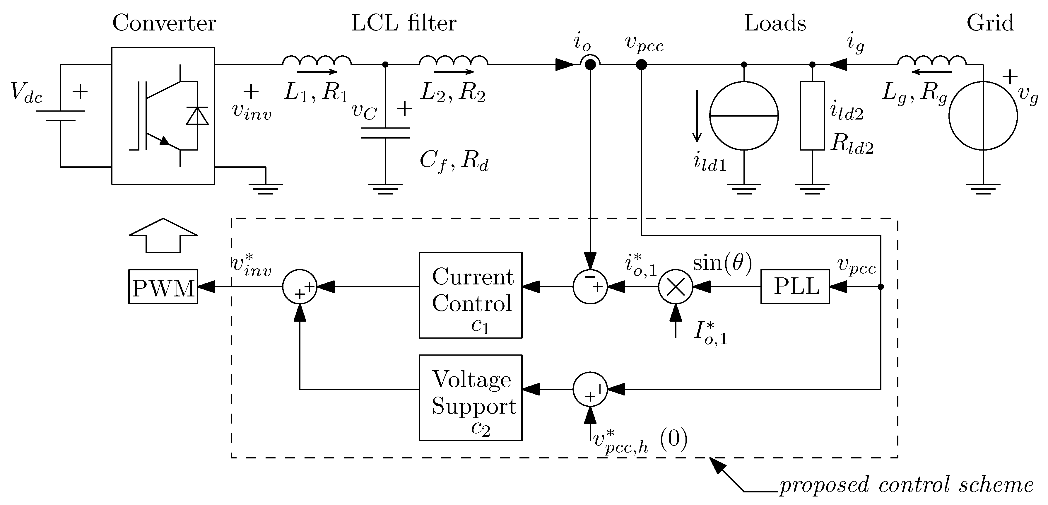
Figure 2.
Simplified diagram of the grid-connected converter with local loads.

Figure 3.
Magnitude response of , and .
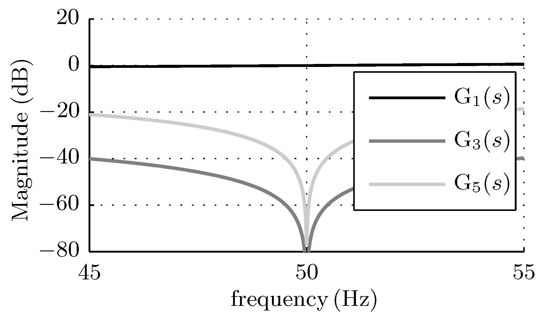
Figure 4.
Magnitude response of .

Figure 5.
Magnitude response of .
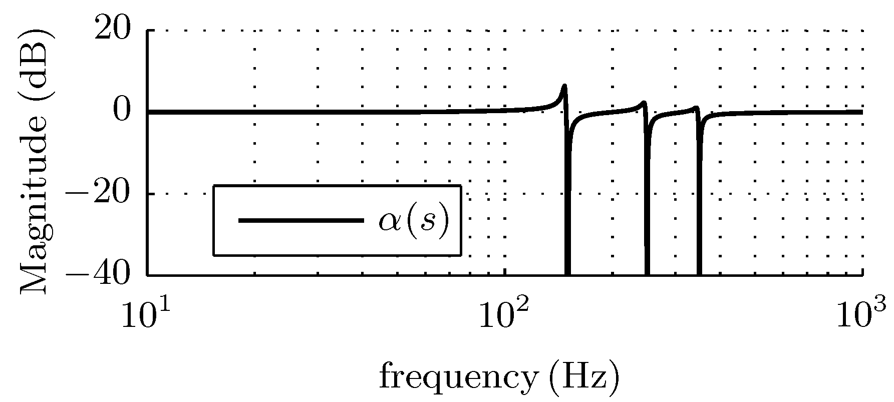
Figure 6.
Magnitude of as a function of the grid frequency estimation error , .
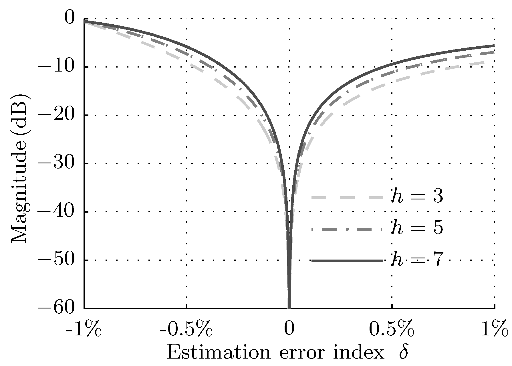
Figure 7.
Magnitude of with different values of , and .
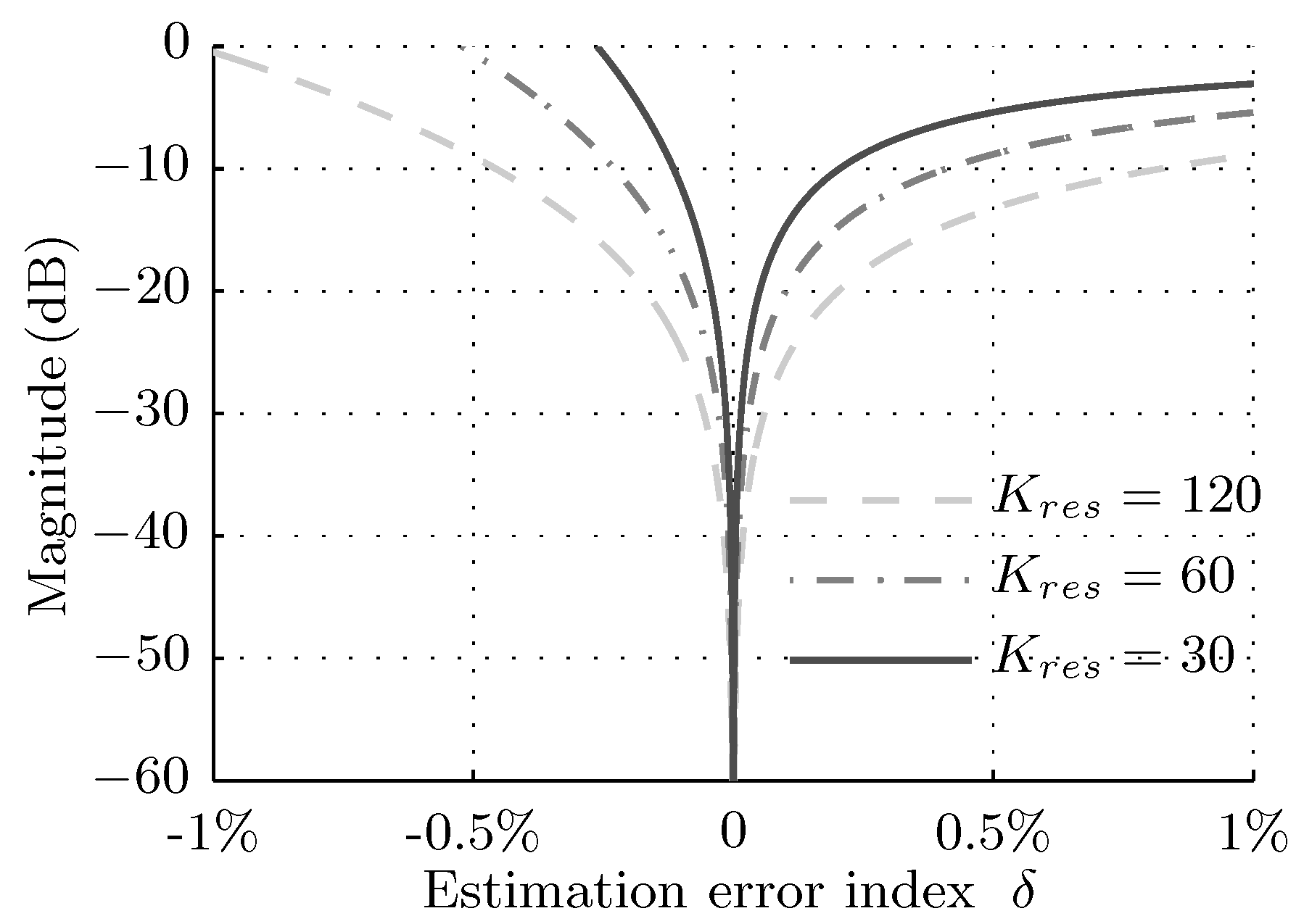
Figure 8.
Experimental waveforms when the converter operation is disabled; from the top to the bottom are the pcc voltage , the non-linear load current , the grid current and the converter output current .
Figure 8.
Experimental waveforms when the converter operation is disabled; from the top to the bottom are the pcc voltage , the non-linear load current , the grid current and the converter output current .

Figure 9.
Experimental results when the voltage support loop is not in operation, .

Figure 10.
Experimental results when the voltage support loop is enabled, .

Figure 11.
Comparison of the local voltage harmonic content between when the proposed voltage support is disabled and when it is in operation.
Figure 11.
Comparison of the local voltage harmonic content between when the proposed voltage support is disabled and when it is in operation.

Figure 12.
Experimental results when the voltage support loop is enabled, .
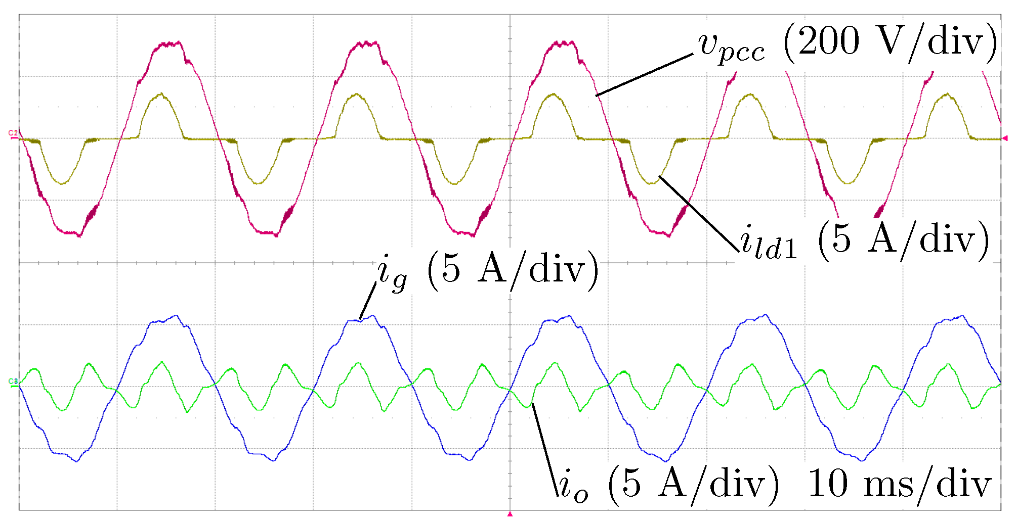
Figure 13.
Measured fundamental current amplitude (through FFT) as a function of its reference .
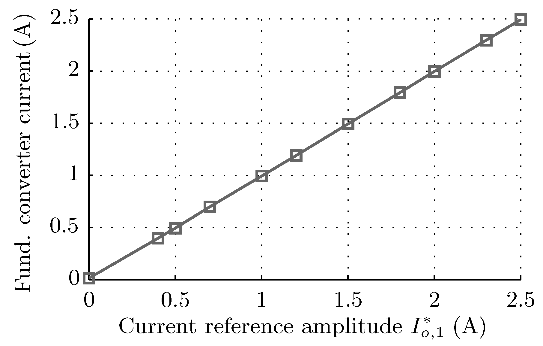
Figure 14.
Experimental results of the impact of the grid frequency estimation error on the add-on harmonic attenuation.
Figure 14.
Experimental results of the impact of the grid frequency estimation error on the add-on harmonic attenuation.
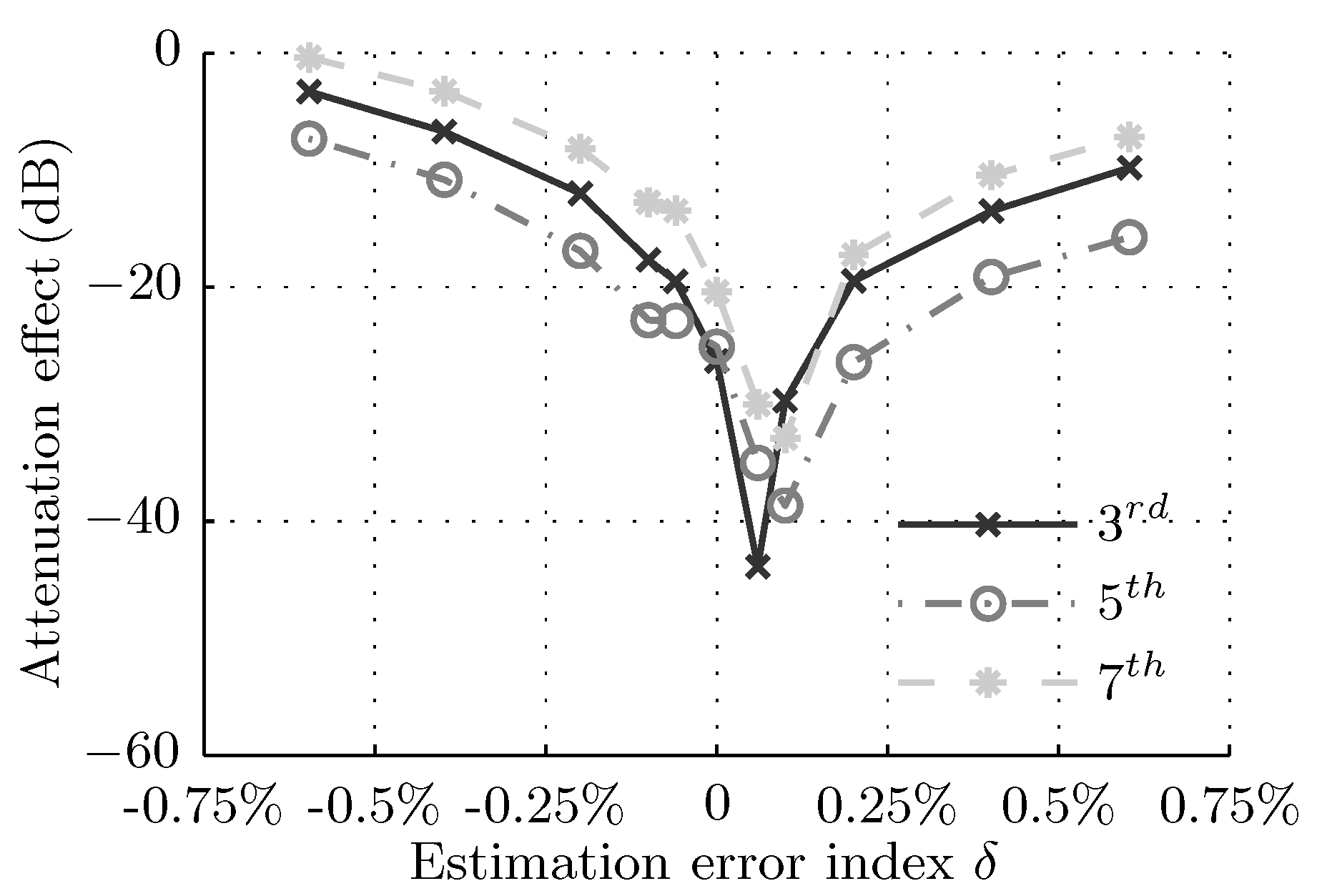
Figure 15.
Experimental results. The local voltage 3rd harmonic attenuation as a function of the resonance filter gain , , and .
Figure 15.
Experimental results. The local voltage 3rd harmonic attenuation as a function of the resonance filter gain , , and .


Table 1.
Nominal parameters for the experimental setup, referring to the diagram shown in Figure 1.
Table 1.
Nominal parameters for the experimental setup, referring to the diagram shown in Figure 1.
| Description | Symbol | Value |
|---|---|---|
| DC power supply voltage | ||
| Converter switching frequency | ||
| LCL filter | ||
| 0.2 | ||
| 0.2 | ||
| Linear load resistance | 94 | |
| Non-linear load Crest factor | 2 | |
| Non-linear load power factor | ||
| Non-linear load rms current | ||
| Grid rms voltage | ||
| Nominal grid frequency | ||
| Grid impedance | ||
| 0.4 |
Table 2.
Default parameters of the control strategy.
| Description | Symbol | Value |
|---|---|---|
| (Estimated) grid frequency | ||
| Sampling frequency | ||
| Proportional resonance filter | 30 | |
| 6000 | ||
| Resonance filters | 120 | |
| Selective harmonic order | ||
| Amplitude of the desired fundamental output current |
© 2018 by the authors. Licensee MDPI, Basel, Switzerland. This article is an open access article distributed under the terms and conditions of the Creative Commons Attribution (CC BY) license (http://creativecommons.org/licenses/by/4.0/).
Share and Cite
MDPI and ACS Style
Zhang, Y.; Roes, M.G.L.; Hendrix, M.A.M.; Duarte, J.L. Voltage Harmonic Suppression by Means of Grid-Connected Converters Using only Local Measurements. Energies 2018, 11, 2515. https://doi.org/10.3390/en11102515
AMA Style
Zhang Y, Roes MGL, Hendrix MAM, Duarte JL. Voltage Harmonic Suppression by Means of Grid-Connected Converters Using only Local Measurements. Energies. 2018; 11(10):2515. https://doi.org/10.3390/en11102515
Chicago/Turabian StyleZhang, Ya, Maurice G. L. Roes, Marcel A. M. Hendrix, and Jorge L. Duarte. 2018. "Voltage Harmonic Suppression by Means of Grid-Connected Converters Using only Local Measurements" Energies 11, no. 10: 2515. https://doi.org/10.3390/en11102515
Note that from the first issue of 2016, this journal uses article numbers instead of page numbers. See further details here.