Novel Receiver-Enhanced Solar Vapor Generation: Review and Perspectives


Department of Mechanical and Materials Engineering, Masdar Institute, Khalifa University of Science and Technology, P.O. Box 54224, Abu Dhabi, UAE
*
Author to whom correspondence should be addressed.
Energies 2018, 11(1), 253; https://doi.org/10.3390/en11010253
Submission received: 30 November 2017
/
Revised: 5 January 2018
/
Accepted: 16 January 2018
/
Published: 20 January 2018
(This article belongs to the Special Issue The Future of Solar Thermal Energy)
Abstract
:Efficient solar vapor/steam generation is important for various applications ranging from power generation, cooling, desalination systems to compact and portable devices like drinking water purification and sterilization units. However, conventional solar steam generation techniques usually rely on costly and cumbersome optical concentration systems and have relatively low efficiency due to bulk heating of the entire liquid volume. Recently, by incorporating novel light harvesting receivers, a new class of solar steam generation systems has emerged with high vapor generation efficiency. They are categorized in two research streams: volumetric and floating solar receivers. In this paper, we review the basic principles of these solar receivers, the mechanism involving from light absorption to the vapor generation, and the associated challenges. We also highlight the two routes to produce high temperature steam using optical and thermal concentration. Finally, we propose a scalable approach to efficiently harvest solar energy using a semi-spectrally selective absorber with near-perfect visible light absorption and low thermal emittance. Our proposed approach represents a new development in thermally concentrated solar distillation systems, which is also cost-effective and easy to fabricate for rapid industrial deployment.
1. Introduction
Solar thermal energy is considered to be the most abundant source among all the available renewable energy sources [1,2]. The energy emitted by the Sun which is intercepted by the Earth is about 1.8 × 10¹⁴ kW. 60% of the total energy reaches the Earth’s surface, while the rest is reflected back into space. Just 0.1% of this energy can generate 3000 GW of electricity, four times higher than the world’s current total generating capacity. Most interestingly, the annual solar energy of 3,400,000 EJ striking the surface of the Earth is an order of magnitude greater than all the estimated non-renewable energy resources combined, including nuclear and fossil fuels [3]. Although fossil fuels are still the dominant energy resources, conflicts have been induced by global supply and demand fluctuations of oil or gas [4,5]. Moreover, combustion of fossil fuels causes pollution and global warming by emitting oxides of carbon and nitrogen and aerosols [5].
Meanwhile, with the continuous increase in the human population, the worldwide accessibility to fresh water is becoming a severe concern. According to the WHO/UNICEF Joint Monitoring Program report, 2.1 billion people worldwide lack access to safe and readily available water at home [6]. Fortunately, recent research activities in producing fresh water give hope in reducing the water shortage around the globe. Conventionally, various methods such as desalination and filtration are trying to alleviate the fresh water stress [7,8]. However, these methods have high operational costs, requiring large capital resources and infrastructure. Besides, the intensive use of chemicals such as ammonia, alkali bases, chlorine-based compounds, and some inorganic salts also cause contamination and salting of existing water resources [9,10].
Vaporization of water is a common phenomenon that contributes significantly to the utilization and production of fresh water in living organisms and industry [11,12]. In industries, the steam is generated by two means. The first one is heating the bulk water by combustion of coals, natural gases or biomass [13,14]. Natural gas is heavily used in Western countries and the Middle East for integrated water and power production [15], which causes the environmental pollution. The second is solar-driven steam generation, in which water is heated to produce vapor by concentrating sunlight using optical lenses, resulting in high cost with low efficiency [16]. Recently, scientists and engineers have been actively developing cost-effective solar-driven steam generation systems.
The deployment of solar energy has made remarkable progress owing to the continuous research and cost reduction of solar energy technologies [17,18]. Typical solar thermal technologies include solar power plants, solar chimneys, solar water heaters, solar cookers, solar driers, solar desalination, solar ponds, and solar stills (Figure 1). Reference [5] briefly presented performance analyses of existing designs, numerical simulations, and the fabrication methods of various solar thermal technologies. Conventionally, fresh water production using solar technology includes evaporative methods based on desalination, solar ponds, and solar stills [19,20,21]. These technologies utilize costly optical concentration systems to heat the bulk water, which needs engineering expertise and expensive infrastructure. In some cases, the materials with high light absorption capability are utilized, but the solar energy conversion efficiency is still relatively low (e.g., 30–40%), because of heat dissipation to the bulk water. The overview of design and performance of solar stills and solar desalination technology has been reviewed previously [19,20,21,22].
Recently, researchers are trying to achieve more efficient, self-powered, and portable solar energy harvesting systems for vapor/steam generation. The emerging solar steam generation systems rely on novel solar receivers to efficiently vaporize water. In this regard, there are two main streams in ongoing research: volumetric solar receivers and floating solar receivers. In this review, we focus on the recent developments of novel solar receivers for steam generation, from the light absorption to the vapor generation. In the first section, we highlight the plasmonic effects of colloidal hollow nanoparticles in volumetric solar receivers with the help of their extended active surface. We have summarized the recent research progress and challenges in using these solar receivers for vapor generation. In the second section, we highlight the recent development of floating solar receivers, which are becoming popular owing to their low cost and design simplicity. This section includes some insight into the mechanisms involved: light absorption (plasmonics, broadband absorption, and spectral selectivity), thermal management (minimizing conduction, convection, and radiation heat losses), liquid propagation, thin film evaporation, antifouling, and condensation. Then we review a variety of materials used in floating solar receivers to achieve higher solar to thermal conversion efficiency. We also highlight the two routes to produce high-temperature steam by using optical and thermal concentration. Lastly, we have concluded the review by proposing our own scalable devices to generate steam under one sun irradiance.
2. Volumetric Solar Receivers for Vapor Generation
In the past decade, progress in the field of nanotechnology has brought a revolution in the design of smart materials for various applications [31]. Nanoparticles, clusters of closely packed atoms (10–100 nm), are the basic units of this research. These materials are of high interest in optics, as they contain a large density of polarizable units in a small volume. These highly polarizable nanoparticles interact strongly with electromagnetic radiation. In the case of noble metallic nanoparticles, the high density of free electrons causing the related optical resonances are called the electron plasma, while the corresponding optical excitations are called plasmons [32,33]. Plasmonics have quite extensive applications in the area of solar energy conversion as the localized plasmon resonance at the surface of metallic nanoparticles leads to enormous enhancements of near field intensity and consequent heat localization around the nanoparticles [34].
The mechanisms of nanoparticle-enhanced vapor generation can be summarized in the following points (Figure 2):
- Incident light absorption to produce heat by plasmonic nanoparticles, and rapid transfer of heat to the water in the immediate vicinity.
- Heating of thin water layers around the plasmonic nanoparticles to its boiling point to produce steam.
- Owing to the poor thermal conductivity of steam, inhibition of heat transfer from the heated nanoparticle to the bulk water.
- Gradual growth of thickness of the steam shell to several hundred nanometers upon further heating of nanoparticle by sunlight. Decrease in weight of the steam/nanoparticle assembly as compared with equivalent volume of water to creates buoyancy force.
- Lastly, the steam bubble reaches the surface and steam escapes from the water.
The key mechanism involved in volumetric solar receivers for vapor generation is plasmon enhanced light absorption. Localized surface plasmon resonance is an optical phenomenon, where the collective oscillations of free conduction electrons in metallic nanoparticles are excited by the light with the wavelength comparable with or larger than the particle size [35]. As in the resonance band, metallic nanoparticles, such as gold, silver, and platinum, are highly efficient in absorbing and scattering [36]. The plasmon resonance wavelength can be tuned by the composition, size, geometry, inter-particle gap width, and surrounding environment [37]. By using the Finite-Difference Time-Domain (FDTD) method, the authors have shown that the plasmon resonance wavelength of gold-shell silica-core nanoparticles can be tuned from visible to near-infrared regions by changing the particle size and the inter-particle distance (Figure 3a–c). With the excitation of plasmonic resonances among metallic nanoparticles, strong local field enhancement on the metallic surfaces or at the gap among neighboring nanoparticles is achieved, assisting heat localization around the nanoparticles to heat the surrounding media, as shown in Figure 3c.
Halas et al. introduced the term of “heat localization” and investigated the light absorption and scattering by randomly dispersed particles in a solution, as shown in Figure 3d. This light-matter interaction results in highly localized heating, which can be described by the classical heat transfer approach [39]. In the case where the average distance among the particles is shorter than the wavelength of light this causes multiple scattering, which leads to the weak localization of light [38]. When the concentration of nanoparticles is comparatively low, the light-matter interaction is determined by individual particles and their optical properties. Figure 3e presents experimental images tracing the path of light in a nanoparticle solution. For higher concentrations, the back scattering of light from the fluid surface is very strong, thus, inhibiting any deep light penetration to the solution. This observation of scattered light closely resembles to those predicted by the multiple-scattering simulations (Figure 3e), which incorporate the dipole scattering distribution of the resonant particles. In the following section, we review and classify the recent development in solar steam generation using volumetric receivers into three major categories, starting from laser irradiance of metallic nanoparticles, to the solar irradiance of core-shell plasmonic nanoparticles and then to the carbon-based nanofluids for steam/vapor generation.
2.1. Nanobubbles Formation Using Conductive Nanoparticle under Laser Irradiance
Laser irradiance on nanoparticles has been shown to induce dramatic localized heating and even vaporization of their hosting medium [40,41]. Lukianova-Hleb et al. were the first group to present the idea of introducing short laser pulses to generate transient vapor nanobubbles around plasmonic nanoparticles [42]. Figure 4a presents the generation and detection of plasmonic nanobubbles around gold nanoparticles using 633 nm laser irradiance. Later, the nanoparticle is exposed to a short pump laser pulse (0.5 ns, 532 nm) that produces a vapor layer around the heated nanoparticle (Figure 4b). In the second stage, when the pressure inside the vapor layer exceeds the outer pressure to a certain extent, the vapor begins to expand into a bubble. Finally, the bubble collapses at the end of its lifespan (10–1000 ns).
2.2. Vapor Generation Using Core Shell Nanoparticles under Solar Irradiance
The Halas group introduced a new degree of freedom to the design of metal nanoparticles: core shell plasmonic nanoparticles [38]. They claim these nanoparticles with dielectric core and noble metal shell produce steam when immersed in water under direct sunlight irradiance. In this process, individual nanoparticles efficiently absorb light to heat up, and then transfer energy to the surrounding fluid. Instead of gradually heating bulk water, Halas et al., found that steam is generated from the solution right when the light irradiance starts [32,39]. To quantify the nanoparticle based steam generation process using sunlight, two solutions of absorbing nanoparticles, (i) SiO2/Au nanoshells and (ii) water-soluble N115 carbon nanoparticles, as shown in Figure 4c,d. Upon solar irradiance, the pressure over the solution of SiO2/Au nanoshells began to increase within the 5 s, indicating vapor generation. For carbon nanoparticles the pressure increase was delayed by just over 20 s. A thermodynamic analysis showed that 80% of the absorbed sunlight is converted into thermal energy for water evaporation and only 20% of the absorbed light energy is converted into heating of the surrounding liquid [39]. Jin et al., used gold nanoparticles-based solar volumetric receivers. With the help of three dimensional numerical models, they simulated the temperature profile within the sample fluid and the heat transfer between a single particle and the surrounding fluid. Their results indicate that 12.75 ppm gold nanoparticles dispersion can achieve a very high solar thermal conversion efficiency of 80.3% using optical concentration of 220 Suns [44]. Amjad et al., also used gold nanofluids under solar irradiance of 280 suns to generate steam. They found highly non-uniform temperature distribution, and identified three phases of heating, (i) surface heating, (ii) sub-cooled boiling, and (iii) saturated boiling. They reported 95% of solar thermal efficiency using 0.04 wt % gold nanoparticle solution [45]. Mahfuz et al., [46] also achieved vapor generation efficiency of 63.82% at solar concentrations of 10 suns using 0.5 wt % of plasmonic nanofluid of silica-core decorated with Ag nanoparticles.
By utilizing a nanomasking approach [47] combined with a silver galvanic reaction [48], Zielinski et al., introduced the concept of hollow plasmonic nanoshells of an alloy of Ag/Au [49]. The hierarchical mesoporous structures extend the thermal cavity aspect ratio by improving the diffusion transport through the shell barrier. Results demonstrated that solar vapor generation process is governed by shell thickness and uniformity and the surface ligands. The chemical nature of the ligands helps to modify the thermal resistance of particle surface The non-uniformity and pores of shell enable the vapor bubbles to escape while also strongly contributing to an enhanced optical absorption [50].
2.3. Vapor Generation Using Carbon Nanofluids under Solar Irradiance
Besides metal nanoparticles, more environmentally friendly and cost-effective carbon materials are being widely used as solar thermal absorbers. Particularly, graphite/graphene, and carbon nanotube materials comprising sp2-hybridized carbon atoms are excellent optical absorbers due to the π-band’s optical transitions [51,52]. Ni et al., reported vapor generation efficiencies of 69% at 10 suns using carbon black, graphitized carbon, and graphene suspended in water [43]. The nanofluid heating and vapor generation occur due to classical global heating of the suspension fluid. Nanofluids with well-dispersed particles generated heat closer to the liquid-vapor interface, and had a higher interfacial temperature and overall evaporation rate. The varied nanofluid dispersions are due to the different zeta potentials of the nanoparticles in the water solution. Nanofluids with high magnitude of zeta potential are electrostatically stable, while nanofluids with low magnitude zeta potentials tend to agglomerate [53]. Carbon black-based nanofluids have been reported to have a zeta potential of only ≈−10 mV, [54,55] resulting in less stability and agglomeration, while the graphene and graphitized carbon black nanofluids reportedly have zeta potentials around ≈ −40 mV [38], resulting in better stability, less agglomeration, and enhanced transient performance. Despite the fact graphitized carbon black nanofluid reach the steady-state faster (Figure 4e), the graphene nanofluid reaches a similar transient efficiency (69 ± 4% for 0 << 6000 s). The transient efficiencies of graphitized carbon black and graphene nanofluids are 7% higher than that of carbon black nanofluid. During the shorter measurement period, this transient efficiency discrepancy increases as shown in Figure 4f.
Wang et al., utilized iron oxide magnetic nanoparticles, which were decorated with reduced graphene oxide, for solar assisted desalination [56]. Eventually, those nanoparticles can be recollected by applying an external magnetic field. The evaporation efficiency of saline water (3.5 wt %) reached up to 60% under solar irradiance of 1 kW m−2. They also examined the evaporated water from CdCl2 solution using inductively coupled plasma atomic emission spectroscopy, which demonstrates the ability of this system to treat cadmium pollution, indicating the practical nature of this system and the existence of many potential applications besides desalination and wastewater treatment projects. Mei et al., reported slight improvement in steam generation efficiency by incorporating the gold nanoparticles to the graphene sheets. With gold nanoparticles, the steam generation efficiency improved from 48.4% to 59.2% under the solar irradiance of 0.7 kW m−2 [57]. Benefiting from the nano size and narrow-bandgap features, the Ti2O3 nanoparticles possessing strong light absorption have also shown potential use in seawater desalination and purification [58].
2.4. Challenges of Volumetric Solar Receiver
As discussed earlier, under high solar irradiance, the temperature of noble metal particles [42], semiconductor nanoparticles [39], or carbon-based nanoparticles [43] can reach well above the boiling point of water, and the solar thermal energy is suitable to evaporate the surrounding water, which results in solar steam generation. However, volumetric solar receivers have faced some challenges. For example, gold nanoparticles with collective plasmonic properties are widely used as an absorption layer, but they may fuse together after extended irradiance, which weakens the electronic oscillations at the particles’ surface [59]. Also the absorptivity of plasmonic nanoparticles is limited in the short wavelength range of the solar spectrum. Another key factor to quantify the solar thermal efficiency is the concentration of nanofluids. With low concentrations of nanofluids, the solar thermal conversion efficiency will increase even with low power density of incident light. When the concentration of nanofluids is higher than the critical value, the light will be confined only in the upper layer. Additionally, the large concentration of the nanomaterials would cause the wastage of raw materials and increase the cost.
Additionally, all those methods of generating steam in volumetric nanofluid receivers rely on surfaces or cavities that absorb solar radiation, and this requires high light intensities (usually above 10 suns), which also increases the surface heat loss. Nevertheless, it is worth noting that the higher optical concentration does not always lead to the higher solar thermal efficiency of the system. It is reported by Halas’ group that the optical concentration of 100 suns (100 kW m−2) was used to produce the steam in the ice water mixture in just 10 s. However, the total solar thermal conversion efficiency was only 24%. Therefore, these challenges limit the use of volumetric solar receivers in stand-alone solar steam generation systems.
3. Floating Solar Receivers for Vapor Generation
In order to reduce heat loss, more studies have been devoted to localize heat and to use thermally insulated structures. These structures should have three main characteristics in common. The first one effectively absorbs the sunlight to generate heat. The second one is a low thermal conductivity material to prevent heat from transferring away from the absorber surface. The third one is a hydrophilic wicking surface to promote fluid flow to the surface. The efficiencies of solar thermal conversion from 57% to 85% are obtained by those structures in a certain intensity of solar irradiance. The individual role of each mechanism in affecting the overall performance of the vapor/steam generation process is discussed as follows.
3.1. Mechanismof Solar Thermal Energy Transport
3.1.1. Light Absorption
The study of solar absorber coatings with efficient light absorption properties over a broad range of wavelengths, is essential and critical to many solar thermal applications including solar steam generation [60,61,62,63]. An ideal absorber coating surface eliminates the transmittance and reflectance while exhibiting maximum absorption over a broad spectral range. There are three mechanisms involved in general: (i) efficient antireflection achieved by multilayer impedance matching [64], (ii) photonic crystals with high density of optical modes [65], and (iii) strong light coupling with nanostructures for efficient light absorption [66]. In current applications, absorbers are usually fabricated as: multilayers, metal-dielectric composites, surface texturing, and blackbody [67,68,69]. Spectrally selective absorptance is mainly achieved by the first two types of coatings with metallic substrates. Blackbody and surface texturing absorbers are made of single material that intrinsically absorbs light in the wider range. Blackbody absorbers are usually used in low temperature applications owing to their high absorptance and low cost. Surface texturing is a way to modify the absorptive material surfaces into light trapping porous structures [70].
The light absorption performance of solar absorbers is boosted in the visible and near-infrared regions by introducing metallic nanostructures, such as patterning nanoholes, nanoparticles, and nanodisks on the absorber surface, as shown in Figure 5a–c [71]. However, these absorber coatings are fabricated mainly by top-down lithographic approaches such as e-beam lithography, laser interference lithography, with inherent limitations on fabrication throughput, spatial resolution, and scalability. Recent studies on plasmonic absorber based on lithography-free fabrications have attracted much attention owing to their cost-effectiveness and scalability (Figure 5d). Lu et al., fabricated scalable ultrathin nanocomposite films with self-formed topping plasmonic nanoparticles to achieve near perfect light absorption in the wavelength ranges from visible to near-infrared regions. The simulation results show that Ag topping nanoparticles enhance the light absorption of the nanocomposite absorber in the visible range as in Figure 5e,f [72].
3.1.2. Thermal Management
In solar thermal conversion systems, the absorbed solar energy is converted into heat at the absorber surface, and then transfers it to the thermal system. The absorbed solar energy, thermal emission, and convection heat transfer determine the temperature of the absorber in the equilibrium state, as described by the Equation (1):
where, is the solar absorptance, is the thermal emittance, is the Stefan-Boltzmann constant, Th is the absorber temperature, Tamb is the temperature of the environment, hconv is the convective heat transfer coefficient , and Qsun is the total solar irradiance. The solar absorptance is defined as:
where, S(λ) is the wavelength-dependent solar irradiance, A(λ) is the spectral absorptance. The numerator of this equation is the total absorbed solar energy; the denominator is the incident solar irradiance Qsun. According to the Kirchhoff’s law of thermal radiation, the thermal emittance, εt is defined as follows:
where, B(λ) is the spectral distribution of blackbody radiation. Although Equations (2) and (3) look similar, the wavelength ranges are different. The range of solar absorptance is between the visible and near-infrared regions of solar irradiance, but that of the thermal emittance is temperature-dependent and usually in the infrared regions, where the blackbody radiation dominates [73,74].
By following the Equation (1), a solar absorber can achieve high temperature by maximizing the solar absorptance while keeping low thermal radiation and low heat convection. Typical spectrally selective solar absorbers, such as cermet absorbers and lithography-free ultrathin multilayer absorbers, are designed to have a perfect cutoff wavelength, as shown in Figure 6a, which avoids the absorption band in the blackbody radiation distribution [72]. However, it is more realistic to consider the absorption tailored near zero in the longer wavelength ranges [75]. For solar thermal energy applications, optical concentrator is used to increase the solar irradiance for achieving high temperature. Authors described that if considering a solar absorber with thermal emittance of 0.1 in the near-vacuum environment (hconv = 0.1 W m−2 K−1), the relation between the surface temperature and solar absorptance for different optical concentrations is shown in Figure 6b. At higher optical concentrations (100×), a good absorber with solar absorptance of 0.9 can easily achieve high surface temperature of 1600 °C. However, at higher optical concentrations, it is still challenging for the absorber surface to maintain low thermal emittance and thermal stability [76,77].
Thermal management is very important to avoid any type of heat losses while maintaining thermal concentration, which is the ratio of sunlight absorption area to the evaporation area, to achieve better vapor generation efficiency [73]. For low temperature applications, such as solar desalination and solar hot water heater, the required temperature is less than or equal to 100 °C. Chemically fabricated solar absorbers are usually favored by the solar desalination industries owing to their fast, cheap, and large scale fabrication. When considering one-sun solar irradiance and taking the heat convection conditions into account, we find that the absorber temperature directly exposed to ambient environment can hardly reach to 100 °C. By isolating the absorber to reduce the convection heat loss, another key factor, thermal radiation, starts to dominate the temperature drop in the equilibrium state. Through theoretical calculations, the authors explained that by assuming the low convection heat loss (hconv = 10 W m−2 K−1), under one-sun solar irradiance, the absorber can achieve 100 °C by having the solar absorptance larger than 0.8 and thermal emittance less than 0.4, as shown in Figure 6c,d. Similarly, Figure 6e presents the dependence of water mass change and thermal concentration under different thermal emittance by maintaining the solar absorptance to 90%. As the radiation heat loss/thermal emissivity increases, the rate of mass change also decreases considerably, thus, reduces the steam generation efficiency.
3.1.3. Liquid Propagation
It is very important to have a continuous water supply to the absorber surface for efficient steam generation. Evaporation from planar surfaces is typically due to the temperature difference between the surface and the ambient, as well as the difference between the saturation vapor pressure and the internal liquid pressure [78]. The use of porous media and heat localization at the absorber surface may provide an alternative path. Such a scheme involves coupling the absorbed heat with capillary fluid flow in porous media, where the “wicking” of the liquid in the channels provides a driving force for the liquid flow and subsequent evaporation. A promising strategy to enhance evaporation rate is utilizing the thin-film evaporation [11]. When liquid wets a solid wall, the extended meniscuses are typically divided into three regions: (i) adsorbed region, (ii) thin-film region, and (iii) intrinsic meniscus region. The strongest evaporation happens when the water film is thin enough (1 μm or less) so that the thermal resistance across the film becomes smaller than the interfacial resistance to evaporation [79]. Therefore, the heat loss to the surrounding water is very low and the energy efficiency increases. Micro or nanoscale surface modifications of the wick can enlarge the thin film region for higher energy efficiency (Figure 7a). Besides, the efficiency can also be increased by improving the wettability of the solid wall [80].
Recently, Canbazoglu et al. [81] presented enhanced solar evaporation of water in porous media, through capillary mediated forces and surface treatment. Generally, in solar evaporation involving porous media, there are several variables that govern the efficiency via the throughput and conversion of the liquid water to water vapor. These include the surface chemistry of the materials in the porous medium, pore size and the distribution, and the relative contribution of conductive and convective heat transfer. The influence of wick hydrophilicity on the net water evaporation flux across the interface is shown in Figure 7b. For the liquid on the wall, its evaporation predominantly occurs in an intermediate evaporating thin film region between the intrinsic meniscus (i.e., corresponding to the bulk) and a non-evaporating film region, as shown in Figure 7c.
3.1.4. Antifouling and Durability
At the core of processes such as water distillation using contaminated and sea water, organic fouling is always a problem. In solar steam generation experiments, the absorber surface exposed to the ambient and the hydrophilic wick in contact with water easily got fouling. Thus the integrated design of absorbers and the wick with anti-fouling performance is critical to improve the efficiency and the life span steam generating device. Since the discovery of water splitting by Fujishima and Honda in 1972 [82], the photocatalytic properties of TiO2 have presented an important solution to the fouling and to the removal of organic contaminants in polluted waters. A photocatalytic reaction is initiated when a photoexcited electron is promoted from the filled valence band to theconduction band of semiconductor, which creates the electron hole pair (Figure 8a) [83]. The positive holes and negative electrons help to degrade the organic pollutants using redox reactions [84,85,86]. Besides TiO2, other materials, such as Si, ZnO, WO3, CdS, ZnS, SrTiO3, SnO2, WSe2, Fe2O3 [84,87,88] are also used for photocatalysis.
Stoichiometric anatase TiO2 is active upon UV light irradiation, which is only 3–5% of the solar spectrum. Thus, in order to enhance the efficiency of TiO2 under solar irradiance, attempts were made to extend the absorption range of titanium dioxide into the visible-light region (Figure 8b) [89]. Some methods used to improve the efficiency of TiO2 are to incorporate impurities by doping [91], sensitization [92], surface modification [87], and composites [85]. Liu et al. [90] reported a scalable method to enhance the visible light absorption by depositing TiO2 on copper substrate. The TiO2/Cu stacked structure shows a strong absorption band in the visible range due to the absorption of metallic Cu substrate, as shown in Figure 8c. The decrease in spectral absorptance of methylene blue confirms the photocatalytic and antifouling properties of TiO2 nanostructures deposited on Cu under solar irradiance (Figure 8d). Therefore, these smart materials can provide the solution for enhanced light absorption in the visible range with solar-assisted anti-fouling properties.
3.1.5. Condensation and Collection
In conventional solar stills, the evaporated water vapors condense on the transparent cover to form a thin liquid layer and then water condensate is collected. In this case, the transparency of condensate-adhered cover affects the availability of sunlight to the absorber top surface, consequently the rate of evaporation and condensation of water vapors. There is research gap when it comes to the collection of produced water vapors in recently developed solar steam generation devices. However, the filmwise and dropwise condensation on flat and nano-/micro-structured surfaces is a well-studied phenomenon, and we can take advantage from the development of nanotechnology to design an appropriate surface, which can effectively enhance the condensation process without altering the transmittance of the cover [93]. Our previous studies have shown the role of surface wettability to achieve enhanced dropwise condensation, where droplet growth and efficient condensate removal are two key contributing factors (Figure 9a). Aili et al. [94] studied the nucleation of droplets, as it is the first stage of phase change phenomena, including condensation on nanostructured superhydrophobic surfaces. They showed how the surface nanostructure density affects the nucleation density of water droplets because of the decreased energy barrier of nucleation in cavities within the nanostructures, as shown in Figure 9a–c. Another important factor to influence the rate of condensation is the surface wettability. Li et al. [95] reported the change in jumping velocity by altering the surface wettability for different droplet sizes, as shown in Figure 9d.
3.2. Recent Development in Floating Solar Receivers for Vapor Generation
3.2.1. Carbon/Graphene Based Floating Solar Receiver
In order to realize the idea of floating solar receivers for vapor generation, Ghasemi et al., proposed a novel approach of double layered structure (DLS). It localizes the sunlight for evaporation and minimizes the heat losses, leading to enhanced solar thermal efficiency at low optical concentration [96]. The DLS consists of graphite particles supported on carbon foam, and upon solar irradiation of 10 kW m−2, it yields a solar thermal conversion efficiency of 85% (Figure 10a–c). In this design, heat localization is achieved by: (i) utilizing the broad band light absorption properties of graphite particles (Figure 10b), and (ii) thermally insulating properties of the carbon foam. Thus, fluid wicks to the absorber hot spot by the hydrophilic and porous nature of the insulating foam. However, by decreasing the flow rate in the carbon foam, localizing heat and optimizing the porosity, and thickness of each layer, better solar thermal efficiency can be achieved even at lower optical concentrations. This work provides a new approach to solar-assisted steam generation for many potential applications.
In order to further boost the solar thermal conversion efficiency, it will be ideal to have one material possessing all the required thermal, optical, and wetting properties to avoid the interference from the composite interfaces [97]. To cope with this challenge, graphene-related materials was considered as one of the promising candidates owing to their low molar specific heat, high Debye temperature, broadband light absorption, and tunable thermal conductivity by chemical doping [98]. However, the 2D flat feature and hydrophobic nature prevents graphene as the sole component for steam generation [99]. Ito et al., altered the wetting properties of graphene foam, by nitrogen doping for steam generation. Figure 10 d–f present a single piece of ~35 μm thick N-doped graphene foam with monolithic open pore, which effectively realizes the energy conversion from sunlight to high-temperature steam by heat localization with an efficiency of 80% [98]. Later on, Yang et al. [100] functionalized graphene using hydrophilic groups, such as hydroxyl (−OH) and carboxyl (−COOH) groups. With small increases in hydrophilic functional groups, the overall solar-to-vapor efficiency is improved from 38% to 48% under 1 sun irradiance. The surface functionalization of graphene became popular to improve the hydrophilicity of 3D structures for steam generation experiments [101]. Guo et al. [102] achieved 89.2% under one sun with 60 mg of reduced graphene oxide.
Fu et al., fabricated graphene aerogels from graphene oxides to harvest solar energy. Being blackbody absorber, graphene aerogel not only converts almost the entire incident solar light to thermal energy but also floats on water while supplying the interface water through capillary force for constant steam production. Solar steam generation efficiencies of 53.6 ± 2.5% and 82.7 ± 2.5% have been achieved at light intensities of 1 and 10 kW m−2, respectively [103]. The key factor to achieve higher efficiency is the design of carbon material structure. A vertically aligned carbon nanotubes array, where the carbon nanotubes are aligned to form a 3D forest-like structure, is well-known as the blackest material in the world. It has been reported that vertically aligned carbon nanotubes arrays possess a nearly constant optical absorption of 98–99% across a wide spectral range from 200 nm to 200 μm and thus behave most similarly to a blackbody, promising its great potential for solar energy harvesting [104]. In addition, the frictionless surface of carbon nanotube walls may lead to an ultrahigh fluid velocity of water outside the carbon nanotubes, which can further enhance the evaporation of water. The calculated thermal conversion efficiency using vertically aligned carbon nanotubes were as high as 90% using optical concentration of 30% (Copt = 1), 60% (Copt = 5), 78% (Copt = 10), and 90% (Copt = 15), respectively [104].
Recently, Li et al., utilized the fastest growing technology of additive manufacturing (3D printing) to construct an all-in-one evaporator with a concave structure for solar steam generation [105]. The integrated structure consists of the carbon nanotubes/graphene oxide as broadband solar absorber and graphene oxide/nano-fibrillated cellulose porous layer for liquid propagation, as shown in Figure 11a. The solar-steam-generation device has a high porosity (97.3%) and broadband solar absorption (>97%). With low thermal conductivity of 0.06 W m−1 K−1, they have reported the solar steam efficiency of 85.6% under solar irradiance of 1 kW m−2, as shown in Figure 11b,c.
3.2.2. Organic-Inorganic Nanocomposite Based Floating Solar Receivers
Another approach to produce low-cost materials for solar steam generation is the synthesis of organic-inorganic nanocomposites. Polyurethane foam is a highly attractive material with diverse industrial application owing to its micro porosity, excellent thermal insulation properties, and facile and scalable synthesis [106]. Wang et al., synthesized reduced graphene oxide-polyurethane nanocomposite foam through the reaction of diisocyanates, polyether, and polyethylene glycol directly inside the dimethylformamide dispersion of graphene oxide, followed by the high temperature foaming and chemical reduction (Figure 12a–c). The hydroxyl and carboxyl groups of modified graphene oxide sheets react with the isocyanate groups to form stable chemical bonds, which help in fabrication of stable organic-inorganic nanocomposite foam. This type of nanocomposite foam has exhibited a solar thermal energy conversion efficiency of 64 and 81% at solar irradiance of 1 and 10 kW m−2, respectively [106]. Later on, they also used graphene oxide-cellulose ester membranes by introducing polyethylenimine as a crosslinking agent, (Figure 12d,e). The double-layer of graphene oxide-cellulose ester system showed high steam evaporation efficiency up to 52% under 1 kW m−2 of solar irradiance [107].
3.2.3. Bio-Composites Based Floating Solar Receivers
Tian et al., proposed that 3D open porous structures with high surface area can serve as an ideal platform to achieve optically active 3D materials [108]. They fabricated optically active foams by incorporating plasmonic nanostructures into the bacterial nanocellulose aerogels. Owing to their versatility, Tian et al., applied plasmonic biofoams for a variety of applications including (i) ultrasensitive chemical detection; (ii) steam generation through plasmonic solar thermal heating; and (iii) optical control of enzymatic activity by triggered release of molecules encapsulated within the functional foam [109]. The plasmonic paper and biofoam exhibited significant temperature rise of 23 and 15 °C, respectively, within the first 300 s of irradiance followed by stabilization during subsequent irradiance.
Without considering losses involved in the test facility, such as reflection, surface radiation, and test chamber losses, the evaporation efficiency of plasmonic aerogel was calculated to be 76.3% at concentrated solar irradiation of 51 kW m−2. Bacterial nanocellulose incorporated with flakes of graphene oxide has also shown a steam generation efficiency of 83% at concentrated solar irradiation of 10 kW m−2 [109]. In addition, the natural 3D structures of plants maximize light absorption from a wide range of incident angles throughout the day. Another approach was recently proposed to use the natural plants based floating materials with absorber coating on top surface. Natural and carbonized mushrooms achieved around 62% and 78% conversion efficiencies under 1 kW m−2 solar irradiance, respectively (Figure 13a–d). It is found that this capability of high solar steam generation is attributed to the unique natural structure of mushroom, umbrella-shaped black pileus, porous context, and fibrous stipe with a small cross section [110]. Inspired by the water transpiration behavior in trees through xylem from roots to the leaves surface, carbon nanotube coated balsa wood [111], flame coated wood [112], and graphene oxide coated wood [113], demonstrated an efficiency of 81, 72, and 83% at solar irradiance of 10, 1, and 12 kW m−2, respectively. Thermal conductivities of and solar thermal conversion efficiency of various materials under 1 sun solar irradiance are tabulated in Table 1.
3.3. Solar Assisted Water Desalination Using Floating Solar Receivers
Efficient utilization of solar energy to generate the clean water from seawater and even industrial wastewater has great potential to solve the shortage of fresh water resources [115,116]. Solar desalination has become one research hotspot of solar steam generation from seawater. Zhou et al., introduced plasmon-enhanced solar desalination device. They fabricated it by using self-assembly of aluminum nanoparticles into a 3D anodized aluminum oxide porous membrane [117]. They used a combination of anodization, self-assembly, and physical vapor deposition method to get nanoporous membranes (Figure 14a–c). It is obvious that the original transparent anodized aluminum membranes turned black in color after the deposition of the aluminum nanoparticles, which is a direct indication of the efficient and broadband light absorption in the visible and near infra-red range (400–2500 nm). Zhou et al., also deposited plasmonic nanoparticles on nanoporous membrane template. They claim achieving over 90% efficiency under solar irradiance of 4 sun intensity (4 kW m−2) [118]. Later on, polypyrrole-deposited stainless steel mesh [119], airlaid-paper-based Au nanoparticle film [120], and bilayered hybrid biofoam composed of bacterial nanocellulose and reduced graphene oxide [108,113] were also used for solar desalination. Another interesting and innovative example was vertically aligned graphene sheets membrane (Figure 14d–f) [114]. The initially fabricated vertically aligned graphene membrane exhibits hydrophobic behavior with water contact angles of 120 °, which changed to hydrophilic after O2-plasma treatment. When subjected to steam generation experiments, the membrane has achieved average water evaporation rates of 1.62 and 6.25 kg m−2 h−1 under 1 and 4 kW m−2 irradiance with a solar thermal conversion efficiency of up to 86.5% and 94.2%, respectively. Inspired by this transpiration process and 3D morphology of plants, Xiuqiang et al., demonstrated a 3D artificial transpiration/desalination device, composed of a 3D hollow cone absorber fabricated with graphite oxide connected with a 1D water path [115].
4. High-Temperature Steam Generation
The use of solar thermal technology for direct high-temperature steam generation has recently encountered a renewed interest. It promises great potential in further reducing the leveled electricity cost of solar trough and also provides an efficient solution to the power generation, energy storage, heavy oil recovery, and refrigeration units [16,121]. There are two ways to generate high-temperature steam by using either optical concentration or thermal concentration. In the following section, we will summarize the recent development in producing high-temperature steam for various integrated applications.
4.1. High Temperature Steam Using Optical Concentrator
Currently, all the industrial solar plants for high-temperature direct or indirect steam production use high optical concentrations to heat the bulk water to its boiling temperature. The absorber surface temperature and its radiation properties are very critical to achieve higher steam generation efficiency. Four primary concentrated solar power systems are commercially available, including parabolic trough collector [122], solar power tower [17], linear Fresnel reflector [123], and parabolic dish system [124]. Collecting thermal energy at high temperatures requires concentrating sunlight on small targets using mirrors that track the sun and keeping the intensely focused light on a receiver surface. The larger the mirror, and the smaller the receiver, the more thermally efficient system can be; however, as this ratio (known as the “concentration ratio”) increases, so do the requirements for optical precision. Higher concentration ratios allow higher achievable temperatures, generally with a trade-off of higher cost for the system. Besides direct steam generation for power generation, recently, the first enclosed-trough solar steam generation pilot for enhanced oil recovery applications were built in Sultanate of Oman [125].
This pilot project deployed an innovative enclosed-trough solar thermal design, in which solar irradiance is concentrated, using parabolic trough mirrors that are enclosed to protect them from dust and wind loading (Figure 15a–b). The sunlight is reflected onto the receiver tubes, inside which water is pumped and heated to produce 80% quality steam at 100 bar, matching typical enhanced oil recovery specifications. Figure 15c shows a typical clear day’s performance. At the start of the day, water is circulated at minimum flowrate until high-enough temperatures and pressures are reached to start producing steam. The steam quality is strictly controlled at 75 ± 5% during the operating day. At the end of the day, a small quantity of steam is delivered at slightly lower quality to maximize enthalpy flow to the oil field. The system operates with automatic mirror tracking, water and steam flow control, and steam quality regulation. The goal of the control system is to maximize the energy production in the form of steam at up to 80% steam quality. Through one year of operation, the pilot project has demonstrated its technical feasibility of solar steam generation in the Middle East desert environment. Thus, harvesting solar energy as heat using optical concentrators has potential to be used for many other applications, but the high cost and maintenance requirement are the biggest obstacle in commercializing the technology.
4.2. High Temperature Steam Using Thermal Concentrator
Recently, Ni et al. [127] demonstrated a floating solar receiver capable of generating 100 °C steam under ambient air conditions without optical concentration. The high temperatures are achieved by using thermal concentration and heat localization while reducing the convective, conductive and radiative heat losses. By varying the thermal concentration, which is ratio of the sunlight absorption area to the evaporation area, the receiver can generate saturated steam at 100 °C, or low-temperature water vapor at high efficiencies (64%). By pressurizing the system, one can potentially use this approach to generate superheated steam for power generation by using water or other organic working fluids. This was the first report to achieve 100 °C steam under ambient air and one-sun conditions by significantly reducing the heat losses from the receiver. The net evaporation rate can be expressed as;
where, is the latent heat of evaporation, A the surface area of the absorber facing the sun, the solar absorptance, the solar irradiance, the emittance of the absorbing surface, σ the Stefan–Boltzmann constant, the convection heat transfer coefficient, and the heat flux to the underlying water, including conduction and radiation.
Figure 16a shows several ways of achieving continuous steam generation under one sun and even lower solar irradiance. They replaced the blackbody absorber with a spectrally selective absorber, which has high solar absorptance and low thermal emittance (Figure 16b). Second, thermal insulation was used on both top and bottom surfaces of the absorber to reduce convective loss to air as well as conductive and radiative heat losses to the water underneath. Finally, in order to overcome the mismatch between the latent heat of vaporization and the ambient solar irradiance, our group use thermal concentration, by conducting the absorbed heat into the evaporation area, which is smaller than the absorber surface area. The selective absorber temperature and vapor temperature were measured (Figure 16c) as a function of the thermal concentration Ctherm, the ratio of the total irradiance area to the evaporation area. The maximum steam temperature reached 98 °C, achieved when Ctherm = 1300x. The steam temperature was directly measured by the thermocouple in this case, using a small vapor chamber. These figures show the receiver reached steady-state operation in roughly 5 min, clearly demonstrating continuous steam generation under 1 sun irradiance.
4.3. Scalable Thermal Concentration Design for Steam Generation
Demonstration of continuous direct steam generation under the one-sun condition enables many potential applications, such as distillation and sterilization in remote locations. Also, thermal concentration can be a more cost-effective approach to solar steam generation than optical concentration. However, the stability of cermet coating to avoid any delamination during the continuous operation, and the corrosion of bottom plate when in contact with water could be the limiting factors. Similarly, the liquid propagation using hydrophilic wick and the associated fouling and salt accumulation problems are also not quantified as it would also affect the overall performance. Thus, we proposed an improved design of scalable semi spectrally selective absorber with near perfect absorption in the visible range. The novel absorber surface is fabricated by controllably growing the copper oxide nanostructures on the copper substrate. Our proposed approach highlights the development of anti-fouling and thermal concentrated solar distillation system, which is also cost-effective and requires less fabrication complexity for rapid industry-wide adoption.
Figure 17a shows our lab-scale one-sun steam generator, which contains three main components: (i) semi-spectrally selective solar absorber, (ii) thermally insulated polyethylene foam, and (iii) superhydrophilic wick. The 4 cm x 4 cm absorber with slot size of 2 mm in diameter is thermally insulated from the bottom side and placed on container with volume of 500 mL. First, a spectrally selective solar absorber is fabricated by controlling the growth of copper oxide nanostructures on copper substrate during the chemical etching process [90,128,129]. Previously, researchers have widely used the blackbody absorbers owing to their near perfect absorption in the solar spectrum. However, their near-unity emittance also limits the solar thermal energy conversion efficiency due to significant radiation loss at high temperature. To cope with this challenge, we fabricated a semi-spectrally-selective absorber based on copper oxide nanostructures on copper substrate. According to our previous report, by varying the chemical etching time, we can control the growth of copper nanostructures density on copper substrate [90]. Figure 17b,c present high resolution SEM images (Nova NanoSEM 650, FEI, Abu Dhabi, UAE ) of copper oxide nanostructures obtained after etching time of 90 and 600 sec, respectively. The chemical etching of copper substrate for 90 sec produces particle-like morphology of copper oxide as compared with regular scale-like structures, as shown in Figure 17b,c.
The different morphology of copper oxide also helps to tune the light absorption properties. Pure copper just absorbs light in the wavelength ranging from 250–600 nm, and it is highly reflective beyond 650 nm to near infra-red spectral range. The nanoparticle-like copper oxide on copper (CuO/Cu SA) has shown semi spectral selectivity owing to sparse growth of CuO nanostructures during the chemical etching process, while the scale-like copper oxide on copper (CuO/Cu BA) has shown broadband light absorption characteristics owing to dense growth of CuO microscales. Thus, by growing copper oxide nanostructure on copper substrate, we are able to achieve near-perfect absorption from 250 to 800 nm, while maintaining the reflectivity in the mid infra-red range, as shown in Figure 17d,e. Spectrally selective absorbers strongly absorb sunlight, but emit little radiative heat. They have been widely used in domestic solar hot water systems, allowing evacuated solar hot water tubes to be heated to over 100 °C under stagnation conditions [130,131]. However, these solar hot water heating systems are not designed for steam generation or evaporation from open bodies of water.
The absorber surface was thermally insulated using polyethylene foam with very low thermal conductivity (0.06 W m−1 k−1). This helps to reduce the conductive and radiative heat losses to the water underneath. Finally, in order to overcome the mismatch between the latent heat of vaporization and the ambient solar irradiance, we use the thermal concentration by concentrating the absorbed heat into the evaporation area, which is much smaller than the absorber surface area. A design of thermal isolation is a critical part to effectively transfer the heat to the water while avoiding unnecessary heat dissipation. A 1D model is presented to consider all the convection, radiation, and evaporation losses of the absorber and evaporation surfaces. The prediction results showed that as the thermal concentration ratio increases, the vapor temperature increases until it reaches the steam temperature, as shown in Figure 18a.
In this system, a small channel was drilled through the absorber surface and the insulating foam to provide the water passage through superhydrophilic porous wick. Understanding the liquid propagation mechanism in a porous wick is very important to maintain the continuous supply of water to the evaporation site without breaking the water column. The advantage of such surfaces is that the capillary pressure enables effective liquid transport. We choose the nanostructured coated CuO mesh with 34 μm pore size as superhydrophilic wick. The lab-scale steam generation experiments were conducted under solar simulator to provide a solar irradiance of 1000 W m−2. Thermocouples and an analytical balance were used to measure the temperature and real-time mass loss of the receiver surface and water supply, respectively. A kink after 250 s in Figure 18b indicates the beginning of steam generation. Owing to the semi spectral selectivity of the absorber, the CuO/Cu SA produces vapor with the temperature of 67 °C, which is 5 °C higher than the vapor produced using CuO/Cu BA, at the fixed thermal concentration of 510. These figures also show the receiver reached steady-state operation in roughly 4 min, clearly demonstrating continuous vapor generation under 1 sun irradiance. By increasing the thermal concentration and minimizing the convective heat losses from the absorber top surface, we can achieve 100 °C steam under one sun irradiance. As compared to the reported literature, our semi spectrally selective absorber can produce vapor with higher temperature under a solar irradiance of 1000 W m−2, as shown in Table 2. Comparison of evaporation-induced water mass change with time is shown in Figure 18b for various samples.
The efficiency of the solar steam generation in terms of vapor generation is calculated as a ratio of total latent heat rate divided by the total incoming solar irradiance:
where, is the instantaneous mass change due to evaporation, hfg is the enthalpy change of liquid water to vapor, Qsun is the solar irradiance per area, and A is the total area of the receiver. The CuO/Cu SA has achieved better performance with vapor generation efficiency of 55%, while CuO/Cu BA has shown 37% under one sun irradiance. By minimizing the convection heat losses, we can improve better performance under 1 sun irradiance. During the water evaporation process, the convection and conduction heat losses are strongly influenced by the size and distribution of evaporation sites. A simplified 3-dimensional model using software FloEFD is used to investigate the evaporation phenomenon within a narrow slot of a solar-vapor-generation device. Figure 19 shows the temperature distribution on the side and subsurface of the absorber. Through the temperature profile, the heat transferred from absorber into the water can be quantitatively calculated to get solar steam generation efficiency. The experimental verification and parametric studies with multiple slot number and sizes are needed to verify to the modelling results.
5. Conclusions and Perspectives
In summary, we have provided a comprehensive review of novel volumetric and floating receivers and the associated direct solar vapor generation systems. Progress in this field has been made recently by utilizing selective plasmonic and broad-band carbon/graphene solar absorbers. Compared to the traditional solar-driven steam generation system, the novel design has a great potential in the future applications because of its low cost and high efficiency. Through this article, firstly we highlighted the dominant plasmonic effects of colloidal nanoparticles in volumetric solar receivers and the recent research progress and challenges to use solar receivers for steam generation. Secondly, we emphasize on the basic mechanism involved in floating solar receivers, such as light absorption (plasmonics, broadband absorption, and spectral selectivity), thermal management (minimizing conduction, convection, and radiation heat losses), liquid propagation to thin film evaporation, durability (antifouling and salt rejection), and the freshwater collection via condensation. We have also reviewed a variety of materials used in floating solar receivers and the involved challenges to achieve higher solar to thermal conversion efficiency. In the last section, we propose a scalable approach to efficiently harness solar energy using semi spectrally selective absorber with near perfect absorption in the visible range and low thermal emissions. The semi spectrally selective receiver has achieved 55% of steam generation efficiency under 1 sun irradiance. Our proposed approach highlights the development thermal concentrated solar distillation system, which is also cost-effective and requires less fabrication complexity for large-scale application.
Demonstration of continuous direct steam generation under one-sun condition opens many potential applications, such as distillation and sterilization in remote locations. By pressurizing the system, one can potentially use the approach to generate superheated vapor for power generation with water or other organic working fluids. The new idea of thermal concentration can be a more cost-effective approach to solar steam generation than the optical concentration. Further studies on fouling of solar receivers are needed, though the decoupling of optical absorber from the phase-change surface is an advantage. As we know, steam can also be used as a thermal storage medium. In fact, it is challenging to come up with the rational design of steam generation systems in order to collect the large amount of fresh water and the thermal energy simultaneously. Innovative materials and integrated device design can help steam generation systems achieve higher conversion efficiency at lower cost. In the future, we believe that many real applications of high-performance solar-driven steam generation system are on the near horizon.
Acknowledgments
This work was supported by the Cooperative Agreement between Masdar Institute in UAE and Massachusetts Institute of Technology (MIT) in USA and also by the International Partnership Program of Chinese Academy of Sciences (CAS), Grant No. 182111KYSB20160005. The authors acknowledge the helpful discussions with Profs. Gang Chen, Nicholas Fang, and Evelyn Wang at MIT and Prof. Zhifeng Wang at CAS.
Author Contributions
TieJun Zhang and Aikifa Raza conceived and designed the experiments; Aikifa Raza performed the experiments and analyzed the data; Jin-You Lu, Safa Alzaim and Hongxia Li contributed to the theoretical analysis; Aikifa Raza wrote the paper.
Conflicts of Interest
The authors declare no conflict of interest.
References
- Tian, Y.; Zhao, C.Y. A review of solar collectors and thermal energy storage in solar thermal applications. Appl. Energy 2013, 104, 538–553. [Google Scholar] [CrossRef] [Green Version]
- Tritt, T.M.; Böttner, H.; Chen, L. Thermoelectrics: Direct Solar Thermal Energy Conversion. MRS Bull. 2008, 33, 366–368. [Google Scholar] [CrossRef]
- Panwar, N.L.; Kaushik, S.C.; Kothari, S. Role of renewable energy sources in environmental protection: A review. Renew. Sustain. Energy Rev. 2011, 15, 1513–1524. [Google Scholar] [CrossRef]
- Sorrell, S.; Speirs, J.; Bentley, R.; Miller, R.; Thompson, E. Shaping the global oil peak: A review of the evidence on field sizes, reserve growth, decline rates and depletion rates. Energy 2012, 37, 709–724. [Google Scholar] [CrossRef]
- Thirugnanasambandam, M.; Iniyan, S.; Goic, R. A review of solar thermal technologies. Renew. Sustain. Energy Rev. 2010, 14, 312–322. [Google Scholar] [CrossRef]
- Water, Sanitation and Hygiene. Available online: https://www.unicef.org/wash/3942_resources.html (accessed on 12 July 2017).
- Van der Bruggen, B.; Vandecasteele, C. Removal of pollutants from surface water and groundwater by nanofiltration: Overview of possible applications in the drinking water industry. Environ. Pollut. 2003, 122, 435–445. [Google Scholar] [CrossRef]
- Raza, A.; Ding, B.; Zainab, G.; El-Newehy, M.; Al-Deyab, S.S.; Yu, J. In situ cross-linked superwetting nanofibrous membranes for ultrafast oil-water separation. J. Mater. Chem. A 2014, 2, 10137–10145. [Google Scholar] [CrossRef]
- Shang, Y.; Si, Y.; Raza, A.; Yang, L.; Mao, X.; Ding, B.; Yu, J. An in situ polymerization approach for the synthesis of superhydrophobic and superoleophilic nanofibrous membranes for oil-water separation. Nanoscale 2012, 4, 7847–7854. [Google Scholar] [CrossRef] [PubMed]
- Ghernaout, D.; Naceur, M.W.; Aouabed, A. On the dependence of chlorine by-products generated species formation of the electrode material and applied charge during electrochemical water treatment. Desalination 2011, 270, 9–22. [Google Scholar] [CrossRef]
- Wilke, K.L.; Barabadi, B.; Zhang, T.; Wang, E.N. Controlled Wetting in Nanoporous Membranes for Thin Film Evaporation. J. Heat Transf. 2016, 138, 80906. [Google Scholar] [CrossRef]
- Adera, S.; Antao, D.; Raj, R.; Wang, E.N. Design of micropillar wicks for thin-film evaporation. Int. J. Heat Mass Transf. 2016, 101, 280–294. [Google Scholar] [CrossRef]
- Goto, K.; Yogo, K.; Higashii, T. A review of efficiency penalty in a coal-fired power plant with post-combustion CO2 capture. Appl. Energy 2013, 111, 710–720. [Google Scholar] [CrossRef]
- Chugh, Y.P.; Patwardhan, A. Mine-mouth power and process steam generation using fine coal waste fuel. Resour. Conserv. Recycl. 2004, 40, 225–243. [Google Scholar] [CrossRef]
- Paul, P.; Al Tenaiji, A.K.; Braimah, N. A Review of the Water and Energy Sectors and the Use of a Nexus Approach in Abu Dhabi. Int. J. Environ. Res. Public Health 2016, 13, 364. [Google Scholar] [CrossRef] [PubMed]
- Blanco, J.; Malato, S.; Fernández-Ibañez, P.; Alarcón, D.; Gernjak, W.; Maldonado, M.I. Review of feasible solar energy applications to water processes. Renew. Sustain. Energy Rev. 2009, 13, 1437–1445. [Google Scholar] [CrossRef]
- Collado, F.J.; Guallar, J. A review of optimized design layouts for solar power tower plants with campo code. Renew. Sustain. Energy Rev. 2013, 20, 142–154. [Google Scholar] [CrossRef]
- Neumann, O.; Neumann, A.D.; Tian, S.; Thibodeaux, C.; Shubhankar, S.; Müller, J.; Silva, E.; Alabastri, A.; Bishnoi, S.W.; Nordlander, P.; Halas, N.J. Combining Solar Steam Processing and Solar Distillation for Fully Off-Grid Production of Cellulosic Bioethanol. ACS Energy Lett. 2017, 2, 8–13. [Google Scholar] [CrossRef]
- Qiblawey, H.M.; Banat, F. Solar thermal desalination technologies. Desalination 2008, 220, 633–644. [Google Scholar] [CrossRef]
- El-Sebaii, A.A.; Ramadan, M.R.I.; Aboul-Enein, S.; Khallaf, A.M. History of the solar ponds: A review study. Renew. Sustain. Energy Rev. 2011, 15, 3319–3325. [Google Scholar] [CrossRef]
- Kaushal, A. Varun Solar stills: A review. Renew. Sustain. Energy Rev. 2010, 14, 446–453. [Google Scholar] [CrossRef]
- Compain, P. Solar Energy for Water Desalination. Procedia Eng. 2012, 46, 220–227. [Google Scholar] [CrossRef]
- Is Solar Hot Water Cost Effective? Available online: http://solargroup.co.nz/is-solar-hot-water-cost-effective/ (accessed on 10 March 2014).
- Stack Ventilation and Bernoulli’s Principle. Available online: https://sustainabilityworkshop.autodesk.com/buildings/stack-ventilation-and-bernoullis-principle (accessed on 10 July 2014).
- Available online: http://mitzuki.co/service/solar-water-weaters/ (accessed on 08 August 2015).
- Solar Cooker. Available online: https://www.indiamart.com/essential-equipments/solar-cooker.html (accessed on 14 November 2017).
- Available online: https://homeplaceearth.files.wordpress.com/2011/05/solar-food-dryers-5-30-11.jpg (accessed on 3 May 2011).
- A Gigantic Floating Pipe Covered in Solar Panels Could Help Save California from Drought. Available online: http://www.businessinsider.com/solar-powered-desalinization-tube-2016-8 (accessed on 10 August 2016).
- Available online: https://www.slideshare.net/kanhaiya123654/solar-pond-67227225 (accessed on 14 November 2017).
- Aquamate Solar Still. Available online: http://www.landfallnavigation.com/memss.html (accessed on 14 November 2017).
- Serrano, E.; Rus, G.; García-Martínez, J. Nanotechnology for sustainable energy. Renew. Sustain. Energy Rev. 2009, 13, 2373–2384. [Google Scholar] [CrossRef]
- Halas, N.J.; Lal, S.; Chang, W.-S.; Link, S.; Nordlander, P. Plasmons in Strongly Coupled Metallic Nanostructures. Chem. Rev. 2011, 111, 3913–3961. [Google Scholar] [CrossRef] [PubMed]
- Lu, J.Y.; Raza, A.; Fang, N.X.; Chen, G.; Zhang, T. Effective dielectric constants and spectral density analysis of plasmonic nanocomposites. J. Appl. Phys. 2016. [Google Scholar] [CrossRef]
- Ann, S.; Shirley, A.M. Undefined Plasmon. Polar Rec. (Gr. Brit.). 2012, 48, 198. [Google Scholar] [CrossRef]
- Lu, J.Y.; Chang, Y.H. Optical singularities associated with the energy flow of two closely spaced core-shell nanocylinders. Opt. Express 2009, 17, 19451–19458. [Google Scholar] [CrossRef] [PubMed]
- Lu, J.Y.; Chang, Y.H. Implementation of an efficient dielectric function into the finite difference time domain method for simulating the coupling between localized surface plasmons of nanostructures. Superlattices Microstruct. 2010, 47, 60–65. [Google Scholar] [CrossRef]
- Lu, J.Y.; Chao, H.Y.; Wu, J.C.; Wei, S.Y.; Chang, Y.H.; Chen, S.C. Retardation-effect-induced plasmon modes in a silica-core gold-shell nanocylinder pair. Phys. E Low-Dimens. Syst. Nanostruct. 2010, 42, 2583–2587. [Google Scholar] [CrossRef]
- Hogan, N.J.; Urban, A.S.; Ayala-Orozco, C.; Pimpinelli, A.; Nordlander, P.; Halas, N.J. Nanoparticles heat through light localization. Nano Lett. 2014, 14, 4640–4645. [Google Scholar] [CrossRef] [PubMed]
- Neumann, O.; Urban, A.S.; Day, J.; Lal, S.; Nordlander, P.; Halas, N.J. Solar vapor generation enabled by nanoparticles. ACS Nano 2013, 7, 42–49. [Google Scholar] [CrossRef] [PubMed]
- Taylor, R.A.; Phelan, P.E.; Adrian, R.J.; Gunawan, A.; Otanicar, T.P. Characterization of light-induced, volumetric steam generation in nanofluids. Int. J. Therm. Sci. 2012, 56, 1–11. [Google Scholar] [CrossRef]
- Alashkar, A.; Gadalla, M. Thermo-economic analysis of an integrated solar power generation system using nanofluids. Appl. Energy 2017, 191, 469–491. [Google Scholar] [CrossRef]
- Lukianova-Hleb, E.; Hu, Y.; Latterini, L.; Tarpani, L.; Lee, S.; Drezek, R.A.; Hafner, J.H.; Lapotko, D.O. Plasmonic nanobubbles as transient vapor nanobubbles generated around plasmonic nanoparticles. ACS Nano 2010, 4, 2109–2123. [Google Scholar] [CrossRef] [PubMed]
- Ni, G.; Miljkovic, N.; Ghasemi, H.; Huang, X.; Boriskina, S.V.; Lin, C.-T.; Wang, J.; Xu, Y.; Rahman, M.M.; Zhang, T.; Chen, G. Volumetric solar heating of nanofluids for direct vapor generation. Nano Energy 2015, 17, 290–301. [Google Scholar] [CrossRef]
- Jin, H.; Lin, G.; Bai, L.; Zeiny, A.; Wen, D. Steam generation in a nanoparticle-based solar receiver. Nano Energy 2016, 28, 397–406. [Google Scholar] [CrossRef]
- Amjad, M.; Raza, G.; Xin, Y.; Pervaiz, S.; Xu, J.; Du, X.; Wen, D. Volumetric solar heating and steam generation via gold nanofluids. Appl. Energy 2017, 206, 393–400. [Google Scholar] [CrossRef]
- Rahman, M.M.; Younes, H.; Ni, G.; Lu, J.Y.; Raza, A.; Zhang, T.J.; Fang, N.X.; Ghaferi, A. Al Plasmonic nanofluids enhanced solar thermal transfer liquid. AIP Conf. Proc. 2017, 1850. [Google Scholar] [CrossRef]
- Ortac, I.; Simberg, D.; Yeh, Y.; Yang, J.; Messmer, B.; Trogler, W.C.; Tsien, R.Y.; Esener, S. Dual-Porosity Hollow Nanoparticles for the Immunoprotection and Delivery of Nonhuman Enzymes. Nano Lett. 2014, 14, 3023–3032. [Google Scholar] [CrossRef] [PubMed]
- Sun, Y.; Mayers, B.T.; Xia, Y. Template-Engaged Replacement Reaction: A One-Step Approach to the Large-Scale Synthesis of Metal Nanostructures with Hollow Interiors. Nano Lett. 2002, 2, 481–485. [Google Scholar] [CrossRef]
- Sun, Y.; Xia, Y. Shape-Controlled Synthesis of Gold and Silver Nanoparticles. Science 2002, 298, 2176–2179. [Google Scholar] [CrossRef] [PubMed]
- Zielinski, M.S.; Choi, J.W.; La Grange, T.; Modestino, M.; Hashemi, S.M.H.; Pu, Y.; Birkhold, S.; Hubbell, J.A.; Psaltis, D. Hollow Mesoporous Plasmonic Nanoshells for Enhanced Solar Vapor Generation. Nano Lett. 2016, 16, 2159–2167. [Google Scholar] [CrossRef] [PubMed]
- Theye, M.-L.; Paret, V. Spatial organization of the sp2-hybridized carbon atoms and electronic density of states of hydrogenated amorphous carbon films. Carbon N. Y. 2002, 40, 1153–1166. [Google Scholar] [CrossRef]
- Godet, C.; Adamopoulos, G.; Kumar, S.; Katsuno, T. Optical and electronic properties of plasma-deposited hydrogenated amorphous carbon nitride and carbon oxide films. Thin Solid Films 2005, 482, 24–33. [Google Scholar] [CrossRef]
- Yu, W.; Xie, H. A Review on Nanofluids: Preparation, Stability Mechanisms, and Applications. J. Nanomater. 2012, 2012, 17. [Google Scholar] [CrossRef]
- Sani, E.; Barison, S.; Pagura, C.; Mercatelli, L.; Sansoni, P.; Fontani, D.; Jafrancesco, D.; Francini, F. Carbon nanohorns-based nanofluids as direct sunlight absorbers. Opt. Express 2000, 18, 5179–5187. [Google Scholar] [CrossRef] [PubMed]
- Sani, E.; Mercatelli, L.; Barison, S.; Pagura, C.; Agresti, F.; Colla, L.; Sansoni, P. Potential of carbon nanohorn-based suspensions for solar thermal collectors. Sol. Energy Mater. Sol. Cells 2011, 95. [Google Scholar] [CrossRef]
- Wang, X.; Ou, G.; Wang, N.; Wu, H. Graphene-based Recyclable Photo-Absorbers for High-Efficiency Seawater Desalination. ACS Appl. Mater. Interfaces 2016, 8, 9194–9199. [Google Scholar] [CrossRef] [PubMed]
- Fu, Y.; Mei, T.; Wang, G.; Guo, A.; Dai, G.; Wang, S.; Wang, J.; Li, J.; Wang, X. Investigation on enhancing effects of Au nanoparticles on solar steam generation in graphene oxide nanofluids. Appl. Therm. Eng. 2017, 114, 961–968. [Google Scholar] [CrossRef]
- Wang, J.; Li, Y.; Deng, L.; Wei, N.; Weng, Y.; Dong, S.; Qi, D.; Qiu, J.; Chen, X.; Wu, T. High-Performance Photothermal Conversion of Narrow-Bandgap Ti2O3 Nanoparticles. Adv. Mater. 2017, 29, 1603730. [Google Scholar] [CrossRef] [PubMed]
- Zedan, A.F.; Moussa, S.; Terner, J.; Atkinson, G.; El-Shall, M.S. Ultrasmall Gold Nanoparticles Anchored to Graphene and Enhanced Photothermal Effects by Laser Irradiation of Gold Nanostructures in Graphene Oxide Solutions. ACS Nano 2013, 7, 627–636. [Google Scholar] [CrossRef] [PubMed]
- Colombara, D.; Dale, P.J.; Kissling, G.P.; Peter, L.M.; Tombolato, S. Photoelectrochemical Screening of Solar Cell Absorber Layers: Electron Transfer Kinetics and Surface Stabilization. J. Phys. Chem. C 2016, 120, 15956–15965. [Google Scholar] [CrossRef]
- Paquez, X.; Amiard, G.; de Combarieu, G.; Boissière, C.; Grosso, D. Resistant RuO2/SiO2 Absorbing Sol–Gel Coatings for Solar Energy Conversion at High Temperature. Chem. Mater. 2015, 27, 2711–2717. [Google Scholar] [CrossRef]
- Tsujimoto, K.; Nguyen, D.-C.; Ito, S.; Nishino, H.; Matsuyoshi, H.; Konno, A.; Kumara, G.R.A.; Tennakone, K. TiO2 Surface Treatment Effects by Mg2+, Ba2+, and Al3+ on Sb2S3 Extremely Thin Absorber Solar Cells. J. Phys. Chem. C 2012, 116, 13465–13471. [Google Scholar] [CrossRef]
- Steinmann, V.; Chakraborty, R.; Rekemeyer, P.H.; Hartman, K.; Brandt, R.E.; Polizzotti, A.; Yang, C.; Moriarty, T.; Gradečak, S.; Gordon, R.G.; Buonassisi, T. A Two-Step Absorber Deposition Approach To Overcome Shunt Losses in Thin-Film Solar Cells: Using Tin Sulfide as a Proof-of-Concept Material System. ACS Appl. Mater. Interfaces 2016, 8, 22664–22670. [Google Scholar] [CrossRef] [PubMed]
- García-Vidal, F.J.; Pitarke, J.M.; Pendry, J.B. Effective Medium Theory of the Optical Properties of Aligned Carbon Nanotubes. Phys. Rev. Lett. 1997, 78, 4289–4292. [Google Scholar] [CrossRef]
- Chou, J.B.; Yeng, Y.X.; Lee, Y.E.; Lenert, A.; Rinnerbauer, V.; Celanovic, I.; Soljačić, M.; Fang, N.X.; Wang, E.N.; Kim, S.-G. Enabling Ideal Selective Solar Absorption with 2D Metallic Dielectric Photonic Crystals. Adv. Mater. 2014, 26, 8041–8045. [Google Scholar] [CrossRef] [PubMed]
- Xi, J.-Q.; Schubert, M.F.; Kim, J.K.; Schubert, E.F.; Chen, M.; Lin, S.-Y.; Liu, W.; Smart, J.A. Optical thin-film materials with low refractive index for broadband elimination of Fresnel reflection. Nat. Photonics 2007, 1, 176–179. [Google Scholar] [CrossRef]
- Ramsurn, H.; Gupta, R.B. Nanotechnology in Solar and Biofuels. ACS Sustain. Chem. Eng. 1982, 1, 779–797. [Google Scholar] [CrossRef]
- Ueno, K.; Oshikiri, T.; Sun, Q.; Shi, X.; Misawa, H. Solid-State Plasmonic Solar Cells. Chem. Rev. 1982. [Google Scholar] [CrossRef] [PubMed]
- Zhang, B.; Jie, J.; Zhang, X.; Ou, X.; Zhang, X. Large-Scale Fabrication of Silicon Nanowires for Solar Energy Applications. ACS Appl. Mater. Interfaces 1982, 9, 34527–34543. [Google Scholar] [CrossRef] [PubMed]
- Chao, H.Y.; Cheng, J.H.; Lu, J.Y.; Chang, Y.H.; Cheng, C.L.; Chen, Y.F. Growth and characterization of type-II ZnO/ZnTe core-shell nanowire arrays for solar cell applications. Superlattices Microstruct. 2010, 47, 160–164. [Google Scholar] [CrossRef]
- Lu, J.Y.; Nam, S.H.; Wilke, K.; Raza, A.; Lee, Y.E.; AlGhaferi, A.; Fang, N.X.; Zhang, T.J. Localized Surface Plasmon-Enhanced Ultrathin Film Broadband Nanoporous Absorbers. Adv. Opt. Mater. 2016, 4, 1255–1264. [Google Scholar] [CrossRef]
- Lu, J.Y.; Raza, A.; Noorulla, S.; Alketbi, A.S.; Fang, N.X.; Chen, G.; Zhang, T.J. Near-Perfect Ultrathin Nanocomposite Absorber with Self-Formed Topping Plasmonic Nanoparticles. Adv. Opt. Mater. 2017, 5, 1–8. [Google Scholar] [CrossRef]
- Cao, F.; McEnaney, K.; Chen, G.; Ren, Z. A review of cermet-based spectrally selective solar absorbers. Energy Environ. Sci. 2014, 7, 1615–1627. [Google Scholar] [CrossRef]
- Duta, A.; Isac, L.; Milea, A.; Ienei, E.; Perniu, D. Coloured Solar-thermal Absorbers – A Comparative Analysis of Cermet Structures. Energy Procedia 2014, 48, 543–553. [Google Scholar] [CrossRef]
- Selvakumar, N.; Krupanidhi, S.B.; Barshilia, H.C. Carbon Nanotube-Based Tandem Absorber with Tunable Spectral Selectivity: Transition from Near-Perfect Blackbody Absorber to Solar Selective Absorber. Adv. Mater. 2014, 26, 2552–2557. [Google Scholar] [CrossRef] [PubMed]
- Zhang, Y.; Liu, W.; Li, Z.; Cheng, H.; Zhang, Y.; Jia, G.; Chen, S.; Tian, J. Ultrathin polarization-insensitive wide-angle broadband near-perfect absorber in the visible regime based on few-layer MoS2 films. Appl. Phys. Lett. 2017, 111, 111109. [Google Scholar] [CrossRef]
- Wang, H.; Alshehri, H.; Su, H.; Wang, L. Design, fabrication and optical characterizations of large-area lithography-free ultrathin multilayer selective solar coatings with excellent thermal stability in air. Sol. Energy Mater. Sol. Cells 2018, 174, 445–452. [Google Scholar] [CrossRef]
- Ranjan, R.; Murthy, J.Y.; Garimella, S.V. A microscale model for thin-film evaporation in capillary wick structures. Int. J. Heat Mass Transf. 2011, 54, 169–179. [Google Scholar] [CrossRef]
- Wilke, K.L.; Barabadi, B.; Lu, Z.; Zhang, T.; Wang, E.N. Parametric study of thin film evaporation from nanoporous membranes. Appl. Phys. Lett. 2017, 111, 111. [Google Scholar] [CrossRef]
- Alhosani, M.H.; Zhang, T. Dynamics of Microscale Liquid Propagation in Micropillar Arrays. Langmuir 2017, 33, 6620–6629. [Google Scholar] [CrossRef] [PubMed]
- Canbazoglu, F.M.; Fan, B.; Kargar, A.; Vemuri, K.; Bandaru, P.R. Enhanced solar evaporation of water from porous media, through capillary mediated forces and surface treatment. AIP Adv. 2016, 6. [Google Scholar] [CrossRef]
- Fujishima, A.; Honda, K. Electrochemical Photolysis of Water at a Semiconductor Electrode. Nature 1972, 238, 37–38. [Google Scholar] [CrossRef] [PubMed]
- Banerjee, S.; Dionysiou, D.D.; Pillai, S.C. Self-cleaning applications of TiO2 by photo-induced hydrophilicity and photocatalysis. Appl. Catal. B Environ. 2015, 176–177, 396–428. [Google Scholar] [CrossRef]
- Schneider, J.; Matsuoka, M.; Takeuchi, M.; Zhang, J.; Horiuchi, Y.; Anpo, M.; Bahnemann, D.W. Understanding TiO2 Photocatalysis: Mechanisms and Materials. Chem. Rev. 2014, 114, 9919–9986. [Google Scholar] [CrossRef] [PubMed]
- Choi, W. Pure and modified TiO2 photocatalysts and their environmental applications. Catal. Surv. Asia 2006, 10, 16–28. [Google Scholar] [CrossRef]
- Fujishima, A.; Rao, T.N.; Tryk, D.A. Titanium dioxide photocatalysis. J. Photochem. Photobiol. C Photochem. Rev. 2000, 1, 1–21. [Google Scholar] [CrossRef]
- Fagan, R.; McCormack, D.E.; Dionysiou, D.D.; Pillai, S.C. A review of solar and visible light active TiO2 photocatalysis for treating bacteria, cyanotoxins and contaminants of emerging concern. Mater. Sci. Semicond. Process. 2016, 42, 2–14. [Google Scholar] [CrossRef]
- Gao, L.; Gan, W.; Cao, G.; Zhan, X.; Qiang, T.; Li, J. Visible-light activate Ag/WO3 films based on wood with enhanced negative oxygen ions production properties. Appl. Surf. Sci. 2017, 425, 889–895. [Google Scholar] [CrossRef]
- Fotiou, T.; Triantis, T.M.; Kaloudis, T.; Pastrana-Martínez, L.M.; Likodimos, V.; Falaras, P.; Silva, A.M.T.; Hiskia, A. Photocatalytic Degradation of Microcystin-LR and Off-Odor Compounds in Water under UV-A and Solar Light with a Nanostructured Photocatalyst Based on Reduced Graphene Oxide–TiO2 Composite. Identification of Intermediate Products. Ind. Eng. Chem. Res. 2013, 52, 13991–14000. [Google Scholar] [CrossRef]
- Liu, H.; Raza, A.; Aili, A.; Lu, J.; AlGhaferi, A.; Zhang, T. Sunlight-Sensitive Anti-Fouling Nanostructured TiO2 coated Cu Meshes for Ultrafast Oily Water Treatment. Sci. Rep. 2016, 6, 25414. [Google Scholar] [CrossRef] [PubMed]
- Umebayashi, T.; Yamaki, T.; Itoh, H.; Asai, K. Analysis of electronic structures of 3d transition metal-doped TiO2 based on band calculations. J. Phys. Chem. Solids 2002, 63, 1909–1920. [Google Scholar] [CrossRef]
- Bae, E.; Choi, W.; Park, J.; Shin, H.S.; Kim, S.B.; Lee, J.S. Effects of Surface Anchoring Groups (Carboxylate vs Phosphonate) in Ruthenium-Complex-Sensitized TiO2 on Visible Light Reactivity in Aqueous Suspensions. J. Phys. Chem. B 2004, 108, 14093–14101. [Google Scholar] [CrossRef]
- Aili, A.; Li, H.; Alhosani, M.H.; Zhang, T. Unidirectional Fast Growth and Forced Jumping of Stretched Droplets on Nanostructured Microporous Surfaces. ACS Appl. Mater. Interfaces 2016, 8, 21776–21786. [Google Scholar] [CrossRef] [PubMed]
- Aili, A.; Ge, Q.; Zhang, T. How Nanostructures Affect Water Droplet Nucleation on Superhydrophobic Surfaces. J. Heat Transf. 2017, 139, 112401. [Google Scholar] [CrossRef]
- Li, H.; Yang, W.; Aili, A.; Zhang, T. Insights into the Impact of Surface Hydrophobicity on Droplet Coalescence and Jumping Dynamics. Langmuir 2017, 33, 8574–8581. [Google Scholar] [CrossRef] [PubMed]
- Ghasemi, H.; Ni, G.; Marconnet, A.M.; Loomis, J.; Yerci, S.; Miljkovic, N.; Chen, G. Solar steam generation by heat localization. Nat. Commun. 2014, 5, 1–7. [Google Scholar] [CrossRef] [PubMed]
- Liu, G.; Xu, J.; Wang, K. Solar water evaporation by black photothermal sheets. Nano Energy 2017. [Google Scholar] [CrossRef]
- Ito, Y.; Tanabe, Y.; Han, J.; Fujita, T.; Tanigaki, K.; Chen, M. Multifunctional Porous Graphene for High-Efficiency Steam Generation by Heat Localization. Adv. Mater. 2015, 27, 4302–4307. [Google Scholar] [CrossRef] [PubMed]
- Li, Z.; Wang, Y.; Kozbial, A.; Shenoy, G.; Zhou, F.; McGinley, R.; Ireland, P.; Morganstein, B.; Kunkel, A.; Surwade, S.P.; Li, L.; Liu, H. Effect of airborne contaminants on the wettability of supported graphene and graphite. Nat. Mater. 2013, 12, 925–931. [Google Scholar] [CrossRef] [PubMed]
- Yang, J.; Pang, Y.; Huang, W.; Shaw, S.K.; Schiffbauer, J.; Pillers, M.A.; Mu, X.; Luo, S.; Zhang, T.; Huang, Y.; Li, G.; Ptasinska, S.; Lieberman, M.; Luo, T. Functionalized Graphene Enables Highly Efficient Solar Thermal Steam Generation. ACS Nano 2017, 11, 5510–5518. [Google Scholar] [CrossRef] [PubMed]
- Hu, X.; Xu, W.; Zhou, L.; Tan, Y.; Wang, Y.; Zhu, S.; Zhu, J. Tailoring Graphene Oxide-Based Aerogels for Efficient Solar Steam Generation under One Sun. Adv. Mater. 2017, 29. [Google Scholar] [CrossRef] [PubMed]
- Guo, A.; Ming, X.; Fu, Y.; Wang, G.; Wang, X. Fiber-Based, Double-Sided, Reduced Graphene Oxide Films for Efficient Solar Vapor Generation. ACS Appl. Mater. Interfaces 2017, 9, 29958–29964. [Google Scholar] [CrossRef] [PubMed]
- Fu, Y.; Wang, G.; Mei, T.; Li, J.; Wang, J.; Wang, X. Accessible Graphene Aerogel for Efficiently Harvesting Solar Energy. ACS Sustain. Chem. Eng. 2017, 5, 4665–4671. [Google Scholar] [CrossRef]
- Yin, Z.; Wang, H.; Jian, M.; Li, Y.; Xia, K.; Zhang, M.; Wang, C.; Wang, Q.; Ma, M.; Zheng, Q.; Zhang, Y. Extremely Black Vertically Aligned Carbon Nanotube Arrays for Solar Steam Generation. ACS Appl. Mater. Interfaces 2017, 9, 28596–28603. [Google Scholar] [CrossRef] [PubMed]
- Li, Y.; Gao, T.; Yang, Z.; Chen, C.; Luo, W.; Song, J.; Hitz, E.; Jia, C.; Zhou, Y.; Liu, B.; Yang, B.; Hu, L. 3D-Printed, All-in-One Evaporator for High-Efficiency Solar Steam Generation under 1 Sun Illumination. Adv. Mater. 2017, 29, 1–8. [Google Scholar] [CrossRef] [PubMed]
- Wang, G.; Fu, Y.; Guo, A.; Mei, T.; Wang, J.; Li, J.; Wang, X. Reduced Graphene Oxide-Polyurethane Nanocomposite Foam as a Reusable Photoreceiver for Efficient Solar Steam Generation. Chem. Mater. 2017, 29, 5629–5635. [Google Scholar] [CrossRef]
- Wang, G.; Fu, Y.; Ma, X.; Pi, W.; Liu, D.; Wang, X. Reusable reduced graphene oxide based double-layer system modified by polyethylenimine for solar steam generation. Carbon N. Y. 2017, 114, 117–124. [Google Scholar] [CrossRef]
- Jiang, Q.; Tian, L.; Liu, K.K.; Tadepalli, S.; Raliya, R.; Biswas, P.; Naik, R.R.; Singamaneni, S. Bilayered Biofoam for Highly Efficient Solar Steam Generation. Adv. Mater. 2016, 28, 9400–9407. [Google Scholar] [CrossRef] [PubMed]
- Tian, L.; Luan, J.; Liu, K.K.; Jiang, Q.; Tadepalli, S.; Gupta, M.K.; Naik, R.R.; Singamaneni, S. Plasmonic Biofoam: A Versatile Optically Active Material. Nano Lett. 2016, 16, 609–616. [Google Scholar] [CrossRef] [PubMed]
- Xu, N.; Hu, X.; Xu, W.; Li, X.; Zhou, L.; Zhu, S.; Zhu, J. Mushrooms as Efficient Solar Steam-Generation Devices. Adv. Mater. 2017, 29, 1–5. [Google Scholar] [CrossRef] [PubMed]
- Chen, C.; Li, Y.; Song, J.; Yang, Z.; Kuang, Y.; Hitz, E.; Jia, C.; Gong, A.; Jiang, F.; Zhu, J.Y.; Yang, B.; Xie, J.; Hu, L. Highly Flexible and Efficient Solar Steam Generation Device. Adv. Mater. 2017, 29, 1–8. [Google Scholar] [CrossRef] [PubMed]
- Xue, G.; Liu, K.; Chen, Q.; Yang, P.; Li, J.; Ding, T.; Duan, J.; Qi, B.; Zhou, J. Robust and Low-Cost Flame-Treated Wood for High-Performance Solar Steam Generation. ACS Appl. Mater. Interfaces 2017, 9, 15052–15057. [Google Scholar] [CrossRef] [PubMed]
- Liu, K.K.; Jiang, Q.; Tadepalli, S.; Raliya, R.; Biswas, P.; Naik, R.R.; Singamaneni, S. Wood-Graphene Oxide Composite for Highly Efficient Solar Steam Generation and Desalination. ACS Appl. Mater. Interfaces 2017, 9, 7675–7681. [Google Scholar] [CrossRef] [PubMed]
- Zhang, P.; Li, J.; Lv, L.; Zhao, Y.; Qu, L. Vertically Aligned Graphene Sheets Membrane for Highly Efficient Solar Thermal Generation of Clean Water. ACS Nano 2017, 11, 5087–5093. [Google Scholar] [CrossRef] [PubMed]
- Li, X.; Lin, R.; Ni, G.; Xu, N.; Hu, X.; Zhu, B.; Lv, G.; Li, J.; Zhu, S.; Zhu, J. Three-dimensional artificial transpiration for efficient solar waste-water treatment. Natl. Sci. Rev. 2017, 1–8. [Google Scholar] [CrossRef]
- Morciano, M.; Fasano, M.; Salomov, U.; Ventola, L.; Chiavazzo, E.; Asinari, P. Efficient steam generation by inexpensive narrow gap evaporation device for solar applications. Sci. Rep. 2017, 7, 11970. [Google Scholar] [CrossRef] [PubMed]
- Zhou, L.; Tan, Y.; Wang, J.; Xu, W.; Yuan, Y.; Cai, W.; Zhu, S.; Zhu, J. 3D self-assembly of aluminium nanoparticles for plasmon-enhanced solar desalination. Nat. Photonics 2016, 10, 393–398. [Google Scholar] [CrossRef]
- Zhou, L.; Tan, Y.; Ji, D.; Zhu, B.; Zhang, P.; Xu, J.; Gan, Q.; Yu, Z.; Zhu, J. Self-assembly of highly efficient, broadband plasmonic absorbers for solar steam generation. Sci. Adv. 2016, 2, e1501227. [Google Scholar] [CrossRef] [PubMed]
- Zhang, L.; Tang, B.; Wu, J.; Li, R.; Wang, P. Hydrophobic Light-to-Heat Conversion Membranes with Self-Healing Ability for Interfacial Solar Heating. Adv. Mater. 2015, 27, 4889–4894. [Google Scholar] [CrossRef] [PubMed]
- Liu, Y.; Yu, S.; Feng, R.; Bernard, A.; Liu, Y.; Zhang, Y.; Duan, H.; Shang, W.; Tao, P.; Song, C.; Deng, T. A Bioinspired, Reusable, Paper-Based System for High-Performance Large-Scale Evaporation. Adv. Mater. 2015, 27, 2768–2774. [Google Scholar] [CrossRef] [PubMed]
- Wang, R.Z.; Zhai, X.Q. Development of solar thermal technologies in China. Energy 2010, 35, 4407–4416. [Google Scholar] [CrossRef]
- Jebasingh, V.K.; Herbert, G.M.J. A review of solar parabolic trough collector. Renew. Sustain. Energy Rev. 2016, 54, 1085–1091. [Google Scholar] [CrossRef]
- Coco-Enríquez, L.; Muñoz-Antón, J.; Martínez-Val, J.M. Integration between direct steam generation in linear solar collectors and supercritical carbon dioxide Brayton power cycles. Int. J. Hydrog. Energy 2015, 40, 15284–15300. [Google Scholar] [CrossRef]
- Hijazi, H.; Mokhiamar, O.; Elsamni, O. Mechanical design of a low cost parabolic solar dish concentrator. Alex. Eng. J. 2016, 55, 1–11. [Google Scholar] [CrossRef]
- Bierman, B.; O’Donnell, J.; Burke, R.; McCormick, M.; Lindsay, W. Construction of an Enclosed trough EOR System in South Oman. Energy Procedia 2014, 49, 1756–1765. [Google Scholar] [CrossRef]
- First Enclosed-Trough Solar Steam Generation Pilot for EOR Applications. Available online: https://www.glasspoint.com/media/2014/06/WorldOil_May2014_SPESolarEOR.pdf (accessed on 14 November 2017).
- Ni, G.; Li, G.; Boriskina, S.V.; Li, H.; Yang, W.; Zhang, T.; Chen, G. Steam generation under one sun enabled by a floating structure with thermal concentration. Nat. Energy 2016, 1, 16126. [Google Scholar] [CrossRef]
- Altaweel, A.; Filipič, G.; Gries, T.; Belmonte, T. Controlled growth of copper oxide nanostructures by atmospheric pressure micro-afterglow. J. Cryst. Growth 2014, 407, 17–24. [Google Scholar] [CrossRef]
- Li, X.; Zhu, D.; Wang, X. Evaluation on dispersion behavior of the aqueous copper nano-suspensions. J. Colloid Interface Sci 2007, 310. [Google Scholar] [CrossRef] [PubMed]
- Ramasamy, K.K.; Srinivasan, P.S.S. Experimental investigation of forced and wind assisted domestic solar hot water systems. Proc. Inst. Mech. Eng. Part. C J. Mech. Eng. Sci. 2011, 226, 154–160. [Google Scholar] [CrossRef]
- Piroozfar, P.; Pomponi, F.; Farr, E.R.P. Life cycle assessment of domestic hot water systems: A comparative analysis. Int. J. Constr. Manag. 2016, 16, 109–125. [Google Scholar] [CrossRef] [Green Version]
Figure 1.
The present solar thermal technologies under the sunlight irradiance include, but not limited to the solar power plants [23], solar chimneys [24], solar water heaters [25], solar cookers [26], solar driers [27], solar desalination [28], solar ponds [29], and solar stills [30]. The latter three technologies are used to produce fresh water. Images reproduced from the corresponding web links.
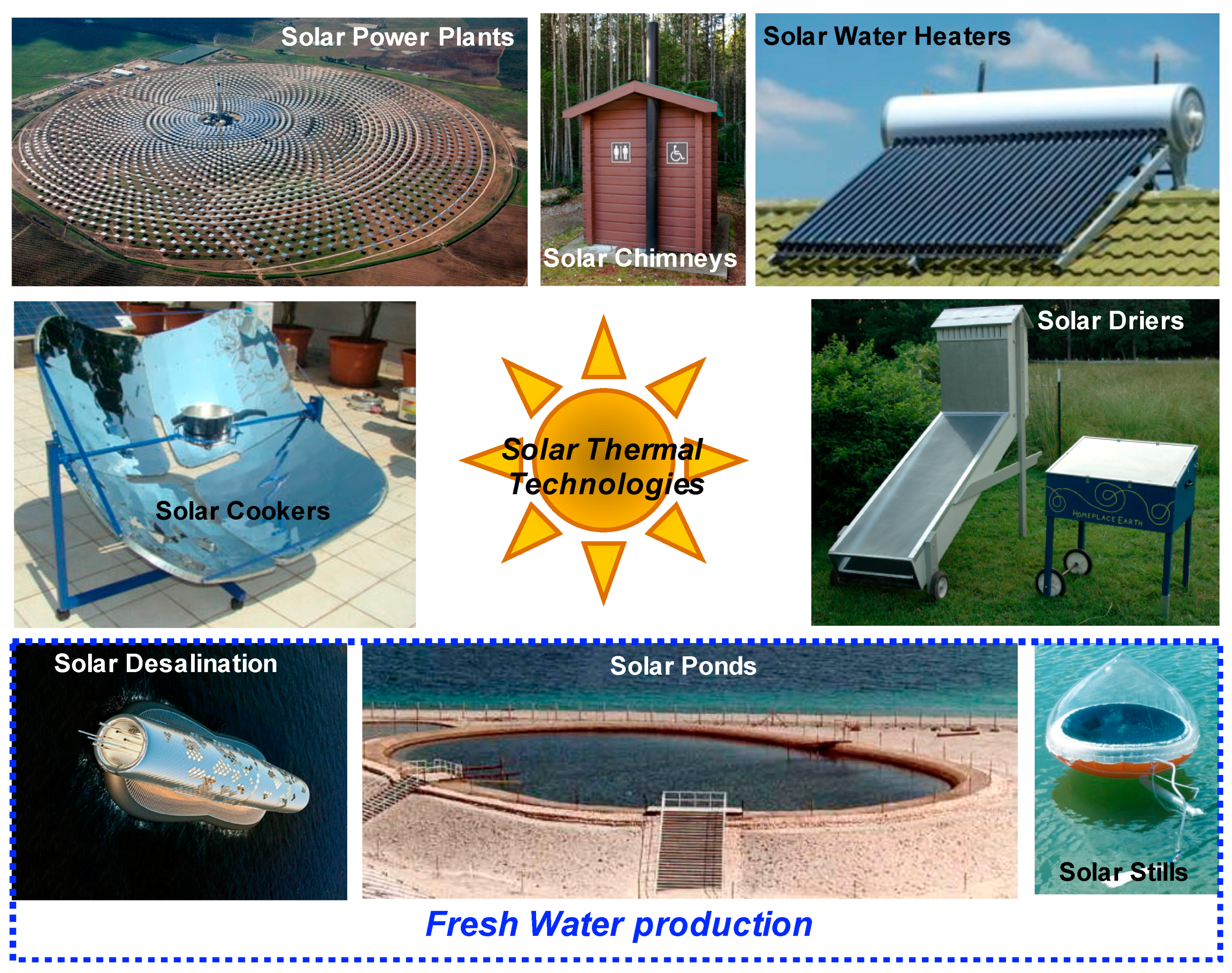
Figure 2.
The phenomenon involved in plasmon-based solar receivers for steam generation.

Figure 3.
(a) Extinction spectra of gold-shell silica-core nanoshells with different shell thicknesses. (b) Extinction spectra of two gold-shell dielectric-core nanoshells with different gap width, inset shows the formation of hotspot between the nanoparticles. (c) Electric field distribution of nanoshells randomly distributed in water under irradiance of the light from air. The analysis is presented using FDTD simulations. (d) Schematic presentation of illumination of 808 nm laser light to the dense solution of nanoparticles contained in a cuvette; multiparticle optical interactions (scattering/absorption) in such nanofluids (right). (e) Experimentally obtained and Monte Carlo simulated scattered light as viewed from the side of cuvettes containing nanoshell solutions of the indicated concentrations [38]. Reprinted with permission from [38]. Copyright (2014) American Chemical Society.
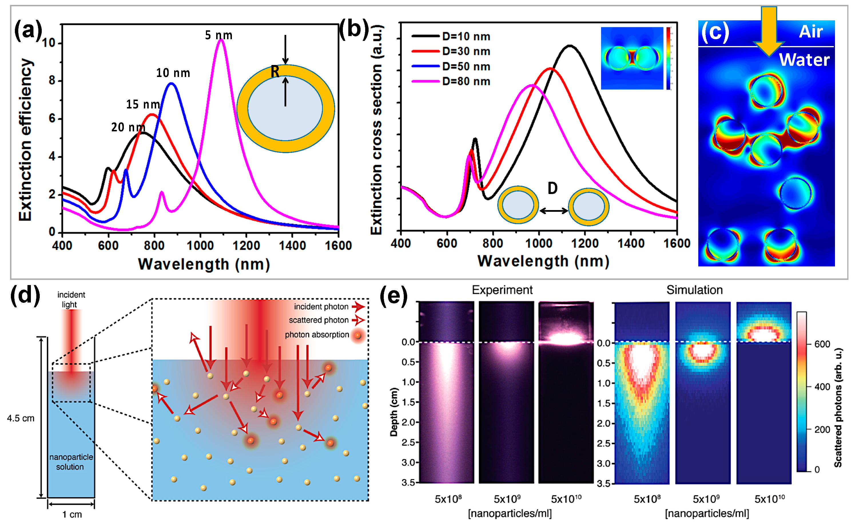
Figure 4.
(a) Optical generation and detection of plasmonic nanobubbles [42]. (b) Dependence of the plasmonic nanobubble (PNB) lifetime (TPNB, red) and the generation probability (black) around single 90 nm gold spheres upon the influence of a single pump laser pulse (0.5 ns, 532 nm) [42]; Reprinted with permission from [42]. Copyright (2010) American Chemical Society. (c) Schematic of nanoparticle-enabled solar steam generation. (d) The absorption cross section of the gold nanoshells is tuned to overlap the solar spectral irradiance (AM 1.5 G) [39]. Reprinted with permission from [39]. Copyright (2013) American Chemical Society. (e) Mass change in transient conditions and (f) transient efficiency as a function of time for the carbon black (CB), graphitized carbon black (GCB), and graphene nanofluids while illuminated by 10 sun of solar irradiance(Qs = 10 kW m−2). Inset of Figure (f) shown the SEM image of carbon black particles [43]. Reprinted with permission from [43]. Copyright (2015) Elsevier.
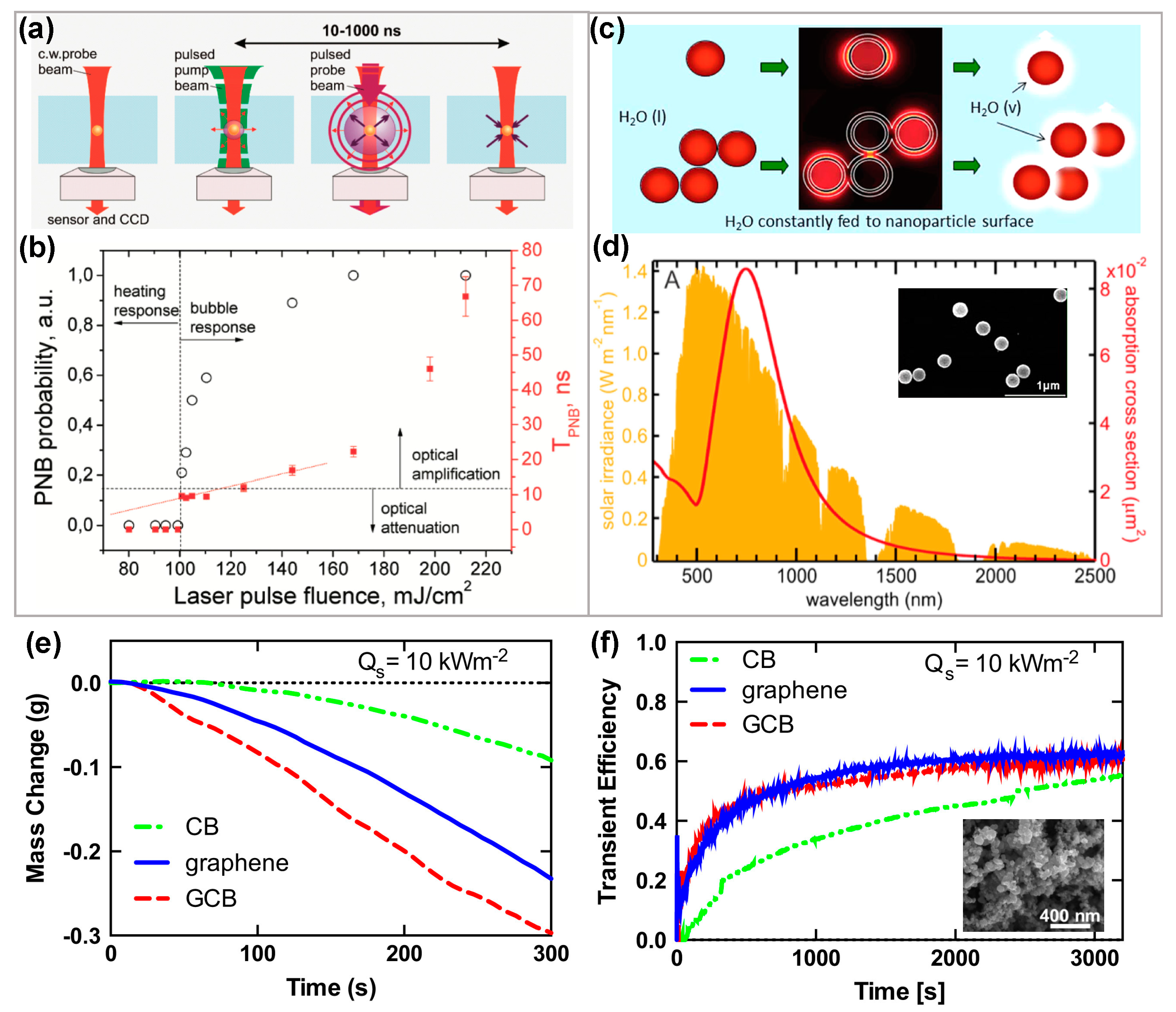
Figure 5.
(a) The schematics of fabrication procedure of ultrathin lm Ge/Au nanoporous absorber. (b) Light absorption properties of ultrathin Ge/Au films are enhanced by nanoholes with different radius. (c) The dependence of absorption on pore shapes with the same pore area [71]. Reprinted with permission from [71]. Copyright (2016) WILEY-VCH Verlag GmbH & Co. KGaA, Weinheim. (d,e) Schematics of self-formed topping nanoparticles nanocomposite absorber and their absorption spectra with different nanocomposite filling factors. (f) The comparisons of the FDTD predicted absorption spectra of the ultrathin nanocomposite absorbers with and without topping Ag nano- particles. The dense and sparse distributions of topping Ag nanoparticles are simulated with 60, 70, and 100 nm of periodicity, respectively [72]. Reprinted with permission from [72]. Copyright (2017) WILEY-VCH Verlag GmbH & Co. KGaA, Weinheim.

Figure 6.
(a) An ideal absorption profile to achieve the maximum solar absorptance while having minimal thermal radiation [73]. Reprinted with permission from [73]. Copyright (2014) Royal Society of Chemistry. (b) In near vacuum conditions (hconv = 0.1 W m−2 K−1), the dependence of solar absorber temperature and solar absorptance performance (the thermal emittance is fixed at 0.1). (c) Dependence of solar absorber temperature and thermal radiation under different heat convection, (d) Relations among solar absorber temperature, their thermal radiation and solar absorptance. (e) Dependence of water mass change and thermal concentration under different thermal emittance.

Figure 7.
(a) Evaporative heat flux normalized by the membrane area plotted against the superheat and expected transition to pore-level evaporation. The schematics depict the liquid in the flooding and pore-level regimes [79]. Reprinted with permission from [79]. Copyright (2017) AIP Publishing LLC. (b) The variation of the evaporative mass flux loss with time as a function of increased molarity of nitric acid, which was used to enhance the hydrophilic character of the wick surface. (c) The inferred variation in the meniscus shape indicating an increased evaporative thin film region, due to enhanced surface hydrophilicity through larger nitric acid molarity (15.8 M vs. 1 M) treatment of the carbon foam surface [81]. Reprinted from [81]. Copyright (2016) AIP Publishing LLC.

Figure 8.
(a) Schematic presentation of the photocatalytic process under UV light irradiance [83]. Reprinted with permission from [83]. Copyright (2015) Elsevier. (b) Proposed mechanism for the degradation of microcystin-LR using reduced graphene oxide-TiO2 under solar irradiance [89]. Reprinted with permission from [89]. Copyright (2013) American Chemical Society. (c) The predicted absorptance spectra of thin films of 120 nm thick TiO2 on glass, Cu, and 500 nm thick CuO/Cu substrates. (d) The spectral absorptance of MB(aq) degradation using TiO2 nanostructures on copper substrate under direct sun light irradiance for 2 h, respectively [90]. Reprinted from [90]. Copyright (2016) by Nature Publishing Group.

Figure 9.
(a) SEM image of the surface with non-uniform nanostructure density. (b) Tilted ESEM image of the early stage condensation on the superhydrophobic surface with non-uniform nanostructure density [94]. (c) Illustration of the droplet nucleation, growth, partial depinning, and coalescence jumping processes. Reprinted from [94]. Copyright (2017) by ASME. (d) The effect of surface wettability on the jumping velocity of different droplet sizes [95]. Reprinted from [95]. Copyright (2017) by American Chemical Society.

Figure 10.
(a) A representative structure for localization of heat; the cross section of structure and temperature distribution of double layered structure (DLS) [96]. (b) The reflectance of the DLS in the wavelength range of 250–2250 nm. (c) The solar thermal efficiency of the evaporation process by the DLS under a range of optical concentrations and the corresponding evaporation rate. Inset picture of (c) shows the steam generation by DLS under the solar irradiance of 10 kW m−2. Reprinted with permission from [96]. Copyright (2014) by Nature Publishing Group (d) Schematic illustration of heat localization system to convert sunlight into steam using a single layer of porous N-doped graphene [98]. (e) Total reflectance spectra and transmittance of the graphene foam in the wavelength range of 250–2000 nm. Inset of (e) shows the SEM image of graphene foam. (f) The temperature rise of porous graphene samples under concentrated 1 kW m−2 solar irradiance. Reprinted with permission from [98]. Copyright (2015) WILEY-VCH Verlag GmbH & Co. KGaA, Weinheim.

Figure 11.
(a) Schematic illustration of 3D printing process. Carbon nanotubes (CNT), Graphene oxide (GO), and nano fibrillated cellulose (NFC). (b) Temperature distribution of the wet 3D-printed evaporator (3D-CG/GN) used for simulating and calculating the equivalent thermal conductivity. (c) Curves of dynamic evaporation rate of pure water and the 3D-CG/GN at different time points [105]. Reprinted from [105]. Copyright (2017) WILEY-VCH Verlag GmbH & Co. KGaA, Weinheim.
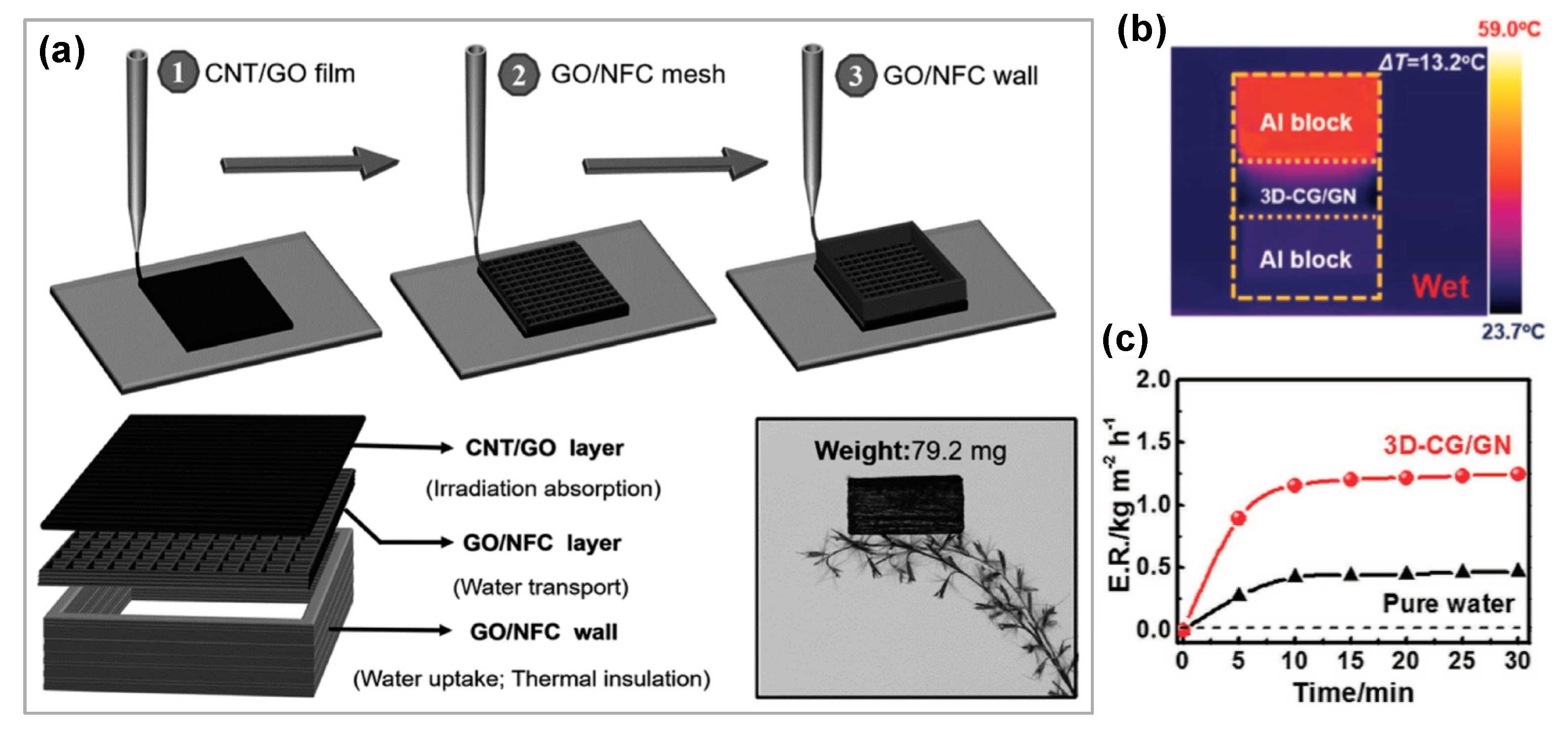
Figure 12.
(a) Proposed reactions during the isocyanate treatment of graphene oxide [106]. (b) SEM image of reduced graphene oxide/poly urethane nanocomposite. (c) The temperature changes before and after solar irradiance monitored by IR camera. Reprinted with permission from [106]. Copyright (2017) by American Chemical Society. (d) Schematic of the fabrication process of graphene oxide-cellulose ester membranes PEI-GO-MCE) using polyethylenimine as a crosslinking agent [107]. (e) The temperature changes before and after solar irradiance monitored by IR camera. Reprinted with permission from [107]. Copyright (2016) by Elsevier Ltd.

Figure 13.
Mushroom-based solar steam generation. (a) Schematic of a mushroom-based solar steam-generation device [110]. (b) Physical picture of a shiitake mushroom. (c) Physical picture of a mushroom after carbonization. Reprinted with permission from [110]. Copyright (2017) WILEY-VCH Verlag GmbH & Co. KGaA, Weinheim. (d) Graphical illustration of the flexible solar steam made from carbon nanotube coated flexible wood membrane [111]. Reprinted with permission from [111]. Copyright (2017) WILEY-VCH Verlag GmbH & Co. KGaA, Weinheim.
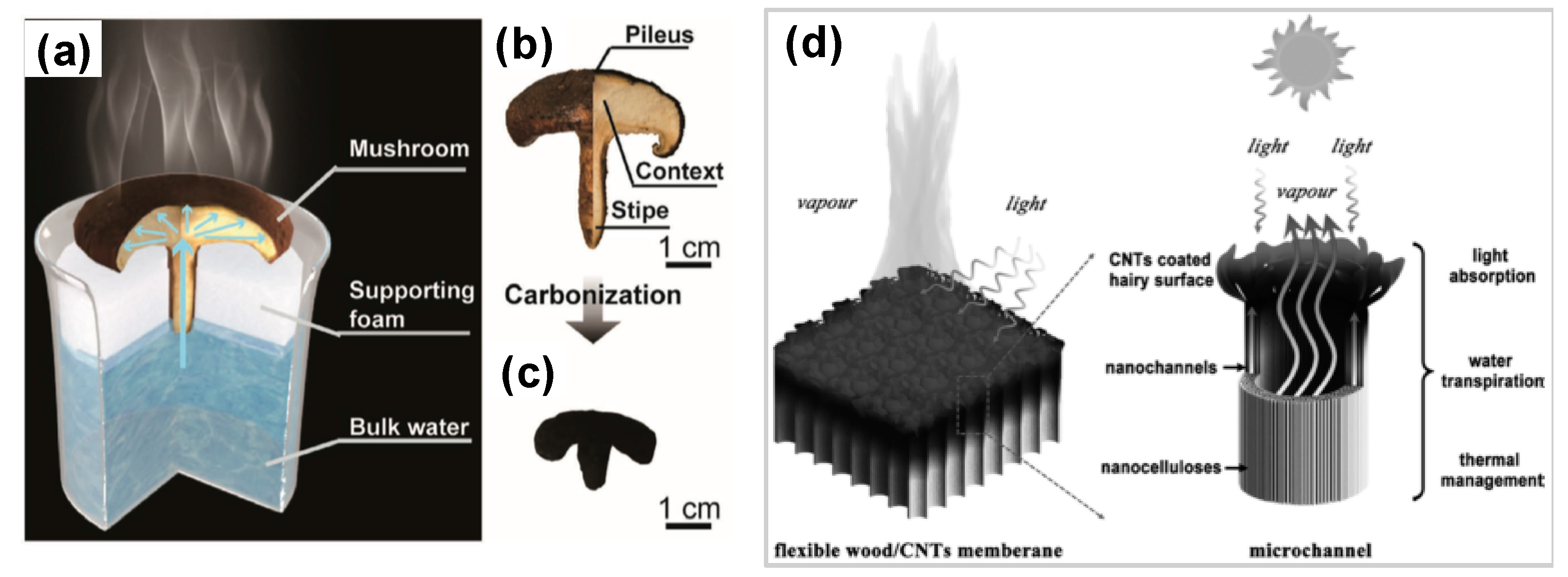
Figure 14.
(a) High-resolution SEM images of aluminum-based plasmonic membranes: the top and cross-section view [117]. (b) Experimental and simulated absorption of aluminum-based plasmonic absorbers (400–2500 nm). The normalized spectral solar irradiance density of air mass 1.5 global (AM 1.5 G) solar spectrum is shown by the blue dashed line. (c) The measured concentrations of four primary ions in an actual seawater sample (average salinity ∼2.75 wt %) before and after desalination. Reprinted with permission from [117]. Copyright (2016) by Nature Publishing Group. The purple (green) shaded area refers to the overall typical salinity achieved by traditional membrane (distillation) desalination process, respectively. (d) SEM cross sectional image of vertically aligned graphene membranes inset image shows the schematics water transport behavior [114]. (e,f) Solar thermal conversion efficiency and measured concentrations of five primary ions in an actual seawater sample before and after purification using vertically aligned graphene membranes. Reprinted with permission from [114]. Copyright (2016) by American Chemical Society.

Figure 15.
(a) The pilot project of enclosed-trough solar thermal design. (b) Schematics of enclosed trough solar system with different parts [125]. Reprinted with permission from [125]. Copyright (2014) Published by Elsevier Ltd. (c) Overview of typical operating day [126]. Reproduced image from the web link of [126].

Figure 16.
(a) Energy balance and heat transfer in the developed one-sun, ambient steam generator. (b) Comparison of thermal radiative losses at 100 °C from a blackbody and the spectrally selective absorber. (c) Steady-state vapor and selective absorber temperatures measured as a function of the thermal concentration used. The evaporation slots were varied in size to control the operating temperature [127]. Reprinted from [127]. Copyright (2016) by Nature Publishing Group.
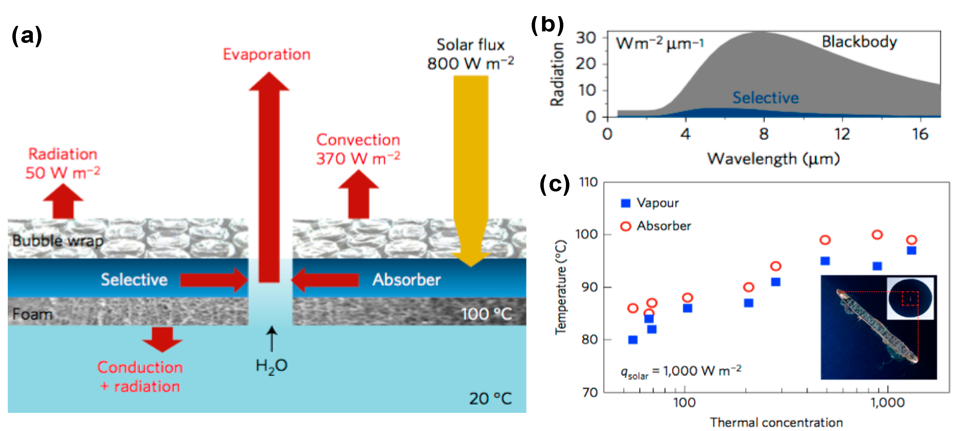
Figure 17.
(a) Schematics of the setup used for lab scale steam generation experiments. (b,c) High resolution SEM images of copper oxide nanostructures on copper substrate with etching time of 90 s and 600 s, respectively. Comparison of UV-Visible-nIR (d) and FT-IR (e) spectra of bare copper, CuO/Cu BA, and CuO/Cu SA. The inset in (d) shows the solar spectrum for reference.

Figure 18.
(a) 1D model to predict the effect of thermal concentration on the vapor temperature by considering possible heat losses. (b) The temperature profiles measured at the surface of the various samples at the irradiance intensity of 1 KW m−2. (c) Comparison of accelerated water mass change due to evaporation with time.
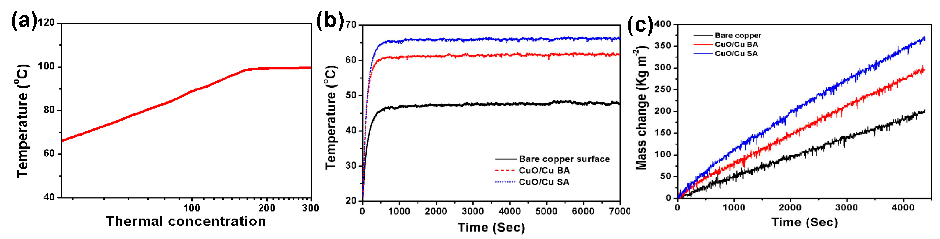
Figure 19.
(a,b) Temperature distributions on the side and subsurface of the solar absorber. (c–e) Influence of slot distribution on the temperature profile.
Figure 19.
(a,b) Temperature distributions on the side and subsurface of the solar absorber. (c–e) Influence of slot distribution on the temperature profile.


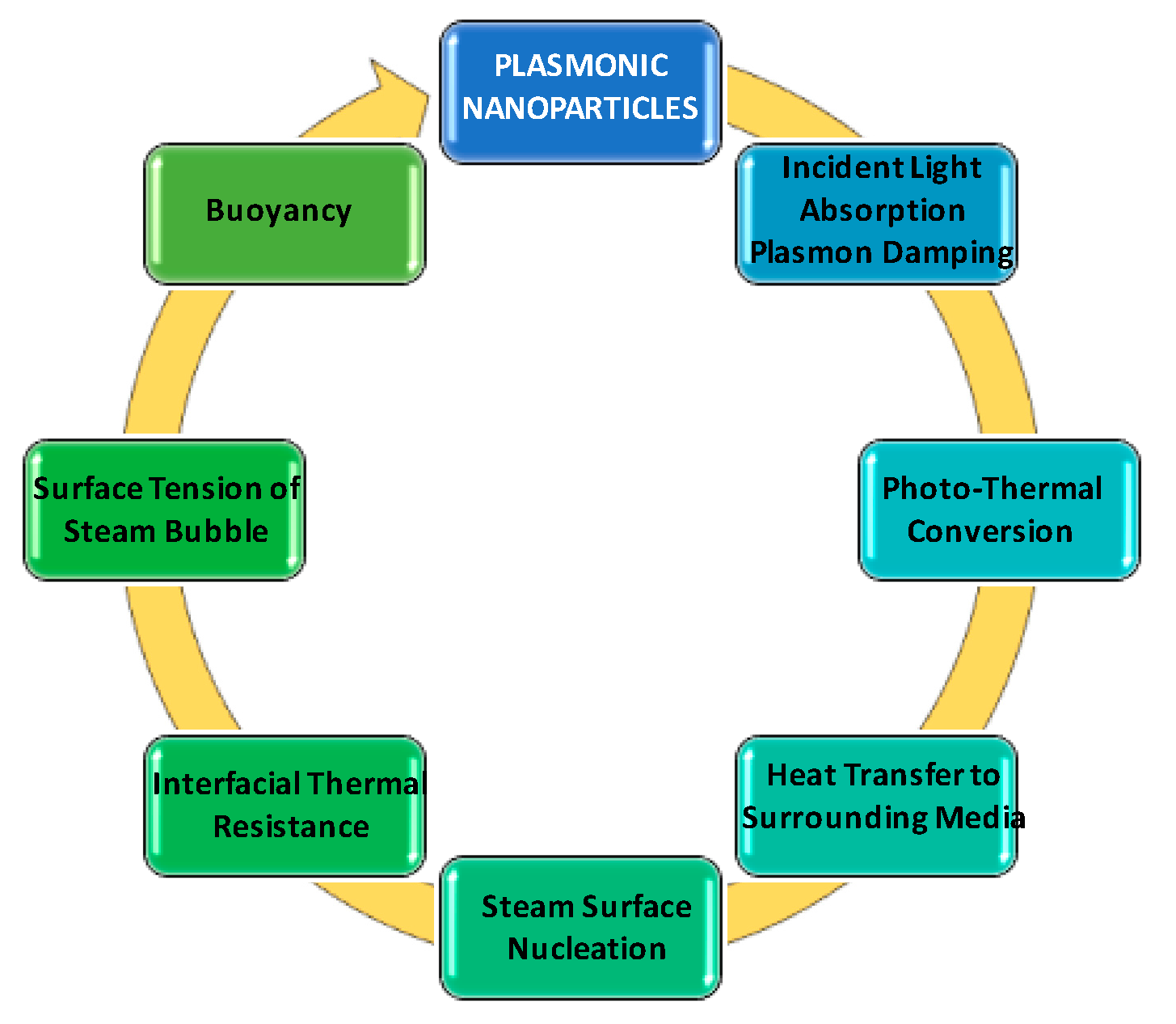
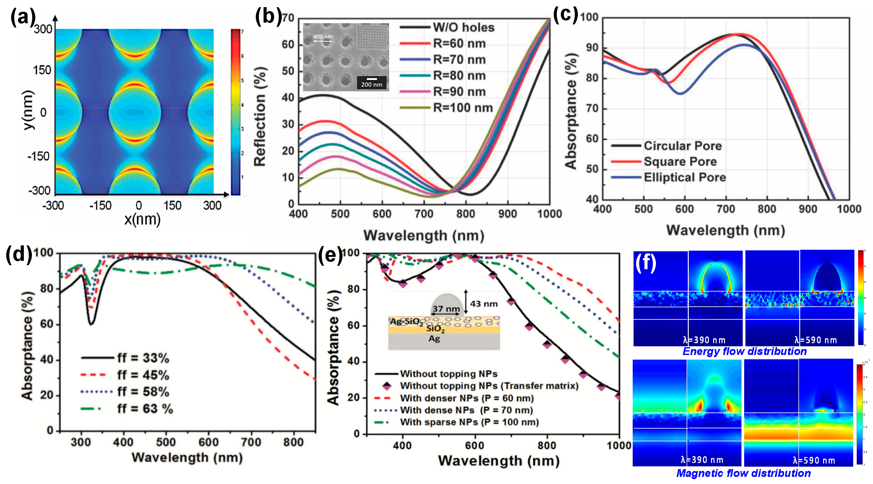
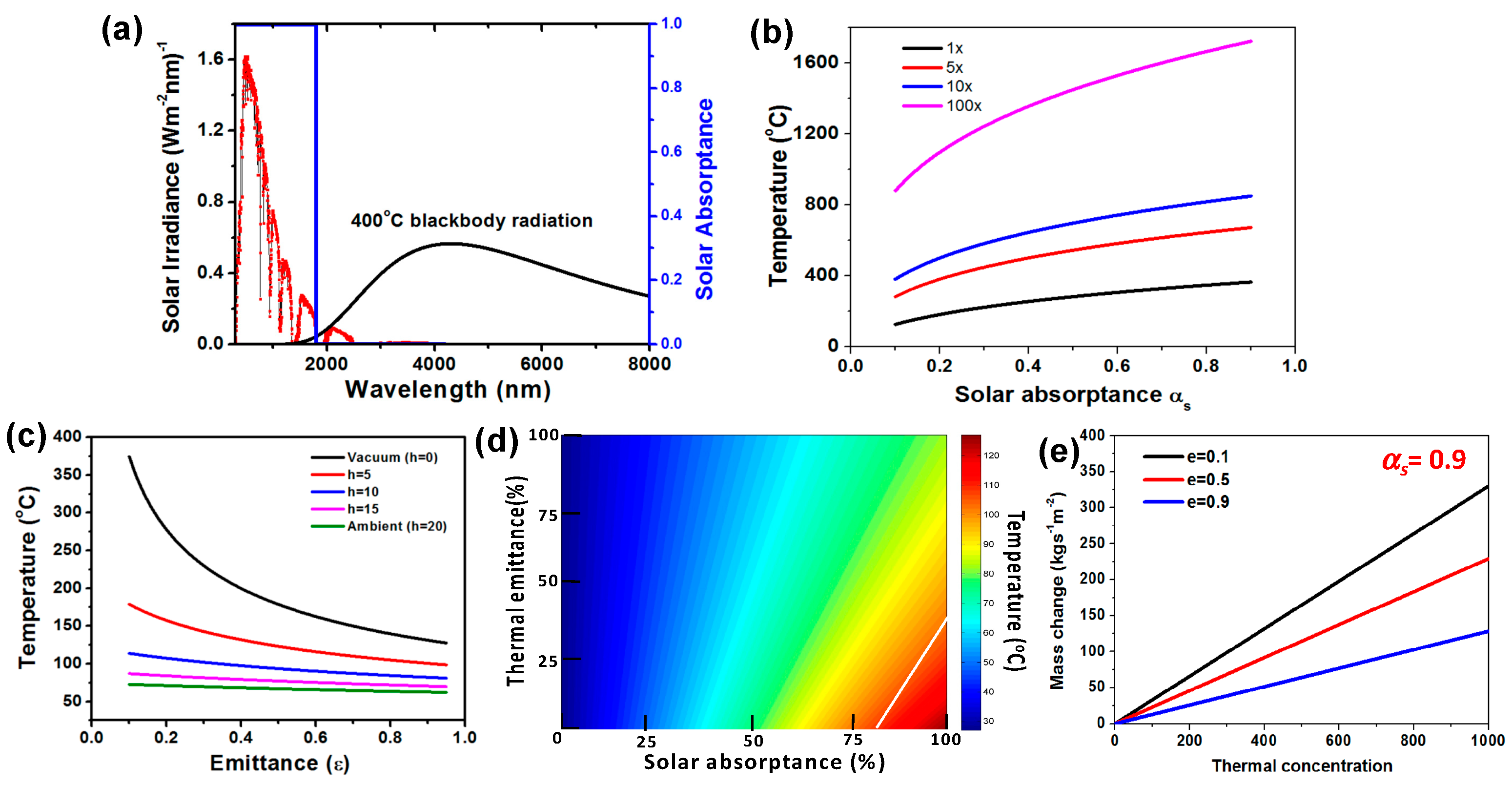
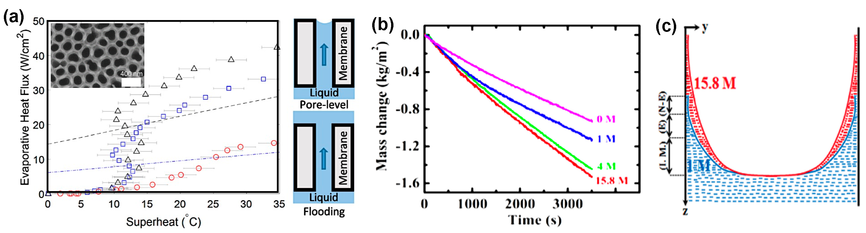
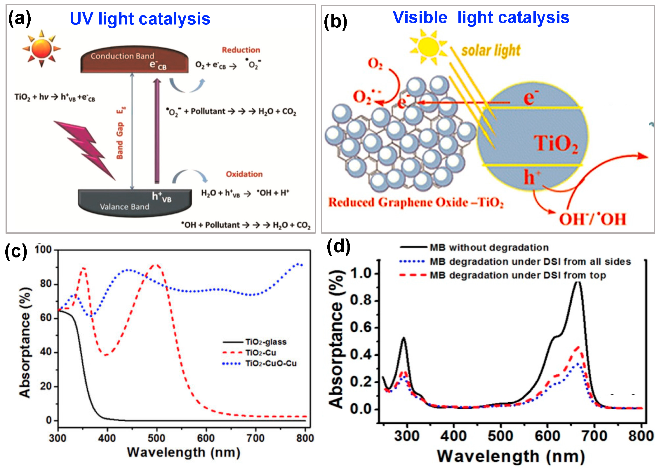
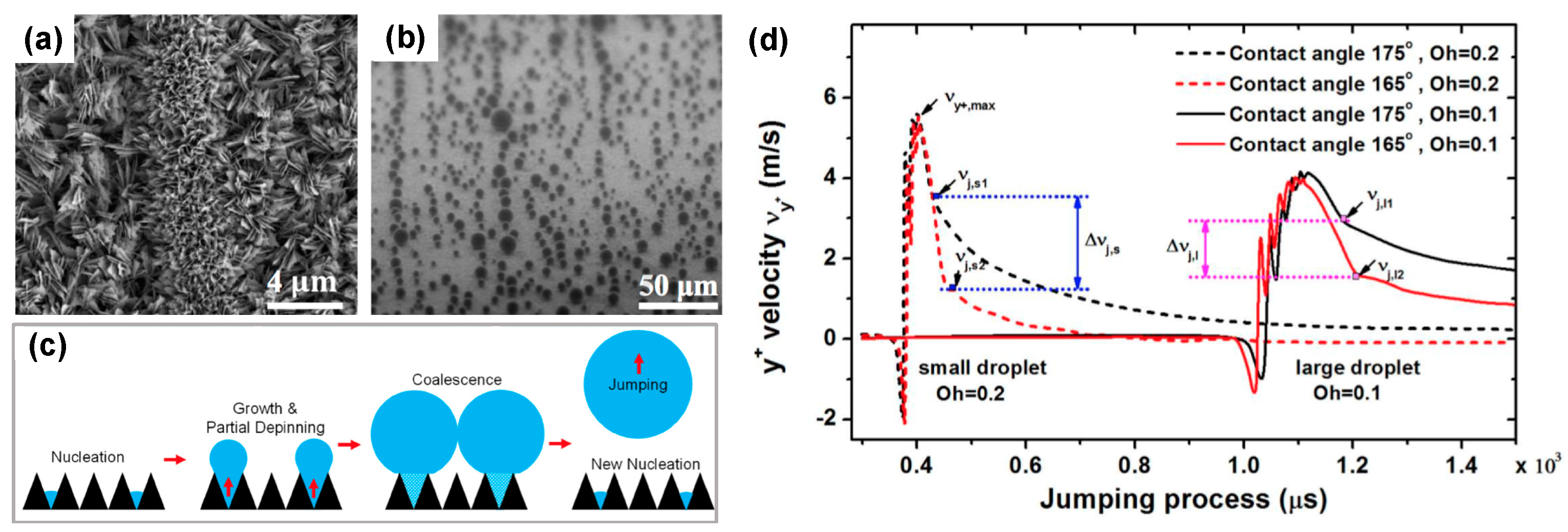
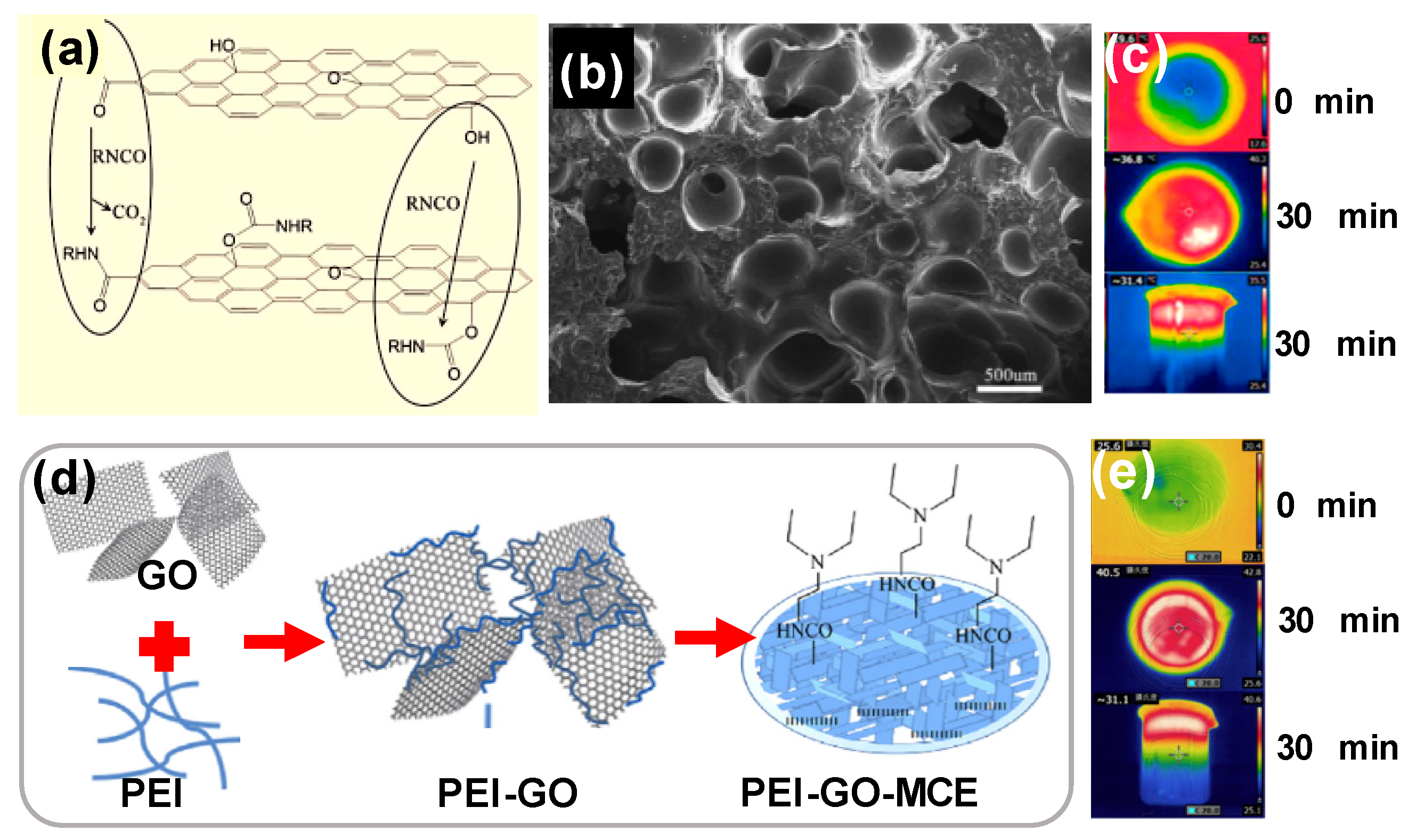
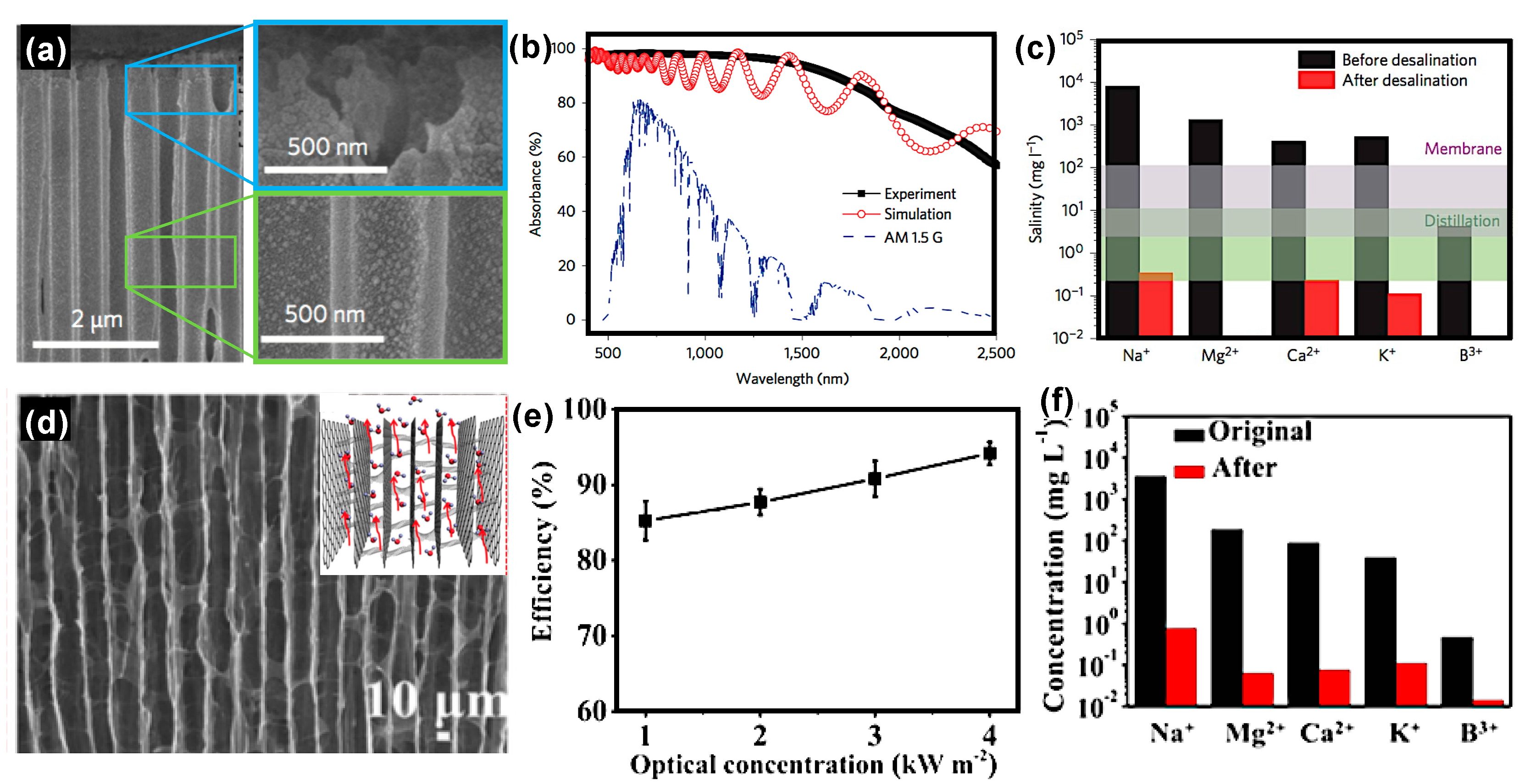
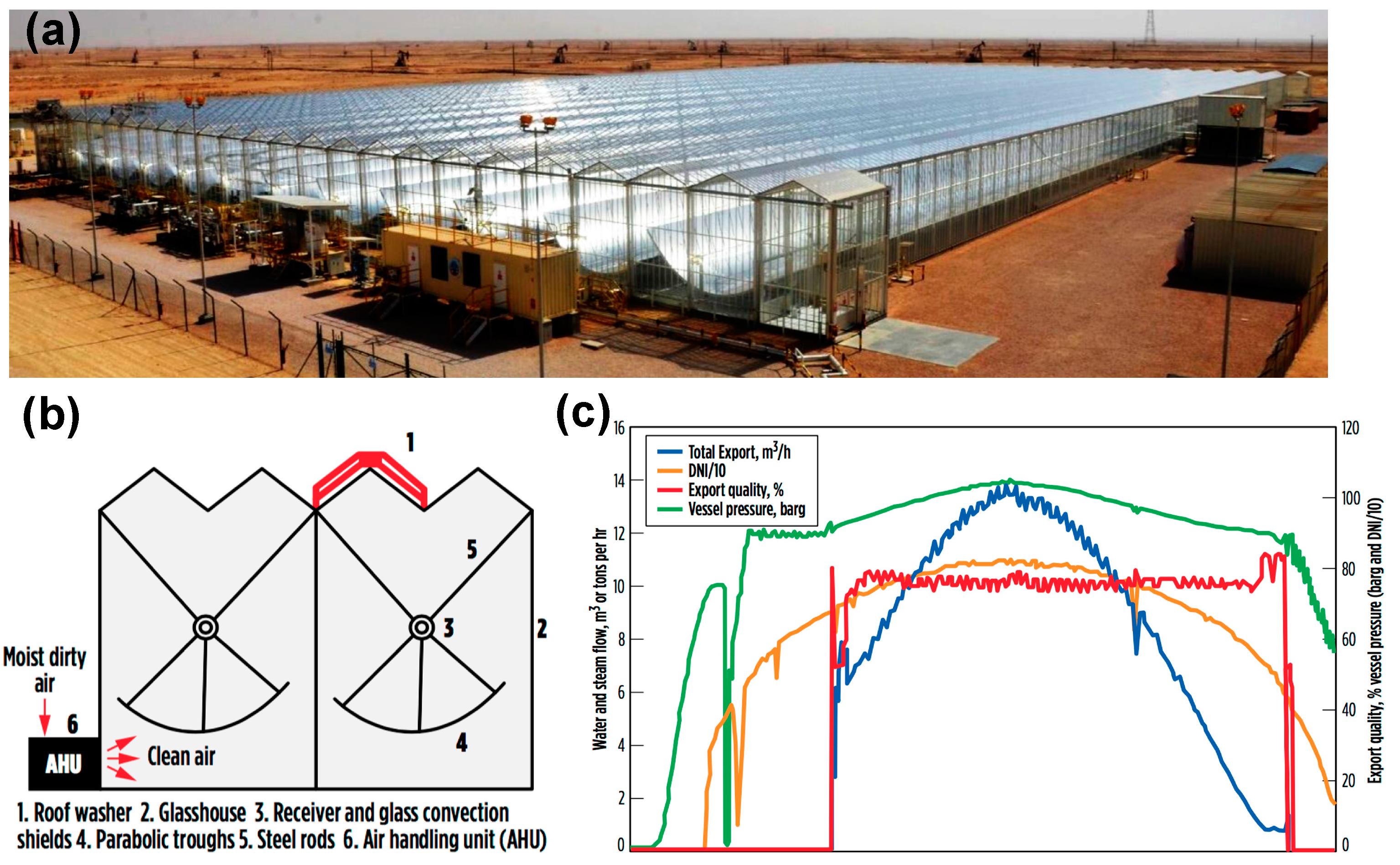
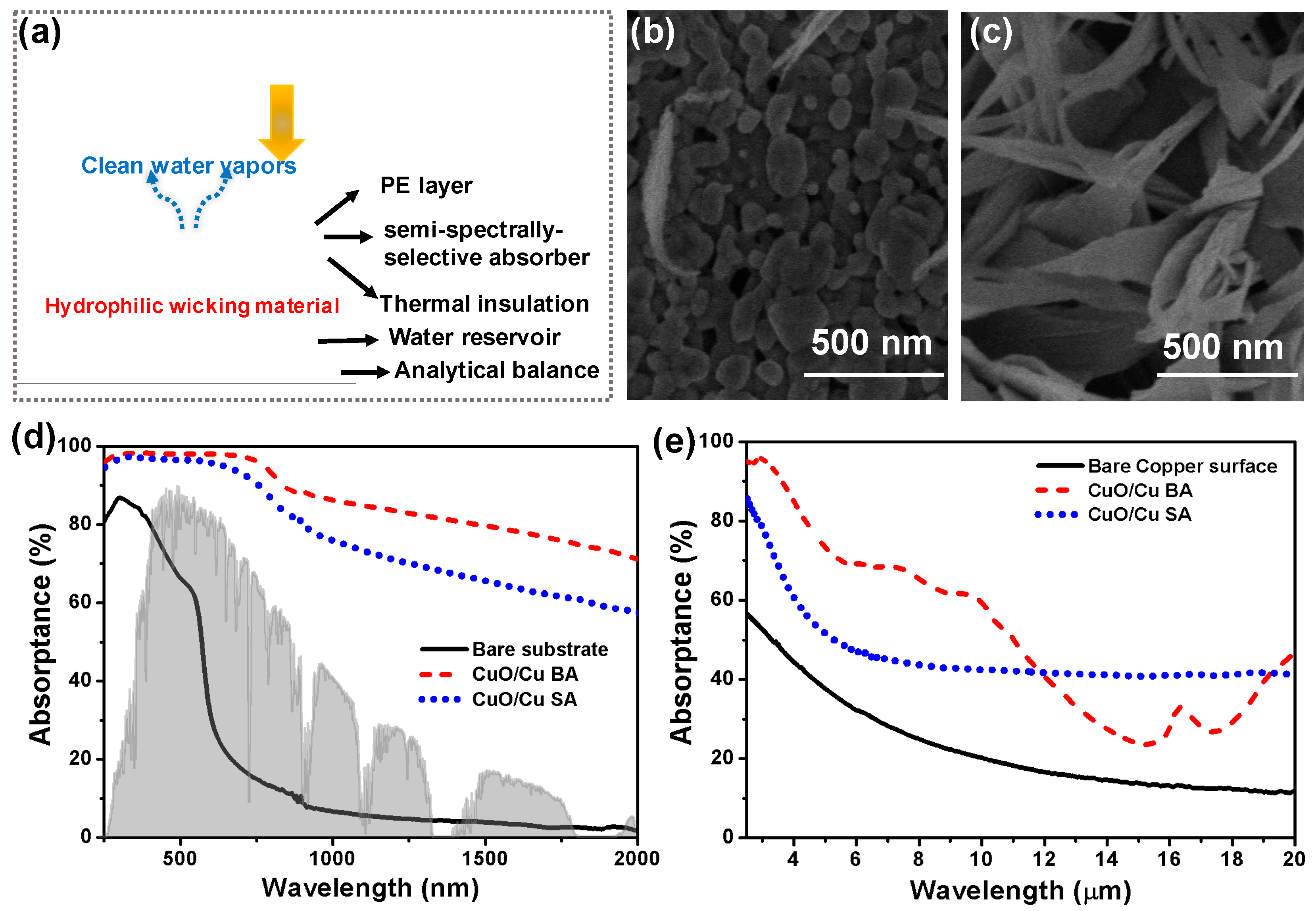
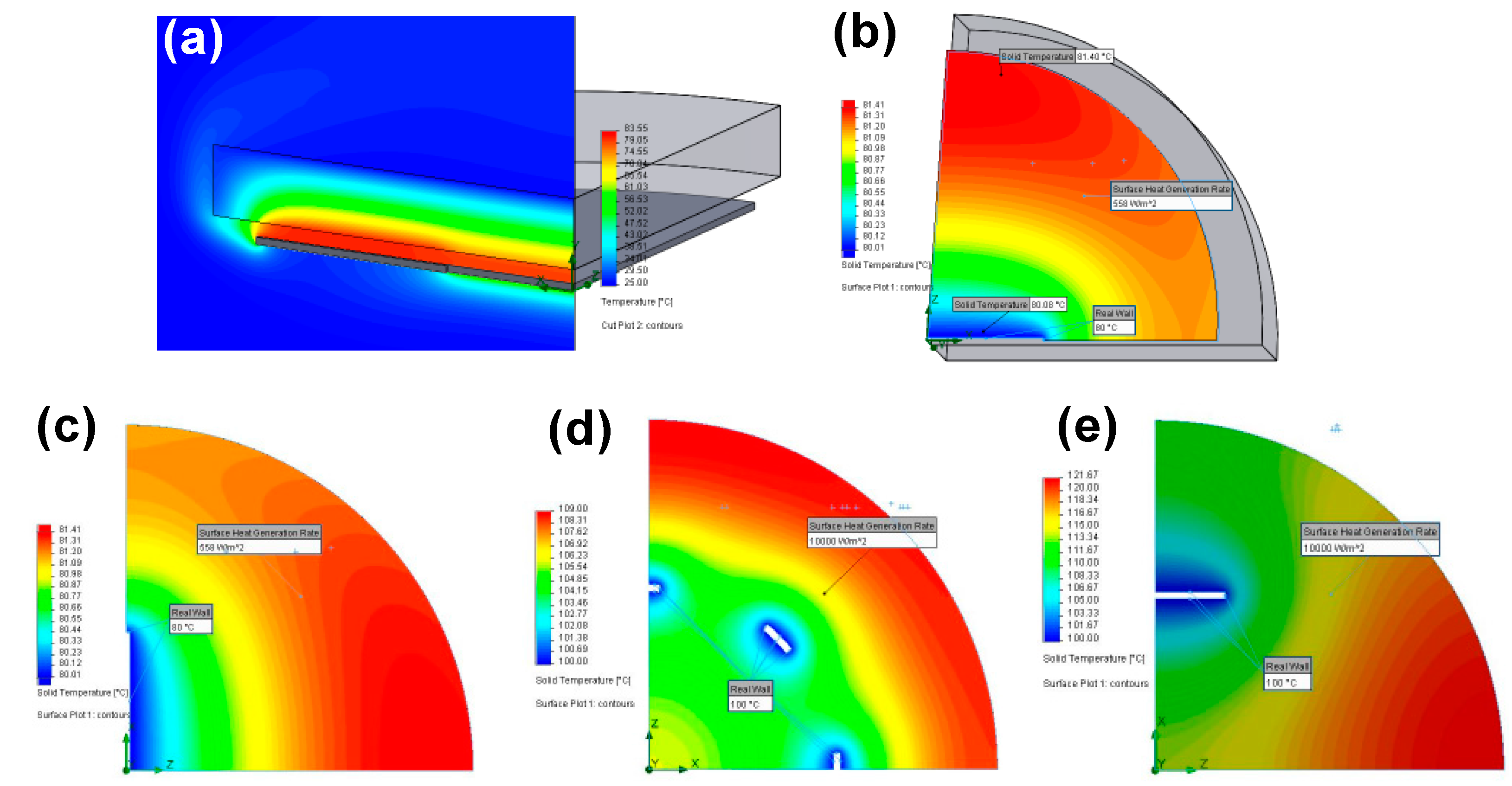
Table 1.
Thermal conductivities and solar thermal conversion efficiency of various materials under 1 sun solar irradiance (1 kW m−2).
Table 1.
Thermal conductivities and solar thermal conversion efficiency of various materials under 1 sun solar irradiance (1 kW m−2).
| Materials | Thermal Conductivity | Energy Conversion | References |
|---|---|---|---|
| W m−1 K−1 | % | ||
| Porous graphene | 94 ± 5.2 | 46 | [107] |
| Porous N-doped graphene | 9.0 ± 1.2 | 54 | [98] |
| Graphite | 119–165 | 56 | [43] |
| Activated carbon fiber | 21–125 | - | [98] |
| Carbon nanotubes-Balsa wood | 0.21 | 65 | [111] |
| Reduced graphene oxide-polyurethane | 1.0984 | 65 | [106] |
| Reduced graphene oxide- cellulose ester membranes | 4 4.466 | 52 | [107] |
| Vertically aligned graphene sheet membranes | 0.0038 | 86.5 | [114] |
| Carbonized mushrooms | 0.45 | 78 | [110] |
Table 2.
The steam temperature using various materials under simulated solar irradiances.
| Materials | Solar Irradiance (kW m−2) | Steam Temperature (°C) | Reference |
|---|---|---|---|
| Reduced graphene oxide-Fe3O4 | 1 | 47 | [56] |
| Reduced graphene oxide-Fe3O4 | 2 | 56 | [56] |
| Au nanoparticles | 220 | 100 | [44] |
| Au nanoparticles-graphene | 0.7 | 27.2 | [57] |
| Vertically aligned carbon nanotubes | 15 | 60 | [104] |
| Polyurethane-Reduced graphene oxide | 1 | 31.4 | [106] |
| Polyurethane-Reduced graphene oxide | 10 | 67.8 | [106] |
| Reduced graphene oxide +MCE | 4 | 40.5 | [107] |
| Reduced graphene oxide bilayer | 10 | 80 | [108] |
| Carbonized mushroom | 1 | 40 | [110] |
| CNTs modified balsa wood | 1 | 36 | [111] |
| CuO/Cu SA | 1 | 67 | This work |
© 2018 by the authors. Licensee MDPI, Basel, Switzerland. This article is an open access article distributed under the terms and conditions of the Creative Commons Attribution (CC BY) license (http://creativecommons.org/licenses/by/4.0/).
Share and Cite
MDPI and ACS Style
Raza, A.; Lu, J.-Y.; Alzaim, S.; Li, H.; Zhang, T. Novel Receiver-Enhanced Solar Vapor Generation: Review and Perspectives. Energies 2018, 11, 253. https://doi.org/10.3390/en11010253
AMA Style
Raza A, Lu J-Y, Alzaim S, Li H, Zhang T. Novel Receiver-Enhanced Solar Vapor Generation: Review and Perspectives. Energies. 2018; 11(1):253. https://doi.org/10.3390/en11010253
Chicago/Turabian StyleRaza, Aikifa, Jin-You Lu, Safa Alzaim, Hongxia Li, and TieJun Zhang. 2018. "Novel Receiver-Enhanced Solar Vapor Generation: Review and Perspectives" Energies 11, no. 1: 253. https://doi.org/10.3390/en11010253
Note that from the first issue of 2016, this journal uses article numbers instead of page numbers. See further details here.