The Innovative Concept of Cold District Heating Networks: A Literature Review


Department of Industrial Engineering (DIN), University of Bologna, Via Fontanelle 40, 47121 Forlì, Italy
*
Author to whom correspondence should be addressed.
Energies 2018, 11(1), 236; https://doi.org/10.3390/en11010236
Submission received: 22 December 2017
/
Revised: 16 January 2018
/
Accepted: 16 January 2018
/
Published: 19 January 2018
Abstract
:The development of sustainable and innovative solutions for the production and supply of energy at district level is nowadays one of the main technical challenges. In the past, district heating and cooling networks aimed to achieve greater energy efficiency through the centralization of the energy production process but with relevant losses related to heat transport. Moving towards a higher share of renewables and lower demand of primary energy requires redesign of the energy district networks. The novel concept of cold district heating networks aims to combine the advantages of a centralized energy distribution system with low heat losses in energy supply. This combined effect is achieved through the centralized supply of water at relatively low temperatures (in the range 10–25 °C), which is then heated up by decentralized heat pumps. Moreover, cold district heating networks are also very suitable for cooling delivery, since cold water supplying can be directly used for cooling purposes (i.e., free cooling) or to feed decentralized chillers with very high energy efficiency ratio. This paper provides a preliminary literature review of existing cold district heating networks and then qualitatively analyses benefits and drawbacks in comparison with the alternatives currently used to produce heat and cold at district level, including the evaluation of major barriers to its further development.
1. Introduction
The integration and implementation of renewable energy systems at district scale is described in a number of recent reports and studies, including [1,2,3,4,5,6]. District heating and cooling networks play an important role in the task of increasing renewable energy exploitation and the development of novel design approaches, while business models are crucial to meet future demands for a higher level of efficiency and lower environmental impact of energy production, supply and use at district level. The idea of district heating was developed to provide greater efficiency and better environmental impact than localized boilers through the centralized production of heat and its distribution to final users (usually both residential and commercial) by a network of pipes [7]. The pipeline network can be designed in different ways, including ring networks, branched networks and looped networks [8]. The so called 1st generation of district heating networks was introduced in the late 19th century in the US, using steam as a heat carrier. These systems were replaced by 2nd generation networks, which use pressurized hot water with supply temperatures over 100 °C as a heat carrier. Since space heating in traditional residential buildings has generally been ensured by heat transfer from radiators at about 80 °C supply temperature, district heating networks with lower supply temperatures were therefore established in the market starting from the 1970s, i.e., the so called 3rd generation of district heating systems, which are currently and widely applied [9]: the total number of systems has been estimated at 80,000 systems worldwide, of which about 6000 systems (7.5%) in Europe. Third generation district heating systems are characterized by using pressurized hot water as a heat carrier but with lower temperatures (below 100 °C) than 2nd generation systems.
The higher efficiency in energy production due to centralization in comparison with decentralized systems has a drawback in distribution losses, which are usually in the range of 10–30% [10,11] and in the costs related to distribution pipeline insulation [12,13]. Furthermore, high temperature-sustaining materials (i.e., steel) must be used for the network [14], including heat exchangers, valves and instrumentations. Moreover, integration in the network is suitable only for high temperature sources, thus limiting the possibility of renewables exploitation [15,16]. Finally, in the last few years the improvement in building energy performance and in the retrofitting of building stock contributes to a generalized decrease in heating demand [17,18]. This fact produces an increase of the relative distribution losses and a decrease of the overall cost effectiveness of existing district heating networks.
A further reduction of heat supply temperatures has been identified as one of the possible solutions. This so-called 4th generation of district heating networks is a novel and quite recent district heating concept developed in Denmark [19] and characterized by lower temperatures. The temperature decrease in the network can lead to (i) an increase of efficiency of district heating systems due to reduction of heat losses and (ii) can allow easier integration of cost-efficient renewable energy technologies (like solar energy or geothermal heat pumps) which are not linked to combustion processes. A further division of 4th generation systems can be made between so-called low temperature district heating (LTDH) and ultra-low temperature district heating (ULTDH). LTDH networks are usually characterized by supply temperatures in the range 50–70 °C, while ULTDH networks have supply temperatures below 50 °C, without a common definition of lower limit [20]. In ULTDH networks, decentralized micro-heat power stations should be used to boost the domestic hot water (DHW) temperature as needed [21]. Another advantage of 4th generation systems is the possibility of using cheaper materials like plastic for pipes and other network components, including also a relevant decrease of insulator thickness and related costs.
Although the idea has only recently been developed, a considerable amount of literature can be found on 4th generation or low temperature district heating. Qualitative benefits and drawback analysis have been assessed [22,23,24], including the evaluation of how 4th district heating systems can be integrated into the smart city concept. Further specific analysis has been carried out to identify how technical [25,26,27], legislative [28,29] and economic [30,31] barriers can be overcome. Case studies from different countries have also been reported [20,32,33,34]. Nevertheless, the development of 4th generation systems of district heating is characterized by two strong limitations: the first is that the demand side of a district heating network consists of buildings built at different times. This means that they have different thermal loads and, in particular, they use different indoor space heating distribution systems, which require diverse inlet temperature set points. However, heating terminals of existing buildings are usually oversized compared to real needs. Therefore, lower distribution temperatures may be acceptable in some cases and can cover a fraction of the seasonal thermal load [35,36]. The application of 4th generation district heating is thus mainly suitable in new and/or renovated buildings. Secondly, 4th generation as well as traditional district heating systems have low compatibility with district cooling networks. Some authors suggested creating a bidirectional low temperature network [37]. The warmer pipe has temperatures between 12 °C and 20 °C, while the cold pipe has 8–16 °C. In the case of a heating demand, the circulation pump of the building withdraws water from the warm line, uses it in a heat pump to reach temperatures suitable for space heating and then discharges the cooled water to the cold line. In the case of a cooling demand, the system works in the other direction. The system requires a complex regulation of both the energy supply network and the end-users’ substations and does not solve the problem of requiring two pipelines (one for heating and one for cooling). Finally, a great challenge in district heating networks is the hygienic preparation of DHW [38] if supply temperatures fall within a certain range (25–55 °C): to avoid the origin and the proliferation of legionella in a centralized DHW system, minimum temperatures must be guaranteed.
District cooling has been a more recent development compared to district heating: this fact is justified by the greater technologic and non-technologic barriers involved in district cooling in comparison with district heating [39,40]. District cooling systems are therefore neither as common nor as extensive as district heating systems. On the other hand, energy demand for space cooling has grown rapidly since the 90’s: this is confirmed by in the number of central air-conditioners and room air-conditioners installed which increased by more than 50 times from 1990 to 2010 in the European Union [41]. Other parameters which underline this trend are heating degree days and cooling degree days, which have, respectively, decreased and increased in the last 15 years in Europe [42]. Similar trends can be observed in other Countries. So, the combined effect of the decrease in heat demand and the increase in cooling request is making the creation of district heating networks alone, i.e., without cooling, less profitable and reliable. Centralized energy production offers the possibility to combine heat and cold plants, i.e., cogenerative units that electrically feed compressor chillers and/or thermally feed absorption chillers [43]. On the other hand, from an infrastructural point of view the integration between district heating and cooling networks has some techno-economic obstacles. In fact, it is difficult to use only one pipeline for both heating and cooling purposes since the demand for production of DHW may be simultaneous to cooling demand. As a result, the network cost is more or less doubled if compared with district heating alone. A possible alternative is the use of decentralized absorption chillers for the production of cold, the supplying pipeline being a hot network [44,45]: however, in this case, the application of 4th generation district heating networks would be not favoured, since hot water temperatures lower than 85–90 °C produce lower (if any) cooling effect in the absorption chillers.
A possible solution to favour a high degree of integration between district heating and cooling networks, without compromising energy efficiency production and also to reduce thermal losses in the supply network, is the creation of a so-called “cold” district heating (CDH) network. The CDH network concept is based on the circulation of cold water, coming from different sources (surface and deeper aquifers, seawater, wastewater, aqueducts), which is sent to secondary stations where it can be used as condensing and/or evaporating fluid in a heat pump/chiller to produce, respectively, hot water for space heating and/or DHW production and cold water for space cooling. In some cases, the centralized cold water may be used directly as the cooling fluid, thus greatly increasing the system’s efficiency. A CDH network thus always includes the possibility to also deliver cooling energy to the end-users.
The first objective of this paper is to map and analyse the existing CDH networks. Furthermore, the paper aims to qualitatively evaluate, from a techno-economic perspective, the benefits and drawbacks of the innovative CDH model in comparison with the alternatives currently applied to produce and deliver heat and cold at district level, including the evaluation of relevant barriers to its further development. Economic aspects related to energy prices are not directly evaluated in the paper since both electric energy and thermal energy production are affected by local frameworks.
2. Cold District Heating Networks
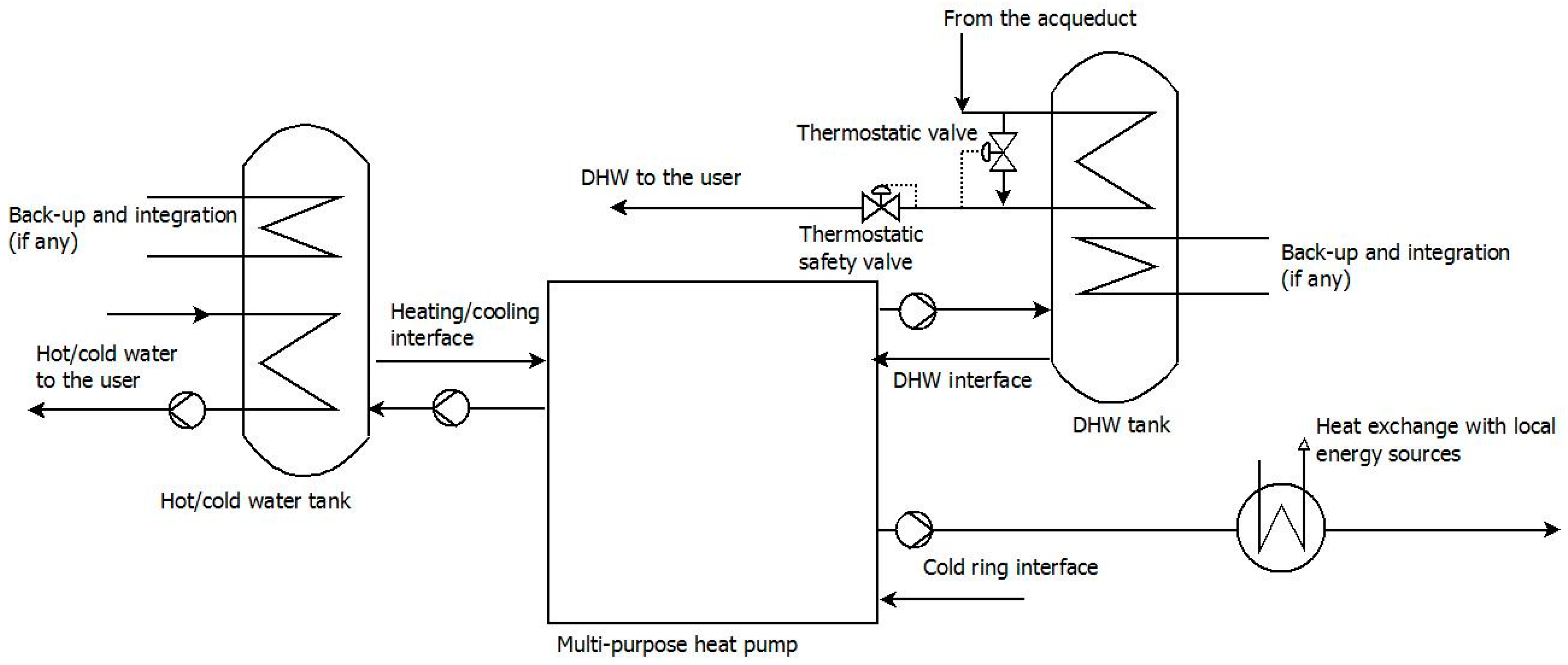
The concept of CDH, even though it can be found in the literature, has not been defined and generally analysed. So, the first aim of this paper is to give a definition of a CDH network (Figure 1), which can be defined as a system for distributing cold water in a temperature range between 10 °C and 25 °C to end-users’ substations where it is used to produce, also simultaneously, hot and cold water at different temperatures and for different purposes (space heating, cooling, DHW production) via heat pumps and chillers. Figure 1 shows two optional configurations: the first concerns the creation of a primary and secondary circuit, thus avoiding a direct energy exchange between the water source(s) and the users’ substations. A second option is the pre-heating of the water flowing through the cold ring (see Section 2.2): this option may be needed when the water source temperature in wintertime is too low. Users can act in three different ways: they can return water to the network which is heated up (user #1 in Figure 1), cooled down (user #2 in Figure 1) or has no temperature variation (user #3 in Figure 1). The last case occurs when the user has an equal energy use for space heating or DHW production and cooling.
A CDH network can be seen as a water-loop heat pump (WLHP) system developed at district level: in fact, a WLHP uses a loop composed of small water-air heat exchangers and through a ring of circulating water in the temperature range 16–32 °C it can simultaneously provide heating and cooling for different areas of one building. The WLHP has been successfully applied in many countries and has shown a high rate of energy saving potential and interesting payback time [46,47]. On the other hand, WLHP system effectiveness is strictly related to the possibility of perfectly balancing heating and cooling demand. When a balance is not possible, it is necessary to integrate the loop with a heat rejecter (i.e., cooling tower or geothermal heat exchanger), heat adder (i.e., boiler or geothermal heat exchanger) or energy storage. In the following paragraphs the main system blocks of a CDH network are analysed to determine how the system can be adapted to different frameworks.
2.1. Cold Water Sources
The cold network can be fed by different water sources. A first distinction can be made between natural and artificial water sources. The first includes superficial and shallow (up to 100 m depth) aquifers and can be further distinguished in fresh water (river, lake) and salt water (sea and lagoon). The second includes cold water coming from infrastructures like aqueduct networks, sewer and wastewater systems.
The use of fresh water from the underground has involved several research activities as well as pilot schemes. In particular, in the case of groundwater exploitation energy storage can also be achieved through aquifer thermal energy storage (ATES) [48]. In fact, the concept of ATES is that in summer, groundwater is extracted to provide cooling. The heated groundwater is injected back into the aquifer to create a heat storage. In winter, the flow direction in the system is reversed such that the heated groundwater is extracted to provide heating and create a cold storage. There may be limits to groundwater exploitation due to the specific characteristics of the aquifer [49]: in particular, water flowrate extraction capacity (which can be determined through pumping test realized accordingly to ISO 22282-4 standard).
Compared with groundwater, the exploitation of water coming from superficial sources should have fewer issues regarding flowrate ranges. On the other hand, while groundwater has a stable temperature over the year, temperatures of superficial water are highly influenced by ambient temperature [50,51]. So, under certain environmental conditions, it may be necessary to heat the water beyond a certain limit (i.e., 10 °C) before being pumped into the cold water network (see Figure 1). In this case, the integration of a cogeneration plant can be an interesting option. Furthermore, in the case of salt water use, it is necessary to protect heat pumps and chillers, heat exchangers, water pumps and pipelines against salt corrosion and galvanic currents. A possible solution to limit these issues is the use of a secondary circuit (see Figure 1) to supply cold water to the users, thus limiting the circulation of salt water in a smaller pipeline [52].
In residential and/or industrial areas it is possible to recover or reject heat also through artificial water flows. At building level, a large part of the drinking water provided is heated, used as DHW and then discharged in the sewage system. So, on a large scale the wasted heat can be recovered directly from the sewer. For example, in Oslo about 8% of the thermal energy required by district heating is obtained by recovering heat from the sewage system [53]. A similar system was installed near the Olympic village in Vancouver [54]. Heat recovery can also be achieved downstream of water treatments, where it is possible to find large flows and stable temperatures in comparison with sewers [55]. Heat recovery from wastewater is a fairly common system in Switzerland: for example, in the Bremgarten quarter in Berne about 60% of the heat demand is provided by heat pumps that extract thermal energy from treated water [54]. Limitations to the use of water coming from sewers and wastewater in a CDH network include (i) the relatively high temperatures (usually over 25 °C) that are not suitable for free cooling and require chillers and (ii) physical-chemical characteristics, which may have some implications on network operation and maintenance costs (clogging potential, corrosion risk). The drinking water that constantly flows throughout the distribution network [56] can represent another water source. An interesting aspect of aqueduct exploitation as an energy source is that the aqueducts themselves can be considered as the cold water distribution network of CDH, thus potentially being implemented at urban level with relatively low costs, also in existing buildings.
2.2. The “Cold Ring”
The cold water distribution network, also named “cold ring,” is the infrastructural element which supplies the energy vector to the end-users. The water from this energy which is finally extracted or discharged can directly flow into the cold ring, or a secondary circuit can be created to separate the ring from the cold water sources. The cold ring is at the same time both a heater and a sink: this is a crucial aspect from the environmental point of view. In fact, while in traditional district heating and cooling networks heat and cold are discharged to the environment, in CDH networks the cold ring works as a heat and cold recycling unit. For example, the heat that is normally rejected by buildings (i.e., through a common split unit) will be fed into the cold ring by reversible heat pumps (which work as chillers) and then recycled by the heat pumps that produce DHW. As a consequence, it is possible to use the cold ring as an energy distributor which pumps heat and cold from one user to the other, depending on each user’s specific request. So, the higher the number of simultaneous requests for heat and cold the greater the possibility to limit the temperature variation of cold ring water. Finally, if CDH is analysed through a wider perspective, it is possible to state that, especially at urban level, the creation of different cold rings, fed by cold water coming from different sources, should be considered.
2.3. Substation Configuration: Multipurpose Heat Pumps
The use of electrically-driven reversible heat pumps has become a recognized valuable solution to improve district heating and cooling efficiency since it embodies the opportunity to simplify the management of electric grids in conditions characterized by a high share of renewable energy, especially if coupled with energy storage. The so-called “multipurpose heat pump system” (Figure 2) can operate in four different working conditions, depending on the combination of open-close position of the solenoid valves from V1 to V5. The first working condition is hot water production for heating purposes (heat pump): in this configuration V1 and V5 are open, while V2, V3 and V4 are closed. The heat exchanger S1 on the user side works as the condenser, while the heat exchanger S3 on the cold ring side acts as the evaporator. The expansion valve LV1 is closed, while LV2 is open. The second working condition is cold water production (chiller): V1, V2 and V5 are closed, while V3 and V4 are open. The heat exchanger S1 is now the evaporator, while S3 is the condenser, with LV1 open and LV2 closed. A third configuration can be used in in-between seasons for the production of DHW (heat pump for DHW production): V2 and V5 are open, while V1, V3 and V4 are closed. The working condition is similar to the first one, except for the condenser that is the heat exchanger S2 instead of S1. Finally, the fourth configuration is the one that allows cold water production with total condensation heat recovery (chiller plus DHW production): V2 and V4 are open, while V1, V3 and V5 are closed. The machine works as a chiller (LV1 open, LV2 closed) but the condensation is achieved in the heat exchanger S2 instead of heat exchanger S3. So, in this last configuration, there is no heat delivery to the cold ring. Non-return valves (NRV) are also present in the machine.
The user substation (Figure 3) can thus consist, for example, of a multipurpose heat pump, a storage unit for heating hot water or cool water, a storage unit for DHW production and circulating water pumps. Energy back-up and integration units can also be installed. In the case of a simultaneous need for hot and cold water for heating and cooling, two different tanks should be considered. Moreover, if the cold ring temperature is low enough, the water can be directly sent to the user side (thus bypassing the multi-purpose heat pump) for free cooling. Finally, the possibility to directly exchange heat/cold with local energy sources can be included: in Figure 3, for example, it is possible to heat or cool the return water to the cold ring. The presence of local energy storage as well as hot and cold integration units is a similar solution to the ones adopted in WLHP systems to balance heat and cold demand.
2.4. Intelligent Control and Metering of the Network Performance
The design of a decentralized intelligent metering system is crucial to assure the closest possible link between energy demand coming from users and the energy delivery of the network [22,57,58], also including the continuous measurement of energy consumption for an efficient payment system. Wireless meter readings over a short time interval is the way to make the whole system work properly from both users’ and producers’ perspectives: in fact, the use of wireless sensors simplifies the installation of new sensors (especially in existing premises) [59,60], while continuous monitoring and mining of data make it possible to optimize the matching of energy demand and production not only at substation level but also at district level [61,62]. The system should also include the possibility to measure (and economically compute) the surplus heat or cooling production from a single user to the network, thus favouring the implementation of a smart and bidirectional energy grid [22,63].
3. Cold District Heating and Cooling Network State of the Art
A list of existing cold district heating networks, based on a literature review, is presented as follows, divided by Country. It should be noted that all the applications are limited to small size plants outside urban settings.
3.1. Switzerland
The first examples of cold district heating can be found in Switzerland [64]. The Furka railway tunnel has a drained water outflow of 5400 L/min at about 16 °C, which is piped to the nearby village of Oberwald (about 200 inhabitants), where since 1991 the water feeds individual heat pumps, tailored to supply various types of buildings. A total of 177 apartments and a sports centre are heated, with an installed capacity of 960 kW thermal (kW th). Other examples, even if smaller in size compared to the Oberwald case study, can be found in the villages of Kaltbrunn, Minusio and Trimbach.
3.2. Germany
Within the national funded project EnVisaGe, a small district mainly with single-family homes was built in the 6800 inhabitants town of Wüstenrot [65]. The district is characterized by the presence of a cold water grid which supplies low temperature heat from a near-surface geothermal system to decentralized heat pumps located in the connected buildings. The system includes hot water storage.
In the town of Aurich (40,000 inhabitants), up to approximately 1200 m3 of wastewater in the range 25–35 °C are generated each day during the local production process of cheese and other dairy products. There is an approximately 2 km long ring from which users, with their heat pumps, can tap from the dairy’s wastewater heat up to 80% of the total heating energy peak demand, cooling down the wastewater by about 10 °C.
Starting from 2014, a cold district heating network has also been functioning at Troisdorf (73,000 inhabitants). Groundwater is circulated into a 5 km pipeline to two new residential development areas where individual reversible heat pumps in the connected houses (about 100 units) use the circuit as a heat source and sink [66].
Finally, in Hamburg the cold district heating concept has been applied to the newly built district “Jenfelder Au”, with roughly 700 accommodation units for approximately 2000 residents [67]. The CDH network operates at a temperature level of 10 °C.
3.3. Italy
In the town of Berlingo (2700 inhabitants), a geothermal power plant serving the heating and cooling demand of a new school building was constructed in 2013 [68]. The water is pumped from the aquifer at 11–15 °C and then sent through one pipeline to heat pumps and chillers that use it to simultaneously produce hot and cold water for space heating/cooling and DHW production. On the basis of this pilot plant, a similar plant is being constructed in the town of Sale Morosino: in this case, the cold water source will be Lake Iseo, while the users will be two school buildings and a sports centre, with an estimated peak heating power of about 300 kW th.
A small heating and cooling district plant is under construction near Bologna [69]: the plant will exchange energy with the groundwater and will distribute it to two different buildings for the simultaneous production of heat and cold.
3.4. The Netherlands
The city of The Hague (500,000 inhabitants) has developed a district heating concept consisting of a seawater central supply unit with a heat exchanger and heat pump unit that uses the nearby sea as a source of heating and cooling [70]. In summer, when the temperature of the seawater is more than 11 °C, only the heat exchanger is used. The heat exchanger feeds heated water to the local district heating system, drawing enough heat from the seawater to cover residents’ needs (750 houses). In the winter, when the water temperature is less than 4 °C (but above 0 °C), an ammonia heat pump is used to warm the water to approximately 11 °C, which is then fed into the local grid. On reaching each household, both in winter and summertime, the water is further heated by each home’s own heat pump for space heating (only in wintertime) and DHW production.
4. Drawback-Benefit Analysis
4.1. Cold Water Sources: Flowrate and Temperature Limitations
A common characteristic of natural water exploitation is the presence of technical and legislative barriers that limit their exploitation. A first parameter to be carefully controlled is the discharge temperature. In fact, since temperature is a key driver of hydrogeochemical and biological processes, anthropogenically-induced temperature changes can be presumed to influence natural water systems. In particular, in ATES systems the reinjection of heated groundwater can lead to carbonate precipitation, increased dissolution of silicate minerals, the mobilization of organic compounds from sediments, a decrease in groundwater oxygen saturation and effects on aquifer bacteria and fauna [71]. As consequence, legislative limits (order of magnitude ±5 °C, varying by Country) are usually set for aquifer temperature increase/decrease before rejection. Similar problems may occur in the case of superficial water, both fresh and salt, especially for heated up water. Since the discharge water body (river, lake, sea) is usually also the source of the cooling water, a local temperature increase can be generated after mixing with the receiving water and temperature dissipating downstream through radiant transfer or evaporating into atmosphere. Typical discharge temperatures from power plant cooling systems are about 8–12 °C above intake temperatures, with some systems raising temperatures as much as 15 °C [72]. The energy exploitation of surface water is thus generally favoured if compared with underground water, since the first allows a higher temperature variation between inlet and outlet flows, with a consequent reduction of water flowrate at constant heat exchange (thus reducing pipeline diameter, heat exchanger size, etc.).
Physical-chemical characteristics of the water (i.e., hardness, salt content, contaminants concentration, etc.) are a key factor in the design of the cold ring. High levels of hardness and/or contaminant concentration may result in a high risk of clogging and/or damage to the pipeline components, like valves or heat exchangers. Depending on the particular application, a filtration-separation system may be added to the plant, or a secondary cold ring circuit could be introduced to separate the water from the users’ substations. In the case of salt water, further attention should be paid to the choice of materials to avoid both corrosion and galvanic currents.
In the case of drinkable water distribution network exploitation, temperature flowrate and water quality are kept quite constant by the system itself. Moreover, drinkable water temperatures can be interesting also for free cooling. On the other hand, drinkable fresh water has stringent limits regarding temperature and physical-chemical properties: the heat exchange potential could thus be limited, also from a legislative perspective, through a limitation of temperature variation. Contamination potential has also to be considered as a barrier to system development. The use of certified components (i.e., sanitary use) may be required, with relevant cost increasing.
Finally, a combination of ATES and remediation is considered a promising new concept to achieve both energy savings and improvement of the groundwater quality [73]: however, the presence of soil and/or groundwater contaminants in many urban environments may limit applicability of ATES and hampers redevelopment of these sites.
4.2. Low Thermal Losses in the Distribution Network
A common advantage of cold ring distribution systems is the consistent reduction in thermal losses. It is estimated that a low-temperature distribution network with 50 °C of supply water temperature and 20 °C of return water temperature should cut the current 3rd generation distribution temperature difference between average water temperature and ground by a factor 2 [20]. A further temperature reduction in the circulating water as in the CDH network can increase energy saving. In the case of the Hamburg CDH plant, the estimated thermal losses of the CDH network working with water at 10 °C are 2% of the energy supplied, while if the same amount of energy is delivered through the district heating network at 60 °C or 90 °C the estimated thermal losses are, respectively, 19% and 25% [67].
Furthermore, thermal losses can be prevented through the application of a lower insulator thickness compared to traditional district heating networks. Depending on cold ring water temperature (i.e., if the temperature is near ground temperature), thermal insulation can be avoided. So, a relevant cost reduction can be expected.
4.3. Primary Energy Saving
Primary energy can be saved through the application of a CDH network in comparison with 3rd and 4th generation district heating [69]. The amount of energy saving depends on working conditions, in particular cold ring water temperature and temperature to the end-users, which influence the coefficient of performance (COP) and energy efficiency ratio (EER) of reversible heat pumps. An additional benefit is produced by the lower thermal losses and if renewable energy is introduced in the network further advantages can be achieved. In the case of the Hamburg CDH plant [67], the primary energy consumption is estimated at 757 MWh per year, while if the same amount of energy is delivered to the end-users through a 60 °C (produced via a centralized heat pump) or 90 °C (produced by a centralized gas boiler) network, the primary energy consumption is, respectively, 838 MWh/year (+11%) and 1.607 MWh/year (+112%).
4.4. Pipeline Design
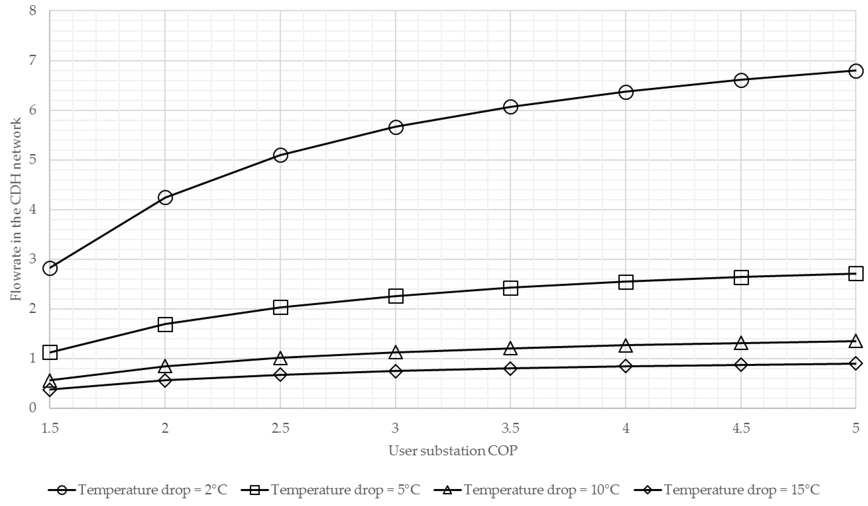
Proper network design in district heating and cooling should generally balance the initial investment and the heat/cold distribution cost. The design is often based on a recommended value for specific pressure loss in the main lines, which is substantially determined by the volumetric flow rate in the network [74,75]. The pipeline diameter of the cold ring is thus determined by total peak flowrate, which is computed in turn on the basis of total peak thermal/cooling demand and available temperature decrease/increase. A comparison can be made between the 3rd district heating network and the proposed CDH network to evaluate under which working conditions CDH thermal carrier flowrate is higher than the traditional system one. The comparison is made taking into consideration a demand of 1 kW th. The traditional district heating network is designed with a 20 °C temperature drop and a thermal loss in the network of about 15% can be estimated as a mean value. A flowrate of about 50.6 L/h is thus needed in the distributing network to deliver 1 kW th to the user. In the case of the CDH network, several parameters have to be taken into account to estimate the water flowrate needed in the cold ring. First of all, depending on the cold water source, different temperature drops may be available. Secondly, the flowrate is also influenced by the COP of the substation heat pump. The COP may vary over a wide range, depending on both the temperature of the cold water in the ring as well as the temperature needed by the user [76], since these parameters respectively influence the evaporator and condenser temperature. Figure 4 shows how the flowrate of CDH varies in comparison with the one required by the traditional district heating network as a function of heat pump COP in the user substation and of available temperature drop in the cold ring (i.e., difference between inlet and outlet cold water temperatures). Thermal losses in a CDH network are negligible. The traditional district heating flowrate of 60.6 L/h computed before is equal to 1 (or 100%) in the y-axis in Figure 4.
Figure 4 shows that a CDH network requires a higher flowrate in comparison with traditional district heating if the allowable temperature drop in the cold ring is under 10 °C: in this case, the pipeline diameter of a CDH network is higher than the diameter of a traditional district heating network. On the other hand, if the temperature drop is over 15 °C a reduction in the requested flowrate can be observed and so the diameter can be potentially reduced. Nevertheless, it should be considered that a CDH network can simultaneously supply users requiring heat and cold. So, the greater the balance between heat and cold demand, the lower the flowrate required by the cold ring, thus also allowing the use of a water source with more stringent limits on temperature variation. Moreover, heat production can be integrated at substation level, meaning that the energy produced by the cold ring does not have to be equal to the maximum required peak.
4.5. Substation Design
The substations of traditional district heating networks usually include two heat exchangers, one for the production of DHW and one for the production of hot water for heating purposes. An additional heat exchanger for cool water production can be added if the user is also connected to a district cooling network [9,77]. Traditional district heating and cooling substations are therefore compact and do not require large areas for the installation.
A CDH network requires user substations with a higher level of complexity. Larger machines should be installed (multi-purpose heat pumps), including tanks for the storage of hot and/or cold water. Energy back-up and integration units may also be present. As a result, the installation of the substation may need a large area: this can become an important issue, especially in the case of connection of existing buildings to a CDH network.
4.6. Ability to Utilize Renewable Energy and Create a Smart Energy System
A smart energy grid can be defined as an energy system in which smart electricity, thermal and gas grids are combined and coordinated to identify synergies between them to achieve an optimal solution for each individual sector as well as for the overall energy system [78]. Traditional district heating and cooling networks are not suitable for this kind of smart integration, since the relatively high temperature of the water delivered in the network makes the system quite rigid and does not allow easy integration with renewables. Moreover, the energy flux is mono-directional, from the central plant to the users and cannot be reversed.
Conversely, the construction of a CDH network with energy integrated substations can be a way of creating a smart energy system. In fact, the substation (see Figure 3) is open to integration coming from different potential sources. First of all, it is possible to integrate DHW production with solar thermal or hybrid photovoltaic-thermal (PV/T) panels, which are an interesting alternative to produce both electric and thermal energy when limited area for panel installation is available [79]. Depending on the characteristics of each user’s heating terminal (i.e., floor heating or radiators) the hot water delivery temperature may be at different level. So, if relatively low temperatures are required for heating purposes, thermal solar and/or PV/T panels can be considered also for the integration on the heating side. When higher temperatures are required, it may be interesting to evaluate other renewables, like biomass boilers.
A CDH network also gives the user the possibility of returning heat and/or cold to the cold ring: the cold ring thus performs a bidirectional energy exchange between the network and the users. This can be a revolutionary aspect, since up to now the district heating and cooling business model has been defined as an energy sell to customers wherein energy price is the key driver. In a CDH network, the user can create a mutual exchange of energy with the network. In fact, under certain conditions, the network may require heat or cold from users who can deliver energy to the cold ring: for example, in wintertime heat can be sent to the network to reduce the temperature decrease of the cold ring, thus allowing water discharge limits (if any) to be respected. Nevertheless, to be really effective the bidirectional system [80,81] needs a sophisticated smart metering network and an efficient control and regulation system, including novel business models [82,83,84]. Two relevant issues can thus be identified: the first one is the cost of the metering and control infrastructure, while the second one is the reliability of the smart meters.
Finally, a CDH network can create a smart energy system: the presence of both substation thermal storage (hot and cold) and/or widespread thermal storage (i.e., ATES system) and the possibility to integrate the network with energy produced locally by renewables is the first step in creating a smart thermal energy network. Nevertheless, the heat pumps installed in the substation need electric energy: the electric grid is thus also involved in the development of CDH network. The diffusion of small size electric energy consumers that can be remotely controlled can lead to the implementation of an effective integrated community energy system [85]. The creation of electrically driven substation can thus be a way to connect a thermal grid with the electric grid. The multi-purpose heat pump can consume electric energy when the energy is produced at lower costs, or when peak production coming from renewable plants is present, thus also favouring electric grid conservation [86,87] and it can produce heat or cold to be stored and consumed later by the users or by the network (cold ring). A methane grid can also be included in the network [88,89], since a methane boiler can be installed as a back-up or integration unit of the multi-purpose heat pump, especially in substations connected to users requiring hot water at high temperatures (i.e., over 65 °C). In this case too, the presence of thermal storage can allow the real-time use of the cheapest form of energy.
5. Conclusions
The purpose of the paper was to define the concept of cold district heating (CDH), including the description of which water source can be used for the application and how the network as well as the substation should be set up. The paper described the state of the art of existing examples of CDH. Finally, the paper identified drawbacks and benefits of CDH networks in comparison with traditional district heating and cooling networks, thus identifying the future challenges that a CDH network has to meet to reach full implementation. Further investigations are needed to identify in which working and environmental conditions the CDH network can be a reliable and sustainable alternative to current district heating and cooling network applications.
Acknowledgments
The authors acknowledge the Climate KIC Association and the European Institute of Innovation and Technology, that financed the research activities.
Conflicts of Interest
The authors declare no conflicts of interest.
References
- Østergaard, P.A.; Mathiesen, B.V.; Möller, B.; Lund, H. A renewable energy scenario for Aalborg municipality based on low-temperature geothermal heat, wind power and biomass. Energy 2010, 35, 4892–4901. [Google Scholar] [CrossRef]
- Lund, H. Renewable energy strategies for sustainable development. Energy 2007, 32, 912–919. [Google Scholar] [CrossRef]
- Amiri, S.; Weinberger, G. Increased cogeneration of renewable electricity through energy cooperation in a Swedish district heating system—A case study. Renew. Energy 2018, 116, 866–877. [Google Scholar] [CrossRef]
- Olsthoorn, D.; Haghighat, F.; Mirzaei, P.A. Integration of storage and renewable energy into district heating systems: A review of modelling and optimization. Sol. Energy 2016, 136, 49–64. [Google Scholar] [CrossRef]
- Wang, D.; Orehounig, K.; Carmeliet, J. Investigating the potential for district heating networks with locally integrated solar thermal energy supply. Energy Proc. 2017, 122, 1057–1062. [Google Scholar] [CrossRef]
- Sepponen, M.; Heimonen, I. Business concepts for districts’ Energy hub systems with maximised share of renewable energy. Energy Build. 2016, 124, 273–280. [Google Scholar] [CrossRef]
- Collins, J.F. The history of district heating. Dist. Heat. 1976, 62, 154–161. [Google Scholar]
- Vesterlund, M.; Toffolo, A. Design Optimization of a District Heating Network Expansion, a Case Study for the Town of Kiruna. Appl. Sci. 2017, 7, 488. [Google Scholar] [CrossRef]
- Werner, S. International review of district heating and cooling. Energy 2017, 137, 617–631. [Google Scholar] [CrossRef]
- Danielewicz, J.; Śniechowska, B.; Sayegh, M.A.; Fidorów, N.; Jouhara, H. Three-dimensional numerical model of heat losses from district heating network pre-insulated pipes buried in the ground. Energy 2016, 108, 172–184. [Google Scholar] [CrossRef]
- Comakli, K.; Yuksel, B.; Comakli, O. Evaluation of energy and exergy losses in district heating network. Appl. Therm. Eng. 2004, 24, 1009–1017. [Google Scholar] [CrossRef]
- Kecebas, A.; Alkan, M.A.; Bayhan, M. Thermo-economic analysis of pipe insulation for district heating piping systems. Appl. Therm. Eng. 2011, 31, 3929–3937. [Google Scholar] [CrossRef]
- Nussbaumer, T.; Thalmann, S. Influence of system design on heat distribution costs in district heating. Energy 2016, 101, 496–505. [Google Scholar] [CrossRef]
- Tereshchenko, T.; Nord, N. Importance of Increased Knowledge on Reliability of District Heating Pipes. Proc. Eng. 2016, 146, 415–423. [Google Scholar] [CrossRef] [Green Version]
- Winterscheid, C.; Holler, S.; Dalenback, J.O. Integration of solar thermal systems into existing district heating systems. Energy Proc. 2017, 116, 158–169. [Google Scholar] [CrossRef]
- Ion, I.V.; Popescu, F.; Dimofte, E. Integration of biomass resources into existent district heating system. In Proceedings of the 6th International Conference on Thermal Equipment, Renewable Energy and Rural Development, Moieciu de Sus, Romania, 8–10 June 2017. [Google Scholar]
- Christenson, M.; Manz, H.; Gyalistras, D. Climate warming impact on degree-days and building energy demand in Switzerland. Energy Convers. Manag. 2006, 47, 671–686. [Google Scholar] [CrossRef]
- Wang, H.; Chen, Q. Impact of Climate Change Heating and Cooling Energy Use in Buildings in the United States. Energy Build. 2014, 82, 428–436. [Google Scholar] [CrossRef]
- Worm, J.; Jorgensen, H.; Thorsen, J.E.; Bennetsen, J.; Ting Larsen, C.; Juhl, O.; Lang, S.; Rosenberg, F.; Kaarup Olsen, P.; Lambertsen, H.; et al. Udvikling og Demonstration af Lavenergifjernvarme til Lavenergibyggeri (Development and Demonstration of Low-Energy District Heating for Low-Energy Housing); Teknologisk Institut: Taastrup, Denmark, 2011. [Google Scholar]
- Østergaard, D.; Svendsen, S. Space heating with ultra-low-temperature district heating—A case study of four single-family houses from the 1980s. Energy Proc. 2017, 116, 226–235. [Google Scholar] [CrossRef]
- Yang, X.; Li, H.; Svendsen, S. Evaluations of different domestic hot water preparing methods with ultra-low-temperature district heating. Energy 2016, 109, 248–259. [Google Scholar] [CrossRef]
- Lund, H.; Werner, S.; Wiltshire, R.; Svendsen, S.; Thorsen, J.E.; Hvelplund, F.; Mathisen, B.V. 4th Generation District Heating (4GDH) Integrating smart thermal grids into future sustainable energy systems. Energy 2014, 68, 1–11. [Google Scholar] [CrossRef]
- Paiho, S.; Reda, F. Towards next generation district heating in Finland. Renew. Sustain. Energy Rev. 2016, 65, 915–924. [Google Scholar] [CrossRef]
- Li, H.; Wang, S.J. Challenges in Smart Low-Temperature District Heating Development. Energy Proc. 2014, 61, 1472–1475. [Google Scholar] [CrossRef] [Green Version]
- Tunzi, M.; Ostergaard, D.S.; Svendsen, S.; Boukhanouf, R.; Cooper, E. Method to investigate and plan the application of low temperature district heating to existing hydraulic radiator systems in existing buildings. Energy 2016, 113, 413–421. [Google Scholar] [CrossRef]
- Li, H.; Svendsen, S. Energy and exergy analysis of low temperature district heating network. Energy 2012, 45, 237–246. [Google Scholar] [CrossRef]
- Brand, M.; Thorsen, J.E.; Svendsen, S. Numerical modelling and experimental measurements for a low-temperature district heating substation for instantaneous preparation of DHW with respect to service pipes. Energy 2012, 41, 392–400. [Google Scholar] [CrossRef]
- Cirule, D.; Pakere, I.; Blumberga, D. Legislative framework for sustainable development of 4th generation district heating system. Energy Proc. 2016, 95, 344–350. [Google Scholar] [CrossRef]
- Ziemele, J.; Gravelsins, A.; Blumberga, A.; Vigants, G.; Blumberga, D. System dynamics model analysis of pathway to 4th generation district heating in Latvia. Energy 2016, 110, 85–94. [Google Scholar] [CrossRef]
- Ziemele, J.; Gravelsins, A.; Blumberga, A.; Blumberga, D. Combining energy efficiency at source and at consumer to reach 4th generation district heating: Economic and system dynamics analysis. Energy 2017, 137, 595–606. [Google Scholar] [CrossRef]
- Castro Flores, J.F.; Lacarriere, B.; Chiu, J.N.W.; Martin, V. Assessing the techno-economic impact of low-temperature subnets in conventional district heating networks. Energy Proc. 2017, 116, 260–272. [Google Scholar] [CrossRef]
- Kofinger, M.; Basciotti, D.; Schmidt, R.R.; Meissner, E.; Doczekal, C.; Giovannini, A. Low temperature district heating in Austria: Energetic, ecologic and economic comparison of four case studies. Energy 2016, 110, 95–104. [Google Scholar] [CrossRef]
- Baldvinsson, I.; Nakata, T. A feasibility and performance assessment of a low temperature district heating system—A North Japanese case study. Energy 2016, 95, 155–174. [Google Scholar] [CrossRef]
- Schmidt, D.; Kallert, A.; Blesl, M.; Svendsen, S.; Li, H.; Nord, N.; Sipila, K. Low temperature district heating for future energy systems. Energy Proc. 2017, 116, 26–38. [Google Scholar] [CrossRef]
- Brand, M.; Svendsen, S. Renewable-based low-temperature district heating for existing buildings in various stages of refurbishment. Energy 2013, 62, 311–319. [Google Scholar] [CrossRef]
- Nord, N.; Ingebretsen, M.E.; Tryggestad, I.S. Possibilities for Transition of Existing Residential Buildings to Low Temperature District Heating System in Norway. In Proceedings of the 12th REHVA World Congress, Aalborg, Denmark, 22–25 May 2016. [Google Scholar]
- Bunning, F.; Wetter, M.; Fuchs, M.; Muller, D. Bidirectional low temperature district energy systems with agent-based control: Performance comparison and operation optimization. Appl. Energy 2018, 209, 502–515. [Google Scholar] [CrossRef]
- Yang, X.; Li, H.; Svendsen, S. Decentralized substations for low-temperature district heating with no Legionella risk, and low return temperatures. Energy 2016, 110, 65–74. [Google Scholar] [CrossRef]
- Palm, J.; Gustafsson, S. Barriers to and enablers of district cooling expansion in Sweden. J. Clean. Prod. 2018, 172, 39–45. [Google Scholar] [CrossRef]
- Gang, W.; Wang, S.; Xiao, F.; Gao, D. District cooling systems: Technology integration, system optimization, challenges and opportunities for applications. Renew. Sustain. Energy Rev. 2016, 53, 253–264. [Google Scholar] [CrossRef]
- Adnot, J. Energy Efficiency and Certification of Central Air Conditioners (EECCAC); Technical Report; Armines: Paris, France, 2003. [Google Scholar]
- Spinoni, J.; Vogt, J.; Barbosa, P. European degree-day climatologies and trends for the period 1951–2011. Int. J. Climatol. 2015, 35, 25–36. [Google Scholar] [CrossRef]
- Conte, B.; Bruno, J.C.; Coronas, A. Optimal Cooling Load Sharing Strategies for Different Types of Absorption Chillers in Trigeneration Plants. Energies 2016, 9, 573. [Google Scholar] [CrossRef]
- Arabkoohsar, A.; Andresen, G.B. Supporting district heating and cooling networks with a bifunctional solar assisted absorption chiller. Energy Convers. Manag. 2017, 148, 184–196. [Google Scholar] [CrossRef]
- Liu, M.; Shi, Y.; Fang, F. Combined cooling, heating and power systems: A survey. Renew. Sustain. Energy Rev. 2014, 35, 1–22. [Google Scholar] [CrossRef]
- Yu, Q.D. Theory of energy level and its application in water-loop heat pump system. Appl. Therm. Eng. 2017, 119, 269–274. [Google Scholar] [CrossRef]
- Polzot, A.; Dipasquale, C.; D’Agaro, P.; Cortella, G. Energy benefit assessment of a water loop heat pump system integrated with a CO2 commercial refrigeration unit. Energy Proc. 2017, 123, 36–45. [Google Scholar] [CrossRef]
- Lee, K.S. A Review on Concepts, Applications, and Models of Aquifer Thermal Energy Storage Systems. Energies 2010, 3, 1320–1334. [Google Scholar] [CrossRef]
- Bloemendal, M.; Olsthoorn, T.; Boons, F. How to achieve optimal and sustainable use of the subsurface for Aquifer Thermal Energy Storage. Energy Policy 2014, 66, 104–114. [Google Scholar] [CrossRef]
- Buyukalaca, O.; Ekinci, F.; Yilmaz, T. Experimental investigation of Seyhan River and dam lake as heat source–sink for a heat pump. Energy 2003, 28, 157–169. [Google Scholar] [CrossRef]
- Liu, Z.; Tan, H.; Li, Z. Heating and Cooling Performances of River-Water Source Heat Pump System for Energy Station in Shanghai. Proc. Eng. 2017, 205, 4074–4081. [Google Scholar] [CrossRef]
- Song, Y.; Akashi, Y.; Yee, J.J. Effects of utilizing seawater as a cooling source system in a commercial complex. Energy Build. 2007, 39, 1080–1087. [Google Scholar] [CrossRef]
- Elías-Maxil, J.A.; van der Hoek, J.P.; Hofman, J.; Rietveld, L. Energy in the urban water cycle: Actions to reduce the total expenditure of fossil fuels with emphasis on heat reclamation from urban water. Renew. Sustain. Energy Rev. 2014, 30, 808–820. [Google Scholar] [CrossRef] [Green Version]
- Fiore, S.; Genon, G. Heat recovery from municipal wastewater: Evaluation and proposals. Environ. Eng. Manag. J. 2014, 13, 1595–1604. [Google Scholar]
- Kahraman, A.; Celebi, A. Investigation of the Performance of a Heat Pump Using Waste Water as a Heat Source. Energies 2009, 2, 697–713. [Google Scholar] [CrossRef]
- De Pasquale, A.M.; Giostri, A.; Romano, M.C.; Chiesa, P.; Demeco, T.; Tani, S. District heating by drinking water heat pump: Modelling and energy analysis of a case study in the city of Milan. Energy 2017, 118, 246–263. [Google Scholar] [CrossRef]
- Manfren, M.; Caputo, P.; Costa, G. Paradigm shift in urban energy systems through distributed generation: Methods and models. Appl. Energy 2011, 88, 1032–1048. [Google Scholar] [CrossRef]
- Gadd, H.; Werner, S. Heat load patterns in district heating substations. Appl. Energy 2013, 108, 176–183. [Google Scholar] [CrossRef]
- Zabasta, A.; Selmanovs-Pless, V.; Kunicina, N.; Ribickis, L. Wireless Sensor Networks for Optimisation of District Heating. J. Energy Power Eng. 2013, 7, 1362–1369. [Google Scholar]
- Liu, L.; Fu, L.; Jiang, Y. A new “wireless on-off control” technique for adjusting and metering household heat in district heating system. Appl. Therm. Eng. 2012, 36, 202–209. [Google Scholar] [CrossRef]
- Xue, P.; Zhou, Z.; Fang, X.; Chen, X.; Liu, L.; Liu, Y.; Liu, J. Fault detection and operation optimization in district heating substations based on data mining techniques. Appl. Energy 2018, 144, 20–30. [Google Scholar] [CrossRef]
- Ma, Z.; Xie, J.; Li, H.; Sun, Q.; Si, Z.; Zhang, J.; Guo, J. The Role of Data Analysis in the Development of Intelligent Energy Networks. IEEE Netw. 2017, 31, 88–95. [Google Scholar] [CrossRef]
- Razmara, M.; Bharati, G.R.; Shahbakhti, M.; Paudyal, S.; Robinett, R.D. Bidirectional optimal operation of smart building-to-grid systems. Am. Control Conf. 2015, 288–293. [Google Scholar] [CrossRef]
- Rybach, L.; Wilhelm, J.; Gorhan, H. Geothermal use of tunnel waters—A Swiss speciality. In Proceedings of the International Geothermal Conference, Reykjavík, Iceland, 14–17 September 2003. [Google Scholar]
- Pietruschka, D.; Brennenstuhl, M.; Matthiss, B.; Binder, J. Decentralised heat pumps and small electricity storages as active components in a virtual power plant for smart grid services. In Proceedings of the 15th International Conference on Environment and Electrical Engineering (EEEIC), Rome, Italy, 10–13 June 2015. [Google Scholar]
- Sanner, B. Market and potential for geothermal energy in Europe. In Proceedings of the GeoEnergi 2015, Bergen, Norway, 2–3 September 2015. [Google Scholar]
- Stubler, A.; Bestenlehner, D.; Druck, H. Energy saving potentials of cold district heating networks. In Proceedings of the 17th EWA Symposium during IFAT 2014, München, Germany, 6–7 May 2014. [Google Scholar]
- Molinari, F.C.; Tarantino, P. New Projects for Geothermal District Heating and Cooling Systems in the Brescia Province-Northern Italy. In Proceedings of the Workshop on Geothermal Energy Status and Future in the Peri–Adriatic Area, Veli Lošinj, Croatia, 25–27 August 2014. [Google Scholar]
- Bianchini, A.; Pellegrini, M.; Saccani, C. Wide use of sustainable energy from aquifers in Italy: Pilot plant design and implementation. In Proceedings of the 22nd Summer School Francesco Turco, Palermo, Italy, 13–15 September 2017. [Google Scholar]
- Chmutina, K.; Goodier, C.I. Case Study Analysis of Urban Decentralised Energy Systems. In Climate-Smart Technologies; Leal Filho, W., Mannke, F., Mohee, R., Schulte, V., Surroop, D., Eds.; Springer: Berlin/Heidelberg, Germany, 2013; ISBN 978-3-642-37752-5. [Google Scholar]
- Brielmann, H.; Griebler, C.; Schmidt, S.I.; Michel, R.; Lueders, T. Effects of thermal energy discharge on shallow groundwater ecosystems. FEMS Microbiol. Ecol. 2009, 68, 273–286. [Google Scholar] [CrossRef] [PubMed]
- Madden, N.; Lewis, A.; Davis, M. Thermal effluent from the power sector: An analysis of once-through cooling system impacts on surface water temperature. Environ. Res. Lett. 2013, 8, 1–8. [Google Scholar] [CrossRef]
- Ni, Z.; van Gaans, P.; Smit, M.; Rijnaarts, H.; Grotenhuis, T. Combination of aquifer thermal energy storage and enhanced bioremediation: Resilience of reductive dechlorination to redox changes. Appl. Microbiol. Biotechnol. 2015, 100, 3767–3780. [Google Scholar] [CrossRef] [PubMed]
- Wang, H.; Duanmu, L.; Li, X.; Lahdelma, R. Optimizing the District Heating Primary Network from the Perspective of Economic-Specific Pressure Loss. Energies 2017, 10, 1095. [Google Scholar] [CrossRef]
- Yildirim, N.; Toksoy, M.; Gokcen, G. Piping network design of geothermal district heating systems: Case study for a university campus. Energy 2010, 35, 3256–3262. [Google Scholar] [CrossRef]
- Nord, N.; Schmidt, D.; Dagmar Kallert, A.M. Necessary measures to include more distributed renewable energy sources into district heating systems. Energy Proc. 2017, 116, 48–57. [Google Scholar] [CrossRef]
- Werner, S. District heating and cooling in Sweden. Energy 2017, 126, 419–429. [Google Scholar] [CrossRef]
- Lund, H. Renewable Energy Systems: A Smart Energy Systems Approach to the Choice and Modelling of 100% Renewable Solutions, 2nd ed.; Academic Press: Burlington, ON, Canada, 2014; ISBN 978-0-12-410423-5. [Google Scholar]
- Bianchini, A.; Guzzini, A.; Pellegrini, M.; Saccani, C. Photovoltaic/thermal (PV/T) solar system: Experimental measurements, performance analysis and economic assessment. Renew. Energy 2017, 111, 543–555. [Google Scholar] [CrossRef]
- Hassine, I.B.; Eicker, U. Control aspects of decentralized solar thermal integration into district heating networks. Energy Proc. 2014, 48, 1055–1064. [Google Scholar] [CrossRef]
- Ancona, M.A.; Branchini, L.; De Pascale, A.; Melino, F. Smart district heating: Distributed generation systems’ effects on the network. Energy Proc. 2015, 75, 1208–1213. [Google Scholar] [CrossRef]
- Hwang, J.; Choi, M.; Lee, T.; Jeon, S.; Kim, S.; Park, S.; Park, S. Energy Prosumer Business Model Using Blockchain System to Ensure Transparency and Safety. Energy Proc. 2017, 141, 194–198. [Google Scholar] [CrossRef]
- Mengelkamp, E.; Garttner, J.; Rock, K.; Kessler, S.; Orsini, L.; Weinhardt, C. Designing microgrid energy markets: A case study: The Brooklyn Microgrid. Appl. Energy 2018, 210, 870–880. [Google Scholar] [CrossRef]
- Reynolds, J.; Rezgui, Y.; Hippolyte, J. Upscaling energy control from building to districts: Current limitations and future perspectives. Sustain. Cities Soc. 2017, 35, 816–829. [Google Scholar] [CrossRef]
- Koirala, B.P.; Chaves Ávila, J.P.; Gómez, T.; Hakvoort, R.A.; Herder, P.M. Local Alternative for Energy Supply: Performance Assessment of Integrated Community Energy Systems. Energies 2016, 9, 981. [Google Scholar] [CrossRef]
- Goop, J.; Odenberger, M.; Johnsson, F. The effect of high levels of solar generation on congestion in the European electricity transmission grid. Appl. Energy 2017, 205, 1128–1140. [Google Scholar] [CrossRef]
- Zhang, G.; Cao, Y.; Cao, Y.; Li, D.; Wang, L. Optimal Energy Management for Microgrids with Combined Heat and Power (CHP) Generation, Energy Storages, and Renewable Energy Sources. Energies 2017, 10, 1288. [Google Scholar] [CrossRef]
- Wu, Q.H.; Zheng, J.; Jing, Z. Coordinated Scheduling of Energy Resources for Distributed DHCs in an Integrated Energy Grid. J. Power Energy Sources 2015, 1, 95–103. [Google Scholar] [CrossRef]
- Badami, M.; Fonti, A.; Carpignano, A.; Grosso, D. Design of district heating networks through an integrated thermo-fluid dynamics and reliability modelling approach. Energy 2018, 144, 826–838. [Google Scholar] [CrossRef]
Figure 1.
Cold district heating and cooling network. The scheme includes the primary-secondary circuit option, as well as the possibility to pre-heat the water flowing through the cold ring.
Figure 1.
Cold district heating and cooling network. The scheme includes the primary-secondary circuit option, as well as the possibility to pre-heat the water flowing through the cold ring.
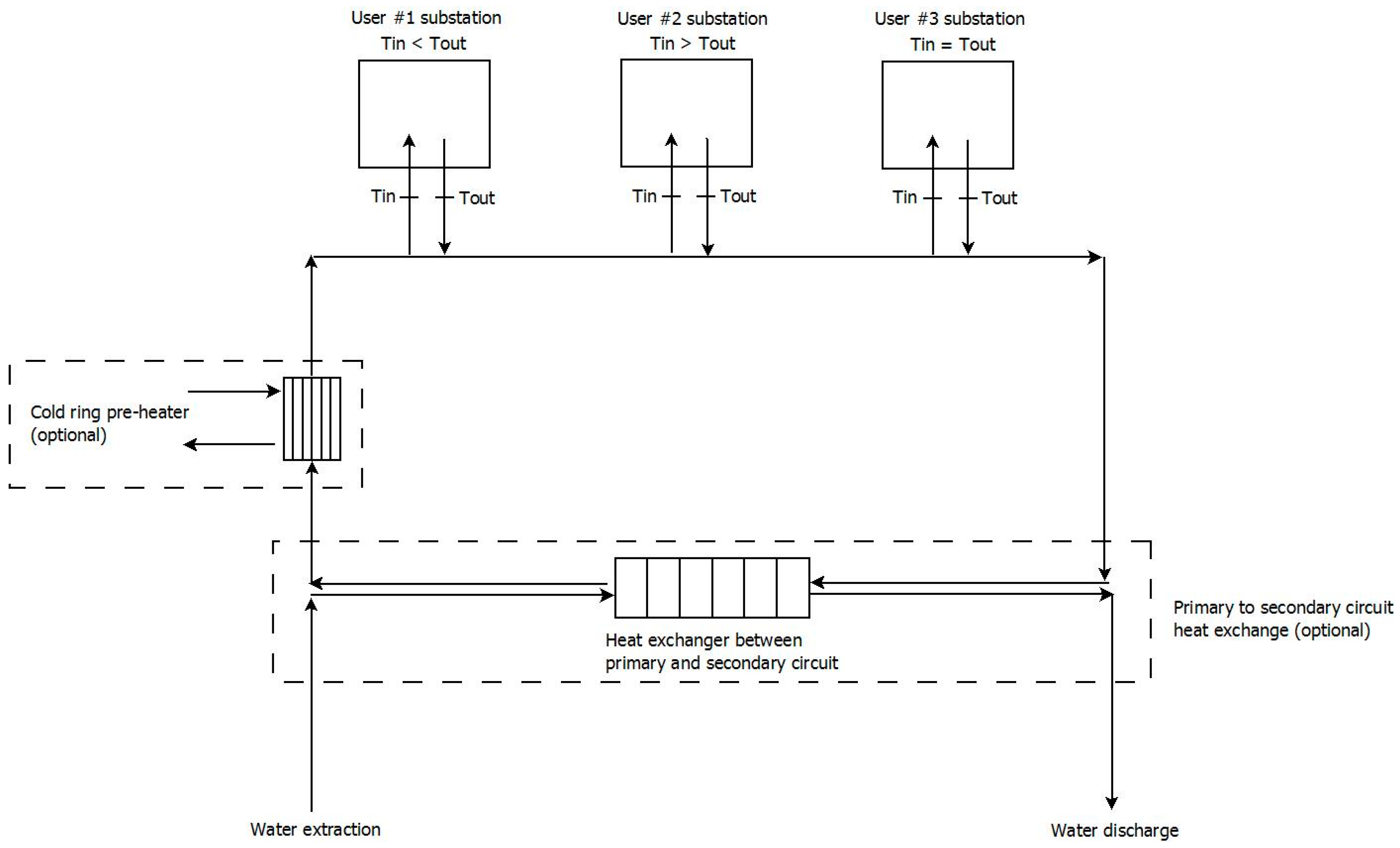
Figure 2.
Piping and Instrumentation Diagram (P&ID) of a multi-purpose heat pump system: in particular, heat exchangers (S1, S2, S3), solenoid valves (V1, V2, V3, V4, V5), expansion valves (EV1, EV2) and non-return valves (NRV) are shown.
Figure 2.
Piping and Instrumentation Diagram (P&ID) of a multi-purpose heat pump system: in particular, heat exchangers (S1, S2, S3), solenoid valves (V1, V2, V3, V4, V5), expansion valves (EV1, EV2) and non-return valves (NRV) are shown.
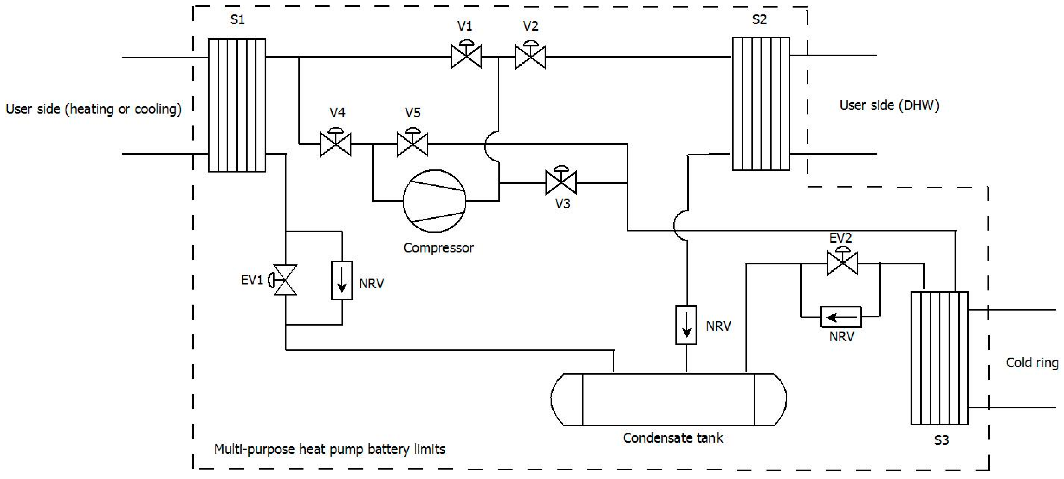
Figure 3.
P&ID of an example of a substation for a cold district heating (CDH) network. DHW: domestic hot water.
Figure 3.
P&ID of an example of a substation for a cold district heating (CDH) network. DHW: domestic hot water.

Figure 4.
Flowrate network comparison between traditional district heating (equal to 1) and CDH as a function of available temperature drop in the CDH network and of heat pump coefficient of performance (COP) of the user substation.
Figure 4.
Flowrate network comparison between traditional district heating (equal to 1) and CDH as a function of available temperature drop in the CDH network and of heat pump coefficient of performance (COP) of the user substation.
© 2018 by the authors. Licensee MDPI, Basel, Switzerland. This article is an open access article distributed under the terms and conditions of the Creative Commons Attribution (CC BY) license (http://creativecommons.org/licenses/by/4.0/).
Share and Cite
MDPI and ACS Style
Pellegrini, M.; Bianchini, A. The Innovative Concept of Cold District Heating Networks: A Literature Review. Energies 2018, 11, 236. https://doi.org/10.3390/en11010236
AMA Style
Pellegrini M, Bianchini A. The Innovative Concept of Cold District Heating Networks: A Literature Review. Energies. 2018; 11(1):236. https://doi.org/10.3390/en11010236
Chicago/Turabian StylePellegrini, Marco, and Augusto Bianchini. 2018. "The Innovative Concept of Cold District Heating Networks: A Literature Review" Energies 11, no. 1: 236. https://doi.org/10.3390/en11010236
Note that from the first issue of 2016, this journal uses article numbers instead of page numbers. See further details here.