Sensorless Speed Control Based on the Improved Q-MRAS Method for Induction Motor Drives

Power Electronics and Electrical Drives Center, Harbin Institute of Technology (Shenzhen), Shenzhen 518055, China
*
Author to whom correspondence should be addressed.
Energies 2018, 11(1), 235; https://doi.org/10.3390/en11010235
Submission received: 20 December 2017
/
Revised: 9 January 2018
/
Accepted: 11 January 2018
/
Published: 19 January 2018
Abstract
:For high-power and high-performance speed control system, speed feedback signals are generally required. The employment of sensorless control technology makes the installation of the system easier and lower-cost, while its reliability needs to be improved. The robustness of the improved instantaneous reactive power based on the quadrature model reference adaptive system (MRAS) with respect to the variation of the motor inductance parameter is improved by selecting the appropriate reference model and adjustable model. The improved instantaneous reactive power (Q) based on model reference adaptive system (Q-MRAS) algorithm is studied by small signal analysis, and the stability of the control system is verified by the Routh Stability Criterion. The simulation models and experimental platform for the proposed control are built in the laboratory. The feasibility and superiority are verified by the corresponding simulation and experimental results.
1. Introduction
The regulation system for the high equality induction motor speed applications are guaranteed by the precious speed closed-loop control. If the speed encoder, rotary transformer, or other speed measuring device are used to obtain the speed signal, the difficulty of installation and the related cost will be problematic. Additionally, the reliability of the speed sensor will be decreased in harsh environments. Sensorless speed control technology has been introduced to estimate the real-time speed without the assistance of hardware devices. A series of problems brought by the speed sensor can be avoided. Therefore, dozens of sensorless speed estimation methods have been studied and applied [1,2]. Many practical issues need to be considered in the actual application process. Firstly, sensorless speed estimation could be severely affected by the variations of parameters [3,4]. Meanwhile, the accuracy of the speed estimation at low speed and the stability through the full speed range are critical issues of concern [5,6,7]. Therefore, it has been a challenging task to find an appropriate speed estimation method to obtain a satisfactory result in actual engineering applications [8,9,10].
Speed estimation based on the quadrature model reference adaptive system (MRAS) has gained high popularity [11] in sensorless speed control research because of its simple control and superior performance, which was first introduced by Schauer [12]. The flux linkages of the voltage model without a speed variable was used as the reference model of (MRAS), while the flux linkage of the current model including speed was used as the adjustable model. The estimation accuracy and anti-interference performance have been greatly improved compared with the conventional method. It can also ensure the stability of the system. However, there also exist disadvantages for the MRAS method. Since the MRAS method is based on the voltage model and flux linkage, the precision influences the accuracy of the speed estimation, which generally involves parameters related to the stator resistance. This influence could be further deteriorated by the changes in resistance during the motor operation. Meanwhile, the pure integrator contained in the voltage model leads to the accumulation of error and zero drift. This will result in a seriously-affected speed estimation precision for the low-speed operating scenario [13].
To overcome the above-mentioned demerits inherited in the conventional MRAS technique, many research works have been conducted that focus mainly on selecting appropriate reference models and adjustable models. For example, Peng and others proposed a new method by using the back electromotive force (back-EMF) to replace the original flux linkages [14]. In this way, the pure integrator can be avoided. However, stator resistance parameters still exist in the model, which still affects the speed estimation performance in the low speed condition [14]. In [15], the instantaneous air gap reactive power was proposed to replace the back-EMF. The stator resistance parameters are removed from the reference model, which can eliminate its influence over the system speed estimation. However, the reference model still has the derivative operation on stator current. This will cause the MRAS to be extremely sensitive to the noise of the whole system. In addition, other parameters related to the motor, such as the leakage flux coefficient, are also included in the model.
To solve the problems of the speed estimation technique based on air gap reactive power, a new method was proposed in [16,17]. The air gap reactive power was replaced with the reactive power obtained from the induction machine. This method also successfully eliminates the differential term of the stator current. Meanwhile, the whole MRAS system does not have the parameters of stator resistance and the pure integrator, which helps improve the performance of the motor speed estimation significantly. The adjustable model contains motor parameters, such as the flux leakage coefficient, the parameters of inductance, and so on. This may have a negative influence on the rotational speed estimation in the running process of the motor. Additionally, this method also fails to solve the unstable problem of the control system.
In this section, a novel speed estimation scheme based on instantaneous reactive power (Q) based on model reference adaptive system (Q-MRAS) is proposed. In this method, the reactive power in the static coordinate system is used as the reference model, which does not contain information about the rotational speed. However, the reactive power in the rotating coordinate system includes the rotational speed information. The proposed Q-MRAS method does not have motor parameters, which can avoid its influence on the performance of rotating-speed estimation. The limitations of conventional Q-MRAS method and the proposed Q-MRAS method are analyzed in detail. Simulation and the corresponding hardware experiments are conducted to verify the feasibility and superiority of the improved algorithm.
2. The Rotational Speed Estimation Based on the Q-MRAS Method
2.1. The Rotational Speed Estimation Based on Conventional Q-MRAS Method
The mathematical voltage model in synchronous rotation coordinate system (d-q frame) can be expressed as:
where usd, usq, isd, isq, are the stator voltages and currents, respectively; Rs is the stator resistance; Ls, Lr are the inductance of stator and rotor and the Lm is the mutual inductance. ωe is the synchronous speed and ωr is the rotor speed, ωsl is the speed deviation, σ is the magnetic flux leakage factor coefficient.
The instantaneous reactive power of the induction motor can be expressed as:
Combining Equations (1) and (2):
It can be clearly seen in Equation (3) that, compared with the MRAS speed estimation method based on the rotor flux error, the most significant feature in this is that there are no parameters of the stator resistance. Thus, when the motor is operating, the variation of the stator resistance will not have any effects on it. Since there is no pure integrator in this system, it also eliminates the integral drift and other problems. The accuracy of the system will be improved greatly.
Equation (3) is the reactive power when the motor is in transient states. When the motor is in steady states, and Equation (3) is modified to Equation (4). In Equation (4), the differential items all become zero:
Moreover, because ψrd = Lmisd, ψrq = 0, Equation (4) can be simplified to Equation (5):
The structure of conventional Q-MRAS is shown in Figure 1. The reference model of the estimation system is built based on Equation (2), and the adjustable model is shown in Equation (5). The design of adaptive structure is mainly based on the Popov-hyper stability theory. The proportional-integral (PI) regulator is chosen to realize a reliable sensorless speed estimation design.
From Figure 1, it can be found that an error signal processing module is added to the speed estimation system. This module is used to process the reference module and the error signal of reactive power produced by the adjustable model. The speed error signal in the vector control system can be processed in this module as well.
The processing rule is shown in Equation (6). After running through the error signal processing module, the output error is sent to the adaptive structure and, finally, the parameters of rotating speed are regulated in the adjustable module.
Since the whole closed-loop estimation system is strictly positive, the whole system is stable.
where εQ is the reactive power error, and εw is the rotation speed error. d is the output of the module.
2.2. The Rotational Speed Estimation Based on the Improved Q-MRAS Method
The Q-MRAS speed estimation method mentioned above improves the performance of the motor speed estimation, to some extent, compared with the conventional MRAS method. However, there still exist motor parameters that may influence the performance, such as inductance, and so on. To solve the problem of the conventional Q-MRAS algorithm, the reactive power s expressed under the stationary reference frame, are used as the reference model without the rotate speed in this section. The reactive power s under the rotating coordinate system are used as adjustable model, which contains the rotation speed information. By using this method, there are no motor parameters in this MRAS system, which is good for the performance of the system. The basic structure of the proposed improved MRAS can be illustrated in Figure 2.
The reactive power can be expressed as:
In two-phase static coordinates, the reactive power is shown in Equation (8):
The stationary coordinate system of voltage and current are shown in Equation (9):
where Vm, Im are the amplitude of the voltage and the current respectively. ϕ is the phase difference between voltage and current.
Combined the two s above, Equation (10) can be illustrated in the following:
However, the reaction power expression can be shown in Equation (11) under the rotating coordinates.
The voltage and the current under the rotating coordinates can be calculated by the Park transformation in Equation (12):
Combining Equations (11) and (12), Equation (13) is delivered as follows:
The result of Equation (13) is the same as Equation (10), so it is reasonable to build the MRAS system by using this method. Equations (8) and (11) are the reference model and adjustable model, respectively.
In order to ensure that the estimation system can be reliable and correct, the adaptation law design of the improved Q-MRAS system in Figure 2 needs to ensure the stability of the closed-loop system. As a consequence, the self-adaption system can also be designed through Popov’s hyperstability theory.
3. Study on the Stability of the Sensorless Speed Vector Control System
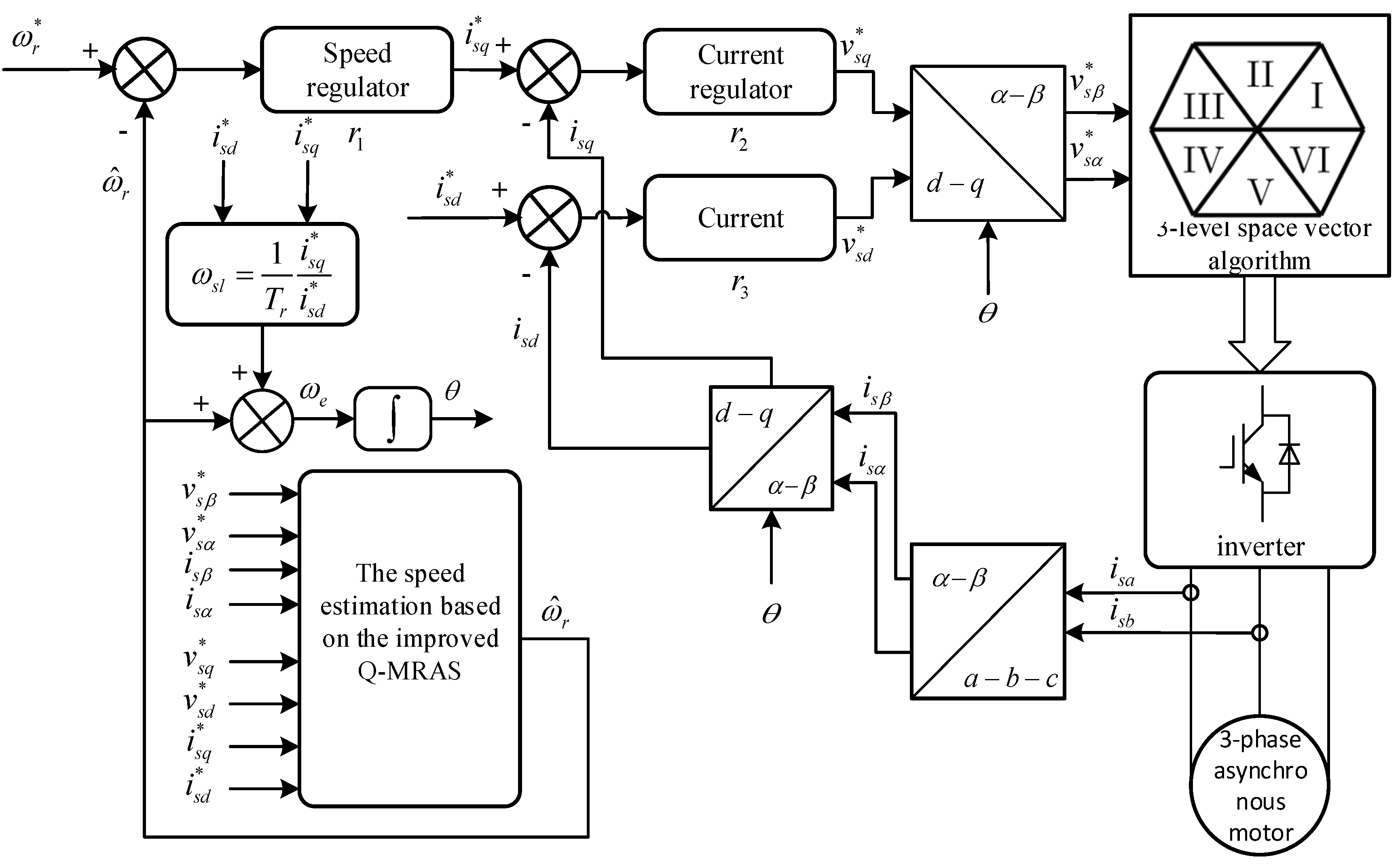
The improved Q-MRAS speed estimation method can be applied in the indirect vector control system of the induction motor to achieve the sensorless speed vector control. The overall design diagram is given in Figure 3.
The speed identification structure, based on the Popov super-stability theory, has ensured the stability of the identification system, as well as the stability of the closed-loop system formed by nonlinear feedback. To improve the dynamic response ability of the system, small signal model is introduced. The state spaces of induction motor are expressed in Equation (14) [17]:
where:
The standard state spaces are written as follows:
Combining Equations (14) and (16):
In Figure 3, the speed regulators and two current regulators in the indirect vector control system employ the common PI controllers, which are shown in the following equations.
Speed regulators:
Current regulators of the q axis:
Current regulators of the d axis:
By using Equations (22) and (23), Equation (19) can be expressed as follows:
The small signal analysis is presented according to the working statement at x0 point in Equation (17):
Equation (25) can be modified to Equation (26) by means of the Laplace transform:
where:
The expressions of (∆isd/∆ωr) and (∆isq/∆ωr) are calculated by substituting A, B, C, ∆A, and ∆u in Equation (26).
The error of the reactive power in the improved Q-MRAS is defined as ε:
Considering a small disturbance ∆ωr produced by the speed:
Equation (33) is obtained by dividing both sides of Equation (32) by ∆ωr.
Meanwhile, according to the structure based on the improved Q-MRAS, it can be expressed in Equation (34):
Combining Equations (33) and (34):
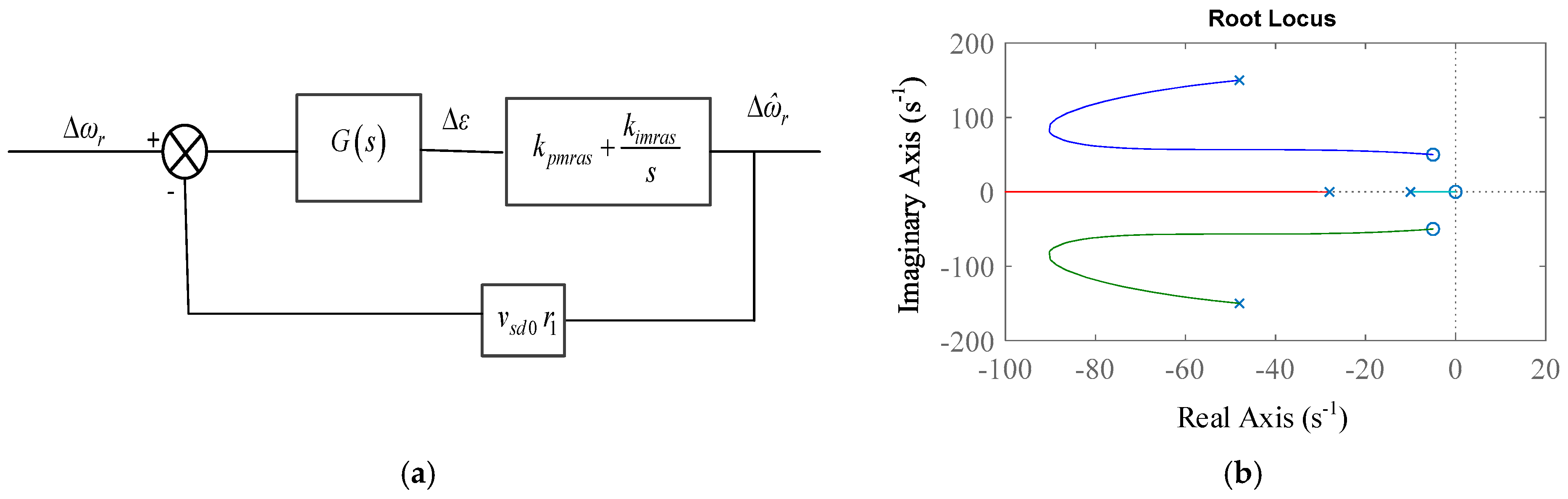
Equation (35) illustrates the transfer function of the variation of input rotation rate and output rotation rate . The block diagram representing the structure of the Q-MRAS based state space is shown in Figure 4a. The root locus plot of Equation (35) for the forward motoring mode is shown in Figure 4b, which represents stability of the speed estimator.
When small disturbances are introduced at the actual speed of the induction motor to guarantee the accurate tracking between the dynamical speed estimation value and the variation of the actual motor speed. The sensorless speed vector control system is stable in Equation (35) mentioned above. The coefficient of the characteristic changes with the specific working condition, and the state of the speed regulating system is determined by the given speed and the load torque. Thus, in the torque-speed area, the whole system’s stability is judged by the Routh Criterion.
In the vector control system simulation platform, the PI parameters of the control system are obtained by integrating the transfer function in Equation (35). The induction motor speed changes from 0 r/min to 1400 r/min, and the load torque changes from 0 Nm to 5 Nm.
The Routh Criterion is utilized to judge the stability of the corresponding system. It can be seen that the indirect vector control system using the improved Q-MRAS speed estimation performs stably when the machine load varies.
4. Simulation Results
According to the Figure 1 and Figure 2, the Q-MRAS simulation model and the improved Q-MRAS simulation model are built according to the Space Vector Pulse Width Modulation (SVPWM) indirect vector control simulation model. Different simulation experiments are set to verify the dynamic performance and the static performance. This model also shows the effect of conventional and improved algorithms through comparative analysis.
4.1. The Rotational Speed Estimation Based on Improved Q-MRAS Method
4.1.1. The Speed Estimation in the Zero-Load Condition
In this test, the induction motor speed is first set to 1400 r/min and the loads are set to 0 Nm. The motor drive is set up at light loads. The results of simulation are shown in Figure 5. In this work, the both the improved algorithm method and the conventional algorithm are able to follow the actual speed value quiet accurately.
The improved Q-MRAS estimation method tracks the actual speed value in the set-up stage of the induction motor. However, this method also has disadvantages, such as containing the delay period and error signals.
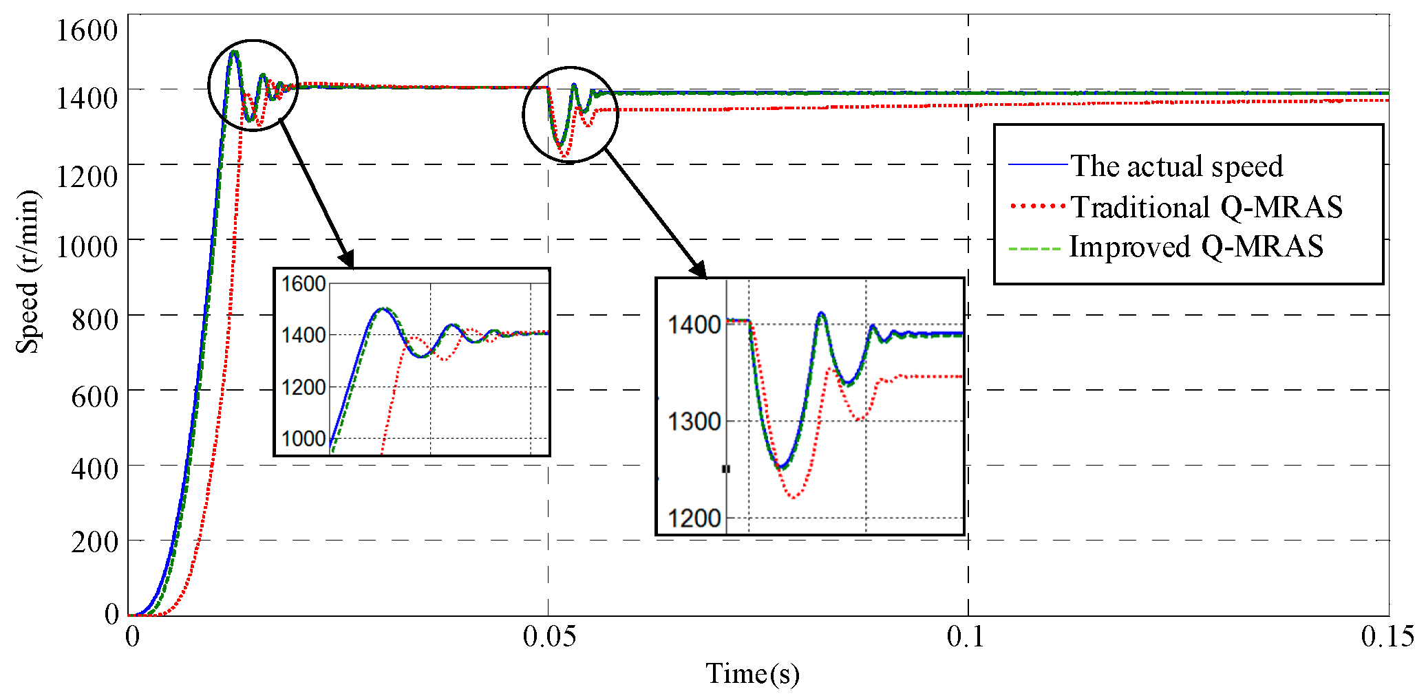
4.1.2. The Speed Estimation from Zero Load to Full Load
In this work, the induction motor speed is set up at 1400 r/min. When the running time is 0.05 s, the load is changed from 0 Nm to 5.11 Nm. Figure 6 shows the simulation result. When the loads change instantly, the improved Q-MRAS algorithm track follows the change of the actual speed of the induction motor, which represents stability of the speed estimator. However, the conventional Q-MRAS estimation algorithm has a greater lag, and the regulation time is very long, so this method has a poor estimation result.
4.1.3. The Speed Estimation in the Condition of Speed Mutation
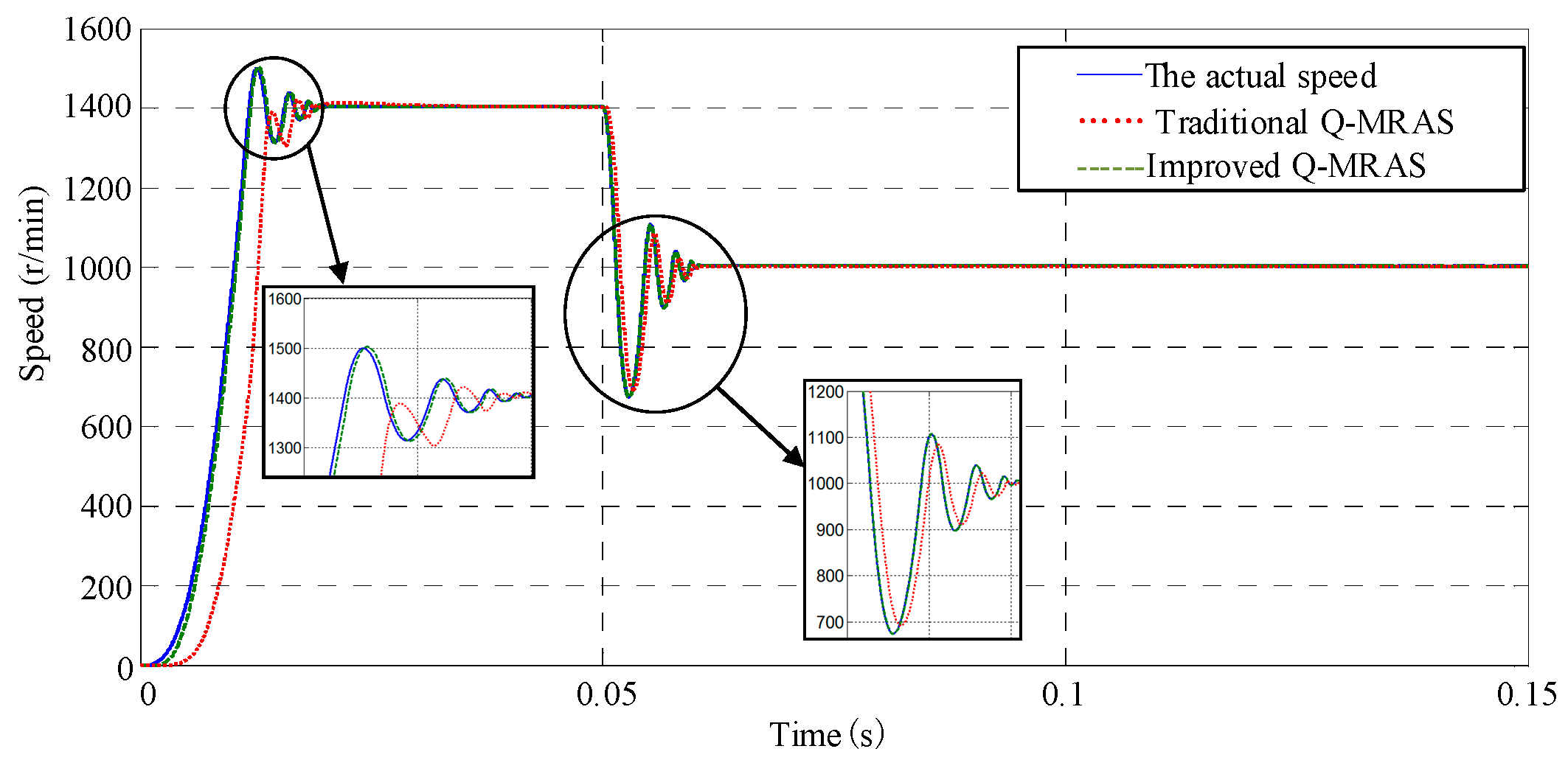
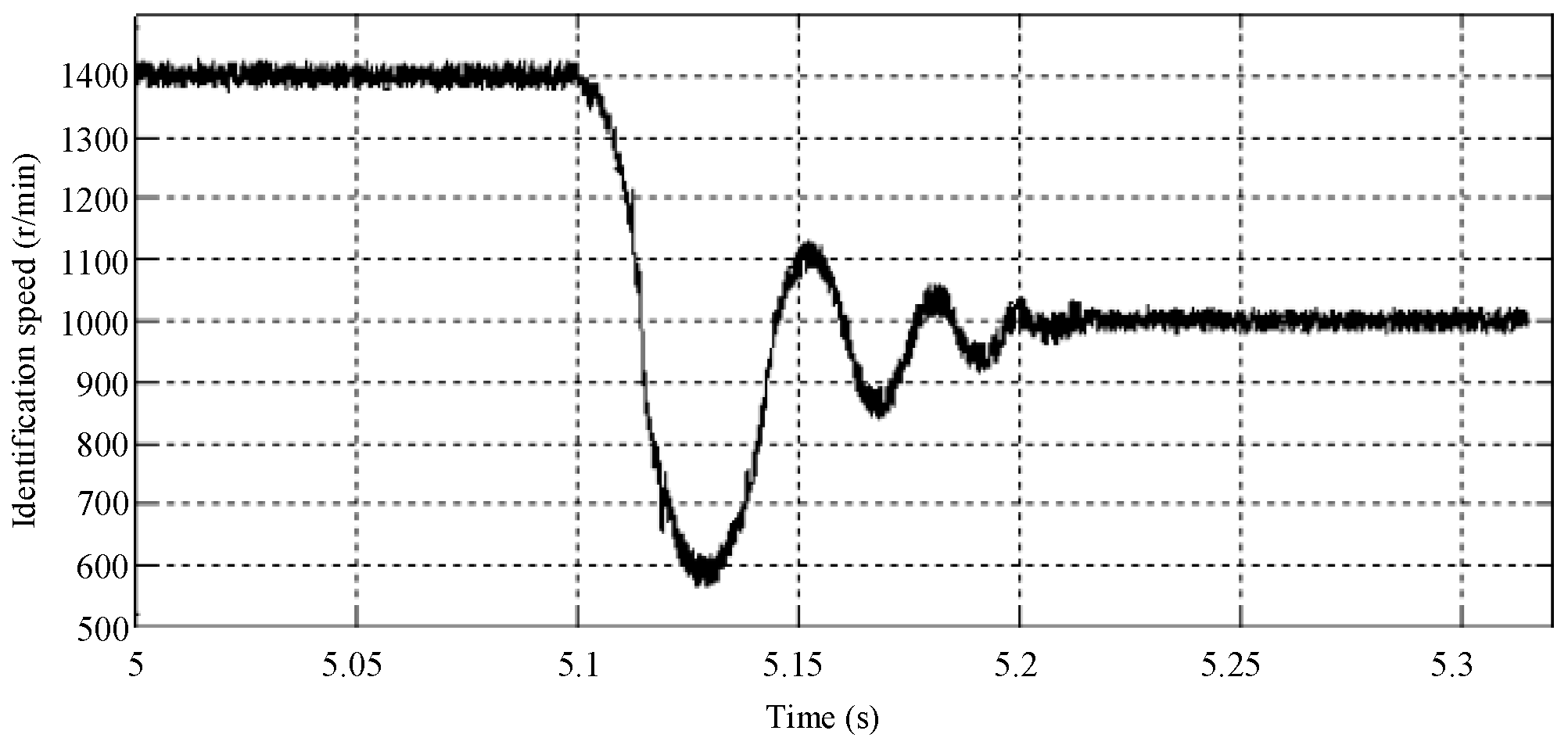
In this work, the induction motor starts in the zero-load condition at a rated speed. When the running time is 0.05 s, the instruction speed changes from 1400 r/min to 1000 r/min instantly. Figure 7 gives the results of simulation. When the motor speed changes instantly, both the improved Q-MRAS algorithm and the conventional estimation method are able to estimate the actual speed well. However, the improved Q-MRAS method has a good tracking performance in the starting process and the mutation process.
4.1.4. The Estimation Result in the Low-Speed Condition
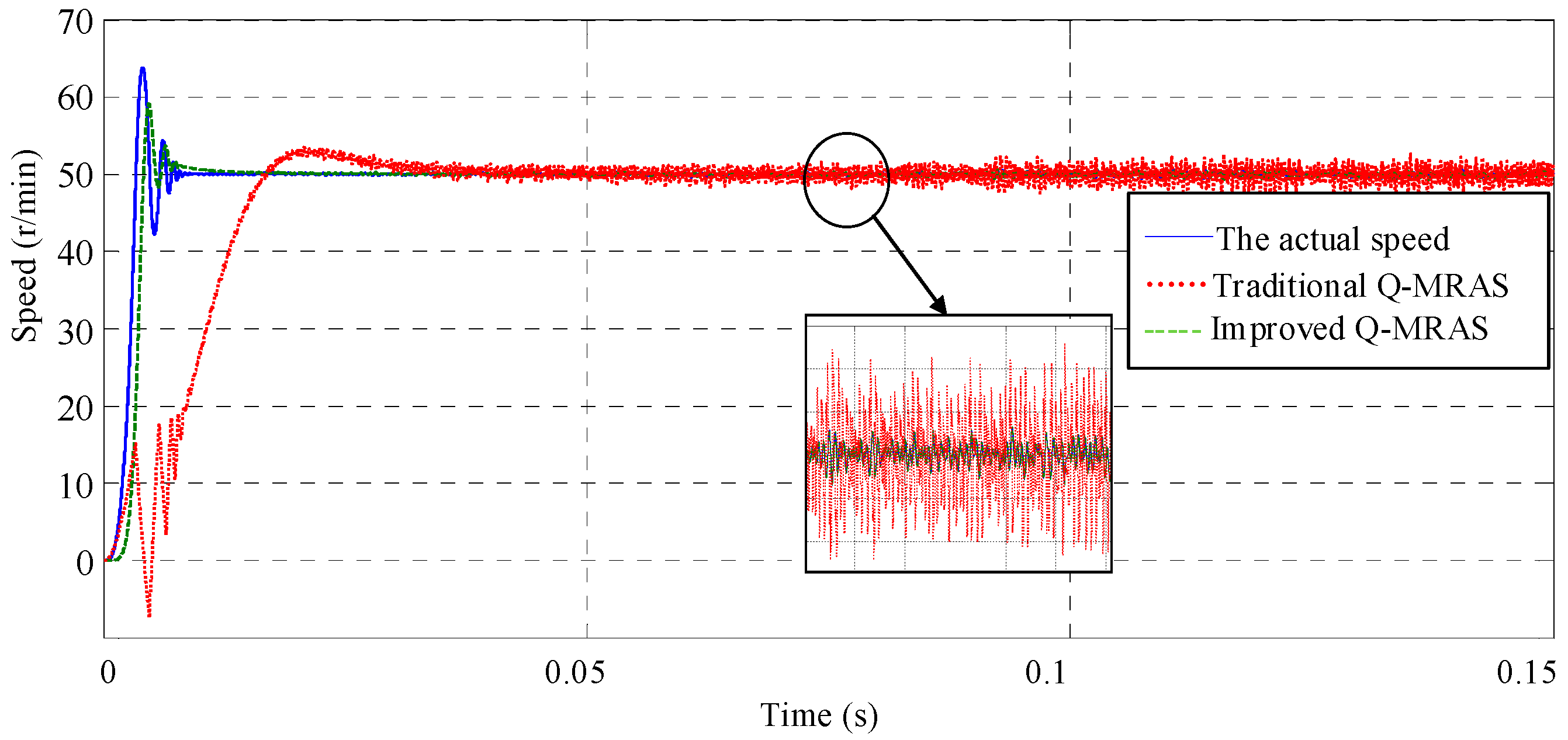
In this work, the motor speed is set to 50 r/min, and the induction motor is set up in the zero load condition. The simulation results are shown in Figure 8.
During the startup process, the results estimated by the Q-MRAS algorithm have a significant difference with the actual speed. The results produced by the improved Q-MRAS algorithm are much better, but the tracking result in the startup process has a slight decline. By observing the enlarged figure of the steady state in Figure 8, the estimation results of Q-MRAS have a high level disturbing, which will have a great influence on the speed estimation accuracy. However, the improved Q-MRAS can also follow the actual speed well in the steady state.
According to all the simulation results above, the improved Q-MRAS algorithm can ensure a high-level accuracy of speed estimation in the speed mutation and low-speed condition compared with the conventional Q-MRAS estimation method. The improved Q-MRAS estimation method also performs well in the dynamic state.
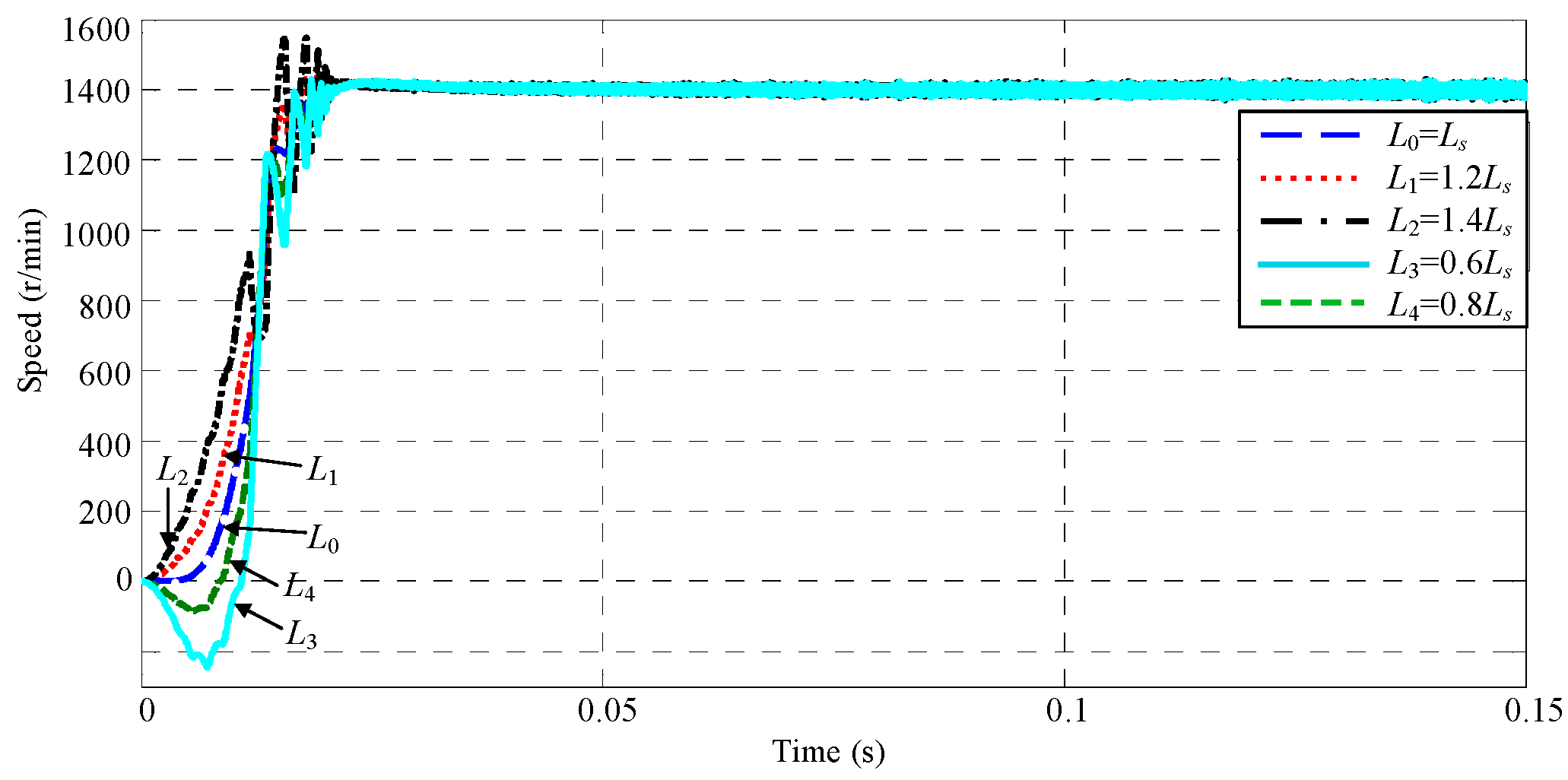
4.2. The Influence on the Speed Estimation by Changing the Inductance Parameter
By observing the improved Q-MRAS estimation method and the Q-MRAS estimation method, the most significant advantage of these two methods is that both of them have no relationship with motor parameters. Thus, it can avoid the inverse effect brought about by the motor parameters, especially the inductance variation. The motor inductance will be set to the value which is different from the rating before the simulation, in order to observe the influence on the speed estimation produced by the variation of motor inductance parameters. In this section, the 0.6 times, 0.8 times, 1.2 times, and 1.4 times of the motor inductance are chosen as the initial motor inductance value, respectively. Finally, the simulation results are shown in Figure 9, Figure 10, Figure 11 and Figure 12. From the estimation curves shown in Figure 9 and Figure 10, there is little influence on improve Q-MRAS method when the inductance parameters of the motor stator are changed. However, the Q-MRAS method is sensitive to the motor parameter. When the value of the parameters become larger, the overshoot of the speed estimation will become larger as well. When the value of the parameters become smaller, the tracking effect of the speed estimation will become worse in the startup process.
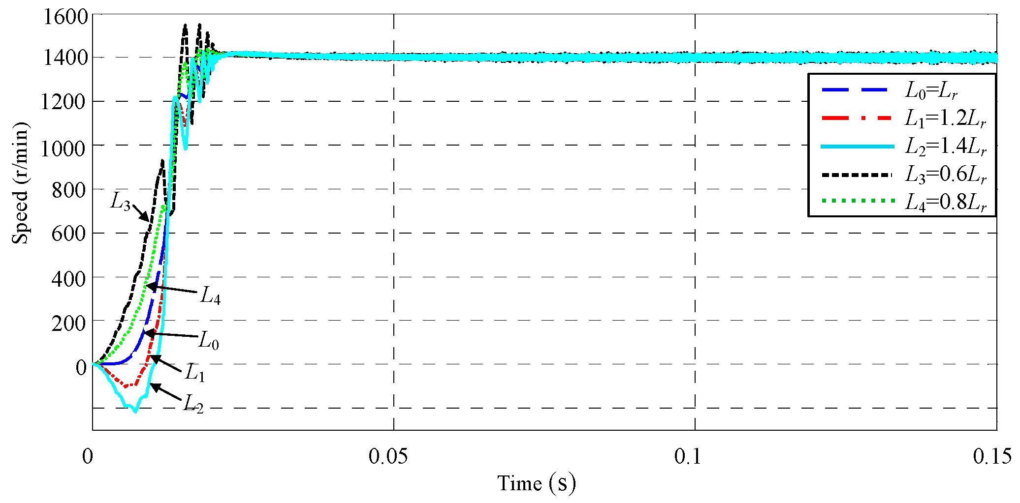
In Figure 11 and Figure 12, the variation of the rotator inductance parameters has a great influence on the Q-MRAS estimation effect. It is worth mentioning that the tracking effect of the speed estimation method based on the improved Q-MRAS may also be influenced by the variation of induction parameters, but the influence is at a small scale. The estimation system can also track the speed variation normally. From the analysis of the whole motor-controlling system, because of using the indirect control, the time constant of the motor rotor must be involved when calculating the slip frequency.
When the motor inductance changes, the time constant of the rotator will change in the same scale. So even there are no motor parameters in the estimation model, the change of the rotator inductance will also have influences on the whole sensorless speed control system.
5. Experimental Verification
In order to further study and identify the actual effect of the control system, a corresponding experimental platform has been built in this chapter and a software algorithm will also be designed. Finally, the debugging of the software and hardware has been accomplished. The running time of the interrupt subroutine is set at 0.0002 s, that is, the frequency is 5 kHz. All the vector control algorithms of the sensorless speed estimation are finished in this period of time.
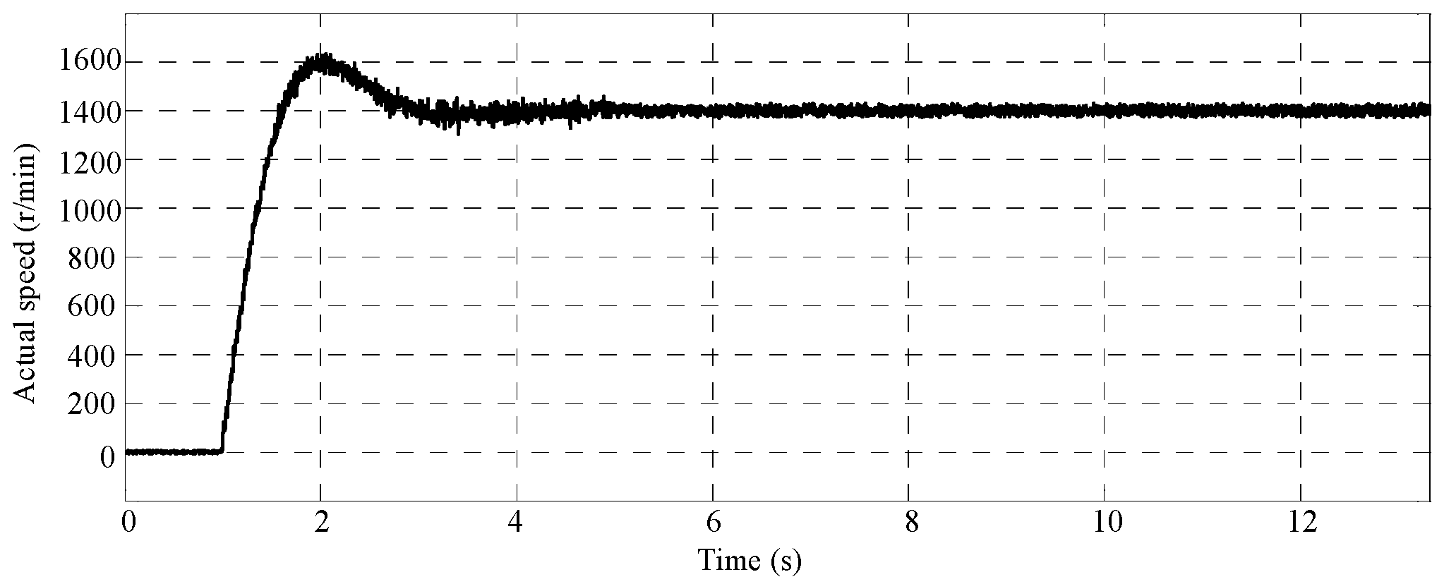
5.1. Zero-Load Startup Experiment
In the zero-load startup experiment, the given speed of the induction motor is set to 1400 r/min, and the load is set to 0 Nm.
When the two motors are connected back-to-back, and they are used as a test platform, one side of the platform is a synchronous machine, which contains a 2500 wire encoder in it. The actual speed of the induction motor can be detected by using this encoder. During this work, the output waves of the speed estimation algorithm are observed by using the View/Graph function in CCS5.5 (TMS320F28335 Delfino Microcontroller, Texas Instruments, Inc., Dallas, TX, USA). Meanwhile, the PI parameters in the adaptive structure are adjusted according to the result. The procedure is finished until the debugging has been done. The experiment results are shown below.
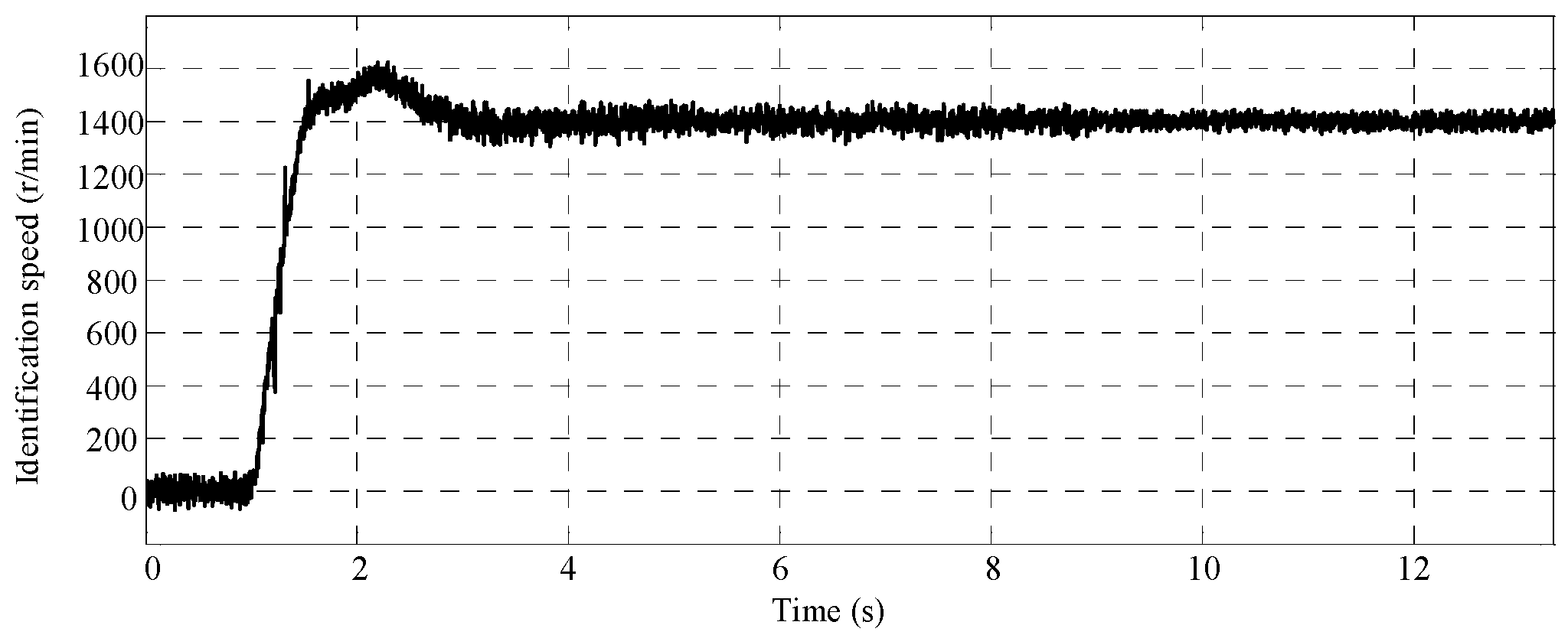
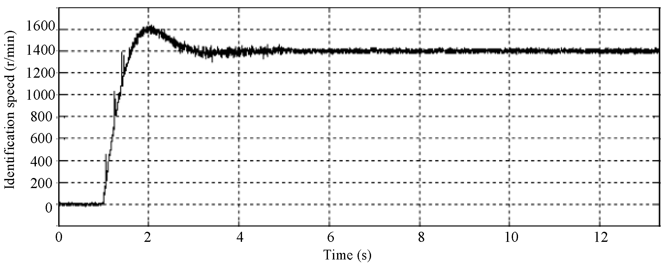
The actual speed of the induction motor is shown in Figure 13, and it is obtained by the encoder in the synchronous motor. Figure 14 and Figure 15 show the speed, which is estimated by the conventional Q-MRAS and improved Q-MRAS algorithm method, respectively. The speed estimated by these two algorithms is almost the same as the actual speed. The tracking performance of the improved Q-MRAS algorithm is better in the startup process. The error comparisons in the static process are shown in Figure 16. The error is greater in the conventional Q-MRAS algorithm, and the error usually fluctuates between −3% and 4%, while the estimation error in the steady state of the improved Q-MRAS algorithm is controlled within ±0.5%.
5.2. The Speed Mutation Experiment
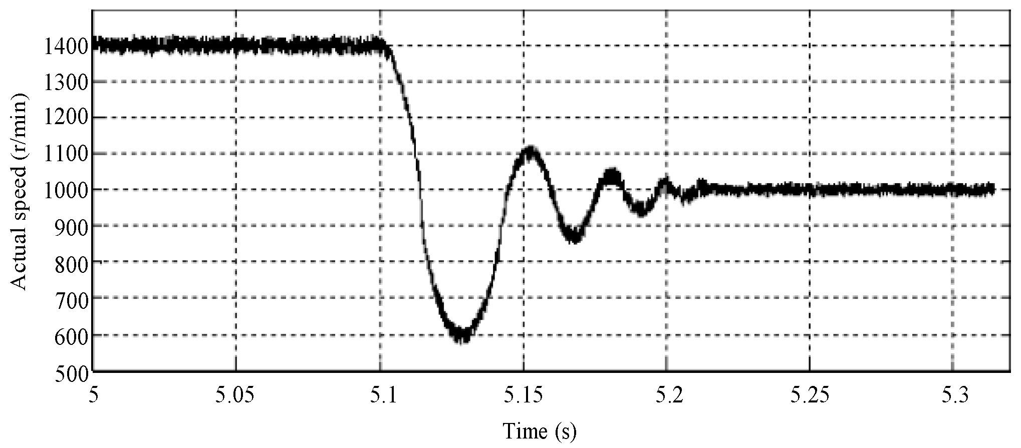
When the motor changes its state from zero load condition to the rated speed condition, the instruction speed of the motor is changed from 1400 r/min to 1000 r/min instantly. The actual speed of the motor is shown in Figure 17.
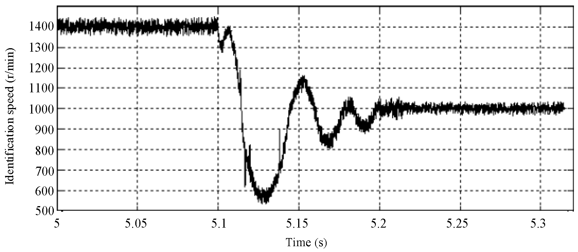
Figure 18 and Figure 19 show the estimation result in the situation of speed mutation of Q-MRAS algorithm and improved Q-MRAS method, respectively. From the two figures above, both of the methods can roughly estimate the actual speed. However, the tracking performance of the improved algorithm is better in the steady state condition and the switching state condition.
5.3. The Low-Speed Estimation Experiment
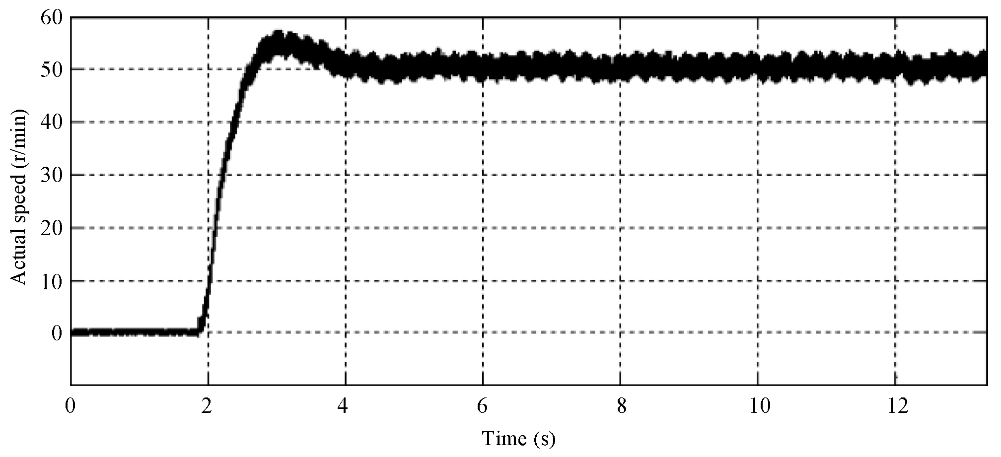
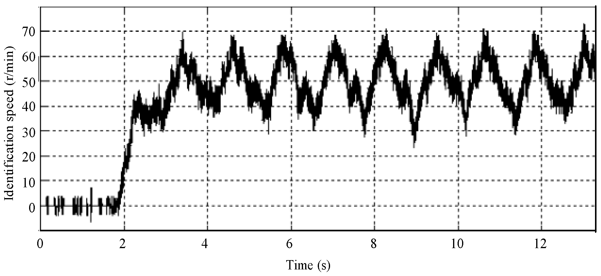
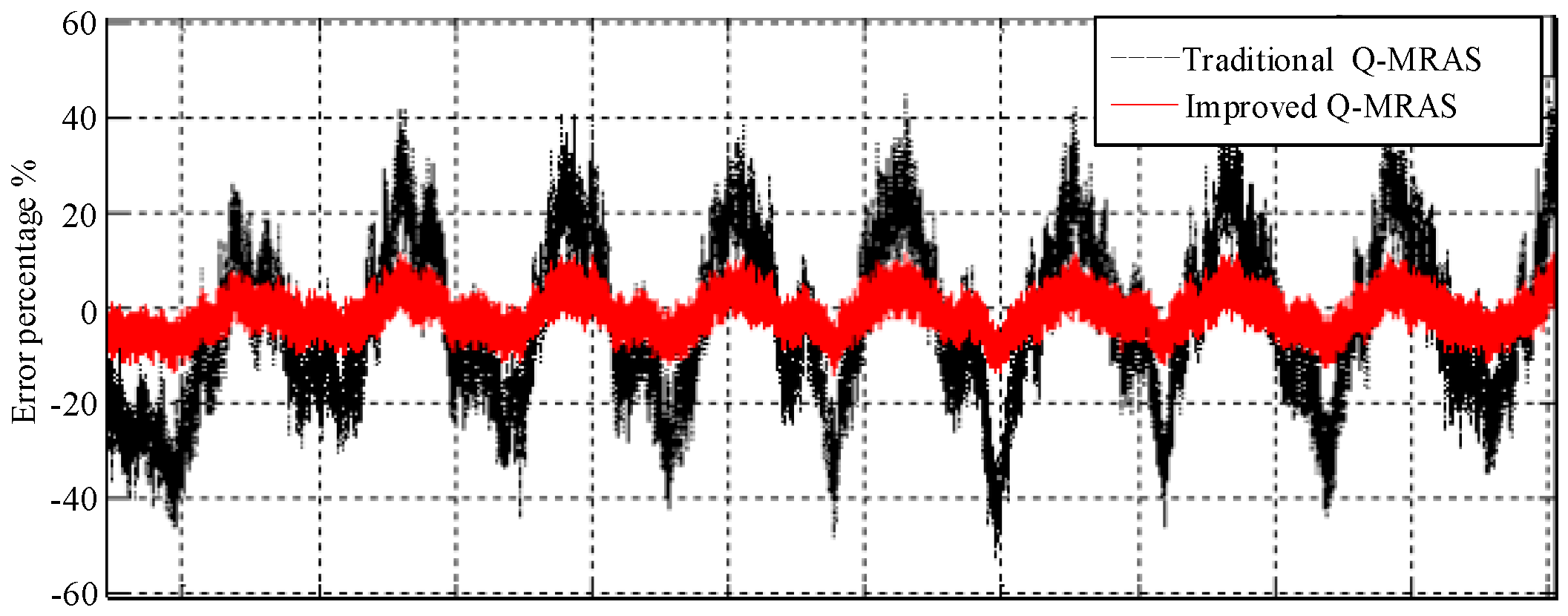
In order test the performance of the two algorithms when running in the low speed condition, the zero-load running condition is set as follows: the speed is 50 r/min and the load is 0 Nm. The fluctuation of the actual speed is shown in Figure 20. Figure 21 and Figure 22 show the estimation algorithm result of the Q-MRAS method and improved Q-MRAS method in the low speed condition. Both of the results have a greater fluctuation, but the conventional Q-MRAS speed estimation fluctuates greatly. The tracking effect declines greatly because of the distortion in the tracking process of the startup condition. However, the improved algorithm can track the speed better, which has a significant relationship with the variation of the motor parameters. The accuracy of the conventional Q-MRAS algorithm will decline. The fluctuation in the steady state of the improved Q-MRAS system is related to the variation of the rotator time constant in the indirect vector controlling system. The results of the error in the steady state are compared and analyzed in Figure 23. The fluctuation of the conventional Q-MRAS is within ±40%. The estimation accuracy of the improved algorithm in the steady state performs well in the low-speed condition.
6. Conclusions
An improved Q-MRAS speed estimation is proposed according to the problem of parameter sensitivity in the conventional Q-MRAS speed estimation method. The reactive power in the static coordinate is used as the reference model in the improved Q-MRAS speed estimation method. Meanwhile, the reactive power in the rotating coordinate is used as the adjustable model. The estimation system consisting of these two models can run steadily at the full-speed and full-load scale. In the simulation and experiment results, the tracking performance of the improved algorithm is better no matter the low-speed condition and the switching state condition.
Acknowledgments
This work was supported by the Shenzhen Science and Technology Plan Project (grant No. JCYJ20150403161923505).
Author Contributions
Danyang Bao, Hong Wang and Xioajie Wang have contributed to developing ideas about energy consumption prediction and collecting the data. Chaoruo Zhang programmed the algorithm and tested it. All the authors were involved in preparing the manuscript.
Conflicts of Interest
The authors declare no conflicts of interest.
References
- Zhang, G.; Wang, G.; Xu, D.; Yu, Y. Discrete-Time Low-Frequency-Ratio Synchronous-Frame Full-Order Observer for Position Sensorless IPMSM Drives. IEEE J. Emerg. Sel. Top. Power Electron. 2017, 5, 870–879. [Google Scholar] [CrossRef]
- Chen, W.; Yu, Y.; Yang, R.; XU, Z.; XU, D. Low Speed Stability Research of Adaptive Full-order Observer for Induction Motor. Proc. CSEE 2010, 30, 33–40. [Google Scholar]
- Orlowska-Kowalska, T.; Dybkowski, M. Stator-Current-Based MRAS Estimator for a Wide Range Speed-Sensorless Induction-Motor Drive. IEEE Trans. Ind. Electron. 2010, 57, 1296–1308. [Google Scholar] [CrossRef]
- Sheela, M.; Himavathi, S.; Santhalakshmy, S.; Venkadesan, A. Comparison of flux and real power based MRAS for inverse Rotor time constant estimation in induction Motor Drives. In Proceedings of the 2014 International Conference on Advances in Electrical Engineering (ICAEE), Vellore, India, 9–11 January 2014; pp. 1–5. [Google Scholar]
- Zhao, Y.; Qiao, W.; Wu, L. Model adaptive reference system-based speed estimators for sensorless control of interior permanent magnet synchronous machines. In Proceedings of the IEEE Transportation Electrification Conference and Expo (ITEC), Detroit, MI, USA, 16–19 June 2013. [Google Scholar]
- Yin, Z.; Zhao, C.; Zhong, Y.; Li, L.; Li, J. A Speed Estimation Method of Induction Motors Using the Robust Extended Kalman Filter. Proc. CSEE 2012, 32, 152–159. [Google Scholar]
- Yin, Z.G.; Xiao, L.; Sun, X.D.; Liu, J.; Zhong, Y. A Speed Estimation Method of Fuzzy Extended Kalman Filter for Induction Motors Based on Particle Swarm Optimization. Trans. China Electrotech. Soc. 2016, 31, 55–65. [Google Scholar]
- Zerdali, E.; Barut, M. The Comparisons of Optimized Extended Kalman Filters for Speed-Sensorless Control of Induction Motors. IEEE Trans. Ind. Electron. 2017, 64, 4340–4351. [Google Scholar] [CrossRef]
- Azza, H.B.; Zaidi, N.; Jemli, M.; Boussak, M. Development and Experimental Evaluation of a Sensorless Speed Control of SPIM Using Adaptive Sliding Mode-MRAS Strategy. IEEE J. Emerg. Sel. Top. Power Electron. 2014, 2, 319–328. [Google Scholar] [CrossRef]
- Wei, W.X.; Liu, G.Y. Sensorless Control with Flux Observer Based on Parallel Stator Resistance Adaptation and Extended State Observer Model. Proc. CSEE 2015, 35, 23–32. [Google Scholar]
- Benlaloui, I.; Drid, S.; Chrifi-Alaoui, L.; Ouriagli, M. Implementation of a New MRAS Speed Sensorless Vector Control of Induction Machine. IEEE Trans. Energy Convers. 2015, 30, 588–595. [Google Scholar] [CrossRef]
- Schauder, C. Adaptive speed estimation for vector control of induction motors without rotational transducers. IEEE Trans. Ind. Appl. 1992, 28, 1054–1061. [Google Scholar] [CrossRef]
- Wubin, K.; Jin, H.; Ronghai, Q.U.; Min, K.A.; Jian, L.I. Research on Speed Sensorless Control Strategies for Five-phase Induction Motors with Rotor Parameter Estimation. Proc. CSEE 2016, 36, 532–539. [Google Scholar]
- Rashed, M.; Stomach, A.F. A stable back-EMF MRAS-based sensorless low-speed induction motor drive insensitive to stator resistance variation. IEE Proc. Electr. Power Appl. 2004, 151, 685–693. [Google Scholar] [CrossRef]
- Peng, F.; Fukao, T. Robust speed estimation for speed-sensorless vector control of induction motors. IEEE Trans. Ind. Appl. 1994, 30, 1234–1240. [Google Scholar] [CrossRef]
- Maiti, S.; Chakraborty, C.; Hori, Y.; Ta, M.C. Model Reference Adaptive Controller-Based Rotor Resistance and Speed Estimation Techniques for Vector Controlled Induction Motor Drive Utilizing Reactive Power. IEEE Trans. Ind. Electron. 2008, 55, 594–601. [Google Scholar] [CrossRef]
- Maiti, S.; Chakraborty, C. Experimental validation of very-low and zero speed operation of a flux-eliminated adaptive estimator for vector controlled IM drive. In Proceedings of the 2009 IEEE International Conference on Industrial Technology, Churchill, Australia, 10–13 February 2009; pp. 1–6. [Google Scholar]
Figure 1.
The structure of the instantaneous reactive power (Q) based on model reference adaptive system (Q-MRAS) speed estimation system.
Figure 1.
The structure of the instantaneous reactive power (Q) based on model reference adaptive system (Q-MRAS) speed estimation system.
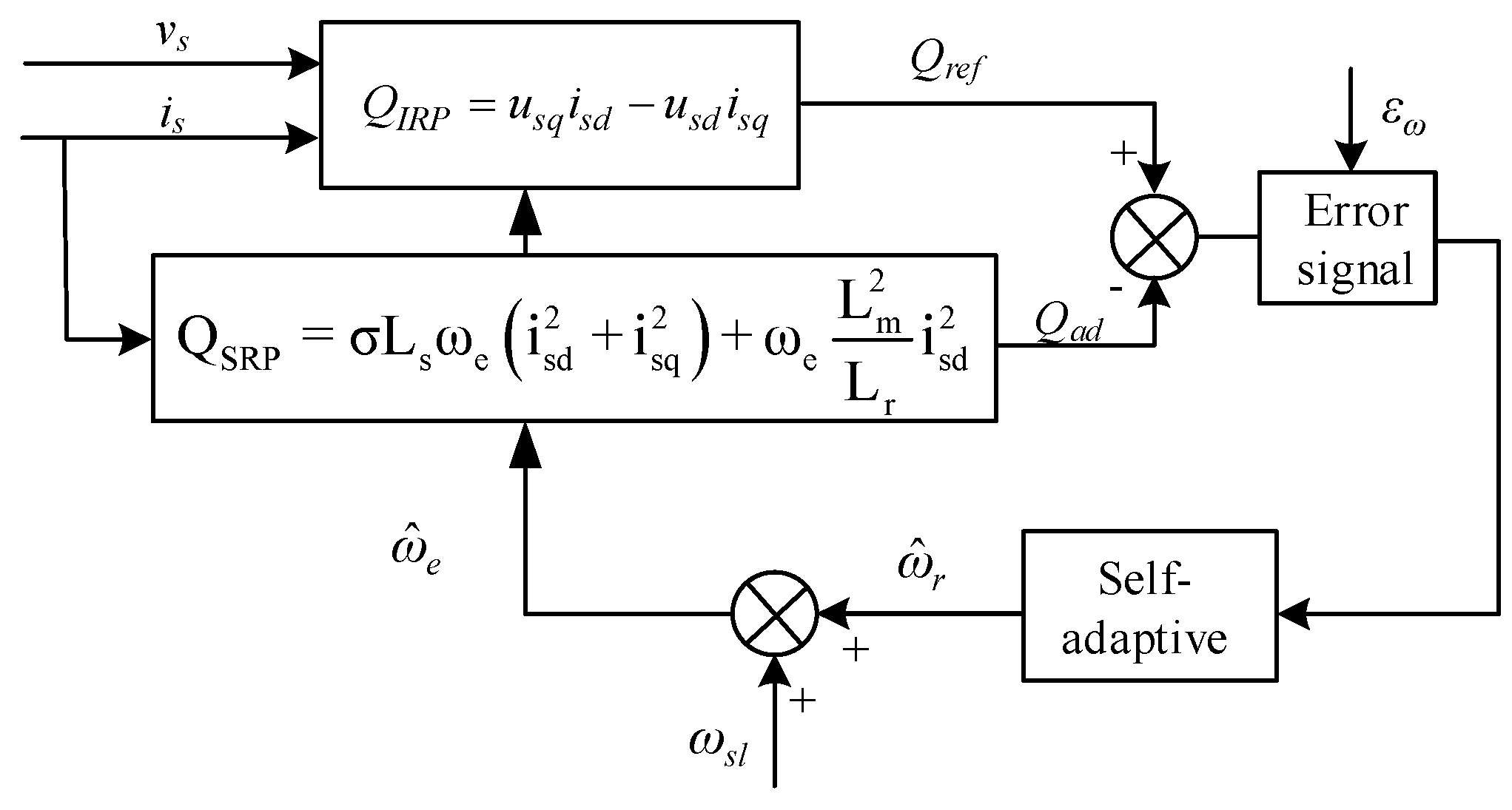
Figure 2.
The structure of speed estimation based on the improved Q-MRAS.
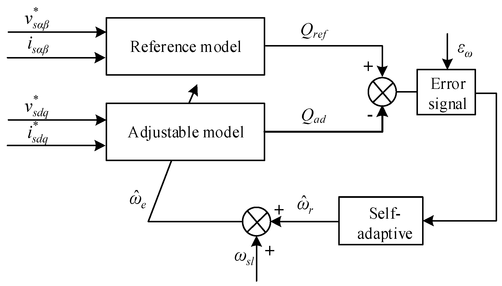
Figure 3.
The sensorless speed design diagram based on the three-level space vector algorithm Space Vector Pulse Width Modulation (SVPWM).
Figure 3.
The sensorless speed design diagram based on the three-level space vector algorithm Space Vector Pulse Width Modulation (SVPWM).

Figure 4.
(a) The structure of state space based on improved Q-MRAS system; and (b) the root locus plot of Equation (35) for the forward motoring mode.
Figure 4.
(a) The structure of state space based on improved Q-MRAS system; and (b) the root locus plot of Equation (35) for the forward motoring mode.

Figure 5.
The speed estimation result in the no-load condition.
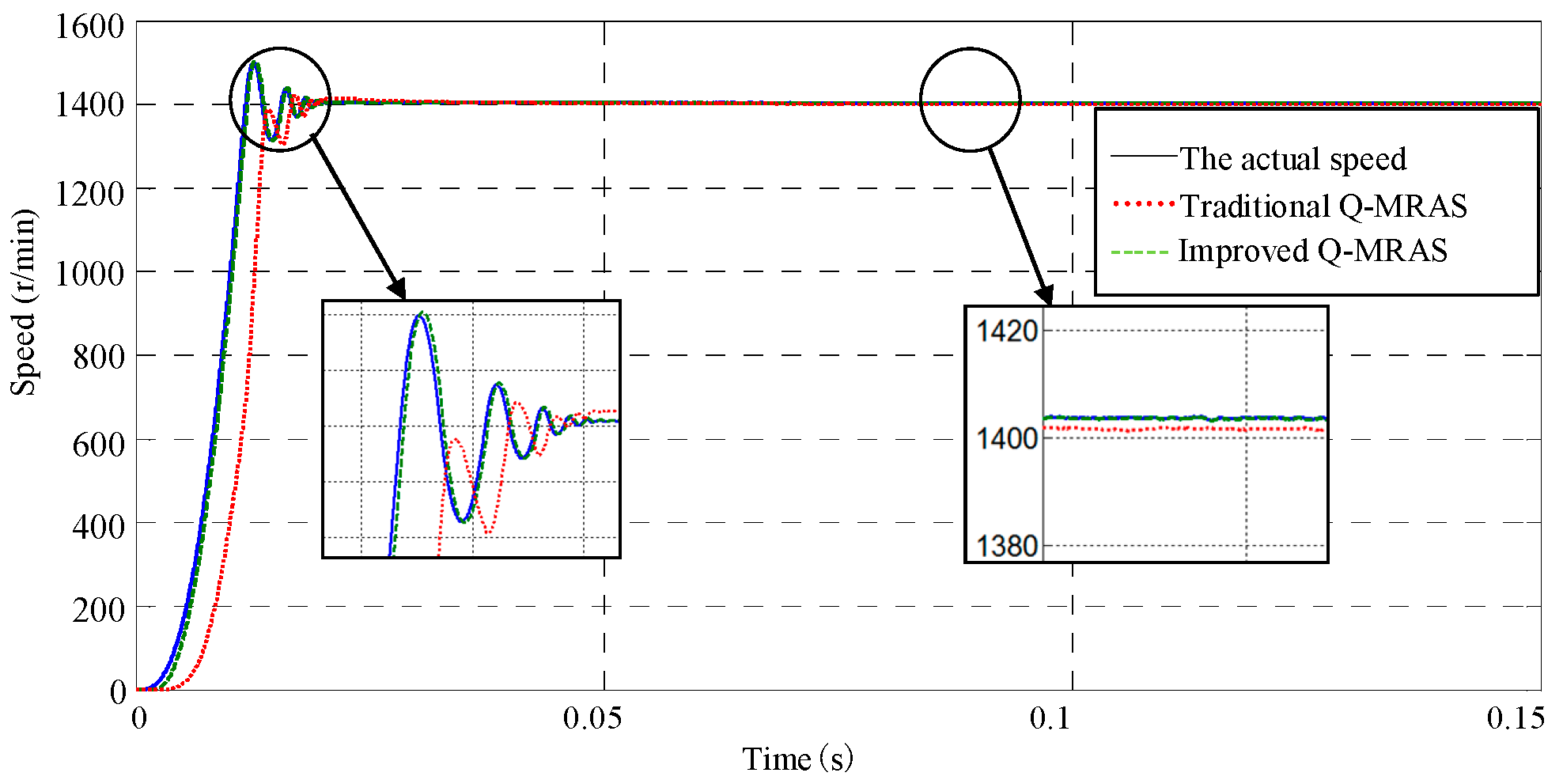
Figure 6.
The speed estimation result from no-load condition to full-load condition.

Figure 7.
The result of speed estimation in the condition of speed mutation.

Figure 8.
The speed estimation result in the low-speed condition.

Figure 9.
The influence on the Q-MRAS speed estimation method produced by the stator inductance.

Figure 10.
The influence on the improved Q-MRAS speed estimation method produced by the stator inductance.
Figure 10.
The influence on the improved Q-MRAS speed estimation method produced by the stator inductance.

Figure 11.
The influence on the Q-MRAS speed estimation method produced by the rotator inductance.

Figure 12.
The influence on the improved Q-MRAS speed estimation method produced by the rotator inductance.
Figure 12.
The influence on the improved Q-MRAS speed estimation method produced by the rotator inductance.

Figure 13.
The actual speed of the induction motor in the no-load condition.

Figure 14.
The rotation wave identified by the conventional Q-MRAS method.

Figure 15.
The rotation wave identified by the improved Q-MRAS method.

Figure 16.
The comparison of the steady-state error in the no-load startup condition.
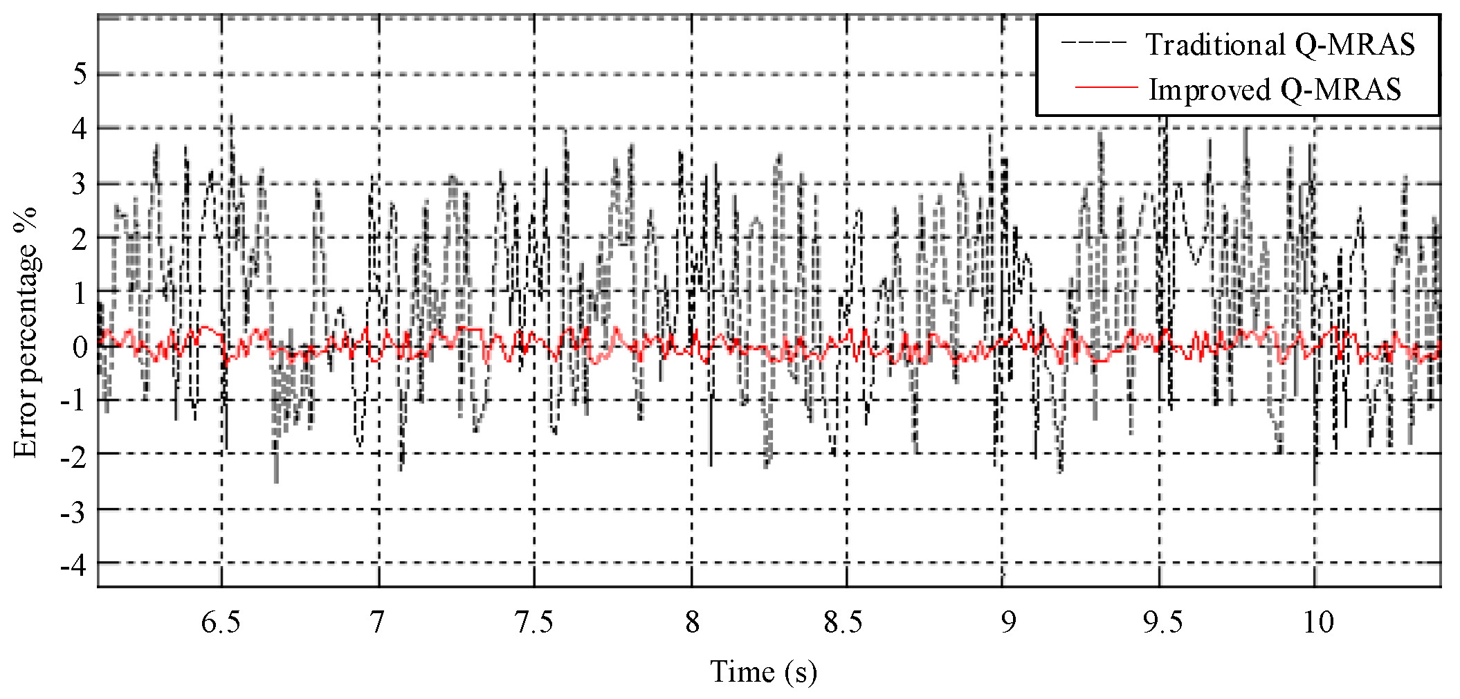
Figure 17.
The actual speed wave of the induction motor in the speed mutation condition.

Figure 18.
The estimation result of the conventional Q-MRAS algorithm in the speed mutation condition.
Figure 18.
The estimation result of the conventional Q-MRAS algorithm in the speed mutation condition.

Figure 19.
The speed estimation result of the improved Q-MRAS algorithm in the speed mutation condition.
Figure 19.
The speed estimation result of the improved Q-MRAS algorithm in the speed mutation condition.

Figure 20.
The actual speed of the induction motor in the low-speed condition.

Figure 21.
The speed estimation algorithm result based on the conventional Q-MRAS in the low-speed condition.
Figure 21.
The speed estimation algorithm result based on the conventional Q-MRAS in the low-speed condition.

Figure 22.
The speed estimation algorithm result based on the improved Q-MRAS in the low-speed condition.
Figure 22.
The speed estimation algorithm result based on the improved Q-MRAS in the low-speed condition.
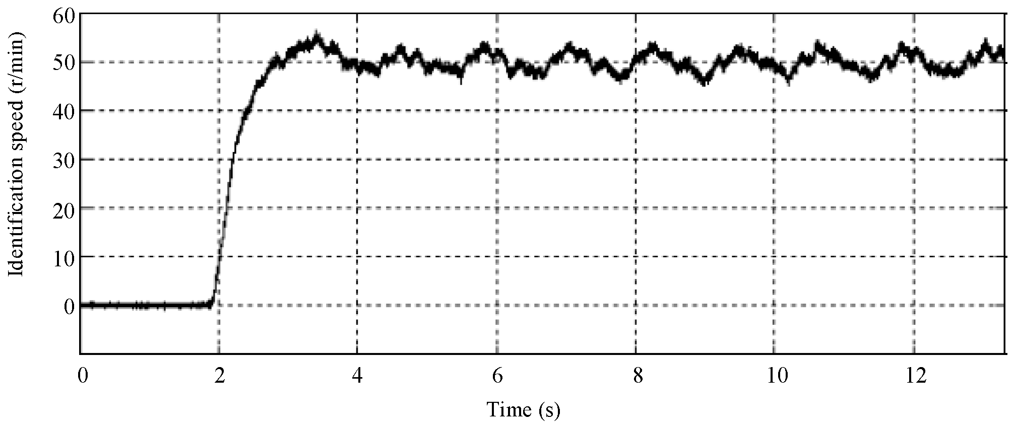
Figure 23.
The comparison and analysis of the error in the steady state in the low-speed condition.
© 2018 by the authors. Licensee MDPI, Basel, Switzerland. This article is an open access article distributed under the terms and conditions of the Creative Commons Attribution (CC BY) license (http://creativecommons.org/licenses/by/4.0/).
Share and Cite
MDPI and ACS Style
Bao, D.; Wang, H.; Wang, X.; Zhang, C. Sensorless Speed Control Based on the Improved Q-MRAS Method for Induction Motor Drives. Energies 2018, 11, 235. https://doi.org/10.3390/en11010235
AMA Style
Bao D, Wang H, Wang X, Zhang C. Sensorless Speed Control Based on the Improved Q-MRAS Method for Induction Motor Drives. Energies. 2018; 11(1):235. https://doi.org/10.3390/en11010235
Chicago/Turabian StyleBao, Danyang, Hong Wang, Xiaojie Wang, and Chaoruo Zhang. 2018. "Sensorless Speed Control Based on the Improved Q-MRAS Method for Induction Motor Drives" Energies 11, no. 1: 235. https://doi.org/10.3390/en11010235
Note that from the first issue of 2016, this journal uses article numbers instead of page numbers. See further details here.