Hydration of Magnesium Carbonate in a Thermal Energy Storage Process and Its Heating Application Design †

Thermal and Flow Engineering Laboratory, Åbo Akademi University, 20900 Turku, Finland
*
Author to whom correspondence should be addressed.
†
This article is based on our paper, presented at ECOS 2017, 2–6 July 2017.
Energies 2018, 11(1), 170; https://doi.org/10.3390/en11010170
Submission received: 21 December 2017
/
Revised: 8 January 2018
/
Accepted: 8 January 2018
/
Published: 11 January 2018
(This article belongs to the Special Issue Selected Papers from ECOS 2017—30th International Conference on Efficiency, Cost, Optimisation, Simulation and Environmental Impact of Energy Systems)
Abstract
:First ideas of applications design using magnesium (hydro) carbonates mixed with silica gel for day/night and seasonal thermal energy storage are presented. The application implies using solar (or another) heat source for heating up the thermal energy storage (dehydration) unit during daytime or summertime, of which energy can be discharged (hydration) during night-time or winter. The applications can be used in small houses or bigger buildings. Experimental data are presented, determining and analysing kinetics and operating temperatures for the applications. In this paper the focus is on the hydration part of the process, which is the more challenging part, considering conversion and kinetics. Various operating temperatures for both the reactor and the water (storage) tank are tested and the favourable temperatures are presented and discussed. Applications both using ground heat for water vapour generation and using water vapour from indoor air are presented. The thermal energy storage system with mixed nesquehonite (NQ) and silica gel (SG) can use both low (25–50%) and high (75%) relative humidity (RH) air for hydration. The hydration at 40% RH gives a thermal storage capacity of 0.32 MJ/kg while 75% RH gives a capacity of 0.68 MJ/kg.
1. Introduction
A number of renewable heat sources are not available when needed or do not meet the fluctuating demand for heating. During summer, the thermal solar heat output great exceeds the heating demand. Solving this problem requires seasonal storage, in the form of thermal energy storage (TES), within affordable boundaries. Moreover, in district heating systems, the seasonal storage possibility lowers the investment costs for plants in use during peak hours, and more thermal solar heating can be introduced to the system.
Using reversible chemical reactions for storage gives the highest energy density. However, this requires heat sources at 200–1000 °C, which is not applicable in most heating systems [1]. Thermal storage of heat in big water or gravel tanks has been widely tested, having a 60% efficiency (re-use of stored energy) and requiring large storage volumes underground [2]. Chemical sorption reactions require lower temperatures and are more energy dense compared to water storage tanks and require temperatures of 50–150 °C in a TES system.
Studies show that zeolite Na-Y can be used for a TES with a heat capacity 1.0 MJ/kg requiring a dehydration temperature of 140 °C. The heat capacity can be increased to 1.1 MJ/kg by combining it with 15%-wt MgSO4, which in itself has a theoretical heat capacity of 1.74 MJ/kg [3]. However, MgSO4 has been shown to not offer its full sorption capacity when precipitated in zeolites [3,4]. Zeolite H-Y has a 40 °C lower dehydration temperature, with a heat capacity of 0.8 MJ/kg [4]. TES with dehydration of MgCl2·6H2O to MgCl2·2H2O gives theoretically a capacity of 2 GJ/m3 however; using a packed bed design in the reactor with porosity of 50% reduces the capacity to 1 GJ/m3, and a practical test gave an efficiency as low as 0.5 GJ/m3 [5].
Magnesite (MgCO3) and water vapour form nesquehonite (NQ) (MgCO3·3H2O) according to reaction (R1) or lansfordite at temperatures below 5 °C according to reaction (R2) [6,7,8]. The NQ is potentially an inexpensive resource considering it can be produced in a carbon capture and storage mineralisation (CCSM) process [8,9,10,11]. Magnesium can be extracted from serpentine mineral and carbonated in a water solution with CO2 gas, forming nesquehonite [8]:
MgCO3 + 3H2O(g) ↔ MgCO3∙3H2O ΔH = −1.00 MJ/kg MgCO3∙3H2O, T = 298 K
MgCO3 + 5H2O(g) ↔ MgCO3∙5H2O ΔH = −1.41 MJ/kg MgCO3∙5H2O, T = 298 K
Moreover, the NQ can operate in lower temperatures compared to MgSO4, and does not require operation at a low pressure like MgCl2 and CaCl2 do. NQ can absorb heat by loss of crystallization water, preferably at 65 °C, or at temperatures as low as 50 °C, while MgSO4 requires temperatures above 122 °C [4,12,13]. The lower operating temperatures increase the efficiency of solar thermal collectors (solpanels). Another advantage, in cases where the systems are placed on houses, is that NQ is considered to be a fire retardant, as it releases CO2 and H2O when heated [14].
Zeolites are considered to be very expensive materials for TES, while salts tested for TES are much less expensive [5]. Studies by others have shown that also silica gel (SG) can be used for this purpose instead of zeolite [4,15,16]. In this study SG is used, considering not only the lower price, but also the lower dehydrating temperature compared to zeolite which makes it more suitable to work with NQ. Dehydration of zeolite takes place at temperatures between 100 and 140 °C [3]. SG is fully dehydrated at ~100 °C, however, at 65 °C (matching NQs dehydration temperature) SG is close to fully dehydrated, which is not the case with zeolite [3,13]. This offers a better applicability with district heating operating at 50–110 °C temperatures, depending on whether it is primary or secondary district heat. Table 1 gives an overview of suitable materials and their performance.
The theoretical storage capacity of the sorption reactions in this case are 1.0 MJ/kg for nesquehonite and 0.62 MJ/kg for silica gel [6,15]. Dehydration temperatures used for NQ dehydration tests at 65 °C give a capacity of 0.52 MJ/kg. The dehydration part of the process is quite straightforward, with the possibility of releasing all crystallization water in 2 h, if needed. The reverse reaction, hydration of magnesite (MgCO3), is more challenging considering conversion and kinetics. Our recent experiments with 50%/50% NQ (with mass equivalent to MgCO3)-SG mixtures gave a calculated storage capacity of 0.41 MJ/kg and after 24 h hydration, being 2.4 times larger than heating up a similar mass of water from 20 °C to 60 °C [13].
The reason for mixing NQ with SG is to create a better solid structure for contact between (hydrated) magnesium carbonate and humidity as the challenge in this process is the hydration rate and conversion, while preventing water from forming a liquid phase [13].
2. Conceptual Design
2.1. Heat Storage and Heating System Concept Using Ground Heat
Our recent studies have shown that at temperatures of 50–65 °C the dehydration (charging heat by releasing crystallization water) of NQ, forming MgCO3 is possible for TES system purposes. For hydration of MgCO3, discharging heat, temperatures as low as 5–25 °C have shown to be suitable [13]. This reversible reaction can be used for a TES according to Figure 1. Obviously, any heat source with a temperature of at least 50 °C is suitable for charging the system (i.e., dehydration). However, to take advantage of the system, heat sources not meeting demand by the hour should nonetheless be used, as both given in Figure 1. Therefore, solar heat and district heat using primarily renewable energy sources are the obvious heat sources, but excess heat from the cooling of houses or other buildings could also possibly be used if its temperature is above 50 °C.
In the case district heating is coupled with the system, with or without solar heat, the storage can be a part of a smart district heating system located close to the end users. In this case the use could depend on over- and under capacity available. The process could also possibly be connected to district cooling, if a heat pump is used for the cooling, and excess heat is produced.
When the heat storage step takes place, dehydrating NQ and SG in the reactor, it releases large amounts of water, resulting in humid air, which is partly condensed in a heat exchanger with the water being collected in a water tank, while the remaining dry air is sent back to the reactor, according to Figure 1. The condensation heat can be re-used for dehydration or for producing hot water if needed. In the heat-discharging step, the water tank located underground uses ground (geothermal) heat for evaporating water, which can be used for hydration of MgCO3 and SG in the reactor. The reactor gives an operating temperature of 15–25 °C, which requires a heat pump to increase the temperature to 35 °C for its usage in a modern house heating system. The low temperature rise in the heat pump would give approximately double the COP (coefficient of performance) compared to a normal ground heat pump, operating with the double temperature difference from 5 to 35 °C, which also decreases the investment cost of the compressor. The yearly average COP of a ground heating system in the Nordic countries is typically between 2.8 and 5, depending on the type and manufacturer [17]. Moreover, this system would give an extra advantage compared to air heat pumps for outside temperatures below 0 °C. In houses using solar heat, the stored heat can be used during night, or during ambient winter when temperature is e.g., below 0 °C, decreasing the required heat pump capacity. In larger houses or larger district heating systems, the usage can be centrally controlled, as more heat sources in district heating are close to the user.
2.1.1. Design of Heat Storage Process
Studies showed that a COP of 1.7–6.8 can be achieved in an open system adsorption TES, using a simple electrified humidifier [18]. Aydin et al. concluded that humidification applied to adsorption TES with low energy input requirement is challenging [19]. In order to use ground heat (at 5 °C) for evaporating the water needed for hydration, the humid air has to be pressurised to a few bar at low temperatures to reach a sufficient relative humidity (RH) for complete hydration. Shown in Figure 1, the relative humidity is increased in the evaporator containing a bubble column resulting in a RH close to 100%. The air is then heated up to the temperature in the reactor by air leaving the reactor for the evaporator in a heat exchanger. In this case, the reactor temperature is 20 °C giving a RH of 36%, which is not enough for the maximum hydration. In Figure 1 to the left, the temperature and RH of two cases (identified as 1 and 2.) are shown. The first one is the case explained above, while the second one is providing the reactor with the RH (70–75%) for maximum results obtained in earlier studies [13].
To provide 72% RH (0.011 kg H2O/kg dry air) hydration air, the evaporator operates at 5 °C and 100% RH requires a pressure of 2 bar. Shown in Figure 1, this requires a compressor (C), which will increase the temperature to 82 °C or 50 °C when using one stage or two-stage compression, respectively. The air is cooled to 5 °C before the evaporator in a heat exchanger by the air leaving the evaporator and heated to the 82 °C or 50 °C mentioned. It then goes to the turbine, decreasing the pressure and temperature to 1 bar and 20 °C, returning the energy as work to the compressor. As a result less external electricity is required, according to the scheme to the left in Figure 1. However, this would be the case when maximum hydration is achieved, and case 1 is at the start of the hydration. Studies have shown that the concept of using ground heat for evaporating water for hydration is sufficient [5]. However, these tests were done in the Dutch climate giving a 10 °C ground heat temperature, which is considerably higher than the 5 °C (approximately 0–5 °C in southern Finland) used in this study. The higher ground temperature in the regions of central Europe (and similar climates) would decrease (or remove) the need of pressuring the evaporator. In this study, the hydration performance at different RH are tested to determine the pressures needed for operation of the evaporator, which is reported in Section 4. Further process operation opportunities will be discussed in Section 4.2 and Section 4.4.
2.1.2. Charging Process
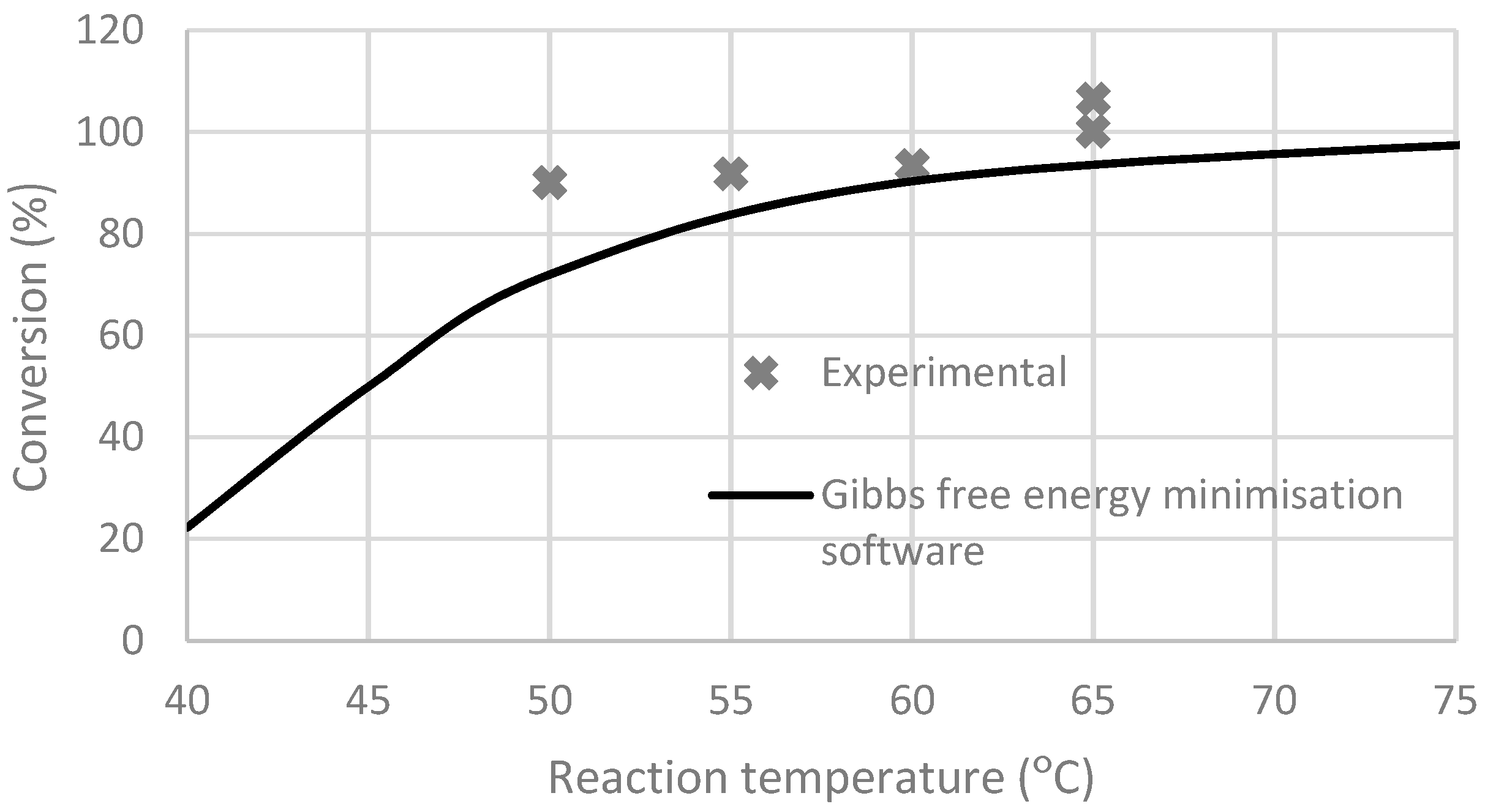
The charging process of the heat storage, dehydration of NQ and SG, is relatively simple. Shown in Figure 1 (to the right), as the reactor content heats up to 50–65 °C, crystal water is released from NQ forming MgCO3 and absorbed water from the pores in SG. The water is cooled to the temperature of the water collector and condensed in a heat exchanger/condenser, heating up the chilled air (RH 100%) pumped from the water collector to 50–65 °C resulting in a RH of 5–10%. The air flow is minimized to avoid heat losses in the system. As mentioned earlier, the most preferable temperature for dehydration is 65 °C however, at least 50 °C is required. In Figure 2, showing results from earlier studies, the dehydration conversion was 100% and 106% at 65 °C. The result giving conversion larger than 100% is presumably caused by incomplete drying during the preparation, or lansfordite was formed in the precipitation of NQ, which was the reason why one more test was done at 65 °C. Hydration at temperatures 50–60 °C gives conversion levels of about 90% [13].
Since the temperature of 65 °C might not (always) be available, the reactor should be divided in sections. In order to store heat if only 50 °C heat is available, a different section could be used than if 65 °C heat is available while the reaction stage of dehydrating from 90 to 100% is ongoing. Moreover, using such sections can avoid heat output problems, as the kinetics of the reaction may differ depending on the conversion grade. The sections can also be useful with day/night heat storage and seasonal storage working simultaneously. Also, different loads on the compressor during hydration could be applied by using various sections in different stages of the hydration, requiring varying RH dependent on evaporator pressure, which is discussed further in Section 4.2 and Section 4.4. The relative humidity during the hydration is crucial for the performance of the system.
Studies show that thermal storage of heat in certain water and gravel systems gives energy (heat) losses of 60% [2]. In the here proposed system, the reactor would have only small heat losses to the ambient, as the unused reactor section can reach ambient temperature. Stopping the airflow during hydration or dehydration stops the reactions. In this concept the air system is closed and a few percent of the air needs to contain CO2, for NQ not to release CO2 and form hydromagnesite (HM) (Mg5(OH)2(CO3)4·4H2O), which would not form magnesite by dehydrating [7,8].
2.2. TES Combined with Exhaust Air Heat Pump
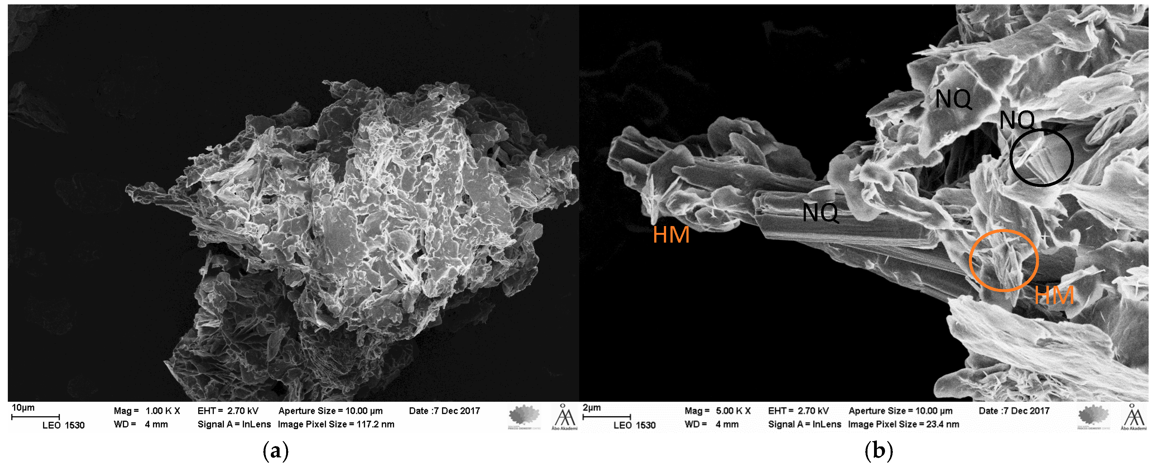
Our recent studies showed that the formation of HM in NQ samples is very slow at room temperature (21 °C). Samples were kept for 1 week, 2 weeks and 2 months under atmospheric conditions for comparison with the original sample. The risk of emitting 1 out of 5 CO2 from NQ resulting in HM (not reversible) can be monitored by scanning electron microscopy (SEM) [9,20,21]. As mentioned earlier, according to Hill et al. NQ forms HM if stored under 1% of CO2 at 25 °C, and under 0.1% of CO2 at 10 °C although, the rate of this process seems to be unknown [7]. In Figure 3, dried NQ without aging is shown and in Figure 3a, a two months aged material stored without excess CO2, showing no visible amounts of HM. In Figure 3b, the sample used for 20 tests is shown, and the NQ is clearly visible although, also rose-alike clusters are visible. According to other researchers, NQ crystals are needle shaped and HM crystal are shaped as irregular flakes in spherical clusters [21,22]. Moreover, the amount of HM seems not to affect the cyclabilty and hydration of the sample (Named Sample 1 Section 4).
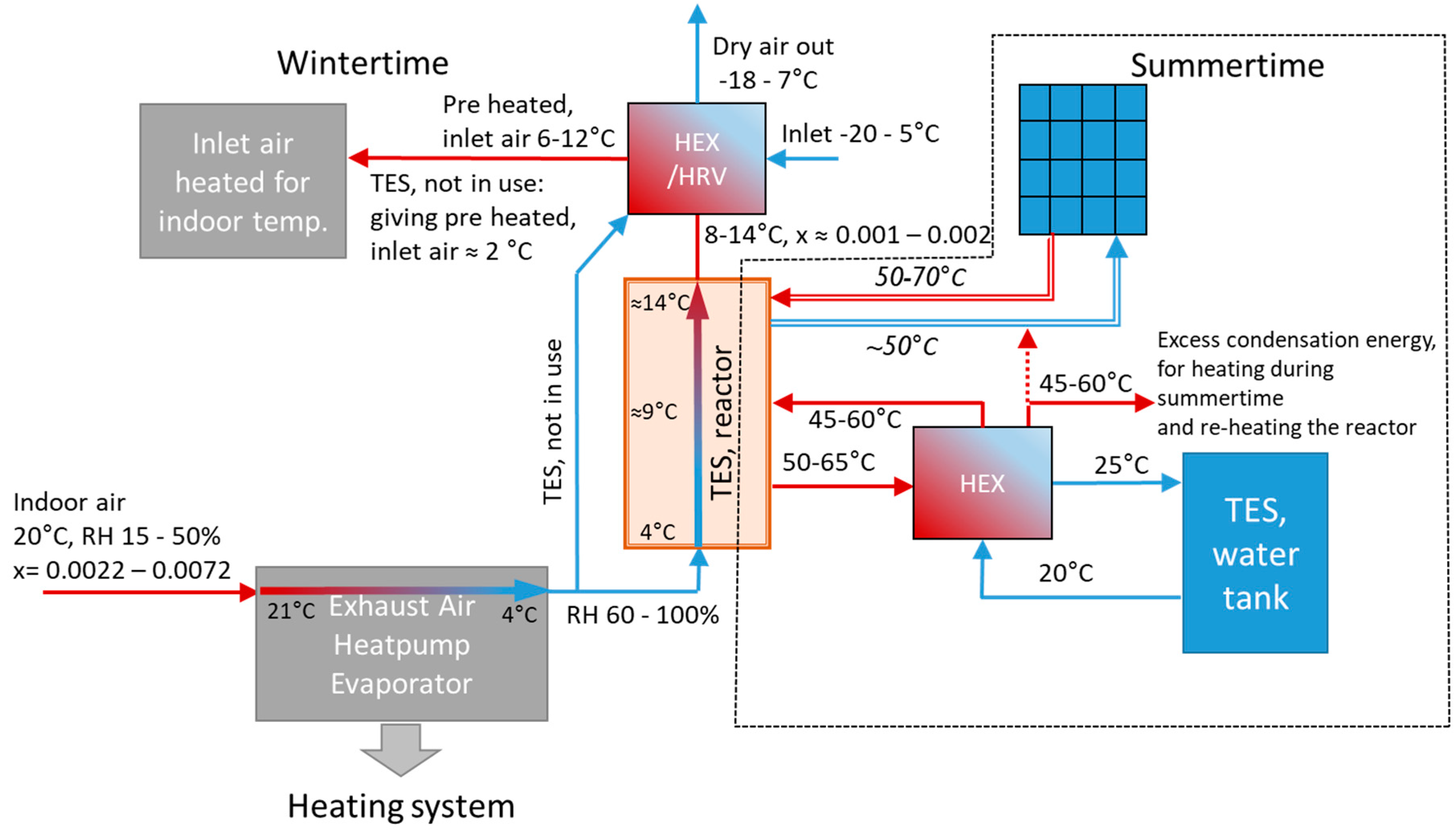
Presumably, the formation of hydromagnesite occurs at high temperatures during dehydration, and hydration without excess CO2 is possible without losing cyclability. This is why a simpler (less expensive) concept is also presented, without excess CO2 during hydration. TES coupled with an exhaust air heat pump (EAHP) was developed, shown in Figure 4. TES using water vapour from the indoor air, of which heat is used for the EAHP and is chilled down to 4 °C, giving a suitable 60–100% RH for the hydration of NQ and SG is shown in the scheme in Figure 4. The temperature rises by 5–10 °C, depending on the available content of water vapour (giving heat when reacting with NQ mixed with SG according to R1) per mass air heated air. This is used for preheating the inlet air, and less energy for heating inlet air is then demanded from the heating system. Basically, the water vapour source for chemisorption is excess moisture from indoor activities (shower etc.) and the outdoor air, considering that the outlet air is drier than the inlet air (due to the water vapour adsorption in the TES).
EAHP often requires an auxiliary plant or heat source and for colder days [23]. Considering this, the heat stored during summer in a TES could be used as an assisting heat source where EAHPs are used during winter. Studies show that a modern EAHP can have a COP of 3 for producing domestic heating water and 3.4 when providing heat for floor heating [24]. During colder days, the COP of the total system could be increased using more heat, considering that the TES discharge only requires one extra fan as electricity input.
As benefits of the concept, compared to the one presented in Figure 1, no compressors and no underground water tank are required and only one more heat exchanger is needed during the hydration. The dehydration processes for both concepts are similar although a small CO2-bottle is required to inject an amount for 3% of CO2 in the reaction air/gas when the dehydration season begins. During the summertime, dehydration period, the system will be closed. However, it will be limited by the operation of the EAHP. The reactor in this concept could also contain other compound with water vapour-adsorbing properties.
3. Experimental Design and Procedure
3.1. Production of Nesquehonite
As mentioned earlier, nesquehonite (NQ) is a product of a CCSM process and precipitated in a solution containing MgSO4 into which ammonia and CO2 are absorbed [8,9,10,11]. At temperatures above 50 °C hydromagnesite (HM) and ammonium sulphate are formed according to reaction (R3) and below 50 °C NQ and ammonium sulphate are formed [8,20,21]. Moreover, if the CO2 vapour pressure is below 0.01 bar at lower temperatures reaction (R3) is favoured over reaction (R4) [8].
5MgSO4(s) + 10H2O(l) + 10NH3(g) + 4CO2(g)
↔ Mg5(OH)2(CO3)4·4H2O(s) + 5(NH4)2SO4(aq)
MgSO4(s) + 2NH3(g) + CO2(g)+ 3H2O ↔ MgCO3·3H2O(s) + (NH4)2SO4(aq)
A 0.5 L solution of 0.8 mol/L MgSO4 with CO2 gas bubbled until reaching a pH of 4.5 was prepared. Then, 40 ml 25%-wt ammonia in water was added to increase the pH, and NQ started to precipitate at pH 9.3 and the final pH value was 9.6. The precipitate was filtered and washed to remove any unreacted MgSO4. Dried MgSO4 forms an impenetrable crust, which was found to decrease the hydration capacity in MgSO4-zeolite mixtures [4]. Our earlier studies showed that several washing steps were required using this NQ preparation method, as presumably a MgSO4 crust decreases the hydration capacity of NQ-silica Gel (SG) mixtures [13].
3.2. Preparation of Nesquehonite and Silica Gel Granule Mixture Samples
The contact between NQ and SG and between SG and the humid air is important for sufficient hydration. Three samples with the mass ratios of 5 g-1 g, 4 g-2 g and 3 g-3 g of NQ (equivalent to dehydrated NQ) and dry SG mixtures in granules of 3–6 mm were prepared. For the granulation, wet SG, powdered NQ and added 1 g water were shaken on a sieve for the size 0.5 mm. Before the hydration tests, the samples were dehydrated at 65 °C.
3.3. Hydration Experiments
In order to simulate the reactor in the process shown in Figure 1, tests with various RH were made with the NQ/SG samples. A ~20 cm high water filled bubble column was located in an isolated box, enabling regulation of the temperature of the bubble column with a heated plate or ice cubes, and to control the RH in the test. Instead of increasing the pressure in the bubble column to reach higher RH as described Section 2.1.1, according to Figure 1, the temperature of the bubble column was adjusted.
The results of this test shows the hydration efficiency at different moisture levels, which can be calculated to the pressure needed for a certain hydration level. The humid air containing 3% CO2 is pumped from the bubble column to the reactor however. Again, the air in the reactor is pumped into the bottom of the bubble column through a porous metallic cylinder for sufficient bubble distribution. No heat exchanger shown in Figure 1 was used, as the pipes between the bubble column and the reactor were not insulated and the air flow was low (0.1 L/min), considering that the main objective for the experiments at this point was to determine the hydration performance and not (yet) the energy efficiency.
To test the kinetics and conversion of the NQ/SG mixed granules according to Figure 4 (TES combined with EAHP), the sample was placed in a cooled box at a temperature around 10 °C and the correct RH, as no additional CO2 was supposed to be present. The same test was done at 20 °C for comparison with the test done in air with added CO2.
4. Results
4.1. Relative Humidity Dependent Hydration
The aim of the hydration tests to determine the hydration of dehydrated NQ (MgCO3) forming crystal water, and SG absorbing water vapour. Several tests for determining the hydration performance on, 50%-wt/50%-wt dehydrated NQ and dry silica gel (NQ+SG), dependent on RH between 25% and 85% with sample 1 were done. The best results of NQ+SG were obtained with RH 75%, varying between a mass increase of 0.25 g/gsample and 0.29 g/gsample, while increasing the RH to 85% did not increase the hydration. Tests at lower moisture levels with the RH of 40, 46 and 52% showed a mass increase between 0.14 g/gsample and 0.19 g/gsample. However, the fluctuation of the hydration performance in this range is large, considering that the best result is 35% larger than the smallest. At lower RH (25%), a mass increase of 0.093 g/gsample was obtained, indicating that NQ adsorbs moisture at very low RH.
Noticeably, the mass increase of NQ+SG and SG reference samples give fairly similar results in terms of mass increase at RH 75%, while at RH 40–52% the SG seems to hydrate considerably more than the NQ+SG mixture. This suggests that NQ incorporates less water vapour than SG at RH 40–52%. The theoretical maximum for reaction R1 is 0.64 g/gsample and, approximately 0.35 g/gsample for water trapped in SG, if heated to 105 °C. The best result of this sample NQ+SG obtained the same mass increase as the reference SG and assuming both components hydrating equally well, gives a calculated heat storage capacity of 0.49 MJ/kg.
All of the tests shown in Figure 5 were done with the same sample of NQ+SG mixture granules and reference sample of SG. The granules and the reference SG sample have been used for twenty tests during a period of one year, with no significant change in hydration capacity or rate.
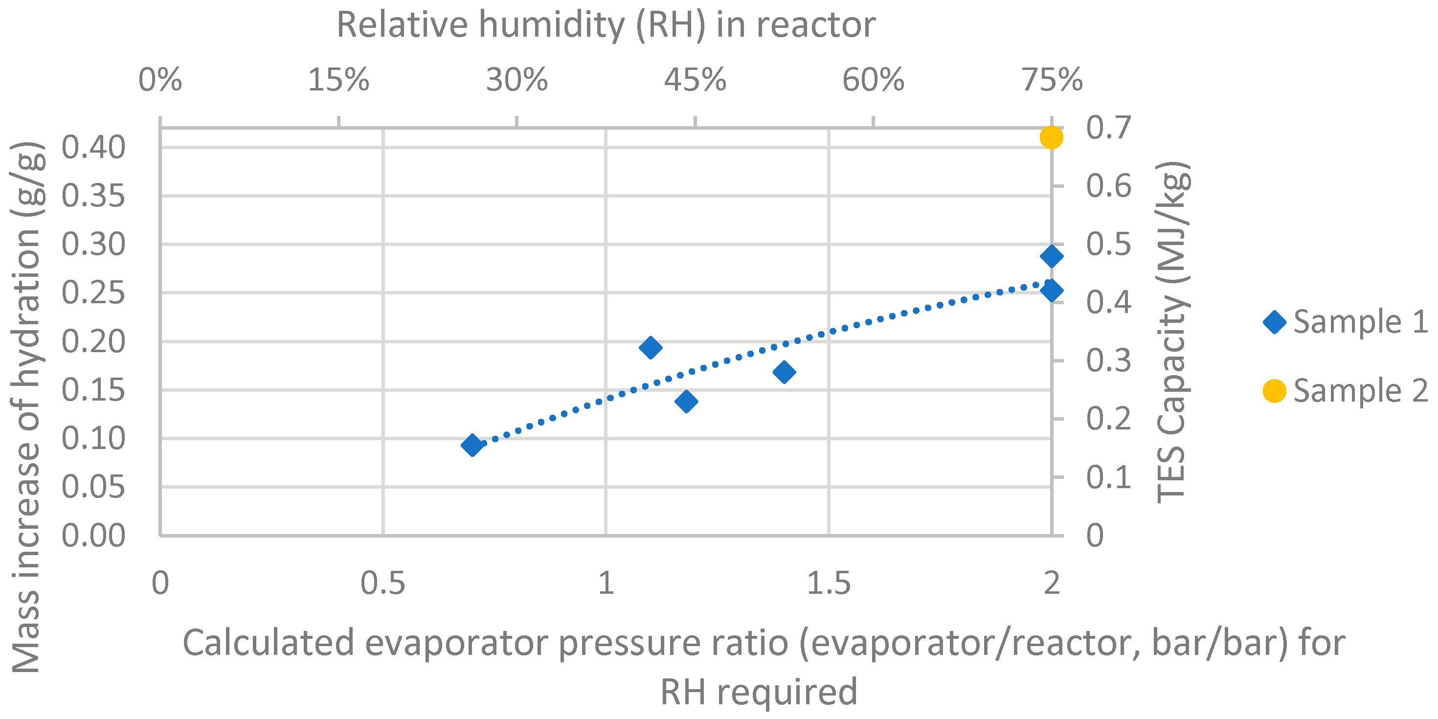
Two test were done with sample 2 at RH of 25–30% and 75%. Shown in Figure 6, the higher RH resulted in a hydration of 0.41 g/gsample giving a calculated heat storage capacity of 0.68 MJ/kg, which is near four times larger than the capacity of heat storage using the same mass of water with ∆T of 40 °C. The result is significantly better than sample 1 (0.49 MJ/kg) and results from our earlier studies (0.41 MJ/kg) [13].
However, depending on the bulk density and design of the material placed in the reactor e.g., as a packed bed, the volumetric storage compared to water capacity can vary.
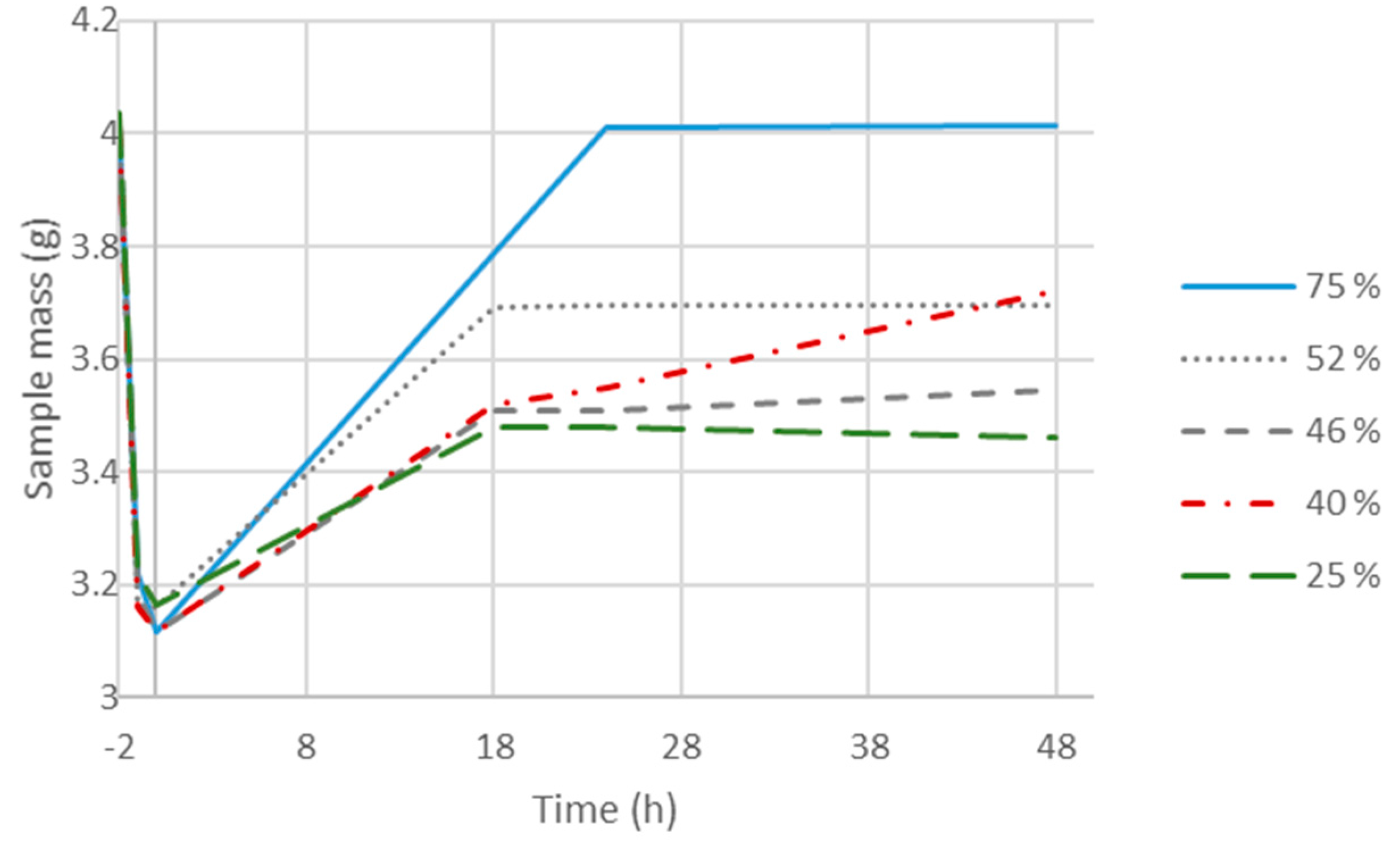
Shown in Figure 7, the hydration time is not significantly affected by the lower RH, considering the hydration levels reached after 18 h are close to, or similar to the final value of mass increase. However, in the test with 40% RH, a mass increase from 0.14 to 0.19 g/gsample was obtained between 24 and 48 h. This indicates that the kinetics of the TES system will not be compromised while operating at lower RH, as a large fraction of the hydration is possible with at lower RH in reasonable time. In case of day/night heat storage, several days of hydration may take place, considering that cloudy or stormy days may give much lower amounts of solar heat.
4.2. Heat Storage Efficiency and Operational Opportunities
As mentioned in Section 2.1.1, the RH of the air reaches levels up to 36% when pumped from the evaporator at 5 °C (the temperature of the ground) if no overpressure is applied. By pressuring the evaporator according to Figure 1, a higher RH can be obtained in the reactor. The increased RH and absolute humidity (AH) of pressuring (pevaporator) the evaporator are shown in Table 2 [25]. Dew point, hydration results and heat storage capacity, with the assumption of both component was hydrated equally are also shown in Table 2.
The result of 0.093 g/gsample mass increase with 25% RH, showing that with the evaporation temperature of 0 °C, it is possible to hydrate to approximately a third of the maximum value obtained. Requiring no overpressure and a water vapour amount similar to 70% RH at 5 °C, less use of the evaporator is needed for the first third of hydration in the reactor section operated. This indicates a high efficiency for the system. The hydration result of 0.14–0.19 g/gsample, which equals between half and two thirds of the best hydration result at 40–52% RH, would require pressure between 1.1 and 1.4 bar, requiring a small amount of electricity. However, for the last part of the hydration, a pressure of 2 bar is required in the evaporator to obtain the 75% RH that gives the best hydration results, indicating that the COP of the system would be lower compared to operating at lower pressures.
A reactor design with several sections gives the opportunity to switch between phases in the reactor, for optimal operation. Moreover, this gives an opportunity to regulate the electrical efficiency (or COP) of the system coupled and regulated by smart grid systems. During high electricity demand, a lower pressure (higher COP) in the evaporator can be applied, and during relatively lower electricity demand, higher pressure (lower COP) can be applied, which preferably could be operated or integrated with smart grids.
4.3. Sample Morphology, Crystal and Efficiency
According to others, NQ are needle shaped crystals (e.g., Figure 3a) and hydromagnesite (HM) is irregular flakes that in (e.g., partly in Figure 3b), which makes it of interest to analyse the crystals’ appearance using SEM pictures [21,22].
Shown in Figure 8, Sample 2 has HM flakes and some undamaged NQ, besides agglomerated or partly reacted NQ, which can be compared with re-hydrated NQ by others [21]. Sample 1 (shown in Figure 3b) seems to have more HM crystal flakes, which can be a reason for its smaller hydration capacity. Moreover, in Sample 1 the NQ needles are agglomerated in a more compact shape compared to Sample 2, which could explain the lower reactivity.
4.4. Efficiency Calculations and Improvements
The COP of the TES system (COPTES) was calculated as the total heat output Qtot (including the excess heat from the compressor train and the reactor heat output) divided by the electricity required for the compressor according to Equation (1).
Other losses (e.g., heat exchange) in the system were neglected, as minimising the efficiency penalty of compressing gas for water vapour generation is the major challenge. Overall compressor and turbine efficiency of 0.88 were chosen for the calculations although these efficiencies depend on several factors (flow coefficients and device quality to name a few) [26].
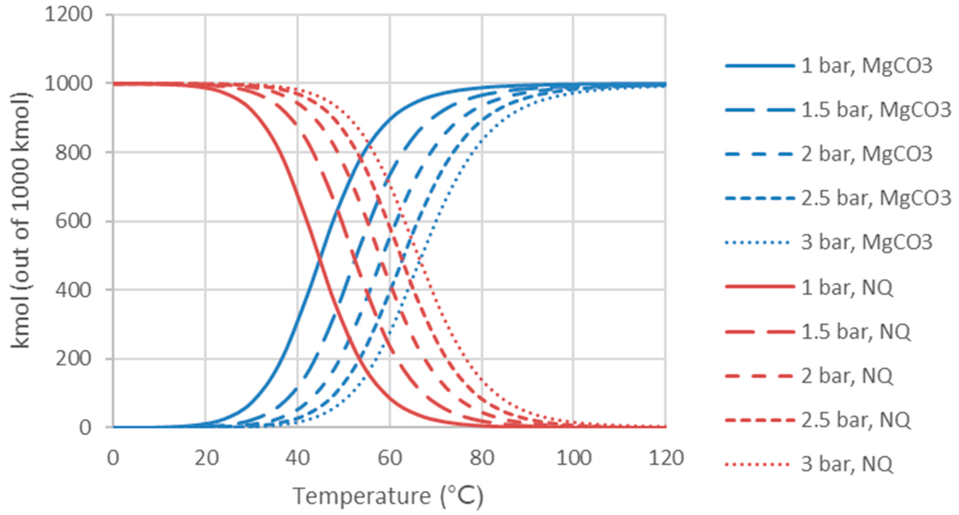
The work required for the generation of water vapour, according to Figure 1, would approximately give a COPTES of 2–4 depending on whether a pressure of 1.41 or 2 bar is used in the evaporator and the reactor, as shown in Table 3. However, the COPTES can be improved by two different methods. Firstly, increasing the total pressure in the system, giving a larger absolute humidity, decreases the amount (mass) of compressed gas per mass water vapour [25]. Increasing the reactor pressure to 2 bar gave a slightly better hydration test result of 0.293 g/gsample mass increase, giving a storage capacity of 0.49 MJ/kg, as shown in Table 2. Figure 9 shows that at a higher pressure both the dehydration and hydration reactions will take place at slightly higher temperature, according to Gibbs free energy calculations. Secondly, coupling two circuits in series, decreasing the temperature difference in each individual circuit, leads to decreased requirements for water vapour generation at lower temperatures according to the results shown in Table 3. A smaller temperature difference between the evaporator and the reactor requires a lower pressure in the evaporator for a certain RH in the reactor and requires less compressor work.
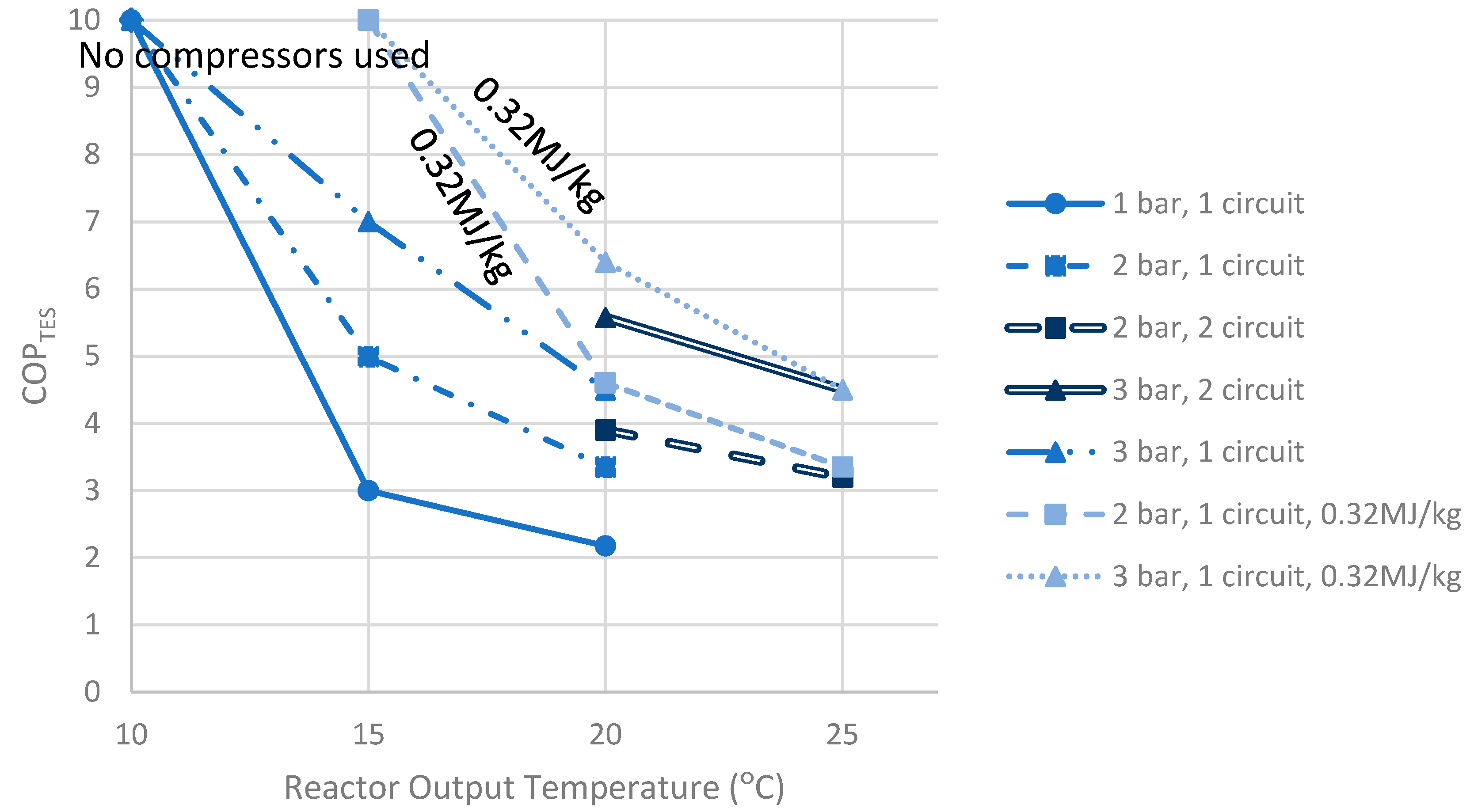
In Figure 10, an improved concept of the system with two circuits is shown. Assuming similar chemical reaction behaviour of the material at 15 °C and 25 °C, two circuits in series would improve the COP when maximum heat storage capacity is achieved (when a higher RH is used in the reactor). As shown in Table 3, this gives a COPTES of about 7 in the first circuit with 5 °C in the bubble column (located underground) and 15 °C in the reactor, or a COPTES as high as about 11 in the second circuit with 15 °C in the bubble column and 25 °C in the reactor. It gives a COPTES average of 4.5, when the reactor pressure is 3 bar and evaporator 4.32 bar. Shown in Figure 11, approaching 20 °C temperature in the similar case, the COP would be 5.6. A 5 °C higher end temperature would decrease the temperature rise to be realised by the heat pump. However, this COPTES value is only valid when the reaction is reaching full hydration and maximum heat storage is used, being larger when a lower RH is used. The single circuit system had a COPTES of 4.6, with a reactor operated at 3 bar, while approaching 20 °C, and with lower RH (55%), giving a storage capacity of 0.32MJ/kg, the COPTES is 6.4.
This gives an interesting optimisation challenge, depending on whether using two circuits or using less compression (giving only 0.32 MJ/kg and improved COPTES).
4.5. Output of Reactor Coupled with Exhaust Air Heat Pump (EAHP)
Two tests were done without CO2, in the hydration phase, at operation temperature 8–11 °C according to the process scheme in Figure 4, and at 20 °C for comparison with the test done with 3%-vol CO2. Shown in Table 4, the mass increase at operation temparture is 0.214 g/gsample, giving a calculated heat storage capacity of 0.36 MJ/kg. However, at 20 °C and 95% RH a mass increas of 0.422 g/gsample was achieved, giving a calculated heat storage capacity of 0.70 MJ/kg, which is slighly larger than 0.41 g/gsample at 75% and 3%-vol CO2 shown in Figure 6. This suggest that the CO2 amount and RH above 75% does not affect the hydration significantly. However, the lower operation tempreature of 8–11 °C, with about 2.5 times lower absolute humidity, results in half hydration conversion. The reaction kinetics seems not be affected by the lower reaction temperature in earlier studies (compared to 20 °C), releasing about 70% of the energy storage capacity during 24 h.
The heat effect of the TES reactor giving a temperature increase depending on the water vapour available are shown in Figure 12. The heat output of the TES would be 22–32% of the EAHP, depending on the RH of the indoor air. In the calculations, the RH of the output air from the reactor is 25% at the temperature of 4 °C (output temperature from EAHP) + ΔT, temperature increase (in the reactor).
4.6. Silica Gel/Nesquehonite Mass Ratio
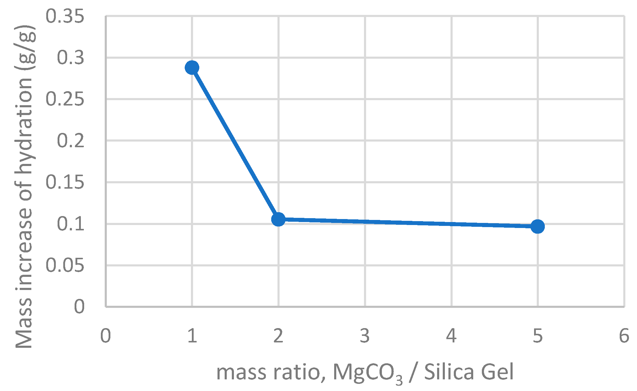
Considering that NQ has a better heat storage capacity (per volume) and would be a less expensive resource than SG, testing hydration performance on mixtures with higher amounts NQ per SG was done aiming at lower material costs. Figure 13 shows that the double amount of NQ per SG (4 g per 2 g) will decrease the hydration to a 0.105 g/gsample mass increase, which is not sufficient. The result is very close to the hydration of 0.096 g/gsample with the mass ratio of 5 NQ per SG (5 g per 1 g). This indicates that if SG contact with air is compromised, the mass increase of hydration is close to 0.1 g/g, and the optimal mixture is between 1 and 2 NQ per SG (1–2 g/g).
5. Conclusions
A thermal energy storage (TES) system using mixed nesquehonite (NQ) and silica gel (SG) can use both low (25–50%) and high (75%) relative humidity (RH) air for hydration. The hydration at 40% RH gives a thermal storage capacity of 0.32 MJ/kg and at 75% RH gives a capacity of 0.68 MJ/kg. Therefore, the system can initially work at lower RH, which is more energy efficient, and later at higher RH to complete the hydration.
Sufficient levels of coefficient of performance for the thermal energy storage system can be achieved with:
- -
- increased absolute humidity by operating the hydration reactor at slightly elevated pressure.
- -
- using a two (instead of one) circuit system decreasing the temperature difference in the system, decreasing the pressure difference between the evaporator and reactor.
- -
- sufficiently high compressor and turbine efficiency.
- -
- exhaust air heat pump (EAHP) chilled outlet air, with high RH, eliminating the compressor reqirement.
The kinetics of the TES system are not compromised when operating at lower RH, as a large fraction of the hydration is possible with at lower RH in reasonable time. When combining the TES reactor with EAHP, the additional heat output of the TES is 22–32% of the EAHP. The optimal weight ratio between dehydrated NQ and SG is between 1 and 2 MgCO3/SG.
Acknowledgments
The authors want to acknowledge Fortum Foundation, K.V. Lindholms Stiftelse and Erkki Paasikivi Foundation, for financial support for this work.
Author Contributions
Rickard Erlund and Ron Zevenhoven together developed the concept of TES using hydrated magnesite into an experimental assessment supported by model calculations. Rickard Erlund carried out the experimental work, produced the first designs of the process schemes presented and wrote the first draft of the paper.
Conflicts of Interest
The authors declare no conflict of interest.
Abbreviations
| AH | Absolute humidity |
| COP | Coefficient of performance |
| COPTES | Coefficient of performance for the TES system |
| EAHP | Exhaust air heat pump |
| HM | Hydromagnesite |
| NQ | Nesquehonite |
| pevaprator | Pressure in the evaporator/bubble column |
| preactor | Pressure in the adsorption reactor |
| Qtot | Total heat effect of the TES system, including heat from the reactor and waste heat from compressor work |
| RH | Relative humidity |
| SEM | Scanning electron microscope |
| SG | Silica gel |
| TES | Thermal energy storage |
| Tevaporator | Temperature in the evaporator/bubble column |
| Treactor | Temperature in the adsorption reactor |
References
- Edem N’Tsoukpoe, K.; Liu, H.; Le Pierrès, N.; Luo, L. A review on long-term sorption solar energy storage. Renew. Sustain. Energy Rev. 2009, 13, 2385–2396. [Google Scholar] [CrossRef]
- Bauer, D.; Marx, R.; Nußbicker-Lux, J.; Ochs, F.; Heidemann, W.; Müller-Steinhagen, H. German central solar heating plants with seasonal heat storage. Sol. Energy 2010, 84, 612–623. [Google Scholar] [CrossRef]
- Whiting, G.; Grondin, D.M.; Bennici, S.; Auroux, A. Heats of water sorption studies on zeolite–MgSO4 composites as potential thermochemical heat storage materials. Sol. Energy Mater. Sol. Cells 2013, 112, 112–119. [Google Scholar] [CrossRef]
- Hongois, S.; Kuznik, F.; Stevens, P.; Roux, J.-J. Development and characterization of a new MgSO4-zeolite composite for long-term thermal energy storage. Sol. Energy Mater. Sol. Cells 2011, 95, 1831–1837. [Google Scholar] [CrossRef]
- Zondag, H.; Kikkert, B.; Smeding, S.; de Boer, R.; Bakker, M. Prototype thermochemical heat storage with open reactor system. Appl. Energy 2013, 109, 360–365. [Google Scholar] [CrossRef]
- HSC Chemistry, version 8.1.1; Reaction Equations; Outotec: Pori, Finland, 2014.
- Hill, R.J.; Canterford, J.H.; Moyle, F.J. New data for lansfordite. Miner. Soc. 1982, 46, 453–457. [Google Scholar] [CrossRef]
- Zevenhoven, R.; Slotte, M.; Åbacka, J.; Highfield, J. A comparison of CO2 mineral carbonation processes involving a dry or wet carbonation step. Energy 2016, 177, 604–611. [Google Scholar] [CrossRef]
- Zevenhoven, R.; Slotte, M.; Koivisto, E.; Erlund, R. Serpentine carbonation process routs using ammonium sulphate and integration in industry. Energy Technol. 2017, 5, 945–954. [Google Scholar] [CrossRef]
- Koivisto, E.; Erlund, R.; Zevenhoven, R. Extraction of magnesium from four Finnish magnesium silicate rocks for CO2 mineralisation—Part 1: Thermal solid/solid extraction. Hydrometallurgy 2016, 166, 222–228. [Google Scholar] [CrossRef]
- Erlund, R.; Koivisto, E.; Zevenhoven, R. Extraction of magnesium from four Finnish magnesium silicate rocks for CO2 mineralisation—Part 2: Aqueous solution extraction. Hydrometallurgy 2016, 166, 229–236. [Google Scholar] [CrossRef]
- Morgan, B.; Wilson, S.; Madsen, I.; Gozukara, J. Increased thermal stability of nesquehonite (MgCO3·H2O) in the presence of humidity and CO2: Implications for low-temperature CO2 storage. Int. J. Greenh. Gas Control 2015, 39, 366–376. [Google Scholar] [CrossRef]
- Erlund, R.; Zevenhoven, R. Thermal storage of (solar) energy by sorption of water in magnesium (hydro) carbonates. Int. J. Thermodyn. 2017, 20, 102–109. [Google Scholar] [CrossRef]
- Hollingbery, L.A.; Hull, T.R. The fire retardant behaviour of huntite and hydromagnesite—A review. Polym. Degrad. Stabil. 2010, 95, 2213–2225. [Google Scholar] [CrossRef]
- Tahat, M.A. Heat-pump/energy-store using silica gel and water as a working pair. Appl. Energy 2001, 69, 19–27. [Google Scholar] [CrossRef]
- Lim, K.; Che, J.; Lee, J. Experimental study on adsorption characteristics of a water and silica-gel based thermal energy storage (TES) system. Appl. Therm. Eng. 2017, 110, 80–88. [Google Scholar] [CrossRef]
- Statens Energimyndigheten, Sweden. Available online: http://www.energimyndigheten.se/tester/tester-a-o/bergvarmepumpar/bergvarmepumpar/ (accessed on 5 December 2017). (In Swedish).
- Johannes, K.; Kuznik, F.; Hubert, J.-L.; Durier, F.; Obrecht, C. Design and characterisation of a high powered energy dense zeolite thermal energy storage system for buildings. Appl. Energy 2015, 159, 80–86. [Google Scholar] [CrossRef]
- Aydin, D.; Casey, S.P.; Riffat, S. The latest advancements on thermochemical heat storage systems. Renew. Sustain. Energy Rev. 2015, 41, 356–367. [Google Scholar] [CrossRef]
- Jauffret, G.; Morrison, J.; Glasser, F.P. On the thermal decomposition of nesquehonite. J. Therm. Anal. Calorim. 2015, 122, 601–609. [Google Scholar] [CrossRef]
- Morrison, J.; Jauffret, G.; Galvez-Martos, J.K.; Glasser, F.P. Magnesium-based cements for CO2 capture and utilization. Cem. Concr. Res. 2016, 85, 183–191. [Google Scholar] [CrossRef]
- Teir, T.; Kuusik, R.; Fogelholm, C-J.; Zevenhoven, R. Production of magnesium carbonates from serpentinite for long-term storage of CO2. Int. J. Miner. Process. 2007, 85, 1–15. [Google Scholar] [CrossRef]
- Fracastoro, G.V.; Serraino, M. Energy analyses of buildings equipped with exhaust air heat pumps (EAHP). Energy Build. 2010, 42, 1283–1289. [Google Scholar] [CrossRef]
- Mikola, A.; Kõiv, T-A. The Efficiency Analysis of the Exhaust Air Heat Pump System. Engineering 2014, 6, 1037–1045. [Google Scholar] [CrossRef]
- Ren, H.-S. Construction of a generalized psychrometric chart for different pressures. Int. J. Mech. Eng. Educ. 2004, 32, 212–222. [Google Scholar] [CrossRef]
- How to Estimate Compressor Efficiency? Available online: http://www.jmcampbell.com/tip-of-the-month/2015/07/how-to-estimate-compressor-efficiency/ (accessed on 5 December 2017).
Figure 1.
Scheme of the process coupled with a heating system. C = Compressor, T = Turbine.
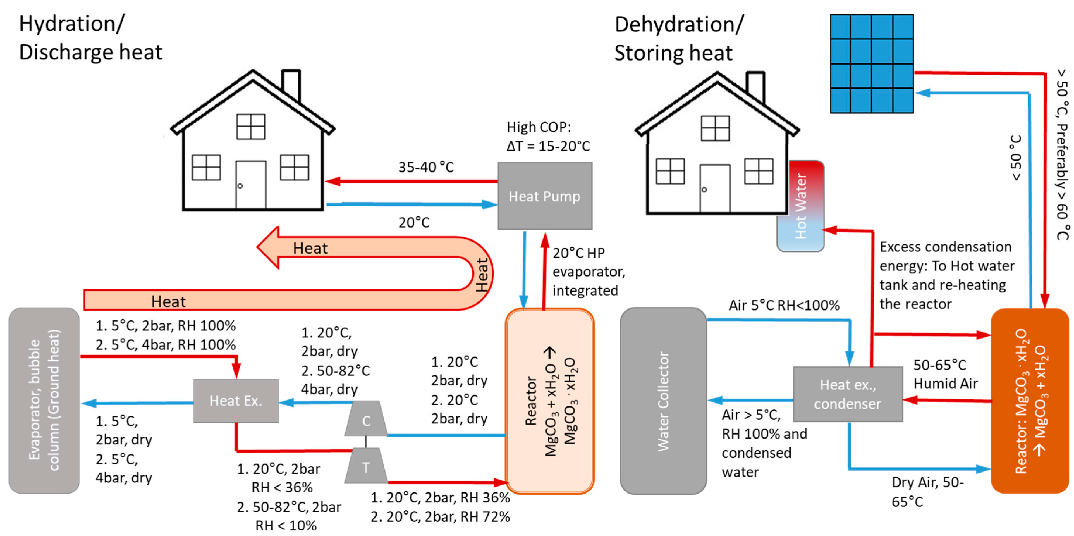
Figure 2.
Dehydration conversion results after 120 min and theoretical conversion calculated using Gibbs free energy minimisation software [13].
Figure 2.
Dehydration conversion results after 120 min and theoretical conversion calculated using Gibbs free energy minimisation software [13].

Figure 3.
Left (a) NQ stored 2 month in air, Right (b) NQ twenty times dehydrated and re-hydrated.
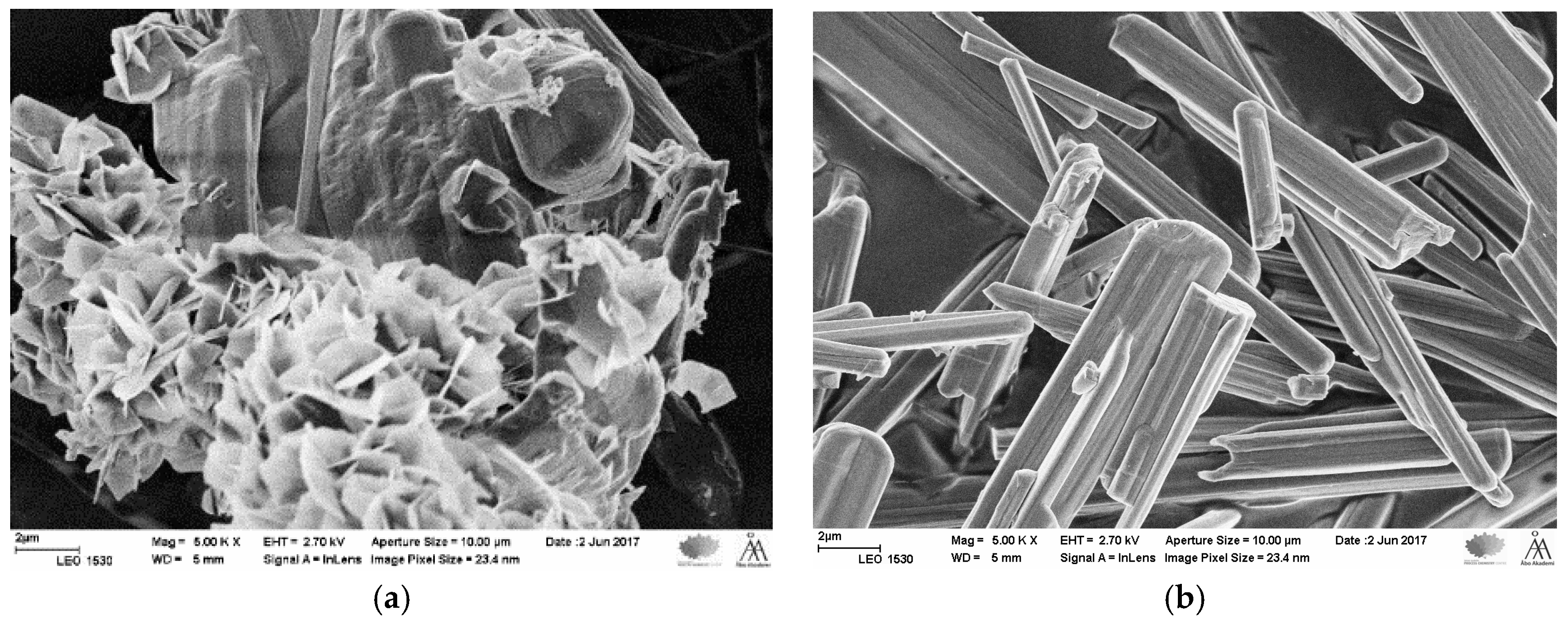
Figure 4.
Scheme of the thermal energy storage reactor combined with an auxiliary heat pump.

Figure 5.
Mass increase of hydration versus relative humidity (RH) of 50%-wt/50%-wt silica gel and dehydrated NQ, and pure silica gel for reference. (Experiment duration 48 h).
Figure 5.
Mass increase of hydration versus relative humidity (RH) of 50%-wt/50%-wt silica gel and dehydrated NQ, and pure silica gel for reference. (Experiment duration 48 h).

Figure 6.
Mass increase of hydration and TES capacity versus relative humidity (RH) and evaporator pressure for 50%-wt/50%-wt silica gel and dehydrated NQ, and pure silica gel for reference (Experiment duration 48 h).
Figure 6.
Mass increase of hydration and TES capacity versus relative humidity (RH) and evaporator pressure for 50%-wt/50%-wt silica gel and dehydrated NQ, and pure silica gel for reference (Experiment duration 48 h).

Figure 7.
Mass difference on the NQ+SG granule mixture sample, during dehydration (−2 to 0 h) and hydration (0 to 48 h).
Figure 7.
Mass difference on the NQ+SG granule mixture sample, during dehydration (−2 to 0 h) and hydration (0 to 48 h).

Figure 8.
SEM pictures of Sample 2: (a) 1000× and (b) 5000×.

Figure 9.
Gibbs energy minimization of reaction MgCO3 + 3H2O = MgCO3∙3H2O for various pressures.

Figure 10.
Scheme of the hydration step with two circuits in the thermal energy storage process. The dotted lines stands for the compressor, turbine and heat exchanger similar system shown in Figure 1. The reactor is at 15 °C. Evaporator 2 is integrated with Reactor 1 to minimise the temperature difference.

Figure 11.
COP calculations with relative humidity 75% in the reactor and 5°C in the evaporator, various reactor temperature. The COPTES values of 10 are approximate as no compressors are used, and only fans will be used. Compressor/turbine efficiency: η = 0.88.
Figure 11.
COP calculations with relative humidity 75% in the reactor and 5°C in the evaporator, various reactor temperature. The COPTES values of 10 are approximate as no compressors are used, and only fans will be used. Compressor/turbine efficiency: η = 0.88.

Figure 12.
The heat recovered using EAHP and with compressor work added, giving EHAP total heat output in grey. The COP of the EAHP used for the calculations is 3.4, which is an experimental value presented by others [24]. Shown in orange, is the TES heat output and the temperature increase in the reactor showed.
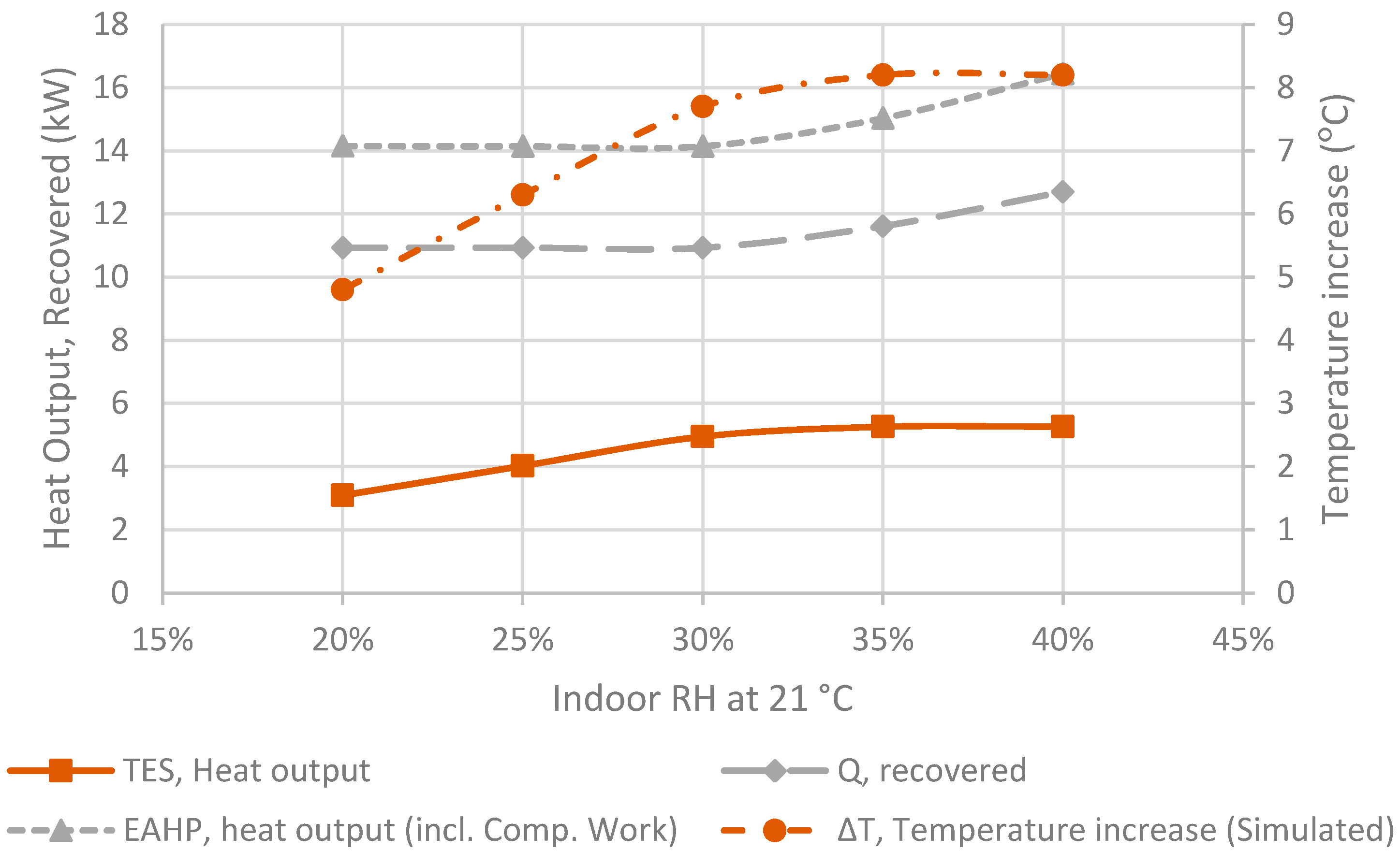
Figure 13.
The mass ratio of dehydrated NQ in form of MgCO3 per SG in granules 3–6 mm versus hydration in form of mass increase after the reaction was stabilised at 24 h.
Figure 13.
The mass ratio of dehydrated NQ in form of MgCO3 per SG in granules 3–6 mm versus hydration in form of mass increase after the reaction was stabilised at 24 h.


Table 1.
Operational temperatures and theoretical specific heat storage capacity of potential sorption reactions.
Table 1.
Operational temperatures and theoretical specific heat storage capacity of potential sorption reactions.
| Reaction | Hydration Temp. (°C) | T (ΔG = 0) (°C) | 90% Dehydr. (°C) | Dehydr. Temp. (°C) | Specific Capacity (MJ/kg) |
|---|---|---|---|---|---|
| MgCO3 + 3H2O(g) = MgCO3·3H2O | ~20 | 45 | 61 | 60–65 | 1.0 |
| MgCO3 + xH2O(l) = MgCO3· xH2O | Irrev. | Irrev. | |||
| MgCO3 + 5H2O(g) = MgCO3·5H2O | 5–10 | 55 | 66 | 65–70 | 1.41 |
| MgSO4 + 7H2O(g) = MgSO4·7H2O | ~20 | 145 | 153 | 122 1) | 1.7 |
| 2H2O (20 °C) = 2H2O (60 °C) | 20 2) | - | - | 60 2) | 0.17 |
| Silica gel | ~20 | - | 65 3) | 100 | 0.62 |
| (Silica gel dehydrated at 65 °C) | ~20 | - | - | 65 | 0.52 |
| Zeolite HY [4] | ~20 | - | ~110 | 110 | 0.8 |
| Zeolite Na-Y (dehydrated) = Zeolite Na-Y (hydrated) [4] | ~20 | - | ~140 | 140 | 1.0 |
| MgCl2·6H2O = MgCl2·2H2O + 4H2O [5] | 60 | 100 | - | 150 |
1) Partly dehydrates at 122 °C [3]. 2) The required operating temperatures for using water as latent heat storage with a ΔT of 40 °C. 3) 85% dehydrated, matched to NQ hydration temperature.
Table 2.
Data on the relation between the humidity and pressure in the evaporator, and storage capacity and hydration results after 48 h. The humid hydration gas contains 3% CO2.
Table 2.
Data on the relation between the humidity and pressure in the evaporator, and storage capacity and hydration results after 48 h. The humid hydration gas contains 3% CO2.
| Relative Humidity in Reactor | Hydration Mass Increase (g/gsample) | TDewpoint at 1 bar (°C) | pevaporator for 100% RH (bar) | Absolute Humidity (g/kg) | Specific Capacity (MJ/kg) | Sample Nr. |
|---|---|---|---|---|---|---|
| 25% | 0.093 | 0 | 0.7 | 3.7 | 0.16 | 1 |
| 36% | - | 5 | 1 | 5.3 | - | |
| 40% | 0.194 | 7 | 1.1 | 6.3 | 0.32 | 1 |
| 46% | 0.138 | 8 | 1.2 | 6.7 | 0.23 | 1 |
| 52% | 0.169 | 10 | 1.4 | 7.7 | 0.28 | 1 |
| 75% | 0.288 | 15 | 2 | 11.0 | 0.48 | 1 |
| 75% | 0.253 | 15 | 2 | 11.0 | 0.42 | 1 |
| 75% | 0.293 | 15 | 4 * | 22.0 | 0.49 | 1 |
| 75–80% | 0.410 ** | 14 | 2 | 11.0 | 0.68 | 2 |
* The pressure in the reactor is 2 bar. ** Reaction completed after 6 days.
Table 3.
The COPTES depending on pressure and temperature in both the evaporator and reactor, number of circuits and compressor/turbine efficiency. One system circuit is calculated according to process scheme in Figure 1 and two circuit system calculated according to process scheme in Figure 10.
| Tevaporator (°C) | pevaprator (bar) | Treactor (°C) | preactor (bar) | Relative Humidity, Reactor (%) | Storage Capacity (MJ/kg) | COPTES | System Circuits |
|---|---|---|---|---|---|---|---|
| 5 | 2 | 20 | 1 | 75% | 0.48 | 2.2 | 1 |
| 5 | 1.41 | 20 | 1 | 55% | 0.32 | 2.8 | 1 |
| 5 | 1 | 20 | 1 | 36% | 0.22 | No Comp. | 1 |
| 5 | 1.41 | 15 | 1 | 75% | 0.48 1) | 3.0 | 2 |
| 15 | 1.41 | 25 | 1 | 75% | 0.48 1) | 4.3 | 2 |
| 5 | 4 | 20 | 2 | 75% | 0.49 | 3.3 | 1 |
| 5 | 2.82 | 20 | 2 | 55% | 0.32 | 4.6 | 1 |
| 5 | 4.32 | 20 | 3 | 55% | 0.32 | 6.4 | 1 |
| 5 | 4.32 | 15 | 3 | 75% | 0.49 3) | 7.0 (4.5) 2) | 2 |
| 15 | 4.32 | 25 | 3 | 75% | 0.49 3) | 11 (4.5) 2) | 2 |
| 5 | 6 | 20 | 3 | 75% | 0.49 3) | 4.5 | 1 |
1) Assuming that storage capacity is similar to test done at 20 °C. 2) Total COPTES of a two-step process. 3) Assuming the capacity is similar to reaction at 2 bar.
Table 4.
Data on test without CO2 using sample 2, according to the process scheme in Figure 4.
Table 4.
Data on test without CO2 using sample 2, according to the process scheme in Figure 4.
| Relative Humidity in Reactor | Hydration Mass Increase (g/gsample) | Temperature (°C) | Reactions Time until Stagnation | Absolute Humidity (g/kg) | Specific Capacity (MJ/kg) | Sample Nr. |
|---|---|---|---|---|---|---|
| 65–75% | 0.214 | 8–11 | 4 days | 0.053 | 0.36 | 2 |
| 95% | 0.422 | 20 | 2 weeks | 0.14 | 0.70 | 2 |
© 2018 by the authors. Licensee MDPI, Basel, Switzerland. This article is an open access article distributed under the terms and conditions of the Creative Commons Attribution (CC BY) license (http://creativecommons.org/licenses/by/4.0/).
Share and Cite
MDPI and ACS Style
Erlund, R.; Zevenhoven, R. Hydration of Magnesium Carbonate in a Thermal Energy Storage Process and Its Heating Application Design. Energies 2018, 11, 170. https://doi.org/10.3390/en11010170
AMA Style
Erlund R, Zevenhoven R. Hydration of Magnesium Carbonate in a Thermal Energy Storage Process and Its Heating Application Design. Energies. 2018; 11(1):170. https://doi.org/10.3390/en11010170
Chicago/Turabian StyleErlund, Rickard, and Ron Zevenhoven. 2018. "Hydration of Magnesium Carbonate in a Thermal Energy Storage Process and Its Heating Application Design" Energies 11, no. 1: 170. https://doi.org/10.3390/en11010170
Note that from the first issue of 2016, this journal uses article numbers instead of page numbers. See further details here.