Optimization and Practice of Support Working Resistance in Fully-Mechanized Top Coal Caving in Shallow Thick Seam

1
State Key Laboratory for Geomechanics and Deep Underground Engineering, China University of Mining and Technology, Xuzhou 221116, China
2
Western Australia School of Mines, Curtin University, Kalgoorlie, WA 6430, Australia
*
Author to whom correspondence should be addressed.
Energies 2017, 10(9), 1406; https://doi.org/10.3390/en10091406
Submission received: 20 August 2017
/
Revised: 4 September 2017
/
Accepted: 12 September 2017
/
Published: 14 September 2017
Abstract
:Based on the overburdened structure of shallow coal seams in the West of China, the traditional support resistance method may not apply in such regions due to many roof shear and support crushing accidents. Four support working resistance indexes—rated working resistance, average working resistance, average-partial working resistance, and average-upper working resistance are counted as the candidate working resistance. The method of optimizing and inverting working resistance was put forward based on the roof control effect and working resistance overrun percentage. The simulation of a fully-mechanized top coal caving working face was built by using the UDEC software to analyze the top coal cavability and roof subsidence under different supporting strengths to determine the final working resistance. The project practice of 1322 working face in Jindi coal mine shows that the working resistance is 80–90% of calculated rated working resistance. The hydraulic support is worked under good condition. There is no pillar shrinkage and support crushing during coal mining.
1. Introduction
Half of the world’s coal reserve is thick coal seam [1,2,3]. Mining methods in Poland, Hungary, former Yugoslavia, France, India, and China are generally similar. Differences arise due to local conditions [4,5,6,7,8]. The top coal caving method was first applied in the 1940s in Russia and then subsequently used in France, former Yugoslavia, Hungary, Romania, former Czechoslovakia, and Turkey [9]. This method has been in use in China and India since the 1980s [7,10]. At present, in China, higher coal production is gradually being shifted towards the western region [11] where the coal seams are thick with shallow depth and special overburden structure [12,13]. Fully-mechanized top caving mining is widely applied in those geological conditions.
Due to substantial mining height, special overburden structure, and the shallow depth coal seams, many problems have been encountered in the top coal mining working face, such as roof shearting (roof fall), support crushing, and threatened safety of the working face [14,15,16,17,18,19]. For example, in Ciliugou fully-mechanized caving face where the support working resistance was 15,000 kN, a roof shear accident occurred which led to the crushing of the hydraulic support. With the Cuimu mine site’s fully-mechanized caving face, which had a support working resistance of 10,500 kN, strong pressure was observed frequently which affects the safety of the working face [20,21,22]. Many researchers analyzed the reason for the roof shear accidents and hydraulic support crushing. Xu [23], Zhang [24], Yi [25], and Yan [26] all proposed that the crushing of the hydraulic supports resulted in roof shear mainly due to the lower rated working resistance. So, reasonable support working resistance is essential to guarantee working safety during mining and to save the cost of hydraulic support.
Many research works about the working resistance calculation in top caving working face have been done. Zhang [27] and He [28] analyzed the overburden movement character in the top caving working face, which is an important factor to calculate the hydraulic support working resistance. Singh and Singh [29] monitored strata control parameters and behavior of a powered support in a mechanized longwall caving face. Singh [30] also developed design criteria for selection of optimal capacity support integrating the field experience. Su [31] and Chen [32] developed a formula to calculate the support resistance in longwall mines. Wang [33] researched support working resistance of fully-mechanized caving in steeply dipping ultra-thick seams based on physical simulation tests. Yu [34] developed the analytic expression of support working resistance with top coal caving in extra thick coal seam by analyzing the immediate roof and main roof subsidence. Kong [35] studied the reasonable working resistance of hydraulic support by using microseismic monitoring technology, similar material simulation test. However, those working resistance calculation methods did not consider shallow depth coal seams where the support resistance may not be applicable.
In this paper, a design flow to calculate the support resistance in the fully-mechanized top coal caving working face is proposed by considering the overburden movement characteristic, using statistics and verifying with field practice. The top coal caving property and roof subsidence in different supporting intensities are also analyzed by using numerical simulation method to justify reasonable working resistance.
2. Engineering Background
2.1. General Situation of 1311 Caving Working Face
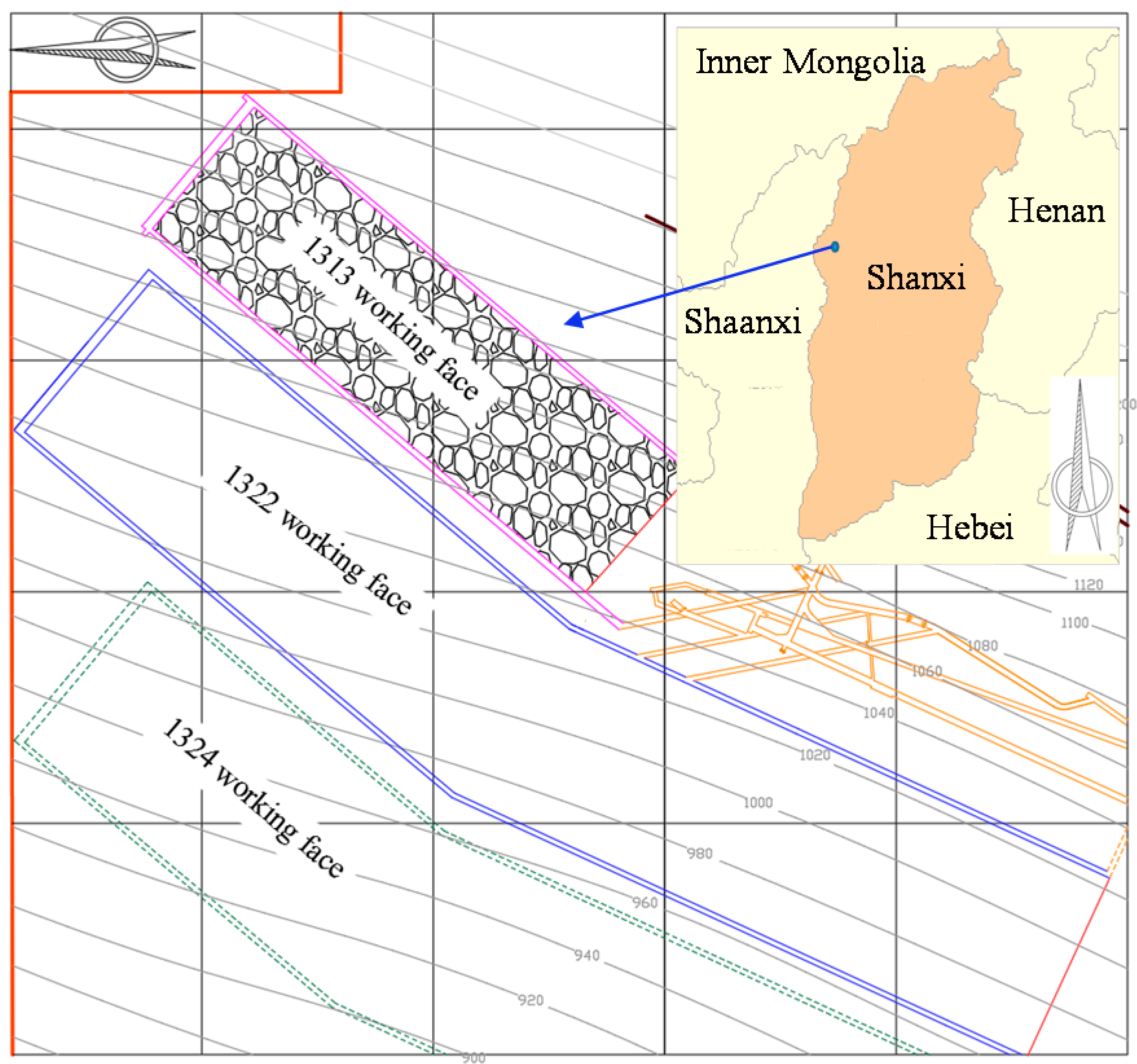
Jin Di coal mine is located in Gu Xian village, Xing Xian country, Shanxi province. This field, typical of loess plateau landform, belongs to the Lüliang mountains. The 1313 caving working face is to the west of 1322 working face. Its average length along the strike direction was 1050 m and the average width along the dip direction was 150 m. The working face layout is shown in Figure 1. The mining height is 3.2 m, the top coal height is 9.4 m. The fully-mechanized top coal caving method is used with top-cave hydraulic support model ZF8000/23/35.
2.2. General Situation of 1311 Caving Working Face
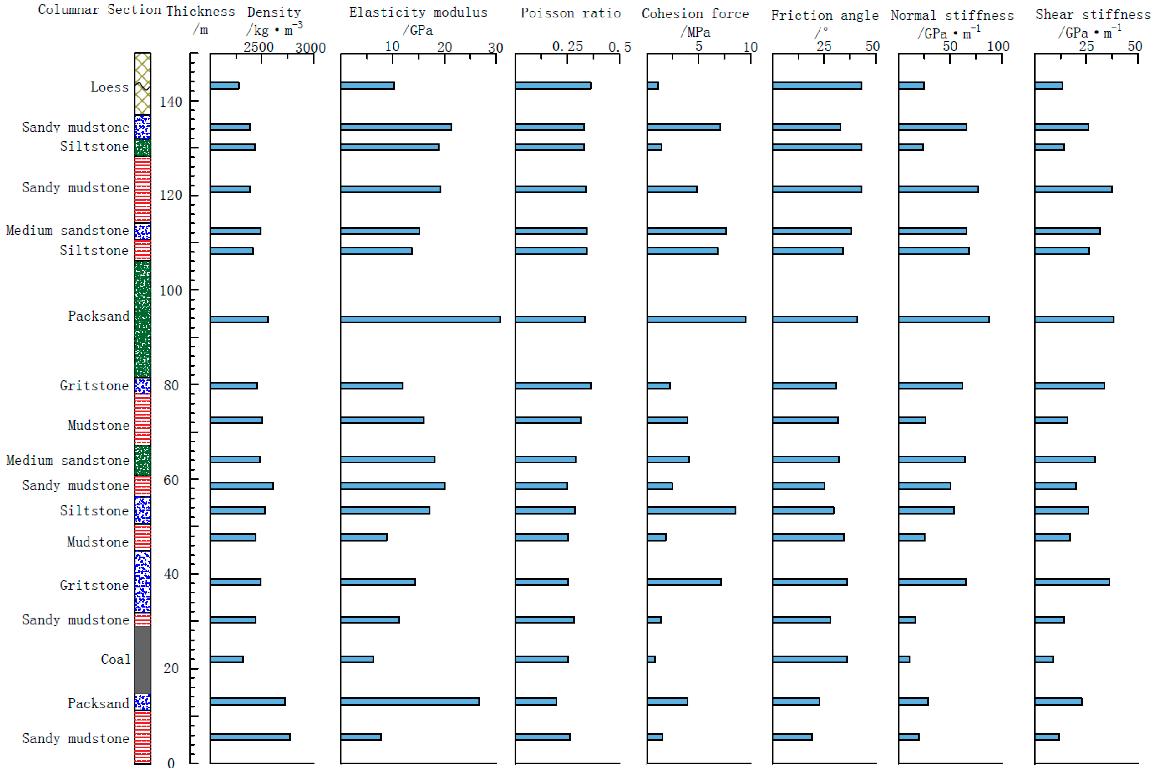
The panel mined is the no.13 coal seam, a lower middle segment of the Taiyuan group which has an average height of 12.6 m. The immediate roof above the panel consists of 3.5 m thick sandy mudstone and the main roof is gritstone, around 11 m thick, while the coal seam floor is packsand, 4.2 m. Rock strata core samples were collected above the panel 1311 and then the samples were tested in the laboratory for their mechanical properties. The bore hole columnar section and the rock strata basic mechanic propertyare shown in Figure 2.
2.3. Mine Pressure Behavior of 1311 Caving Working Face
The working resistance was monitored during the advancing working face. The end working resistance of the No. 25 support, located in upper dip direction of working face, and No. 60 support, located in the middle dip direction of working face, when advancing distance is from 568 m to 698 m were shown in Figure 3.
From the Figure 3, the support working resistance in middle area (No. 60 support) is larger than those on the sides (No. 25 support). The end working resistance of No. 60 support shows that pressure overruns for about 10 times and the longest overrun was obtained to continue for 8.7 m of the advancing distance. Meanwhile, the end working resistance of the No. 25 support shows that the pressure overrun happens only five times and in each case it continues for less than 3 m. The support in the whole working face is under full load working condition, which accounts 93.2–97.4% of rated working resistance and the average dynamic factor is 1.41. In addition, the average roof subsidence over the working face is 462 mm. In parts of the working face, roof subsidence is 2012 mm.
3. An Inversion Optimizing Method
3.1. Four Support Working Resistance
To analyze the stress monitored from the hydraulic support in a scientific way, the statistic method was adopted developed by Rausand and Arnljot [36]. The standard deviation was seen as a persuasive value in the statistical dispersion. Therefore, four working resistances-rated working resistance, average-partial working resistance, average-partial working resistance, average-upper working resistance were counted. One of them will be selected as the candidate working resistance.
- (1)
- Rated working resistance pThe rated working resistance is the maximum force that the hydraulic support exerts onto the roof.
- (2)
- Average working resistanceAverage working resistance is the average of the end working resistance during the roof weighting stage.where the end working resistance is , kN; the circulation number of roof weighting is n.
- (3)
- Average-partial working resistanceAverage-partial working resistance was defined as the sum of average working resistance and the mean square error.where the mean standard deviation is , kN.
- (4)
- Average-upper working resistance p2The average-upper working resistance is defined as the sum of average working resistance and the double mean square error.
According to the end working resistance of No. 25 and No. 60 support, those four support working resistance is calculated and shown in Figure 3.
3.2. The Partition of Roof Control Effect Level
The relationship of support and surrounding rock can be used by the following equation to express [37].
where the support strength is PT, MPa; the unit area of force from the roof to support is A, MPa; the state of constant is K, MPa; the maximum roof subsidence in working face is , mm; the roof subsidence in different working resistance is , mm.
Due to , where support area is S, Equation (5) can be transformed as
where the support resistance before the roof weighting is p0, kN, the roof state of constant is k, kN.
The maximum roof subsidence on the working face when the main roof is moved to the lowest state can be determined by the equation
where the mining height is h, m; the immediate roof height is Mz; m, the periodic roof weighting pace is c, m; the bulking coefficient of the immediate roof is KA; the maximum face width is LK, m.
So, the Equation (6) can be transformed as
3.3. Working Resistance Design Flow
Peng [38] pointed out that the roof subsidence cannot be too large during advancement of working face, which will influence mining work safety. When the safety valve is opened continuously, it will weaken the roof, which is bad for the key section of support strength. Even when the support is under a full working load, the roof is not under control, which crushes the support and effects working face safety. So, two very important reference indexes—roof control effect and working resistance overrun percentage—are selected to calculate the working resistance.
The reasonable working resistance calculate flow is shown as following: first, four working resistances are calculated and then its overrun percentage. If the percentage is less than 20%, then it can be chosen as the working resistance. Second, according to the roof subsidence Equation (8) in working face and the roof control level partition, shown in Table 1, if the roof control level partition is over the ‘Good’ value, then it can also be chosen as the working resistance. The specific working resistance design flow is shown in Figure 4.
3.4. Reasonable Working Resistance Calculation
According to the Equations (1)–(3), the Average working resistance , 7240 kN, average-partial working resistance , 7240 kN, average-upper working resistance p2, 8786 kN of six important support (No. 25, 50, 60, 70, 90, and 110) were calculated during working face advanced distance in 567–699 m. Following the design flow, the roof control level partition and overrun percentage, corresponding to the four working resistances, were obtained and shown in Table 2. Two overrun percentages are counted, one of which is the percentage of overrun value in statistic cycle number (n), A1, another of which is the percentage of overrun value in all cycle number (N), A2.
The three working resistance which are rated working resistance p, the Average working resistance , average-partial working resistance , were calculated for different hydraulic supports were calculated and were found to be in ‘Good’ range as shown in Table 2. The average overrun percentage was also found to be over 20%. It is difficult to support the roof when the roof weighing under those working resistance. The support column must be shrunk to support the roof. However, the roof control effect partial of average-upper working resistance p2 is ‘Good’ and there are no overrun performance. So the average-upper working resistance p2, 8786 kN, can be used as the 1313 working face resistance. The required working resistance (8786 kN) is higher than the applied working resistance (8000 kN) in 1313 working face which resulted in pillar shrinkage.
The 1322 caving working face and 1311 caving working face is adjacent working face. Considering the top coal cavability and roof subsidence, security coefficient, Section 2.1, was selected to calculate 1322 working face resistance. The working resistance and supporting strength of 1322 caving working face is designed as 10,000 kN and 1.21 MPa.
4. Top Coal Cavability and Roof Subsidence under Different Supporting Strengths
Top coal cavability is changed under different supporting strengths. It is an important factor that decides the success of caving mining [39]. Meanwhile, roof subsidence also is the key point that affects the safe mining and support health [40].
The simulation model of fully-mechanized top coal caving working face is built by using the UDEC software (Version 4.0, Itasca Consulting Group, Minneapolis, MN, USA) to analyze the top coal cavability and roof subsidence under different supporting strengths. The mechanical properties used for simulating the coal measures excavation are listed in Figure 1. In this conceptual model, the mechanical parameters of contacts were calibrated against common coal measures in the Jindi coal district, China. This was achieved by using the UDEC quadrangle logic for a consistent mesh pattern with in working face excavation model. The average edge length of these rectangular blocks in the coal seam area, immediate roof area and main roof area was 0.3, 0.15, and 1.5 m. The edge length of remainder rectangular blocks was 2 m.
4.1. Top Coal Cavability under Different Supporting Strength
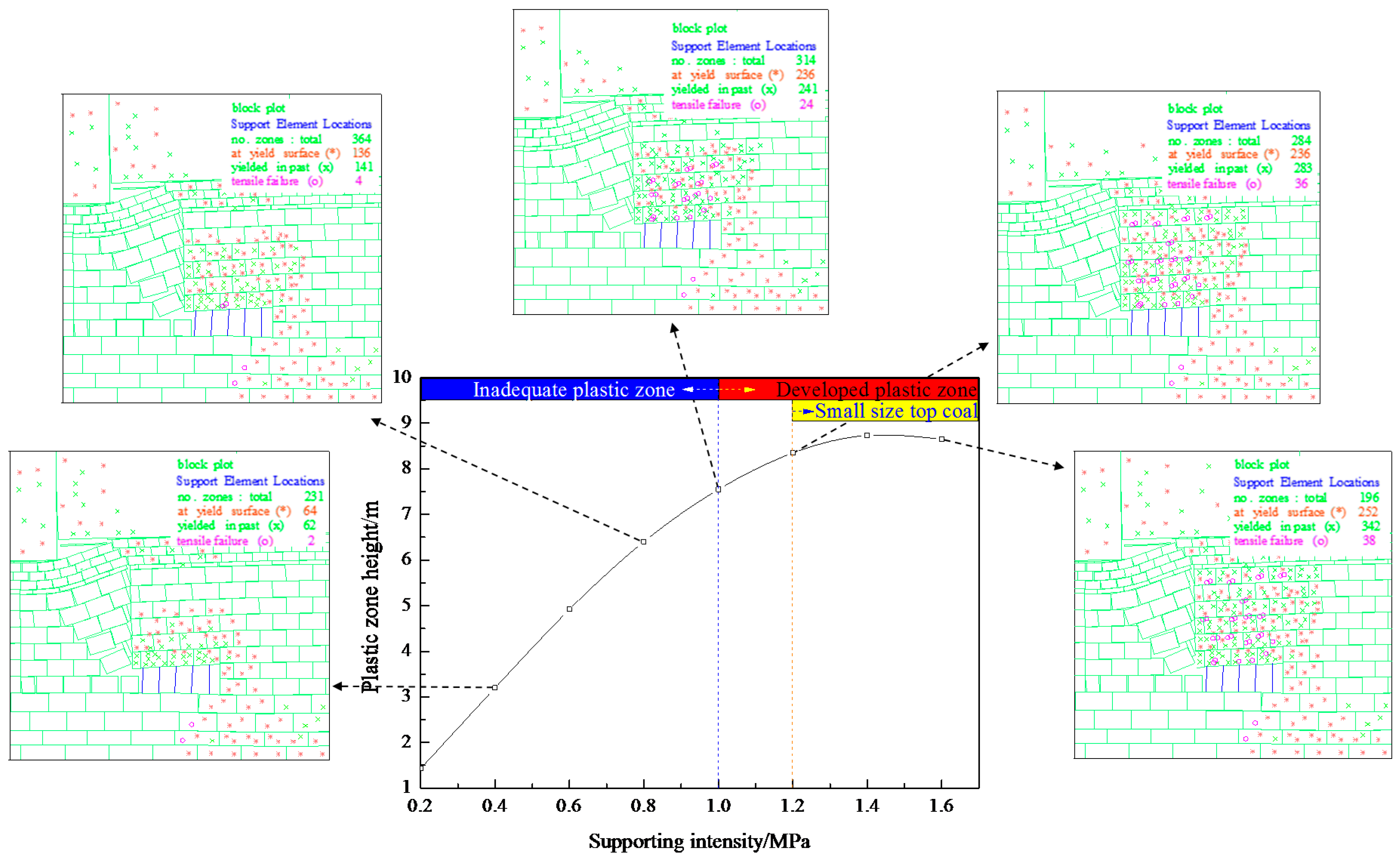
The top coal plastic zone under different support strength in fully-mechanized top coal caving working face 1322 is shown in Figure 5.
As we can see from the Figure 5, the top coal plastic zone expands when the supporting strength becomes larger. When the support strength is more than 1.0 MPa (8264 kN), the plastic zones are developed, which benefits for top coal caving. However, large size coal blocks are formed, which will effect the efficiency of transportation. When the support intensity is over 1.2 MPa, the small blocks of coal are retrieved from the caving process. Meanwhile, when the support strength is 1.6 MPa, only a small plastic zone was formed due to the closure of the cracks. Therefore, 1.2 MPa (10,000 kN) was determined as the required working resistance in the 1322 working face which is equivalent to the working resistance obtained by the inversion optimization method.
4.2. Roof Subsidence under Different Supporting Strength
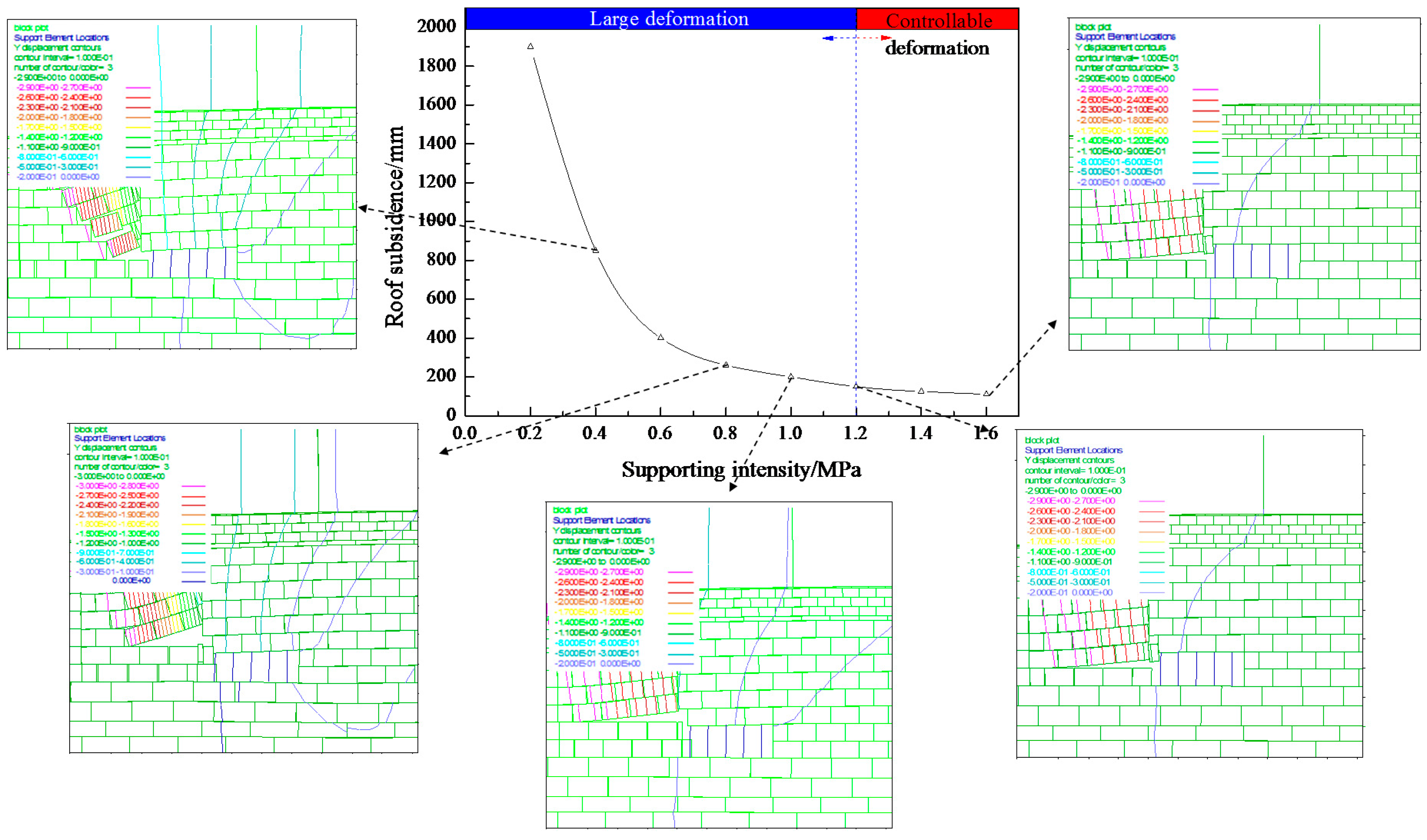
The roof subsidence under different support strength in fully-mechanized top coal caving working face 1322 is shown in Figure 6.
Figure 6 shows that roof subsidence reduced with the increase in the support strength. The roof subsidence under support strength of 1.2 MPa (10,000 kN) is 120 mm, which is 6.3% of subsidence of 0.2 MPa, which belong to the ‘Good’ level according to roof control effect partial index. When the support strength is over 1.2 MPa, there is little to no change in roof subsidence. According to the roof subsidence measured in mine site, the maximum subsidence of the roof is 136 mm when the advancing distance is from 445 m to 619 m, which is very close to the simulation result (120 mm).
5. Engineering Practice
5.1. General Situation of 1322 Caving Working Face
The 1322 caving working face average length along the strike direction was 1230 m and the average width along the dip was 180 m. The average coal thickness is 11.9 m, depth is 258 m–329.3 m. The immediate roof is sandy mudstone, and 2.5 m thick. The main roof is sandstone, with a thickness of 11.7 m. The top-cave hydraulic support model ZF10000/23/35 was selected to employ in the mining site.
5.2. Mine Pressure Behavior of 1322 Caving Working Face
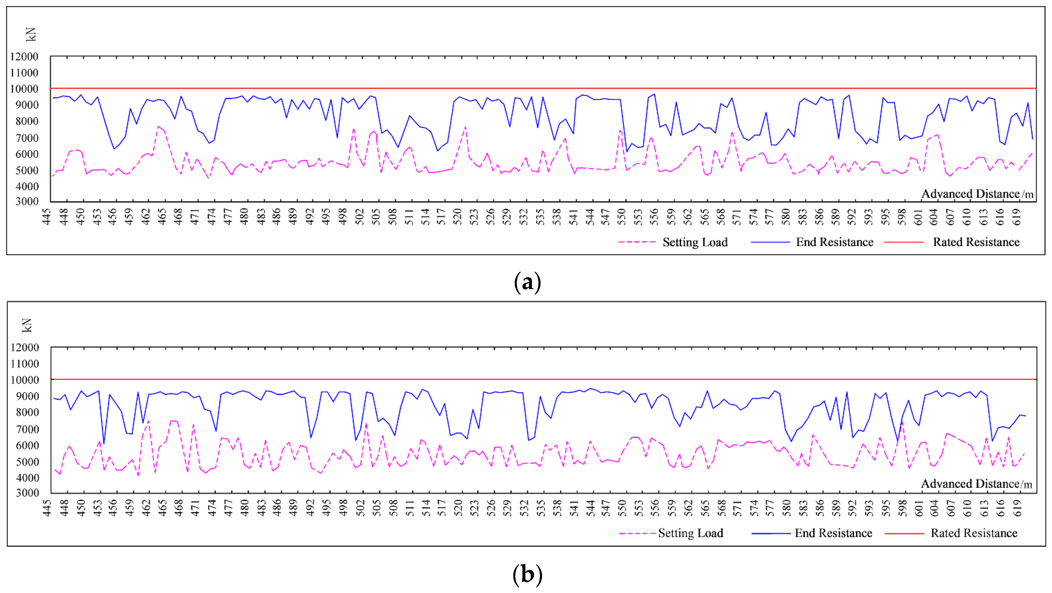
The end working resistance of No. 25 support and No. 60 support was monitored when advancing distance is from 445 m to 619 m were shown in Figure 7.
Figure 7 shows that the periodic weighting step distance (the average distance between the pressure drops) of No. 25 support is 13.5 m, while, the No. 60 support is 22.1 m. The working resistance is 80–90% of working rated resistance. It shows that the support work is in good condition, the support strength is reasonable. No pillar shrinkage and the crushing of the supports was observed in the working face during the advancement of the face.
6. Conclusions
- (1)
- An inversion optimizing method and design flow of working resistance in fully-mechanized top coal caving in shallow thick seam was put forward by considering two very important reference indexes-roof control effect and working resistance overrun percentage. This method and design flow were applied to calculate the working resistance of 1313 working face and 1322 working face and were determined to be with 8786 kN and 10,000 kN. The applied working resistance (8000 kN) is lower than the calculated working resistance (8000 kN) in the 1313 working face which resulted in pillar shrinkage. Therefore, for the 1322 working face, 10,000 kN was determined as the required working resistance.
- (2)
- The simulation model of fully-mechanized top coal caving working face is built by using the UDEC software to justify the method of calculating working resistance with analyzing the top coal cavability and roof subsidence. The roof subsidence under supporting strength of 1.2 MPa (10,000 kN) is 120 mm, which falls within the ‘Good’ range of roof control effect partial. The plastic zone of top coal developed well under supporting strength of 1.2 MPa (10,000 kN), which benefits top coal caving.
- (3)
- The top-cave hydraulic support (ZF10000/23/35) is selected to employ in 1322 plane. The working resistance was monitored during the working face advanced distance is from 445 m to 619 m. The working resistance is 80–90% of working rated resistance. The practice shows that the support worked well and no support pillar shrinkage and crushing happened, which justify the method of calculating working resistance with field feedback.
- (4)
- There are a large number of shallow coal mines where top coal caving method has been applied in the western region of China. Large mining height, special overburden structure, and shallow depth coal seam, many problems were induced in top coal mining working face, such as roof shear, support crushing, and threatened safety of the working face. The research achievements of this paper provide a new support working resistance design flow to guarantee safety mining in those coal mines working face.
Acknowledgments
This work was supported by the National Natural Science Foundation of China (51674241), the Innovative Research Group of the National Natural Science Foundation of China (51421003), and the National Basic Research Program of China (2013CB227905).
Author Contributions
For this paper, Feng Ju put forward study ideas; Peng Huang designed the article structure and wrote the paper; Kashi Vishwanath Jessu revised the whole the English writing style and discussed the design flow with Peng Huang; Meng Xiao collected and analysed the data from mine site; Shuai Guo conducted the numerical simulation and analysed the data.
Conflicts of Interest
The authors declare no conflict of interest.
References
- Yasitli, N.E.; Unver, B. 3D numerical modeling of longwall mining with top-coal caving. Int. J. Rock Mech. Min. Sci. 2005, 42, 219–235. [Google Scholar] [CrossRef]
- Atkinson, T. Thick, steep and irregular coal seam mining. Min. Eng. Lond. 1979, 139, 421–431. [Google Scholar]
- Senkal, S.; Kose, H.; Ermisoglu, N. A study on coal losses and dilution problems in the mining method applied at GLI Tuncbilek Colliery, Madencilik. Bull. Chamb. Min. Eng. Turk. 1988, 27, 5–11. (In Turkish) [Google Scholar]
- Schweitzer, R. Thick seam winning methods in French coal mines. In Proceedings of the International Symposium on Thick Seam Mining Dhanbad; Paper No. 3; Department of Mining Engineering Indian School of Mines: Dhanbad, India, 1977. [Google Scholar]
- Ahcan, R. Mechanization and concentration of thick coal seams mining in SFR Yugoslavia. In Proceedings of the International Symposium on Thick Seam Mining Dhanbad; Paper No. 4; Department of Mining Engineering Indian School of Mines: Dhanbad, India, 1977. [Google Scholar]
- Garg, P.C.; Nath, P.D. Choice of methods for mining thick coal seams in India. In Proceedings of the International Symposium on Thick Seam Mining Dhanbad; Paper No. 10; Department of Mining Engineering Indian School of Mines: Dhanbad, India, 1977. [Google Scholar]
- Yasitli, N.E. Numerical Modeling of Longwall with Top Coal Caving. Master’s Thesis, Hacettepe University, Ankara, Turkey, 2002; p. 148. (In Turkish). [Google Scholar]
- Unver, B.; Yasitli, N.E. Simulation of Sublevel Caving Method Used in thick Coal Seam by Computer; Project No. 0002602008; Hacettepe University Scientific Research Unit: Ankara, Turkey, 2002; p. 148. (In Turkish) [Google Scholar]
- Unver, B.; Yasitli, N.E. Modelling of strata movement with a special reference to caving mechanism in thick seam coal mining. Int. J. Coal Geol. 2006, 66, 227–252. [Google Scholar] [CrossRef]
- Tien, J. Longwall caving in thick seams. Coal Age 1998, 103, 52–61. [Google Scholar]
- Xie, H.P.; Wang, J.H.; Shen, B.H.; Liu, J.Z.; Jiang, P.F.; Zhou, H.W.; Liu, H.; Wu, G. New idea of coal mining: Scientific mining and sustainable mining capacity. J. China Coal Soc. 2012, 37, 1069–1079. [Google Scholar]
- Xu, J.L.; Zhu, W.B.; Wang, X.Z.; Yi, M.S. Classification of key strata structure of overlying strata in shallow coal seam. J. China Coal Soc. 2009, 7, 865–870. [Google Scholar]
- Maosen, Y.I. Study and Application of Key Strata Theory in Shallow Seam of Shendong Mining Area; China University of Mining and Technology: Xuzhou, China, 2008. [Google Scholar]
- Yan, S.H.; Yin, X.W. Discussing about the main theoretical problems of long wall with top coal caving. J. China Coal Soc. 2008, 33, 481–484. [Google Scholar]
- Cai, Y.; Hebblewhite, B.; Onder, U.; Xu, B.; Kelly, M.; Wright, B.; Kraemer, I.; Hebblewhite, B.K. Application of Longwall Top Coal Caving to Australian Operations; CSIRO–ACARP Report C11040; Australian Coal Association Research Program: Brisbane, Australia, 2003. [Google Scholar]
- Mao, D.; Yao, J. Adaptability of longwall top coal caving with high cutting height. J. China Coal Soc. 2010, 35, 1837–1841. [Google Scholar]
- Mao, D.; Kang, L. Longwall top coal caving mining with higher mining height and its feasibility. Coal Min. Technol. 2003, 8, 11–14. [Google Scholar]
- Alehossein, H.; Poulsen, B.A. Stress analysis of longwall top coal caving. Int. J. Rock Mech. Min. Sci. 2010, 47, 30–41. [Google Scholar] [CrossRef]
- Wang, J. Present status and development tendency of fully mechanized coal mining technology and equipment with high cutting height in China. Coal Sci. Technol. 2006, 34, 4–7. [Google Scholar]
- Xiong, R. Investigation of mechanism of roof failure due to weighting over great extent. J. China Coal Soc. 1995, 20, 38–39. [Google Scholar]
- Xu, G. Influence of Initial Support Force on Strata Behavior; Coal Industry Press: Beijing, China, 2011; pp. 247–250. [Google Scholar]
- Xu, G. Cause analysis of large area weighting of full mechanized mining face under non hard roof based on actual measurement data. Coal Min. Technol. 2014, 19, 98–100. [Google Scholar]
- Xu, G. Cause and prevention of powered support jammed in full-mechanized top coal caving mining face in ultra thick seam with watery roof. Coal Sci. Technol. 2016, 44, 1–5. [Google Scholar]
- Zhang, L.; Li, Z.; Jie, X. Mechanism study prevention technology of large area support crushing in fully mechanized top coal caving face of supper thick coal seam. Coal Eng. 2015, 11, 67–69. [Google Scholar]
- Yin, X. Analysis on crushed cause of hydraulic support in fully-mechanized high cutting coal mining face and prevention countermeasures. Coal Sci. Technol. 2014, 42, 26–29. [Google Scholar]
- Yan, S.; Xu, G.; Zhang, X.; Zhan, Z. Reason analyses on large area roof shearting and collapse of hydraulic supports at fully-mechanized top coal caving mining face in ultra thick coal seams. Coal Sci. Technol. 2015, 43, 14–18. [Google Scholar]
- Zhang, D.; Qian, M.; Zhai, M.; Yang, Z. Structural patterns and strata behavior of overlying strata in fully mechanized caving face. Mine Press. Roof Manag. 1994, 4, 13–17. [Google Scholar]
- He, J.; Dou, L.; He, H.; Lu, Z.; Lu, C.; Guo, X. Mechanism study of overlying strata movement inducing rock rurst on top-coal caving face. Chin. J. Mech. Eng. 2011, 30, 3920–3927. [Google Scholar]
- Singh, G.S.P.; Singh, U.K. A numerical modeling approach for assessment of progressive caving of strata and performance of hydraulic powered support in longwall workings. Comput. Geotech. 2009, 36, 1142–1156. [Google Scholar] [CrossRef]
- Singh, G.S.P.; Singh, U.K. Prediction of caving behavior of strata and optimum rating of hydraulic powered support for longwall workings. Int. J. Rock Mech. Min. Sci. 2010, 47, 1–16. [Google Scholar] [CrossRef]
- Su, D.W.H.; Hasenfusgj, M. Geomechanical criteria of longwall face support selection at Consol mines. In Proceedings of the 23rd International Conference on Ground Control in Mining, Morgantown, WV, USA, 3–5 August 2004; pp. 1–10. [Google Scholar]
- Chen, J.S.; Peng, S.S. Design of longwall face support by use of neural network models. Trans. Inst. Min. Metal. Sect. A 1999, 108, A143–A151. [Google Scholar]
- Wang, H.; Wu, Y.; Xie, P.; Zhang, Y. Determination of support working resistance of fully-mechanized caving in steeply dipping seam with ultra thick. J. Liaoning Tech. Univ. 2014, 33, 1020–1024. [Google Scholar]
- Yu, L.; Yan, S.; Liu, Q. Determination of support working resistance of top coal caving in extra thick coal seam. J. China Coal Soc. 2012, 37, 737–742. [Google Scholar]
- Kong, L.; Jiang, F.; Wang, C. Study of reasonable working resistance of support in fully-mechanized sub level caving face in extra-thick coal seam. Chin. J. Mech. Eng. 2010, 11, 2312–2318. [Google Scholar]
- Rausand, M.; Arnljot, H. System Reliability Theory: Models, Statistical Methods, and Applications; John Wiley & Sons: Hoboken, NJ, USA, 2004. [Google Scholar]
- Qian, M.; Shi, P. Mine Pressure and Rock Formation Control; China University of Mining and Technology Press: Xuzhou, China, 2003. [Google Scholar]
- Peng, S.S. Topical areas of research needs in ground control—A state of the art review on coal mine ground control. Int. J. Min. Sci. Technol. 2015, 25, 1–6. [Google Scholar] [CrossRef]
- Fang, X. Study on stability of support-surrounding rock sand its control in fully-mechanized top-coal caving face. Chin. J. Mech. Eng. 2003, 22, 673–678. [Google Scholar]
- Wang, H.; Wu, Y.; Xie, P.; Cao, P.; Guo, F. Research on strata movement and support stability of fully-mechanized sub level caving work face with variable angle in steeply dipping seam. J. China Univ. Min. Technol. 2017, 3, 1–7. [Google Scholar]
Figure 1.
Layout and location of working face 1313.

Figure 2.
Composite column and mechanical parameters of working face 1313.

Figure 3.
Five kinds of working resistance equation of (a) No. 25 and (b) No. 60 support.
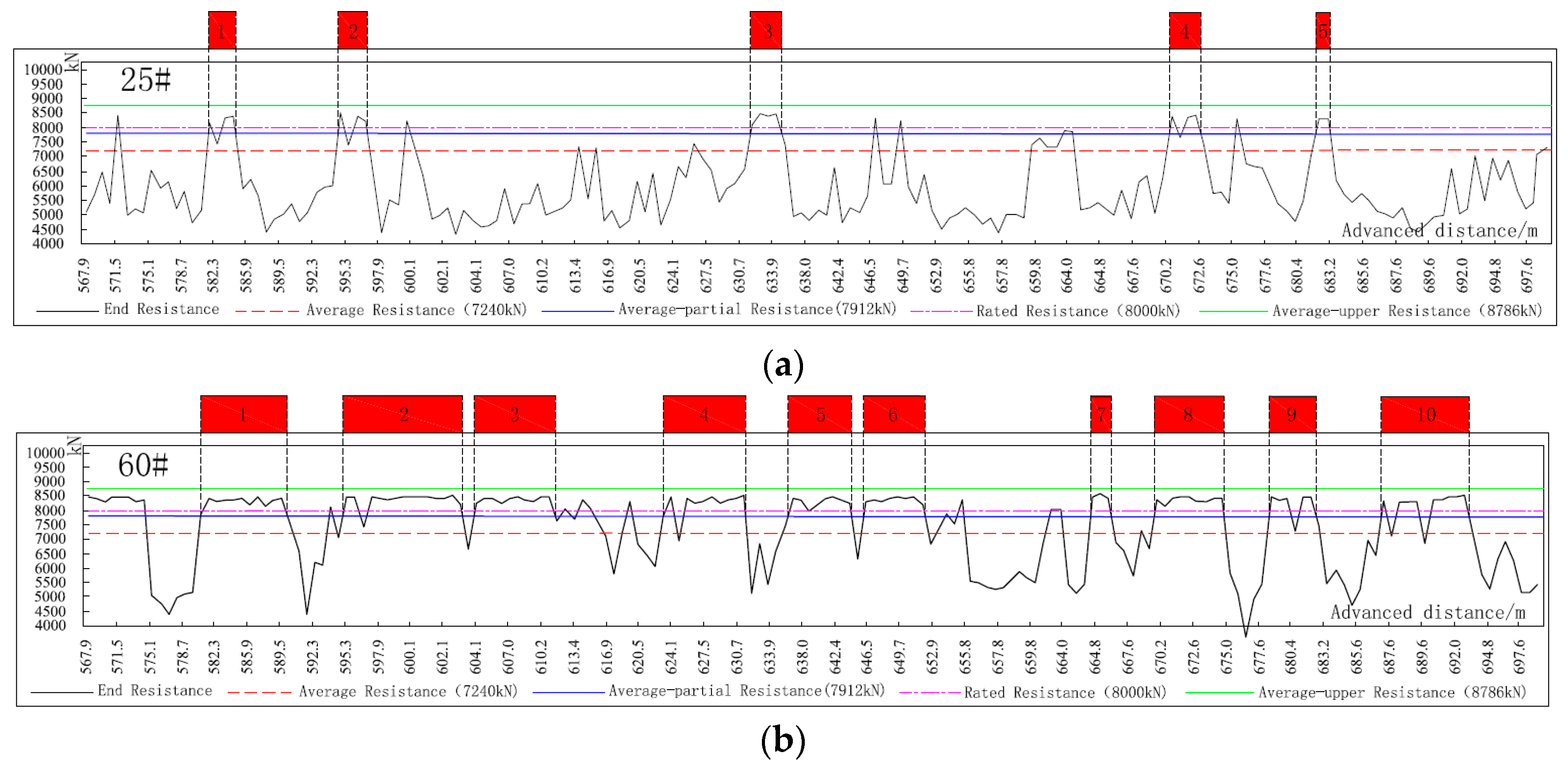
Figure 4.
Working resistance design flow.
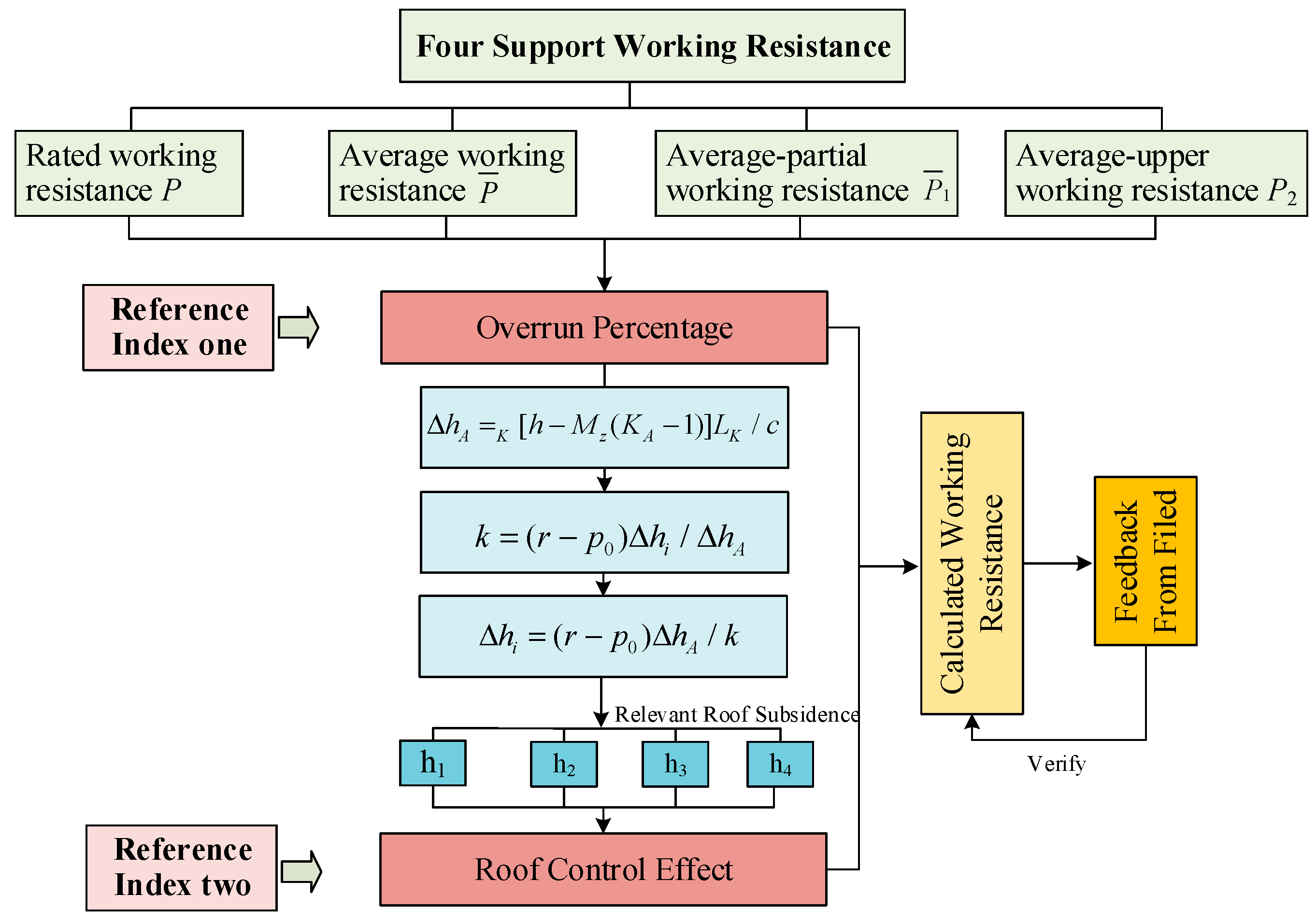
Figure 5.
Top coal plastic zone under different supporting strengths.

Figure 6.
T Roof subsidence under different supporting strength.

Figure 7.
Distribution of support working resistance at normal mining stage measured by (a) No. 25 and (b) No. 60 monitoring unit.
Figure 7.
Distribution of support working resistance at normal mining stage measured by (a) No. 25 and (b) No. 60 monitoring unit.

Table 1.
Roof control effect partial in working face.
| Serial No. | 1 | 2 | 3 | 4 | 5 | 6 | 7 |
|---|---|---|---|---|---|---|---|
| Roof subsidence (mm) | ≤90 | 91–110 | 111–270 | 271–330 | 331–475 | 476–525 | ≥526 |
| Control effect partial | Excellent | Better | Good | Normal | Ordinary | Bad | Poor |
Table 2.
The ratio of six key supports resistance at end of cycle exceeding four values and control effect partial in working face in Jindi mining 1313 working face.
Table 2.
The ratio of six key supports resistance at end of cycle exceeding four values and control effect partial in working face in Jindi mining 1313 working face.
| Serial No. | Four Working Resistance | Value (kN) | Roof Subsidence/mm | Control Effect Partial | Supporting Strength (MPa) | Proportion Type | Overrun Percentage/% | Avg. (%) | |||||
|---|---|---|---|---|---|---|---|---|---|---|---|---|---|
| No. 25 | No. 50 | No. 60 | No. 70 | No. 90 | No. 110 | - | |||||||
| 1 | 8000 | 329 | Normal | 1.00 | A1 | 16.2 | 32.5 | 60.8 | 55.2 | 0.0 | 3.2 | 28.0 | |
| A2 | 5.7 | 17.7 | 39.1 | 26.4 | 0.0 | 0.8 | 16.9 | ||||||
| 2 | 7240 | 462 | Ordinary | 0.90 | A1 | 32.8 | 76.8 | 82.9 | 85.1 | 67.3 | 17.4 | 60.4 | |
| A2 | 11.5 | 41.8 | 53.3 | 40.7 | 38.5 | 6.4 | 31.7 | ||||||
| 3 | 7912 | 351 | Ordinary | 0.99 | A1 | 18.8 | 37.4 | 65.8 | 55.2 | 0.0 | 6.4 | 30.3 | |
| A2 | 6.6 | 20.3 | 42.3 | 26.4 | 0.0 | 1.1 | 16.1 | ||||||
| 4 | 8786 | 267 | Good | 1.10 | A1 | 0 | 0 | 0 | 0 | 0 | 0 | 0 | |
| A2 | 0 | 0 | 0 | 0 | 0 | 0 | 0 | ||||||
| 5 | Cycle No./n | N = 182 | - | - | - | - | 64 | 99 | 117 | 87 | 104 | 46 | 86 |
© 2017 by the authors. Licensee MDPI, Basel, Switzerland. This article is an open access article distributed under the terms and conditions of the Creative Commons Attribution (CC BY) license (http://creativecommons.org/licenses/by/4.0/).
Share and Cite
MDPI and ACS Style
Huang, P.; Ju, F.; Jessu, K.V.; Xiao, M.; Guo, S. Optimization and Practice of Support Working Resistance in Fully-Mechanized Top Coal Caving in Shallow Thick Seam. Energies 2017, 10, 1406. https://doi.org/10.3390/en10091406
AMA Style
Huang P, Ju F, Jessu KV, Xiao M, Guo S. Optimization and Practice of Support Working Resistance in Fully-Mechanized Top Coal Caving in Shallow Thick Seam. Energies. 2017; 10(9):1406. https://doi.org/10.3390/en10091406
Chicago/Turabian StyleHuang, Peng, Feng Ju, Kashi Vishwanath Jessu, Meng Xiao, and Shuai Guo. 2017. "Optimization and Practice of Support Working Resistance in Fully-Mechanized Top Coal Caving in Shallow Thick Seam" Energies 10, no. 9: 1406. https://doi.org/10.3390/en10091406
Note that from the first issue of 2016, this journal uses article numbers instead of page numbers. See further details here.