Article

Hanging Wall Pressure Relief Mechanism of Horizontal Section Top-Coal Caving Face and Its Application—A Case Study of the Urumqi Coalfield, China

1
State Key Laboratory for Geomechanics & Deep Underground Engineering, School of Mechanics and Civil Engineering, China University of Mining and Technology, Xuzhou 221116, China
2
State Key Laboratory of Coal Resources and Safe Mining, School of Mines, China University of Mining and Technology, Xuzhou 221116, China
3
College of Earth and Mineral Sciences, the Pennsylvania State University, University Park, PA 16802, USA
4
Jiangou Coal Mine, Shenxin Energy Company, Urumqi 830001, China
*
Author to whom correspondence should be addressed.
Energies 2017, 10(9), 1371; https://doi.org/10.3390/en10091371
Submission received: 2 August 2017 / Revised: 29 August 2017 / Accepted: 1 September 2017 / Published: 10 September 2017

Abstract

:
Abundant steeply-dipping thick coal seams (SDTCS) have been found in Xinjiang, China, and they are mined largely by the horizontal section top-coal caving (HSTCC) method. The hanging wall of the HSTCC face is nearly vertical and does not fracture easily after the underlying coal is extracted. As a result, stress tends to concentrate in the hanging wall of the lower-section working face (LSWF) and then induce dynamic disasters. In this study, a mechanical model of a HSTCC face’s hanging wall in steeply-dipping seams was constructed to study the characteristics of hanging wall deformation. The mechanism of hanging wall pressure relief by deep-hole blasting (DHB) was analyzed and the effectiveness of DHB was investigated by simulation using the LS-DYNA software. Based on these studies, parameters relevant to pressure relief by DHB were determined and then DHB was applied to the 4301 working face in the Jiangou coal mine. The results show that the average pressure of measured at the 4301 working face decreased about 34% from those at the 4501 face where the hanging wall was not blasted. Accidents related to dynamic rock pressure, such as support crushing and large-scale rib fall, did not occur at the 4301 working face throughout the mining process. Additionally, in order to constrain the surface “V”-shaped collapsed grooves induced by repeated mining of HSTCC faces and prevent the subsequent failure of the surrounding rock on the sides of the collapsed grooves, loess was used to fill in the grooves to provide constraint and dynamic control on the surrounding rock. The two complementary technologies proposed in this study provide a guide on how to control hanging wall of SDTCS in similar conditions.

1. Introduction

SDTCS is widely distributed in coal-producing areas worldwide, such as the Urumqi coalfield in China, the Donbass coalfield in Ukraine, the Karaganda coalfield in Kazakhstan, the Ruhr coalfield in Germany, the Lorraine coalfield in French, and the West Virginia coalfield in America [1]. In particular, the SDTCS in the Urumqi coalfield have reserves amounting to over 30% of the world’s coal reserves in similar seams [2]. In thick seams that dip steeply at 45–90°, working faces usually extend horizontally as it is difficult to advance along the dip direction. Such seams are typically divided into several horizontal sections roughly parallel to the strike and coal is first mined from the bottom, allowing the top coal to cave behind the face. This mining method is referred to as HSTCC and can improve extraction efficiency [3,4,5]. However during mining, the hanging wall does not fracture and cave in time, leading to stress concentration in the hanging wall of the LSWF that can then induce dynamic disasters. Meanwhile, due to the high intensity of mining, large number of sections, and short distances between faces, fully-mechanized caving can repeatedly disturb the overlying goaf thus leading to surface “V”-shaped collapsed grooves [6,7]. Therefore, it is necessary to study the deformation behavior of the HSTCC face’s hanging wall and develop effective technologies for controlling hanging wall under such conditions.
Theoretical studies have been conducted into the structure of hanging wall over SDTCS. For example, Kulakov [8,9] researched how rock pressure varied with different depth of steep coal bed and coal pillar width. Klishin et al. [10,11] developed a sublevel caving technology, and analyzed the laws of top coal movement during caving and the effects of different caving methods and other factors on top coal movement. Shi and Zhang [12] proposed a theoretical structure called “arch of spanning strata” and analyzed the sliding instability and structure instability of this structure as well as the two instability modes on strata behavior at working face. In a study of SDTCS, Lai et al. [13] discovered a noticeably asymmetric distribution of vertical displacement of overburden at the HSTCC face. He suggested that the top coal and overlying residual gangue together formed an asymmetrical arch structure, which then developed into a typical ellipsoidal structure.
According to research on hanging wall stability control for SDTCS, hydraulic fracturing and blasting are two well-established technologies currently used to relieve stress in hanging wall. Hanging wall weakening by hydraulic fracturing requires the strata to be fairly water-absorbent and is too inefficient to ensure a normal rate of face advance [14,15,16]. In contrast, blasting is subject to fewer technical limitations, highly efficient and effective in weakening strata, and thus more widely adopted [17,18,19]. At present, the technology of pressure relief by blasting is applied primarily to gently dipping seams, but its application to SDTCS is rarely reported.
Currently, surface collapse over goaf areas is controlled mainly by goaf backfilling, grouting bed separations in the overburden, and surface treatment [20,21,22]. Goaf backfilling is obviously unsuitable for SDTCS that are mined with HSTCC method, because the upper goaf area in SDTCS is susceptible to repeated disturbances caused by mining at the LSWF [23,24]. As the hanging wall over steep coal bed spans only one side of the face, it plays a limited role in supporting the upper goaf. This means that grouting bed separations in overburden is ineffective for such seams [25,26]. Since loess is widely distributed and easy availability from the surface of the Urumqi coalfield, it is relatively practical and feasible to fill in “V”-shaped collapsed grooves above SDTCS with loess. The effectiveness of this method has been demonstrated by practical application in surface collapse control over the past years [5].
This study analyzed the deformation behavior of HSTCC face’ hanging wall, with the example of the Jiangou coal mine in the Urumqi coalfield. The technology of pressure relief by DHB was proposed as a way to facilitate fracturing of the hanging wall above goaf so as to prevent dynamic disasters induced by stress concentration in the hanging wall of LSWF. This technology was applied to the 4301 working face. Furthermore, the method of loess filling was employed to repair surface collapsed grooves in order to minimize surface damage caused by SDTCS mining.

2. HSTCC Method

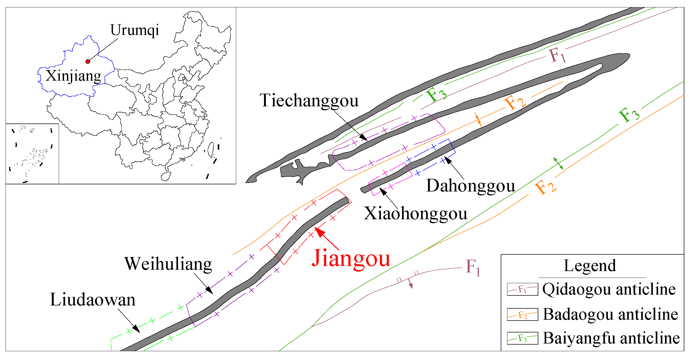
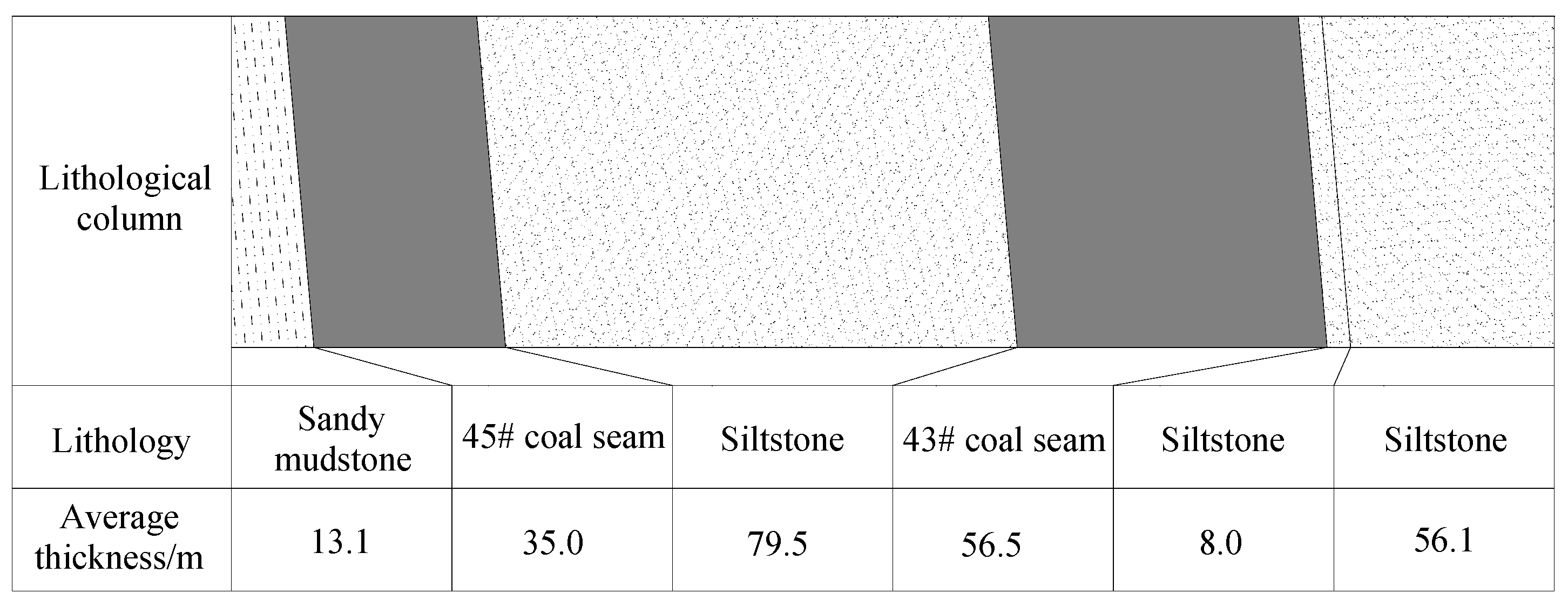
2.1. Geology Conditions

The Urumqi coalfield is representative of Chinese mining areas that work with SDTCS, account for over 1/4 of the country’s SDTCS in terms of coal reserves [27]. With a total of 33 seams, the Middle Jurassic Xishanyao Formation is the main coal-bearing formation in this coalfield. These seams range from 63° to 88° in average dip and their total workable thickness is between 120 and 135 m. Therefore, they are regarded as a steeply-dipping closely-spaced thick seams group. Located in the central part of the Urumqi coalfield (Figure 1), the Jiangou coal mine is a highly productive and efficient mine with an annual coal production of 1.8 million tons. The main seams being mined are the 43# (B3–6) and 45# (B1–2) seam (Figure 2).

2.2. Mining Method

The conventional method of sublevel caving, which divides a seam along its thickness into sections, is not applicable to steeply-dipping seams. Therefore, the Jiangou coal mine adopts the HSTCC method. At the HSTCC face, the coal seam is divided along its dip direction into several horizontal sections of certain heights and the coal is first cut from the bottom of working face, leaving the top coal to collapse. With multiple advantages such as lower tunneling ratio, higher output and economic efficiency, HSTCC has become the principal method for mining SDTCS in Xinjiang [28].
The mining sequence of HSTCC method is: shearer cutting coal → advancing hydraulic supports → advancing front scraper conveyor → caving top coal → pulling rear scraper conveyor. The caving method of HSTCC is same as the full-mechanized longwall top coal caving face in gently dipped coal seams. However, due to the working face along dip direction, which is equal to the thickness of the coal seam, is relatively shorter than the normal length, a relatively faster mining speed can be achieved along the strike direction of the working face.

2.2.1. Mining Conditions
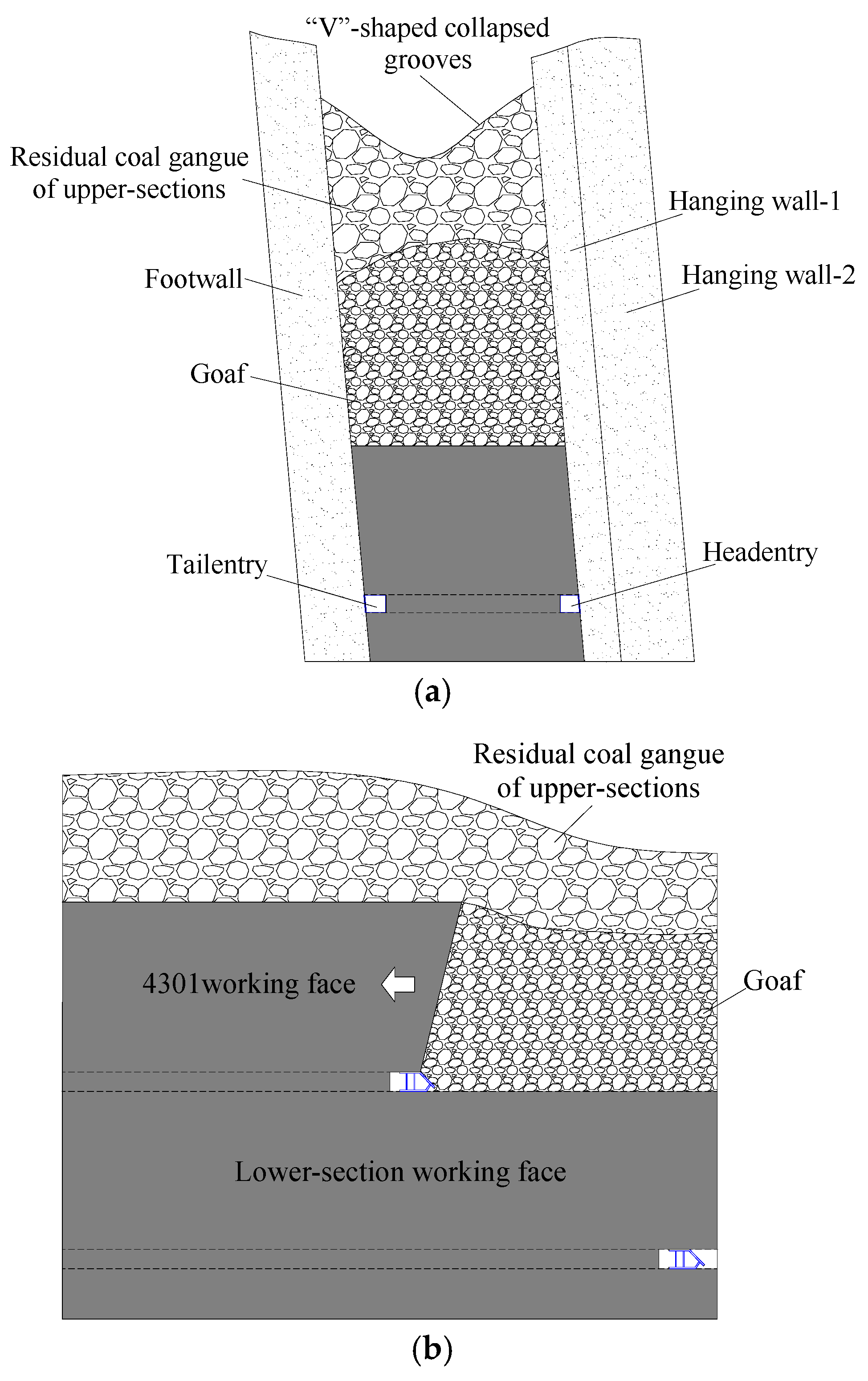
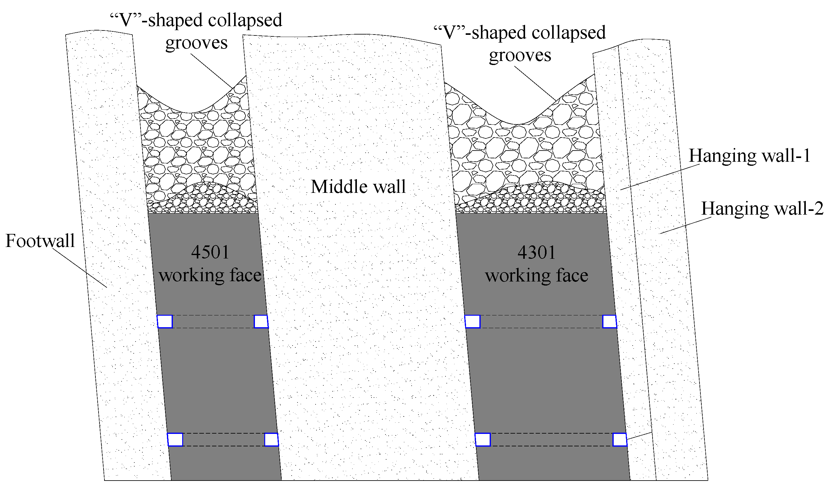
The 4301 working face of the Jiangou coal mine is buried at depths of 240–290 m and measures 56.5 m wide and 1000 m long in its direction of advance. The mining section height is 24 m; the cutting height is 3.2 m and caving height is 20.8 m, with the caving ratio being about 1:7. The shearer has a cutting depth of 0.6 m and the face advances 0.6 m during a mining cycle. The interval distance between caving cycles is 1.2 m. Figure 3 shows the stratigraphic column of this face. The hanging wall is composed primarily of siltstone and dips at 85°; it has a compressive strength of 25.6 MPa and tensile strength of 3.1 MPa.

2.2.2. Face Layout

As shown in Figure 4, the HSTCC face is perpendicular to the strike of the seam. The headentry and tailentry along the sides of the face, driven in the same level, are close to the hanging wall and footwall, respectively.

3. Deformation Behavior of HSTCC Face’s Hanging Wall

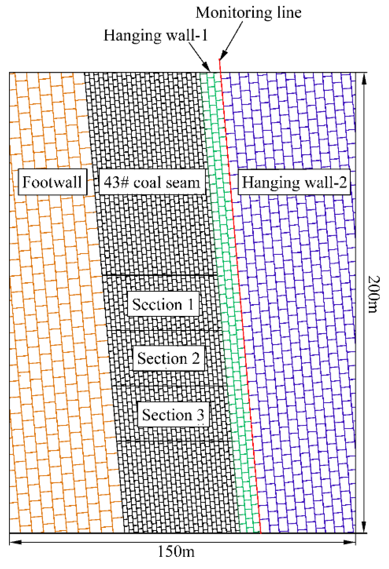
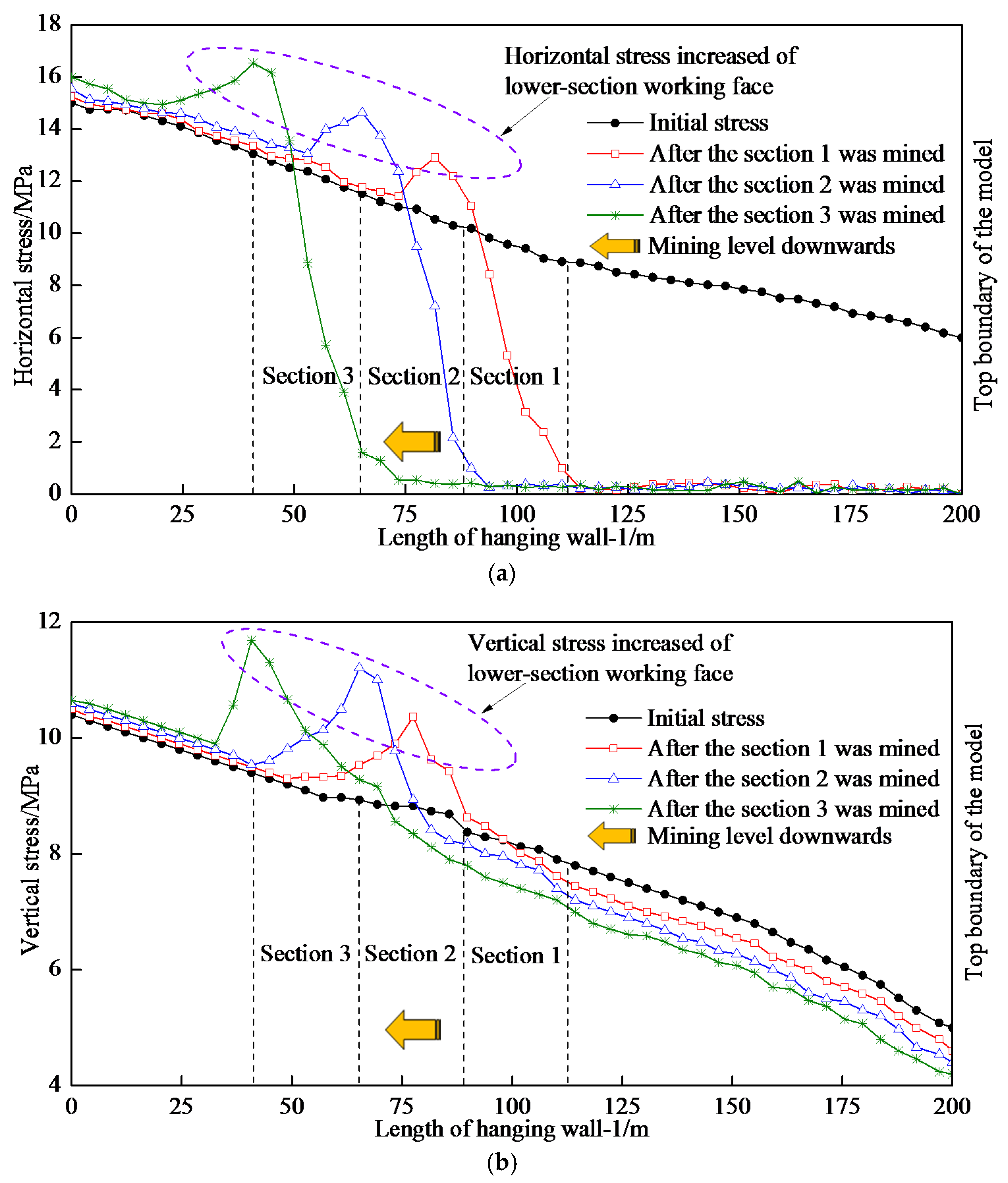
3.1. Numerical Simulation of HSTCC

The UDEC 4.0 software was used to simulate the mining process of the HSTCC face. To facilitate modeling, the strata thickness was set at an integer. A numerical simulation model with three horizontal sections and dimensions of 150 m × 200 m was constructed. To monitor the laws of stress change in the hanging wall during mining, a monitoring line was arranged in the hanging wall, 8 m above the coal seam (Figure 5).
The failure criterion used in the numerical analyses is Mohr–Coulomb model. In order to calibrate the input parameters of the modeling, the Mohr–Coulomb model was used to simulate the uniaxial compression test and the results are compared with the experimental data. The parameters of this model are used in the following simulations, until the numerical simulation results of the stress–strain characteristics are in good agreement with that of experimental data. The mechanical parameters of the models are shown in Table 1 and Table 2. Both the left and right boundaries of the model were fixed by displacement, limited the displacement in the x direction. The bottom boundary was fixed by displacement, limited the displacement in the y direction.
Due to the particular geological conditions of strata and characteristics of HSTCC method, the HSTCC face was located underneath the upper-sections goaf, and above the working face lay the top coal and residual gangue left behind after the upper-sections were mined, rather than immediate roof and main roof. After the top coal was drawn by caving behind the face, the overlying gangue tended to collapse. Since the width of HSTCC face was about 50 m generally, the disturbance along the dip caused by mining was too limited to fracture the hanging wall easily [29], as illustrated in Figure 6.
The laws of horizontal stress and vertical stress change during mining were analyzed (Figure 7). The results show that after the section 1 was mined, the hanging wall-1 of the LSWF was subject to an average horizontal stress of 11.9 MPa, up 10.2% from the initial stress of 10.8 MPa. After the section 2 was mined, the average horizontal stress in the hanging wall-1 of the LSWF reached 13.6 MPa, 9.7% higher than the initial stress of 12.4 MPa. The mining of the section 3 led to 10.1% increase in that stress from 13.9 MPa to 15.3 MPa. The hanging wall-1 of the HSTCC face underwent an overall decrease in horizontal stress throughout the mining process, primarily because the caving of top coal resulted in loss of support for the hanging wall and thereby relieved the stress in the hanging wall.
After the section 1 was mined, the average vertical stress in the hanging wall-1 of the LSWF was 9.6 MPa, 9.1% increase from the initial stress of 8.8 MPa. After the section 2 was mined, the average vertical stress in the hanging wall-1 was 10.2 MPa, 13.3% higher than the initial stress of 9.0 MPa. After the section 3 was mined, the average vertical stress in the LSWF’s hanging wall-1 reached up to 10.8 MPa after 16.1% increase from 9.3 MPa. It follows that during the mining process, the vertical stress in the hanging wall-1 of the LSWF increased and the rate of increase grew as the mining level downwards [29]. This finding suggests that if the hanging wall of HSTCC face is not preconditioned, the hanging wall of the LSWF would tend to concentrate stress during mining and then induce dynamic disasters.

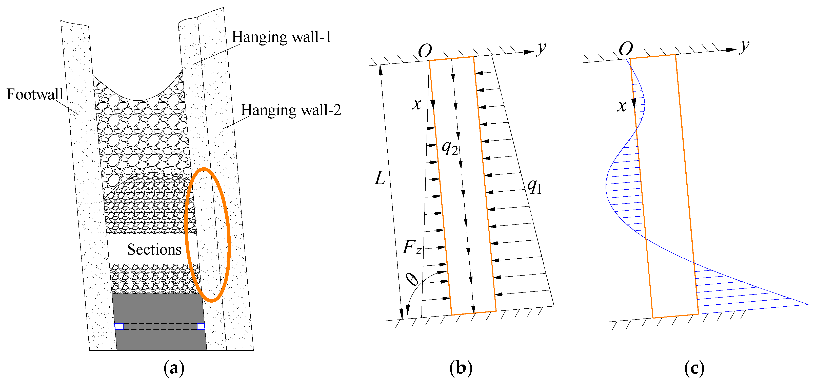
3.2. Mechanical Model of HSTCC Face’s Hanging Wall

After the top coal was drawn from the HSTCC face, the overlying gangue collapsed and accumulated above the LSWF. The hanging wall of the LSWF exhibited bending deformation, because the gangue accumulation was too loose to impose a sufficient constraint on it. After the coal beneath was extracted, the hanging wall-1 of the HSTCC face, made up of 8-m-thick sandstone, did not fracture easily and thus provided support for the overlying strata (Figure 8a). Therefore investigating the deformation characteristics of the hanging wall-1 can reveal the mechanical behavior of the HSTCC face’s hanging wall.
The hanging wall-1 of the face was simplified to a clamped-clamped elastic beam [30,31,32,33,34,35], as shown in Figure 8b. Since the strata were nearly-vertical, the relative motions between strata were not taken into consideration in the analysis. Then the hanging wall-2 exerted only a normal load on the hanging wall-1. Meanwhile, the magnitude of the supporting force exerted on the hanging wall-1 by the caved gangue depended on the gangue’s strength and compactness. We can reasonably assume that this supporting force increased linearly downward the hanging wall-1 [36,37]. The forces acting on the hanging wall-1 can be calculated using the following equations:
q 1 = ( q 0 + γ L j x sin θ ) ( cos θ + λ sin θ ) ,   q 2 = L j ( q 0 + γ x sin θ ) sin θ
F z = k x
where q0 is the load on the upper clamped end of the hanging wall-1 (kN/m3);
  • q1 is the normal load exerted on the hanging wall-1 by the hanging wall-2 (kN/m3);
  • q2 is the tangential load on the hanging wall-1 (kN/m3);
  • γ is the bulk density of the hanging wall strata (kN/m3);
  • θ is the dip of hanging wall strata;
  • Lj is the total thickness of the hanging wall-1 and hanging wall-2 (m);
  • Fz is the supporting force exerted on the hanging wall-1 by the caved gangue (kN);
  • Ld is the height of the goaf after several sections were mined (m);
  • λ is lateral pressure coefficient;
  • k is the distribution factor of the supporting force applied to the hanging wall-1 by the caved gangue (kN/m3).

3.2.1. Deformation Caused by the Normal Load

According to the principle of force superposition under small deformation, the deformation of the hanging wall-1 can be decomposed into two components, one caused by q1 and the other by Fz. Then the bending moment in the hanging wall-1 can be expressed in the following equation:
M x = q 0 L 2 ( cos θ + λ sin θ ) 12 ( 6 x L 6 x 2 L 2 1 ) + γ L j x L 2 sin θ ( cos θ + λ sin θ ) k x L 2 60 ( 9 x L 10 x 3 L 3 2 )
Based on the field conditions in Jiangou Coal Mine, the following parameters can be obtained for the equations mentioned above: θ = 85°, Lj = 64.1 m, λ = 0.3 [36], and k = 105 kN/m3 [33]. Then q0 over a unit length of hanging wall-1 along the strike was q0 = γhLj = 25 × 240 × 64.1 = 3.846 × 10⁵ kN/m. The distribution of bending moment in the hanging wall-1, denoted Mx, was calculated for three different goaf heights: L = 24 m, 48 m, and 72 m, i.e., the goaf heights respectively after the sections 1, 2, 3 was mined.
During mining, the hanging wall-1 deformed under the action of the normal load and the maximum bending moment occurred at its lower clamped end. The bending moment exerted an effect primarily upon the top coal and hanging wall of the LSWF, resulting in rock pressure increase and significant deformation of the rock surrounding the hanging wall-side entry. After the section 1 was mined, the maximum bending moment was 61.6 kN·m. After the section 2 was mined, that value was 521.1 kN·m, representing a 8.5-fold increase from that observed after the section 1 was mined. After the section 3 was mined, the maximum bending moment reached up to 1790.6 kN·m, a 29.1-fold increase from that observed after the section 1 was mined. These suggest that, as the mining level downwards, the bending moment in the hanging wall-1 increased by orders of magnitude and its effect on the LSWF grew gradually, as shown in Figure 9.

3.2.2. Deformation Caused by the Tangential Load

As the hanging wall-1 was nearly-vertical, its lower clamped end was subjected to a greater load than the other parts. The tangential load q2 was transferred through the hanging wall-1 to the LSWF [38]. It is clear from Equation (1) that q2 is directly proportional to the length of hanging wall-1 behind the face, denoted x, and tends to increase as the mining level downwards. The analysis above concludes that the hanging wall-1 of HSTCC face does not fracture easily, which poses a threat to the safe production. It is therefore necessary to artificially cut off the hanging walk behind the face by DHB, in order to reduce the energy stored in the hanging wall and the stress in the LSWF.

4. The DHB Technology for Pressure Relief

4.1. Mechanism of Pressure Relief by DHB

There are two types of hanging wall blasting: shallow-hole blasting (blasting hole length < 5 m) and deep-hole blasting (blasting hole length ≥ 5 m). In shallow-hole blasting, the detonation of explosives creates shallow cracks in the hanging wall and tensile stress then arise from these cracks during bending induce hanging wall fracture. In contrast, DHB directly uses explosion to fracture hanging wall and reduce the energy it accumulates [39,40]. Given the total thickness of the hanging wall-1 and hanging wall-2 over the 43# seam was 64.1 m, the blasting holes should be longer than 5 m in order to ensure the effectiveness of blasting in relieving stress. Therefore, the technology of hanging wall pressure relief discussed in this study accounts to DHB.
The nearly-vertical hanging wall did not fracture easily after coal mined, which led to stress concentration in the hanging wall, and deformation of LSWF surrounding rock. Implementing DHB technology for the HSTCC face’s hanging wall can reduce the bearing capacity of the surrounding rock and thus weaken the hanging wall. On the one hand, the explosion can cut off the hanging wall behind the face and reduce the bending moment produced by the normal load on the hanging wall. On the other hand, the fractured hanging wall can disperse the tangential load on the hanging wall and act as a cushion against its transfer to the LSWF.

4.2. Theoretical Analysis of DHB and Numerical Simulation

4.2.1. Theoretical Analysis of DHB

After the explosive in blasting holes explodes, the rock surrounding the blasting holes can be roughly divided into three zones: crushed zone, fractured zone and elastic zone. Rock masses in both the crushed and fractured zones have been broken, while that in the elastic zone, which is subject to slight disturbance, remains intact. Therefore, the effective damage zone around blasting holes normally refers to the crushed zone and the fractured zone together. The radii of the two zones can be calculated using the following equations [40,41,42]:
R c = ( ρ 0 D v 2 n K 2 γ l c B 8 2 σ c d ) 1 a r b
R ρ = ( σ c d σ t d ) 1 β R c
in which:
{ A = 2 ρ C p ρ C p + ρ 0 D v B = ( 1 + b ) 2 + ( 1 + b 2 ) 2 μ d ( 1 b ) 2 a = 2 μ d 1 μ d b = μ d 1 μ d β = 2 3 μ d 1 μ d
where Rc and Rρ are the radii of the crushed zone and fractured zone, respectively (m);
  • rb and rc are the radii of blasting holes and explosive charge, respectively (m);
  • ρ and ρ0 are hanging wall rock density and explosive density, respectively (kg/m3);
  • Cp and Dv are speed of sound in the rock blasted and detonation velocity (m/s);
  • a is the attenuation coefficient of load;
  • b is lateral stress coefficient;
  • ud is the dynamic Poisson’s ratio of the rock, ud = 0.8u; in which u is the Poisson’s ratio of the rock;
  • K is the radial decoupling coefficient of charge, K = rb/rc;
  • lc is the axial decoupling coefficient of charge, lc = 1;
  • n is the coefficient of pressure on blasting holes wall due to the impact of the expanding detonation products, normally n = 10;
  • γ is the adiabatic expansion coefficient of the detonation products, usually set at 3;
  • σcd and σtd are the dynamic compressive strength and tensile strength of the rock, respectively; σcd = ε1/3σc and σtd = ε1/3σd, in which σc and σd are compressive strength and tensile strength of the rock, respectively; ε is the strain rate of the load (s−1), normally ε = 10 s−1.
Based on the field conditions in Jiangou Coal Mine and the results of laboratory experiments, the following parameters can be obtained for the equations mentioned above: rb = 0.05 m; rc = 0.035 m; ρ = 2550 kg/m3; ρ0 = 1000 kg/m3; Dv = 3600 m/s; Cp = 3500 m/s; u = 0.25; σc = 25.6 MPa and σd = 3.1 MPa. The radii of the crushed and fractured zones were then calculated using the equations above: Rc = 0.699 m and Rρ = 2.338 m. So the effective damage zone had a radius of 3.037 m. In theory, therefore, the space between blasting holes should not exceed 6.074 m.

4.2.2. Numerical Simulation of DHB

LS-DYNA 970, a software for dynamic analysis, was used to simulate the process of DHB. The surrounding rock was modeled with MAT_PLASTIC_KINEMATIC, a kinematic hardening plastic model provided by this software, and the explosive material was modeled with MAT_HIGH_EXPLOSIVE_BURN. The Jones–Wilkens–Lee (JWL) state equation was used to describe the pressure-volume relationship for the products of detonation of a high explosive [41,42]. Based on the actual conditions of the 4301 working face, the blasting holes space was determined to be 6 m. Blasting holes with a diameter of 0.1 m were made in the hanging wall model with dimensions of 20 m × 8 m. A non-radioactive boundary was applied to the model. The three monitoring points in the model were 1 m, 2 m, and 3 m from the blasting holes, respectively, as shown in Figure 10.
Figure 11 implies that the effective stress waves generated by the explosion propagated evenly in all directions. As shown in the figure, 119 μs after detonation, the boundary of the region affected by the effective stress waves was 0.6 m from the blasting holes, roughly equal to the radius of the crushed zone around blasting holes. The affected region extended 3.2 m beyond the blasting holes, including the aforementioned crushed and fractured zones, 1380 μs after detonation.
Figure 12 illustrates the distribution of effective stress around the blasting holes. It is found that the effective stress produced by blasting decreased with increasing distance from the blasting holes. The peak effective stress of monitoring point 1 was 255.3 MPa, occurred at 425 μs after detonation. The peak effective stress of monitoring point 2 was 125.5 MPa, occurred at 900 μs after detonation. The peak effective stress of monitoring point 3 were 70.0 MPa and 75.1 MPa successively, occurred at 1250 μs and 1390 us after detonation. This peak effective stress of monitoring point 3 occurred two times, possibly because the superposition of effective stress waves from the two blasting holes. As the compressive strength of the hanging wall of the 4301 working face, at 25.6 MPa, was significantly lower than the effective stress produced by DHB, the hanging wall rock easily failed by yielding under such stress, and the fractured zone developed. A comprehensive analysis of the results of the theoretical calculation and numerical simulation suggests that blasting holes space of 6 m can ensure effective weakening of hanging wall under the 4301 working face’s geological conditions.

5. Engineering Application

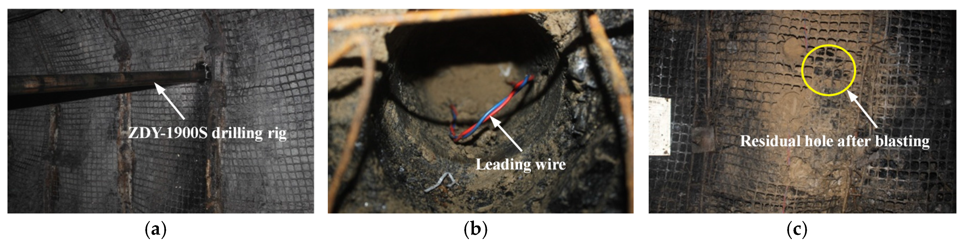
5.1. Determination of Blasting Parameters

The DHB technology was implemented to weaken the hanging wall of the 4301 working face. Blasting holes were drilled into the hanging wall along the headentry in a fan-shaped pattern. They were loaded with emulsion-based explosive; the mass of explosive per meter of hole was 7.5 kg/m. Then these holes were connected in series. As the face advanced, the blasting site was set right above the rear scraper conveyor, as shown in Figure 13a. The details of the blasting site are shown in Figure 14.
(1) Blasting holes diameter
A ZDY-1900S drill rig was employed to drill blasting holes with a diameter of 100 mm. The explosive was packaged in PVC tubes and then placed into the blasting holes. These PVC tubes had an outer diameter of 90 mm and inner diameter of 86 mm, and the explosive charge diameter was 70 mm (Figure 13c).
(2) Blasting holes length
Experiences from previous projects suggest that blasting hole length should be more than half of the hanging wall’s thickness to be blasted [43]. Since the total thickness of the hanging wall-1 and hanging wall-2 of the 4301 working face was about 64.1 m, the blasting holes were designed to be 35 m long. The ratio of sealing length to hole length is normally between 25 and 30%. To ensure adequate sealing performance, the ratio was set at 30% for this face, and the corresponding sealing length was 10.5 m. For convenient field operation, the sealing length and charge length were determined to be 10 m and 25 m, respectively.
(3) Blasting holes space
As stated above, blasting holes space of 6 m can ensure effective weakening of hanging wall. Given the fan-shaped pattern of blasting holes in this scheme, the space between blasting holes would vary with different length, but it was only necessary to ensure that the bottoms of two adjacent holes were no more than 6 m apart. If the angle between two blasting holes is 10°, their bottoms are 6.1 m apart. Though this space is slightly greater than 6 m, it is acceptable, because the hanging wall can be further weakened by the movement of overburden driven by blasting. Therefore, the blasting holes were designed to be at an angle of 15°, 25°, and 35°, respectively, to the horizontal direction (Figure 13b).
(4) Blasting interval
Experience from an adjacent face suggest that the periodic weighting interval of the 4301 working face should be approximately 22 m. To follow the principle that blasting interval must not exceed periodic weighting step and to minimize the amount of work [44], the blasting interval was determined to be 20 m for the 4301 working face (Figure 13a).

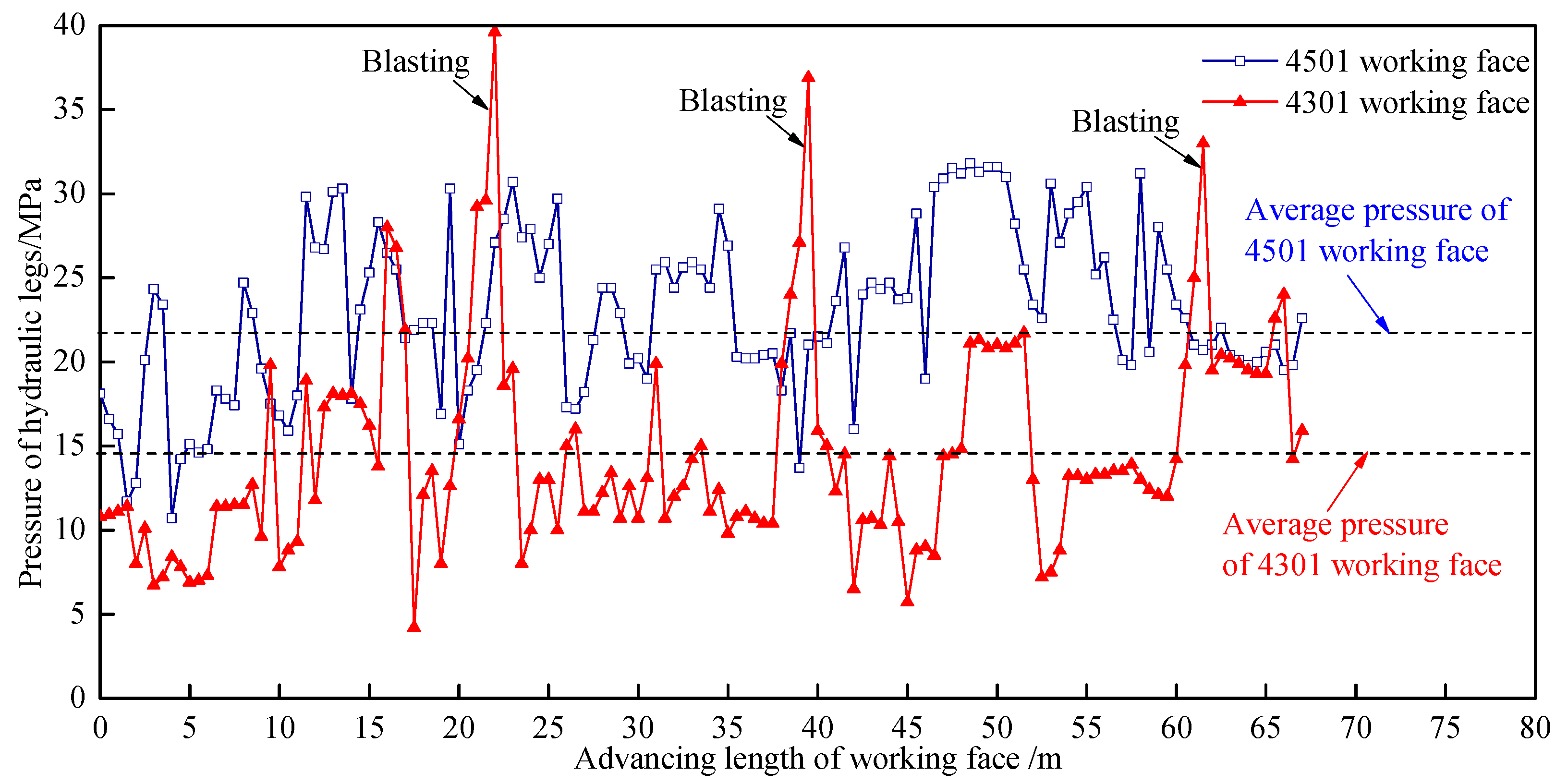
5.2. Effectiveness of DHB in Hanging Wall Pressure Relief

4501 and 4301 working face are located at the same level, but the 4501 working face mines the 45# coal seam (Figure 15). The equipment, mining technology and mining section height of 4501 working face are same as the 4301 working face. 4501 working face is measured 35 m wide and 800 m long in its direction of advance. These two working faces are equipped with KJ377 type on-line monitoring system to record the pressure of hydraulic supports’ legs. The average pressure of hydraulic legs in working face were monitored while mining; moreover, changes of those values in two working faces, from the open-cut to advanced 80 m, were compared in this section.
After DHB was applied to the 4301 working face for hanging wall pressure relief, the pressure of hydraulic legs along the face showed a sharp increase every 20 m of face advancing, then followed by a slowly paced down. This is consistent with the blasting intervals designed. The average pressure measured at the 4301 working face was 14.7 MPa, 34% decrease compared to the 22.3 MPa at the 4501 working face, which is located in the same mining level and to which the DHB technology was not applied (Figure 16).
When the 4501 working face moved forward 100 m from the open-off cut, the supports at the end of the headentry were crushed, and the exit of the face and the tailentry were blocked off. As the distance between the face and the open-off cut reached 230 m, large-scale rib fall took place along the 15 m headentry section ahead of the face, and stopped the face production. During the mining process, the 4501 face has seen a total of 7 major accidents related to dynamic rock pressure and exhibited noticeable deformation of the rock surrounding roadways. At the 4301 working face, by comparison, no support crushing, large-scale rib fall or other manifestations of dynamic rock pressure have occurred throughout the mining process. These demonstrate that the energy stored in the nearly-vertical hanging wall was effectively released by DHB. By far, the technology of pressure relief by DHB has been applied to five faces in the Jiangou coal mine. 7.5 million tons of coal have been mined safely, without occurrence of accidents related to dynamic rock pressure throughout the mining processes.

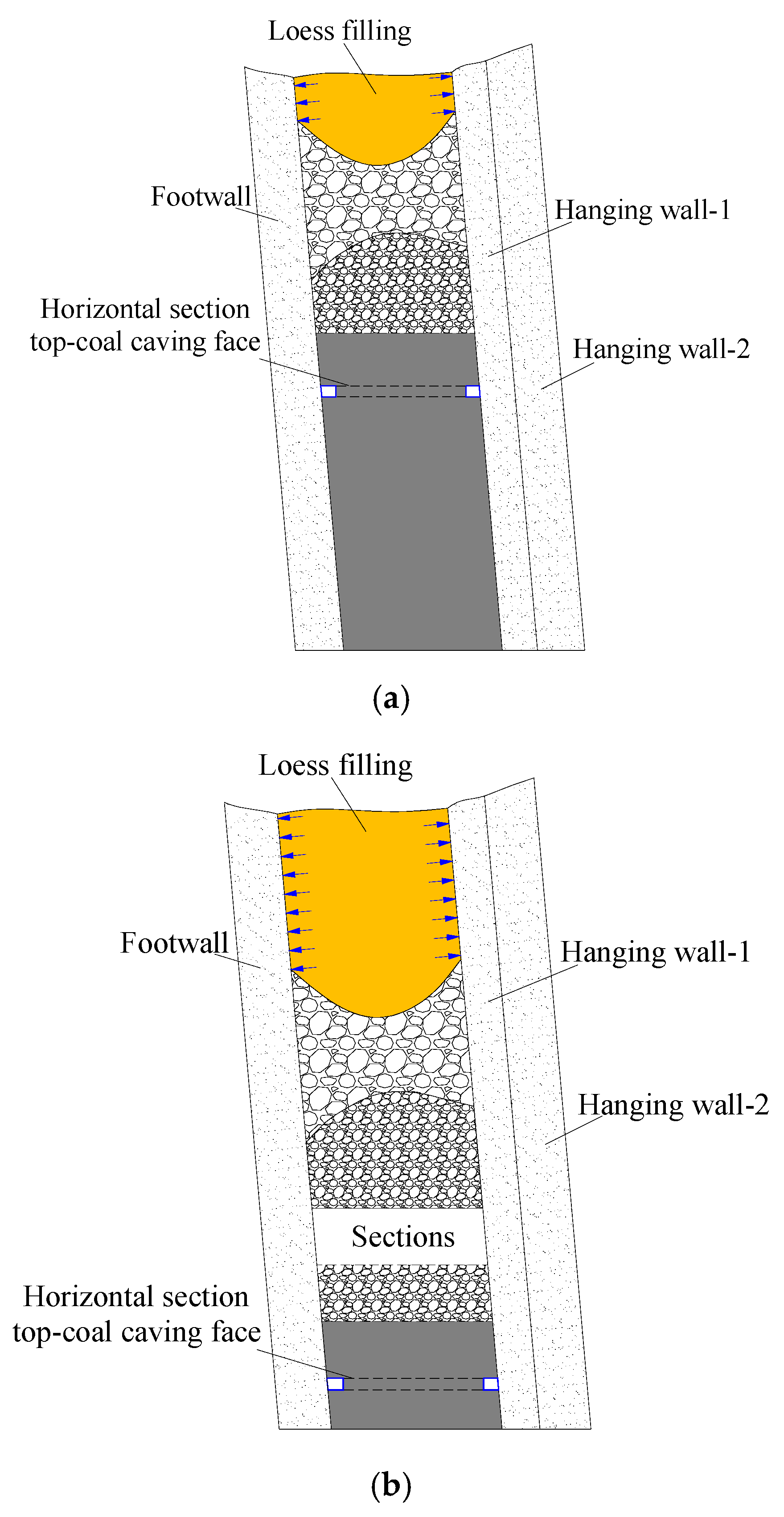
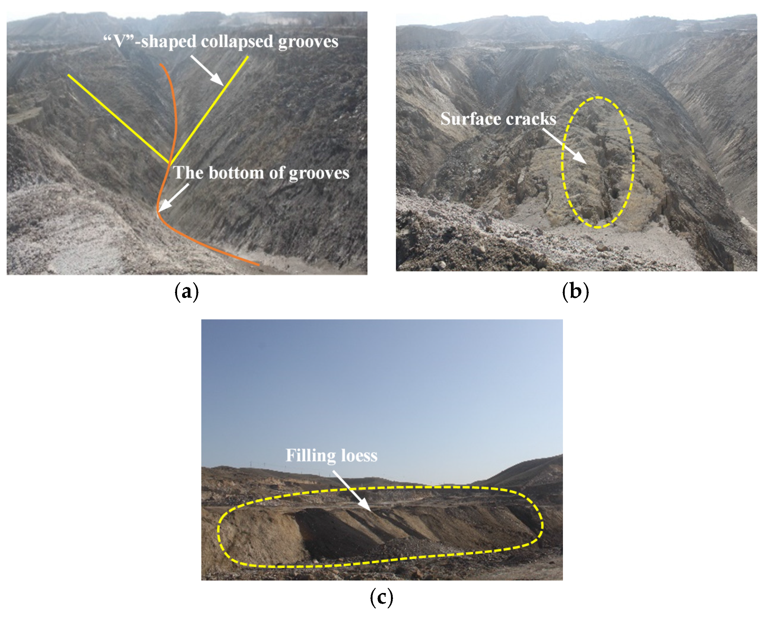
5.3. Loess Filling to Constrain Surface Collapsed Grooves

After implementation of DHB, the residual gangue above the face and the fractured hanging wall tend to collapse, resulting in subsidence of the overburden. As the vertical displacement of overburden gradually increases during mining of SDTCS, the surface over the face ultimately shows a “V”-shaped collapsed grooves. If the surface collapsed grooves were not properly treated in time, the scope of grooves would continue to expand, both vertically and horizontally. This can cause a series of problems, such as failure of the rock surrounding the grooves, landslide, spontaneous combustion of coal, and damage to local ecological system. Given the easy availability of loess across the Urumqi coalfield, loess filling was employed to control the surface “V”-shaped collapsed grooves induced by mining of the SDTCS.
Loess is granular mixture of fine clay and silt particles. With a certain bearing capacity, loess filling in the “V”-shaped collapsed grooves can apply constraint forces to the lateral surrounding rock, as shown in Figure 17. Due to its looseness and low-strength, the loess filled in the grooves showed significant deformation at the beginning. The deformation enables the loess to provide a flexible yielding support to the surrounding rock while reducing its deformation.
After a certain period of time, the loose loess consolidated into hard solid mass with improved bearing capacity. Meanwhile, the mobility of loess particles allows the fill to slide down as the grooves collapse, thereby achieving dynamic control on the surrounding rock [45,46]. The photographs of the surface after the application of loess filling are shown in Figure 18.

6. Discussion

(1)
The steeply-dipping thick seams group in the Urumqi coalfield was the product of local tectonic movements. Lateral tectonic movements exert a control role on the formation of in-situ stress. The study found that the rocks in this region are subject primarily to horizontal stresses. Therefore, the effect of tectonic stress should be considered when analyzing deformation behavior of HSTCC face’s hanging wall. In this study, a lateral pressure coefficient of 0.3 was included in the mechanical model presented above to account for the effect of tectonic stress [46].
(2)
Major factors influencing the effectiveness of DHB include blasting holes diameter, length, and space, blasting interval, etc. While blasting holes diameter and length and blasting interval depend primarily on the equipment available, geological conditions, and actual production situation, blasting holes space is easily adjustable and has a direct influence on the effectiveness of DHB in pressure relief. For this reason, the numerical analysis of the effectiveness of DHB focused on the influence of blasting holes space.
(3)
The blasting site was set right above the rear scraper conveyor behind the face, meaning that the explosive was detonated when the rear scraper conveyor reached the position under the blasting holes. In this way, the blasting energy was largely released into the goaf behind the face, thereby reducing the influence of blasting on the face as well as the headentry and tailentry along it.
(4)
The DHB technology was intended to relieve the hanging wall stress arising from hanging wall deformation after the working face was mined and thereby ensure safe production. The loess filling technology was proposed as a way to constrain surface “V”-shaped collapsed grooves resulting from SDTCS mining by HSTCC method. It uses loess to constrain the surrounding rock on the sides of the grooves area, so as to prevent rock failure and minimize ecological damage. The two technologies can be used in combination to guarantee green mining of SDTCS.

7. Conclusions

(1)
The mining process of HSTCC was simulated in this study. It was found that the hanging wall of the HSTCC face was nearly-vertical and did not fracture easily after the working face was mined. The hanging wall-1 of the HSTCC face was modeled with a clamped-clamped elastic beam model to analyze its deformation behavior. The results show that after the section 2 was mined, the maximum bending moment in the hanging wall-1 increased 8.5-fold compared with that observed after of the section 1 was mined. After the section 3 was mined, the maximum bending moment increased 29.1-fold from that observed after the section 1 was mined. These suggest that, as the mining level downwards, the bending moment in the hanging wall-1 increased and its effect on the lower-section working face grew gradually.
(2)
The pressure relief mechanism of DHB was theoretically analyzed, and its effectiveness was examined by numerical simulation. The results suggest that blasting holes space of 6 m can ensure effective weakening of hanging wall. This technology was then applied to the 4301 working face of the Jiangou coal mine. The average pressure of hydraulic supports’ legs measured at this face decreased by about 34% compared to that measured at the 4501 face, which DHB was not applied.
(3)
The loess filling technology was proposed as a way to constrain the surface “V”-shaped collapsed grooves resulting from repeated mining of SDTCS by HSTCC. The large deformation and high mobility of loess enable the loess fill in the grooves to provide constraint and dynamic control on the lateral surrounding rock. Meanwhile, this technology can be used to reduce the ecological damage caused by mining of steeply-dipping seams.

Acknowledgments

This work was supported by the National Key Basic Research Program of China (973 Program) (2015CB251600), the State Key Laboratory of Coal Resources and Safe Mining(SKLCRSM13X03), Qing Lan Project, and the Priority Academic Program Development of Jiangsu Higher Education Institutions.

Author Contributions

Jinshuai Guo proposed the innovative points and conceived; Liqiang Ma established and solved the mechanical model; Ye Wang monitored the engineering test results; Fangtian Wang performed the simulation; Jinshuai Guo and Liqiang Ma wrote the paper.

Conflicts of Interest

The authors declare no conflict of interest.

References

  1. Wu, Y.P.; Yun, D.F.; Zhang, M.F. Study on the elementary problems of full-mechanized coal mining in greater pitching seam. J. China Coal Soc. 2000, 25, 465–468. [Google Scholar]
  2. Shenxin Energy Company Has Achieve the Rapid Development of Extracting Steeply Inclined Thick Coal Seam. Available online: http://scitech.people.com.cn/n/2013/1101/c1057-23394457.html (accessed on 1 September 2017).
  3. Onica, I.; Mihailescu, V.; Andrioni, F. Economical optimization of the mechanized longwall faces with top coal caving mining, in horizontal slices. Arch. Min. Sci. 2016, 61, 651–676. [Google Scholar] [CrossRef]
  4. Tu, H.S.; Tu, S.H.; Yuan, Y.; Wang, F.T.; Bai, Q.S. Present situation of fully mechanized mining technology for steeply inclined coal seams in china. Arab. J. Geosci. 2015, 8, 4485–4494. [Google Scholar] [CrossRef]
  5. Shao, X.P.; Zhang, H.X.; Shi, P.W. Selection of reasonable section heights during top-coal caving to steep seams. J. China Univ. Min. Technol. 2009, 38, 545–549. [Google Scholar]
  6. Ju, W.J.; Li, W.Z. Fracture mechanical model of main roof along inclined for fully-mechanized top-coal caving in steep and extra-thick coal seam. J. China Coal Soc. 2008, 33, 606–608. [Google Scholar]
  7. Ma, L.Q.; Zhang, Y.; Zhang, D.S.; Cao, X.Q.; Li, Q.Q.; Zhang, Y.B. Support stability mechanism in a coal face with large angles in both strike and dip. J. S. Afr. Inst. Min. Metall. 2015, 115, 599–606. [Google Scholar] [CrossRef]
  8. Kulakov, V.N. Geomechanical conditions of mining steep coal beds. J. Min. Sci. 1995, 31, 136–143. [Google Scholar] [CrossRef]
  9. Kulakov, V.N. Stress state in the face region of a steep coal bed. J. Min. Sci. 1995, 31, 161–168. [Google Scholar] [CrossRef]
  10. Klishin, V.I.; Klishin, S.V. Coal extraction from thick flat and steep beds. J. Min. Sci. 2010, 46, 149–159. [Google Scholar] [CrossRef]
  11. Klishin, S.V.; Klishin, V.I.; Opruk, G.Y. Modeling coal discharge in mechanized steep and thick coal mining. J. Min. Sci. 2013, 49, 932–940. [Google Scholar] [CrossRef]
  12. Shi, P.W.; Zhang, Y.Z. Structural analysis of arch of spanning strata of top coal caving in steep seam. Chin. J. Rock Mech. Eng. 2006, 25, 79–82. [Google Scholar]
  13. Lai, X.P.; Sui, H.; Shan, P.F.; Qiu, H.F. Overlying strata ellipsoid-style structure of horizontal section top-coal caving in steeply inclined and extra thick coal seam. J. Min. Saf. Eng. 2014, 31, 716–720. [Google Scholar]
  14. Huang, B.X.; Liu, C.Y.; Fu, J.H.; Guan, H. Hydraulic fracturing after water pressure control blasting for increased fracturing. Int. J. Rock Mech. Min. Sci. 2011, 48, 976–983. [Google Scholar] [CrossRef]
  15. Hossain, M.M.; Rahman, M.K. Numerical simulation of complex fracture growth during tight reservoir stimulation by hydraulic fracturing. J. Pet. Sci. Eng. 2008, 60, 86–104. [Google Scholar] [CrossRef]
  16. Gao, M.F. Numedcal simulation of hard roof processing step. J. Laoning Tech. Univ. 2006, 25, 649–651. [Google Scholar]
  17. Konicek, P.; Soucek, K.; Stas, L.; Singh, R. Long-hole destress blasting for rockburst control during deep underground coal mining. Int. J. Rock Mech. Min. Sci. 2013, 61, 141–153. [Google Scholar] [CrossRef]
  18. Wang, K.; Kang, T.H.; Li, H.T.; Han, W.M. Study of control caving methods and reasonable hanging roof length on hard roof. Chin. J. Rock Mech. Eng. 2009, 28, 2320–2327. [Google Scholar]
  19. Zhang, Z.Z.; Bai, J.B.; Chen, Y.; Hao, S.P. Shallow-hole blasting mechanism and its application for gob-side entry retaining with thick and hard roof. Chin. J. Rock Mech. Eng. 2016, 35, 3008–3016. [Google Scholar]
  20. Zhang, J.X.; Zhang, Q.; Sun, Q.; Gao, R.; Germain, D.; Abro, S. Surface subsidence control theory and application to backfill coal mining technology. Environ. Earth Sci. 2015, 74, 1439–1448. [Google Scholar] [CrossRef]
  21. Sun, Q.; Zhang, J.X.; Zhang, Q.; Zhao, X. Analysis and prevention of geo-environmental hazards with high-intensive coal mining: A case study in China’s western eco-environment frangible area. Energies 2017, 10, 786. [Google Scholar] [CrossRef]
  22. Zhou, H.Q.; Hou, C.J.; Sun, X.K.; Qu, Q.D.; Chen, D.J. Solid waste paste filling for none-village-relocation coal mining. J. China Univ. Min. Technol. 2004, 33, 154–158. [Google Scholar]
  23. Qu, Q.D.; Yao, Q.L.; Li, X.H.; Rong, T.Y. Key factors affecting control surface subsidence in backfilling mining. J. Min. Saf. Eng. 2010, 26, 458–462. [Google Scholar]
  24. Zhou, Z. Research on goaf filling methods with super high-water material. J. China Coal Soc. 2010, 35, 1963–1968. [Google Scholar]
  25. Teng, H.; Xu, J.L.; Xuan, D.Y.; Wang, B.L. Surface subsidence characteristics of grout injection into overburden: Case study of Yuandian No. 2 coalmine, China. Environ. Earth Sci. 2016, 75, 530. [Google Scholar] [CrossRef]
  26. Zhu, W.B.; Xu, J.L.; Lai, W.Q.; Wang, Z.G. Research of isolated section-grouting technology for overburden bed separation space to reduce subsidence. J. China Coal Soc. 2007, 32, 458–462. [Google Scholar]
  27. Zhang, D.S.; Liu, H.L.; Fan, G.W.; Wang, X.F. Connotation and prospection on scientific mining of large Xinjiang coal base. J. Min. Saf. Eng. 2015, 32, 1–6. [Google Scholar]
  28. Shao, X.P.; Shi, P.W. Strata behavior in large section face of steep seams. J. Min. Saf. Eng. 2009, 26, 36–40. [Google Scholar]
  29. Wang, N.B.; Zhang, N.; Cui, F.; Cao, J.T.; Lai, X.P. Characteristics of stope migration and roadway surrounding rock fracture for fully-mechanized top-coal caving face in steeply dipping and extra-thick coal seam. J. China Coal Soc. 2013, 38, 1312–1318. [Google Scholar]
  30. Lai, X.P.; Li, Y.P.; Wang, N.B.; Liu, Y.H.; Ran, P.J. Roof deformation characteristics with full-mechanized caving face based on beam structure in extremely inclined coal seam. J. Min. Saf. Eng. 2015, 32, 871–876. [Google Scholar]
  31. Zhang, J.W.; Wang, J.A. Energy distribution characteristics and rock burst control methods of steeper inclined thick coal seam hanging roof. J. China Coal Soc. 2014, 39, 316–324. [Google Scholar]
  32. Shi, P.W.; Shao, X.P. Function of destruction and instability of basic roof in top coal caving of steep seams. J. Liaoning Tech. Univ. 2006, 25, 325–328. [Google Scholar]
  33. Lai, X.P.; Sun, H.; Shan, P.F.; Cai, M.; Cao, J.T.; Cui, F. Structure instability forecasting and analysis of giant rock pillars in steeply dipping thick coal seams. Int. J. Miner. Metall. Mater. 2015, 22, 1233–1244. [Google Scholar] [CrossRef]
  34. Ma, L.Q.; Cao, X.Q.; Li, Q.Q.; Jia, J.L.; Fan, G.W. The support stability mechanism in dip direction of fully mechanised working face with big dip angle considering the strike angle. Int. J. Oil Gas Coal Technol. 2015, 9, 61–78. [Google Scholar] [CrossRef]
  35. Huang, Y.L.; Li, J.M.; Song, T.Q.; Kong, G.Q.; Li, M. Analysis on filling ratio and shield supporting pressure for overburden movement control in coal mining with compacted backfilling. Energies 2017, 10, 31. [Google Scholar] [CrossRef]
  36. Chen, J.; Du, J.P.; Zhang, W.S.; Zhang, J.X. An elastic base beam model of overlying strata movement during coal mining with gangue back-filling. J. China Univ. Min. Technol. 2012, 41, 14–19. [Google Scholar]
  37. Yang, J.X.; Liu, C.Y.; Yang, P.J.; Yang, Y. Research on roadside packing technology for end zone of steep inclined coal seam face. Rock Soil Mech. 2014, 35, 543–550. [Google Scholar]
  38. Cui, F.; Lai, X.P.; Cao, J.Y. Mining disturbance of horizontal section full-mechanized caving face in steeply inclined coal seam. J. Min. Saf. Eng. 2015, 32, 610–616. [Google Scholar]
  39. Sanchidrián, J.A.; Segarra, P.; López, L.M. Energy components in rock blasting. Int. J. Rock Mech. Min. Sci. 2007, 44, 130–147. [Google Scholar] [CrossRef]
  40. Wang, F.T.; Tu, S.H.; Yuan, Y.; Feng, Y.F.; Chen, F.; Tu, H.S. Deep-hole pre-split blasting mechanism and its application for controlled roof caving in shallow depth seams. Int. J. Rock Mech. Min. Sci. 2013, 64, 112–121. [Google Scholar] [CrossRef]
  41. Shang, X.J.; Su, J.Y. Dynamic Analysis Method and Engineering Example of Ansys/Ls-Dyna; China Water Conservancy and Hydropower Press: Beijing, China, 2008. [Google Scholar]
  42. Shi, S.Q.; Kang, J.G.; Wang, M.; Liu, Y.; Li, X.D. The Engineering Applications of Ansys/ls-Dyna in the Field of Explosion and Impact; China Construction Industry Press: Beijing, China, 2011. [Google Scholar]
  43. Gao, K.; Liu, Z.G.; Liu, J.; Deng, D.S.; Gao, X.Y.; Kang, Y.; Huang, K.F. Application of deep borehole blasting to gob-side entry retaining forced roof caving in hard and compound roof deep well. Chin. J. Rock Mech. Eng. 2013, 32, 1588–1594. [Google Scholar]
  44. Liu, Z.; Cao, A.; Zhu, G.; Wang, C. Numerical simulation and engineering practice for optimal parameters of deep-hole blasting in sidewalls of roadway. Arab. J. Sci. Eng. 2017, 42, 3809–3818. [Google Scholar] [CrossRef]
  45. Shao, X.P.; Shi, P.W. Stability research of surrounding rock at gob area using large section mining in steep seam. J. Liaoning Tech. Univ. (Nat. Sci.) 2010, 29, 353–356. [Google Scholar]
  46. Lai, X.-P.; Cai, M.-F.; Ren, F.-H.; Shan, P.-F.; Cui, F.; Cao, J.-T. Study on dynamic disaster in steeply deep rock mass condition in urumchi coalfield. Shock Vib. 2015, 2015, 465017. [Google Scholar] [CrossRef]
Figure 1. Distribution of Urumqi coal field and major coal mines.
Energies 10 01371 g001
Figure 2. Distribution of coal seams in the Jiangou coal mine. (B1–2 and B3–6 in the figure represent 45# and 43# coal seam respectively).
Energies 10 01371 g002
Figure 3. Stratigraphic column of the 4301 working face.
Energies 10 01371 g003
Figure 4. Layout of HSTCC face. (a) Along-strike profile; and (b) Along-dip profile.
Energies 10 01371 g004
Figure 5. HSTCC numerical simulation model.
Energies 10 01371 g005
Figure 6. HSTCC numerical simulation results. (a) After the section 1 was mined; (b) After the section 2 was mined; (c) After the section 3 was mined.
Energies 10 01371 g006
Figure 7. Distribution of hanging wall-1 stress during mining. (a) Horizontal stress distribution; (b) Vertical stress distribution.
Energies 10 01371 g007
Figure 8. Mechanical model of the HSTCC face’s hanging wall-1. (a) Rock pressure model; (b) Mechanical mode; (c) Bending moment distribution.
Energies 10 01371 g008
Figure 9. Bending moment distribution of the hanging wall-1.
Energies 10 01371 g009
Figure 10. DHB numerical simulation model.
Energies 10 01371 g010
Figure 11. Effective stress contours after blasting. (a) 1.19E+02 μs; (b) 5.39E+02 μs; (c) 9.00E+02 μs; (d) 1.38E+03 μs.
Energies 10 01371 g011aEnergies 10 01371 g011b
Figure 12. Variation in effective stress with the distance from the blasting hole.
Energies 10 01371 g012
Figure 13. Layout of blasting hole. (a) Plan of the blasting hole; (b) Profile of the blasting hole; and (c) Detail structure of blasting hole.
Energies 10 01371 g013
Figure 14. Practical application of DHB at the 4301 working face. (a) Blasting hole drilling; (b) Blasting hole charging; (c) Residual hole after blasting.
Energies 10 01371 g014
Figure 15. Location of the 4301 and 4501 working face.
Energies 10 01371 g015
Figure 16. Pressure of hydraulic legs change during advance of the working face.
Energies 10 01371 g016
Figure 17. Schematic of surface loess filling. (a) After shallow sections mined; (b) After deep sections mined.
Energies 10 01371 g017
Figure 18. Practical application of surface loess filling. (a) “V”-shaped collapsed grooves; (b) Surface cracks; (c) Surface after loess filling.
Energies 10 01371 g018
Table 1. Rock physical and mechanical parameters (block).
NumberStrataThickness (m)Density (kg/m3)Bulk Modulus (GPa)Shear Modulus (GPa)Cohesion (MPa)Friction Angle (°)Tensile Strength (MPa)
1Footwall30253010.88.12.8383.1
243# coal seam5614002.91.31.2282.0
3Hanging wall-18253010.88.12.8383.1
4Hanging wall-256253010.88.12.8383.1
Table 2. Rock physical and mechanical parameters (contact).
NumberStrataThickness (m)Normal Stiffness (GPa)Shear Stiffness (GPa)Cohesion (MPa)Friction Angle (°)Tensile Strength (MPa)
1Footwall3030102.5305
243# coal seam561581.0203
3Hanging wall-1830102.5305
4Hanging wall-25630102.5305

