Performance Investigation of the Novel Solar-Powered Dehumidification Window for Residential Buildings

1
School of Civil and Transportation Engineering, Guangdong University of Technology, Guangzhou 510006, China
2
School of Engineering, University of Hull, Hull HU6 7RX, UK
*
Author to whom correspondence should be addressed.
Energies 2017, 10(9), 1369; https://doi.org/10.3390/en10091369
Submission received: 19 July 2017
/
Revised: 3 September 2017
/
Accepted: 5 September 2017
/
Published: 10 September 2017
(This article belongs to the Special Issue Solar Technologies for Buildings)
Abstract
:In this paper, a solar-powered dehumidification window (SPDW), combining a conventional double-glazed building window with a solid desiccant packed bed and a photovoltaic panel, has been proposed to dehumidify the air supplied to a residential building in an energy-saving way. The solid desiccant packed bed was installed between the double layers of the residential window to achieve the compact building-integrated window-dehumidifying system that could be regenerated by solar energy, and the photovoltaic panel was used to compensate the electricity for the operation of the fans to supply the air to the building. To investigate the dehumidification and regeneration performance of the SPDW, the transient moisture removal, dehumidification efficiency, temperature difference between the building inlet and outlet air, heat transfer characteristics, desiccant temperature, regeneration rate, and the power of the fans and the photovoltaic panel were analysed for different inlet air conditions and simulated solar radiation. It was found that, for the system operated under an inlet air temperature of 19.2 °C and a relative humidity of 86.1% during the dehumidification process, the system performed with a maximum transient moisture removal of 7.1 g/kg, a maximum dehumidification efficiency of 58.60%, a maximum temperature difference between the inlet and outlet air of 10.7 °C, and a maximum released adsorption heat absorbed by the dehumidified air of 89.66%. In the regeneration process, the system performed with a maximum desiccant temperature of 35.3 °C, a maximum regeneration rate of 153 g/h, and a maximum power of the photovoltaic panels of 39.83 W under the simulated solar radiation of 900 W/m2. The results from the established semi-empirical model agreed well with the testing results, and the model could be used to predict the water content ratio of the desiccant modules during the dehumidification process under different conditions, which will be helpful in the analysis and application of the SPDW in the future.
1. Introduction
Nowadays, energy crisis is one of the main problems faced by the whole world, and the building sector is one of the largest energy end-use sectors that consume more than 40% of the global energy [1,2]. In particular, over half of the energy consumed by a building is contributed by the conventional vapour compression cooling system for indoor air conditioning due to its air process of excess cooling and reheating [3]. A suitable alternative to this energy-intensive system is called the solid desiccant cooling system [4], which integrates a solid desiccant device with an evaporative cooling system to realize air humidity and temperature independent control for resolving the problems of excess cooling and reheating. According to the configured methods, the solid desiccant devices of the solid desiccant cooling system can be divided into the fluidized bed, the rotary desiccant wheel, and the solid desiccant packed bed. The fluidized bed has a lower pressure drop than the packed bed, but it might create dust pollution by the collision between particles [5]. The rotary desiccant wheel is widely adopted in the solid desiccant cooling system, but it was found that the adsorption heat from the desiccant dehumidification greatly lowered its performance because it was difficult to remove the heat by an inner-cooling process due to the structure of the rotary wheel [6,7]. Since the solid desiccant packed bed performs without dust pollution and since it is relatively easy to realize an inner-cooling dehumidification process to remove the adsorption heat, the solid desiccant packed bed has received much attention for application in a solid desiccant cooling system [8,9].
Over the past few years, a number of investigations have been conducted on solid desiccant packed beds. Kabeel [10] studied the effect of the design parameters on the performance of a multilayer desiccant packed bed. Awad et al. [11] designed a radial flow hollow cylindrical packed bed for reducing the distance travelled by the air through the vertical bed, and the maximum value of the mass transfer coefficient was 2.2 kg/m3. An intercooled desiccant packed bed was proposed by Ramzy et al. [12], and a 22% increase in the total adsorbed mass was achieved in comparison with the conventional packed beds. A cross-cooled desiccant packed bed was proposed by Yuan et al. [13], and the simulation results indicated that the dehumidification efficiency reached 12.4%. Ge et al. [14,15] concluded that the air-liquid heat exchanger had a higher heat transfer coefficient than the air-to-air heat exchanger and consequently removed more adsorption heat. Peng et al. [16] proposed a desiccant-coated packed bed by coating desiccant material to the outside surface of the conventional fin-tube heat exchangers, and the moisture removal could reach 43.8%. Wang et al. [17] improved the desiccant-coated packed bed by combining the regenerative evaporative cooler, and they found that the average moisture removal of the packed bed with regenerative evaporative cooler was 17% higher than that of the packed bed without regenerative evaporative cooler. It can be seen that most of the investigations focus on optimizing the structure and improving the adsorption capacity of the solid desiccant packed bed. However, as the treated air increases, the application of the packed bed in a solid desiccant cooling system will require more space and energy.
In order to reduce the space and energy the packed bed requires, the novel solar-powered dehumidification window (SPDW), integrating the double-glazed window of the building with the desiccant packed bed and photovoltaic (PV) panel, is proposed in this paper. The SPDW can dehumidify the air supplied to the residential building, and the electric energy the SPDW needs can be compensated by the PV panel. Moreover, the saturated solid desiccant of the SPDW can be regenerated from the solar energy. In order to investigate the dehumidification and regeneration performance of the proposed system, the testing rig of the SPDW was constructed at the laboratory of the Guangdong University of Technology (Guangzhou, China) and tested under different conditions of inlet air and simulated solar radiation. The experimental results will be used to verify the semi-empirical model for the prediction of the water content ratio of the solid desiccant modules by applying the isothermal adsorption assumption during the dehumidification process. This research will be helpful in introducing energy-saving and building-integrated dehumidification technology, realising the global target of decreasing buildings’ energy consumption, and indicating potential research areas for the researchers.
2. System Description
The proposed SPDW was composed of a PV panel, flat-plate glass cover, fans, orifice plates, double shutters, and desiccant modules filled with solid desiccant (i.e., silica gel), as shown in Figure 1.
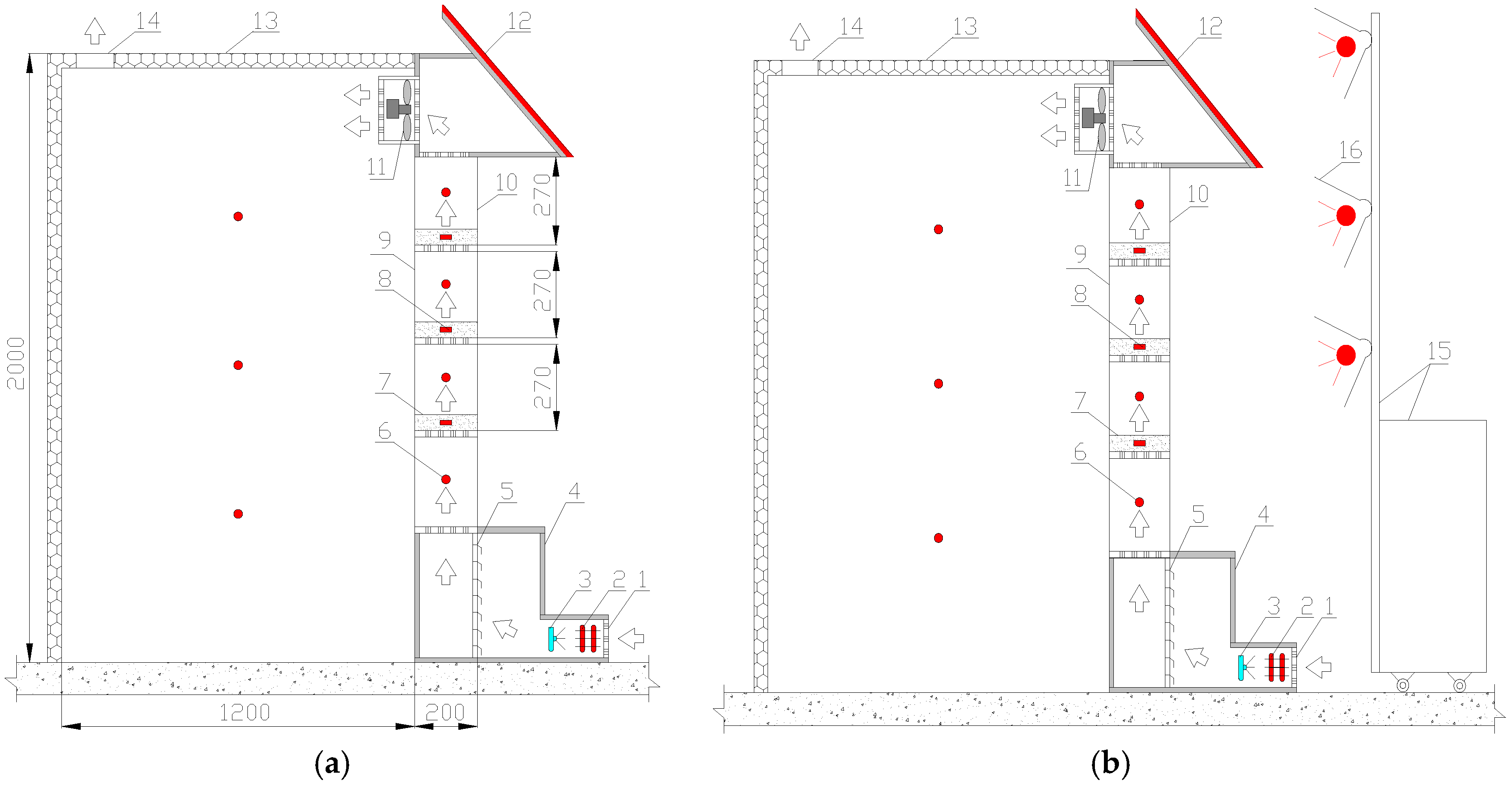
The proposed window will operate under two modes, i.e., dehumidification and regeneration processes, as shown in Figure 1a,b. In the dehumidification process, the fans inside the window will operate, while the fans on both sides of the window will be shut down. The outdoor air will enter into the window from the air inlet, be dehumidified when it passes through the solid desiccant modules, and be pumped into the building through the fans inside the window. In the regeneration process, the fans on both sides of the window will operate, while the fans inside the window will be shut down. Hence, the outdoor air will enter into the window from the air inlet, take away the vapour evaporating from the solid desiccant modules due to the regeneration from the solar radiation, and be discharged to the surroundings through the fans on both sides of the window. It can be predicted that the interference of the moist air exhaust with the outdoor air inlet will be small because the temperature of the exhaust air will be higher than that of the ambient air, and the exhaust air will move upward. Moreover, the airflow flux of the window will be small to allow the ambient airflow to carry away the exhaust air. Also, there will be no fogging on the upper level fenestration near the moist air exhaust because the temperature of fenestration will be raised due to the adsorption of solar radiation. During these processes, the electric energy consumed by the fans can be compensated by the photovoltaic panel.
The novelty of the SPDW could be summarised as follows: (1) The SPDW can be potentially used to replace the existing residential building window, which can not only save the construction materials but also reduce the space that the solid desiccant packed bed and PV panel need. This could be helpful to realise the building integration of the proposed system component. (2) Solar radiation can be used to regenerate the solid desiccant and drive the fans to a certain extent, which can significantly increase the energy efficiency of the window and eventually reduce the energy consumption of the air conditioning.
3. Construction of the Testing Rig
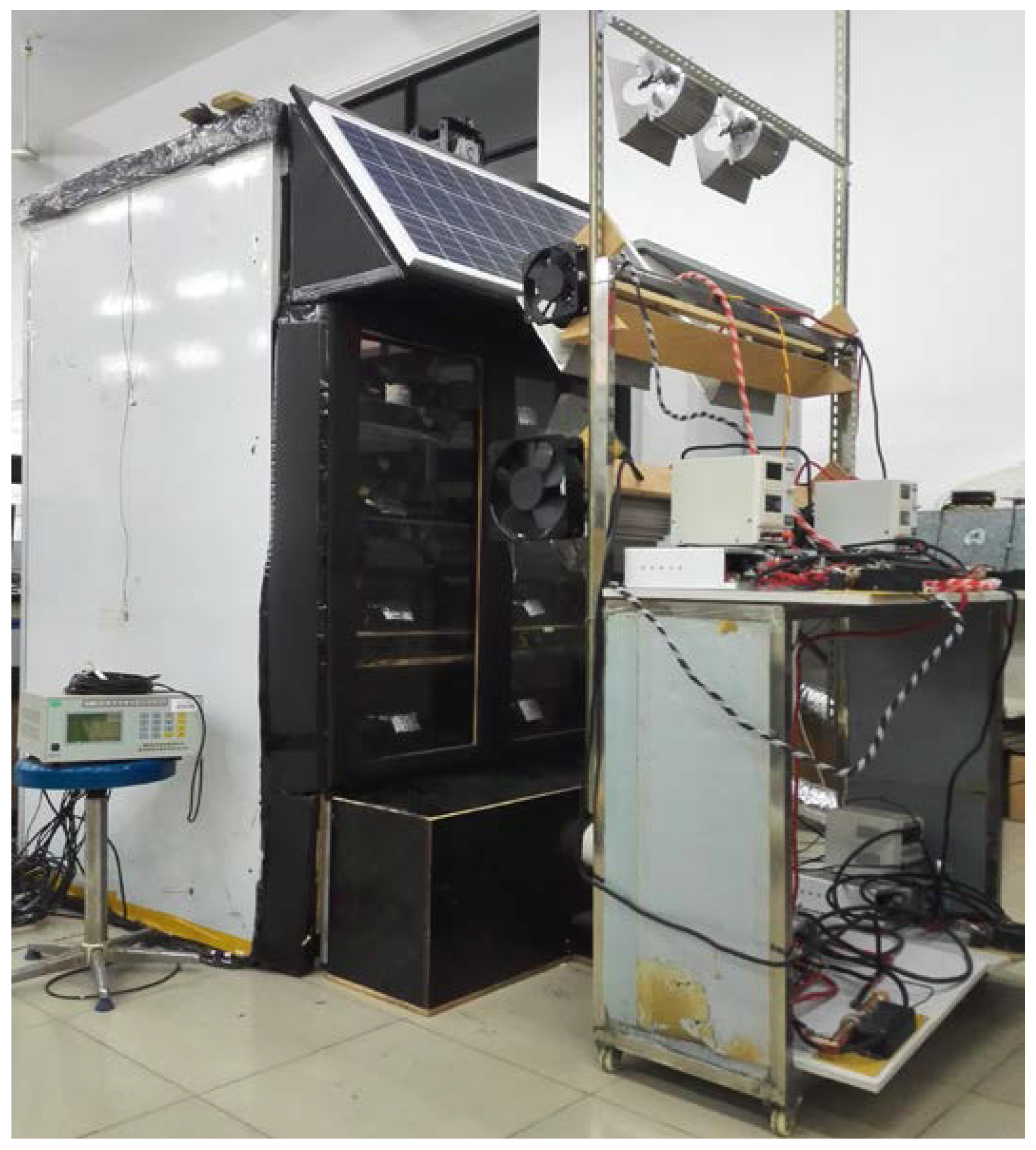
In order to investigate the dehumidification and regeneration performance of the SPDW, the SPDW was designed with a total flat-plate glass area of 1 m2. The testing rig of the proposed SPDW and the images of the testing rig are shown in Figure 2, Figure 3, Figure 4 and Figure 5. The parameters of the experimental material, apparatuses, and instruments are presented in Table 1.
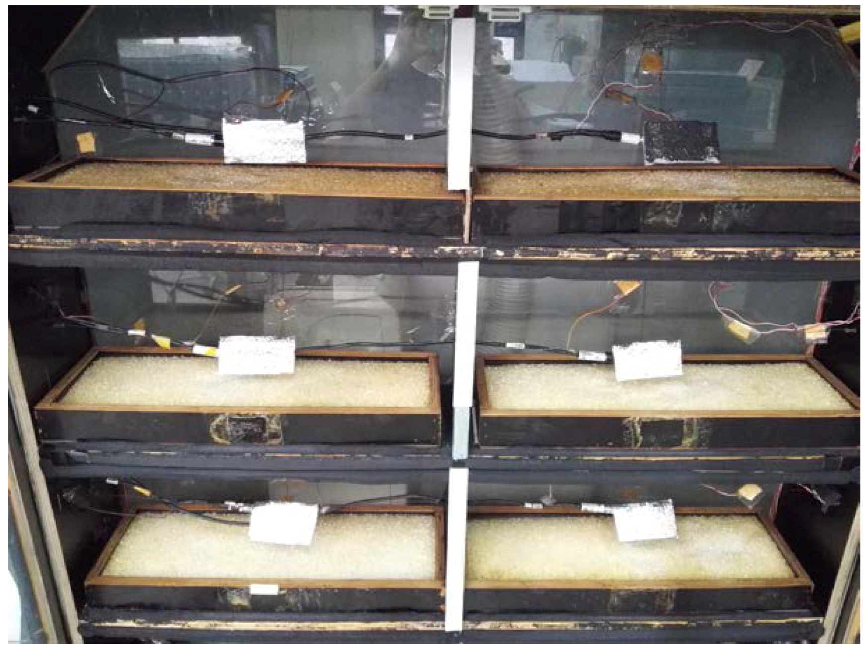
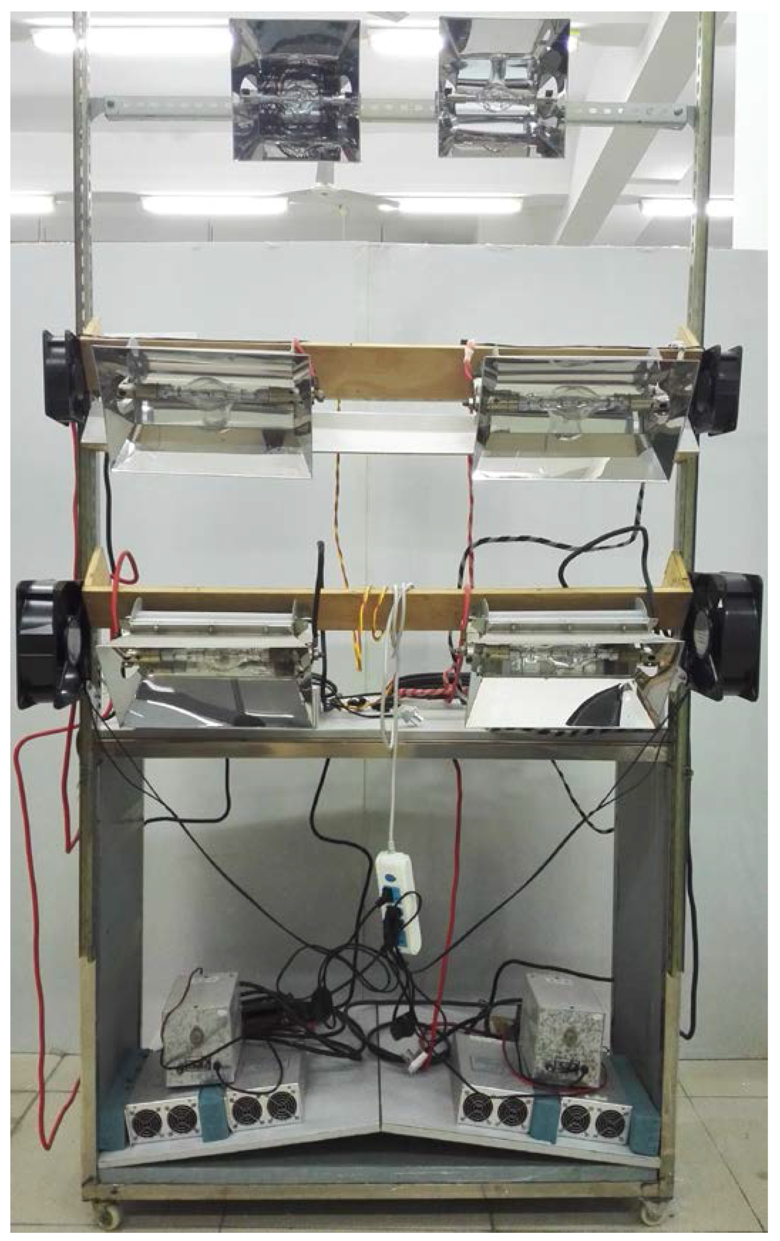
The testing rig of the SPDW was composed of the mixing chamber, solid desiccant modules, ordinary window glass, fans, testing space, PV panel, and xenon lamps. The outdoor air was pretreated in the mixing chamber, where the temperature and humidity of the inlet air were controlled using the electric heater and the ultrasonic humidifier. The six desiccant modules, each filled with 3 kg silica gel and having the same size of 550 mm in length, 190 mm in width, and 50 mm in thickness, were used to dehumidify the air. The distance between each two desiccant modules was at 290 mm. The desiccant modules were fit into the 3 mm space between the two layers of the ordinary window glass. The inside layer of the window glass was fixed, while the outside layer was movable for conveniently replacing the saturated desiccant modules. Two fans were installed above the solid desiccant modules to drive the outdoor air into the testing space. The testing space of 1250 mm × 1200 mm × 2000 mm was made of colour-coated steel insulation panels of 50 mm thickness, representing the an indoor room of the building, where the temperature and relative humidity of the air were measured every hour for analysis. The PV panel, which was 1150 mm in length and 500 mm in width, was made of polycrystalline silicon cells and installed on the sunblind. For the evenness of the simulated solar energy, four xenon lamps were used to simulate sunlight of different radiations during the regeneration mode by regulating the input voltage of the lamps. Also, two xenon lamps were used to simulate the sunlight for the PV panel, and the simulated radiations were recorded by the pyranometer.
4. Methods
In order to investigate the dehumidification and regeneration performance of the SPDW, the transient moisture removal, dehumidification efficiency, heat transfer characteristics, and regeneration rate were defined for the system operated under different inlet air conditions and simulated solar radiations.
The dehumidification efficiency of the solid desiccant modules η was determined as the ratio of the transient moisture removal to the humidity ratio of the inlet airflow, as in Equation (2) [19].
The heat transfer characteristics referred to the distribution of the released adsorption heat Ql during the dehumidification process. The Ql could be considered as the condensation heat of the water vapour in the SPDW and divided into three parts: (1) the heat absorbed by the dehumidified air Qa; (2) the heat absorbed by the solid desiccant modules Qs; and (3) the heat losses from the window to the surrounding Qd. The relationships between the four parameters during the heat transfer processes of the SPDW is shown in Equations (3) to (6) [20,21].
The regeneration rate of the solid desiccant modules Rc was determined as the product of the mass flow rate and the humidity ratio difference between the inlet and outlet air of the SPDW, as in Equation (7) [22].
5. Analysis and Discussion of the Testing Results
Experiments on the dehumidification and regeneration processes of the SPDW will be conducted, and the testing results will be analysed and discussed respectively for the investigation of the dehumidification and regeneration performance of the SPDW. It should be mentioned that the basis for choosing the air conditions was the typical hot and humid weather (from March to May) in southern China (Guangzhou), wherein the air temperature and relative humidity ranged from 18 to 26 °C and from 70% to 85%, respectively.
5.1. Analysis and Discussion of the Testing Results of Dehumidification Process
In order to investigate the dehumidification performance of the SPDW, five inlet air conditions will be investigated during the tests, as shown in Table 2. Four evaluation indicators, i.e., the transient moisture removal, dehumidification efficiency, temperature difference between the inlet and outlet air of the window and heat transfer characteristics, will be analysed for the system operated under different inlet air conditions.
5.1.1. Transient Moisture Removal
Figure 6 indicates the time variation of the transient moisture removal of the solid desiccant modules during the dehumidification process at different inlet air temperatures and relative humidities. It was found that the solid desiccant modules had the maximum transient moisture removal at 7.1 g/kg, when the inlet air temperature was at 19.2 °C and the relative humidity was at 86.1%. It was also found that the transient moisture removal reached its maximum at the beginning of the dehumidification process due to the least accumulation of water content and adsorption heat in the modules. Moreover, it decreased sharply in the first three hours and then slowly due to the increase of the water content in the modules, indicating that the window could maintain a relatively high humidity adsorption capacity for more than three hours.
For the window operated under the same inlet air temperature, the transient moisture removal increased with the increase of the relative humanity of the inlet air due to the increase of the vapour pressure difference between the air and the solid desiccant. As to the window operated under the same relative humidity as the inlet air, the transient moisture removal decreased with the increase of the inlet air temperature because of the decrease in heat transfer from the solid desiccant to the dehumidified air, resulting in heat accumulation in the solid desiccant and consequently reducing the adsorption capacity of the window.
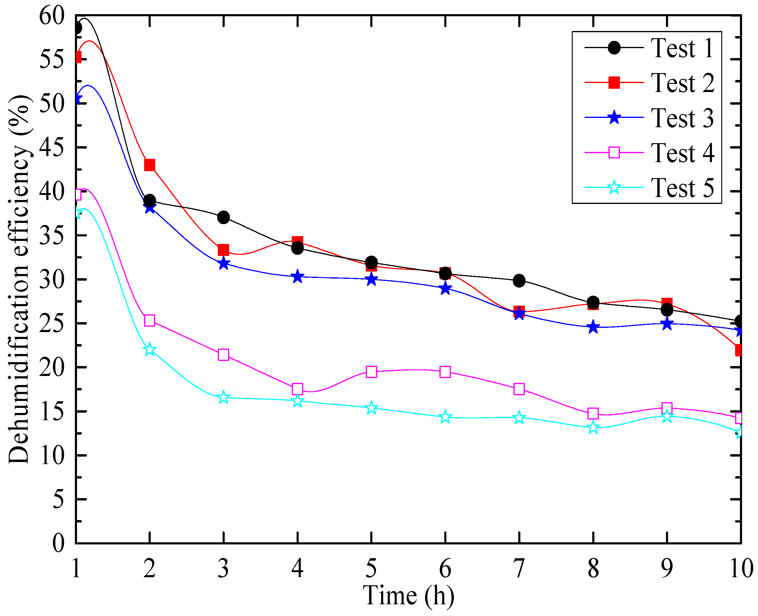
5.1.2. Dehumidification Efficiency
Figure 7 shows the variation of dehumidification efficiency with time under different inlet air conditions. From Figure 7, it can be found that the dehumidification efficiency of the solid desiccant modules decreased during the testing period that the maximum values appeared at the beginning of the testing. It could also be observed that the system performed better under higher inlet air relative humidity and lower inlet air temperature conditions. The maximum of the solid desiccant modules’ dehumidification efficiency could be found at 58.60%, which corresponded to the inlet air temperature of 19.2 °C and a relative humidity of 86.1%. Meanwhile, the average dehumidification efficiency of this test was 33.96%.
5.1.3. Temperature Difference between the Inlet and Outlet Air
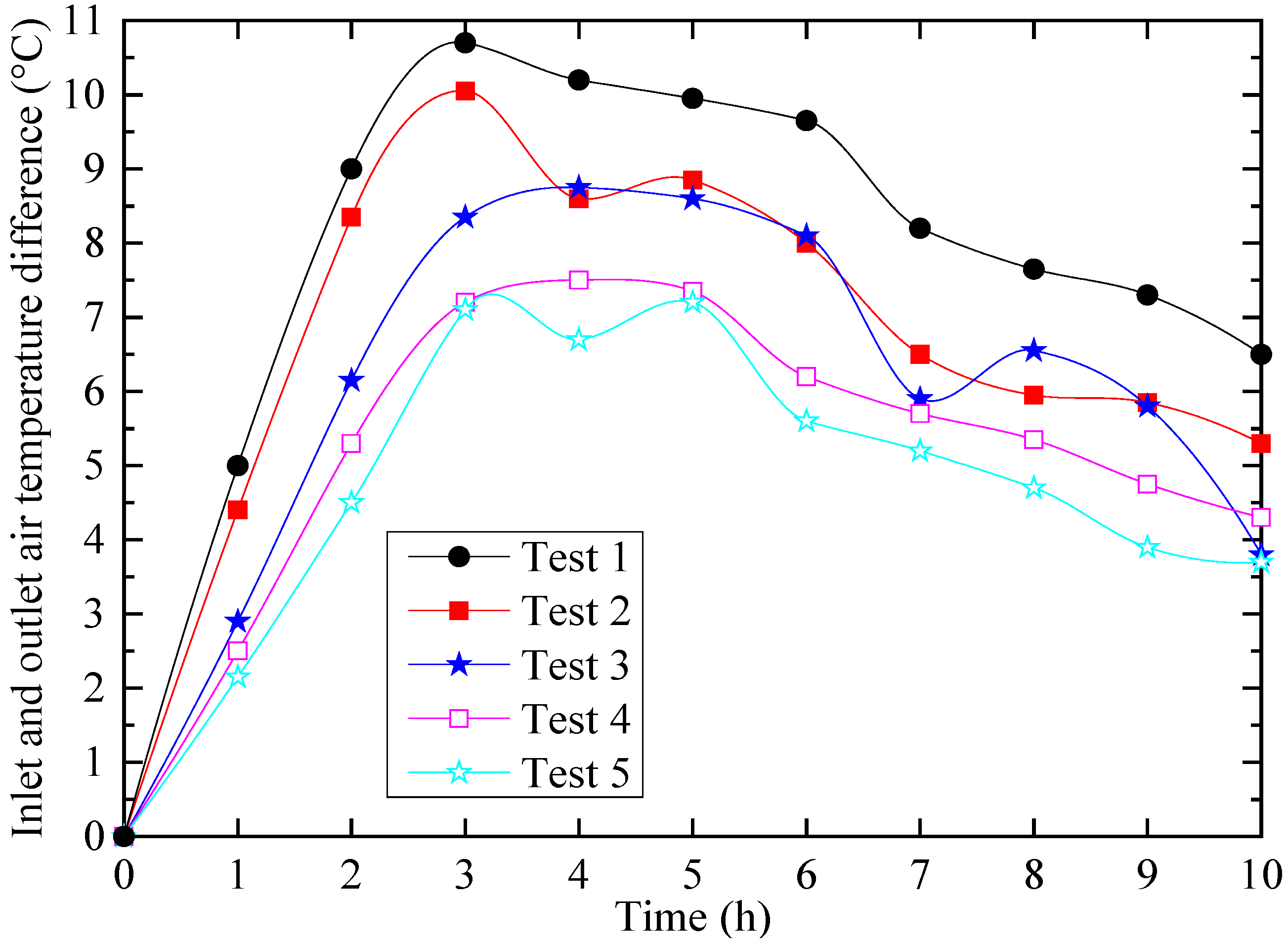
The air temperature was raised when the air passed through the desiccant in the dehumidification process, and the temperature difference between the inlet and outlet air had significant influence on the sensible cooling load of the air conditioning. Figure 8 presents the time variation of the inlet and outlet air temperature difference, and Table 3 and Table 4 indicate the temperature rise of the dehumidified air and the solid desiccant.
From above figure and tables, it can be seen that the air temperature difference increased significantly in the first three hours, reaching the maximum values of 10.7 °C, 10.1 °C, 8.8 °C, 7.7 °C, and 6.4 °C for the five tests, and then decreased gradually. A delay of one or two hours could be found between the maximum temperature difference of the air and the temperature rise of the silica gel because the adsorption heat was firstly absorbed by the solid desiccant and then to the dehumidified air. The air temperature difference was also found to increased with the increase of the relative humidity of the inlet air and the decrease of the inlet air temperature.
5.1.4. Heat Transfer Characteristics
The results of the heat transfer characteristics during the dehumidification process are listed in Table 5. It can be seen that most of the adsorption heat (more than 80%) was absorbed by the dehumidified air, while only a small part (less than 20%) was transferred to the solid desiccant or dissipated to the surroundings, consequently resulting in an increase in the dehumidified air temperature and the sensible cooling load of the air conditioning. Hence, it is necessary to take measures, e.g., introducing cooled water by intercooling channels, to reduce the dehumidified air temperature in the dehumidification process for energy-saving purposes.
5.2. Analysis and Discussion of the Testing Results of Regeneration Process
The regeneration experiment was conducted after the solid desiccant was saturated. In order to investigate the regeneration performance of the SPDW, three conditions of simulated solar radiation, i.e., 300 W/m2, 600 W/m2, and 900 W/m2, will be conducted under an inlet air temperature of 24.5 °C and a relative humidity of 80%. The variation of the desiccant temperature and the regeneration rate with time [23,24] will be analysed for the system operated under different simulated solar radiations.
5.2.1. Desiccant Temperature
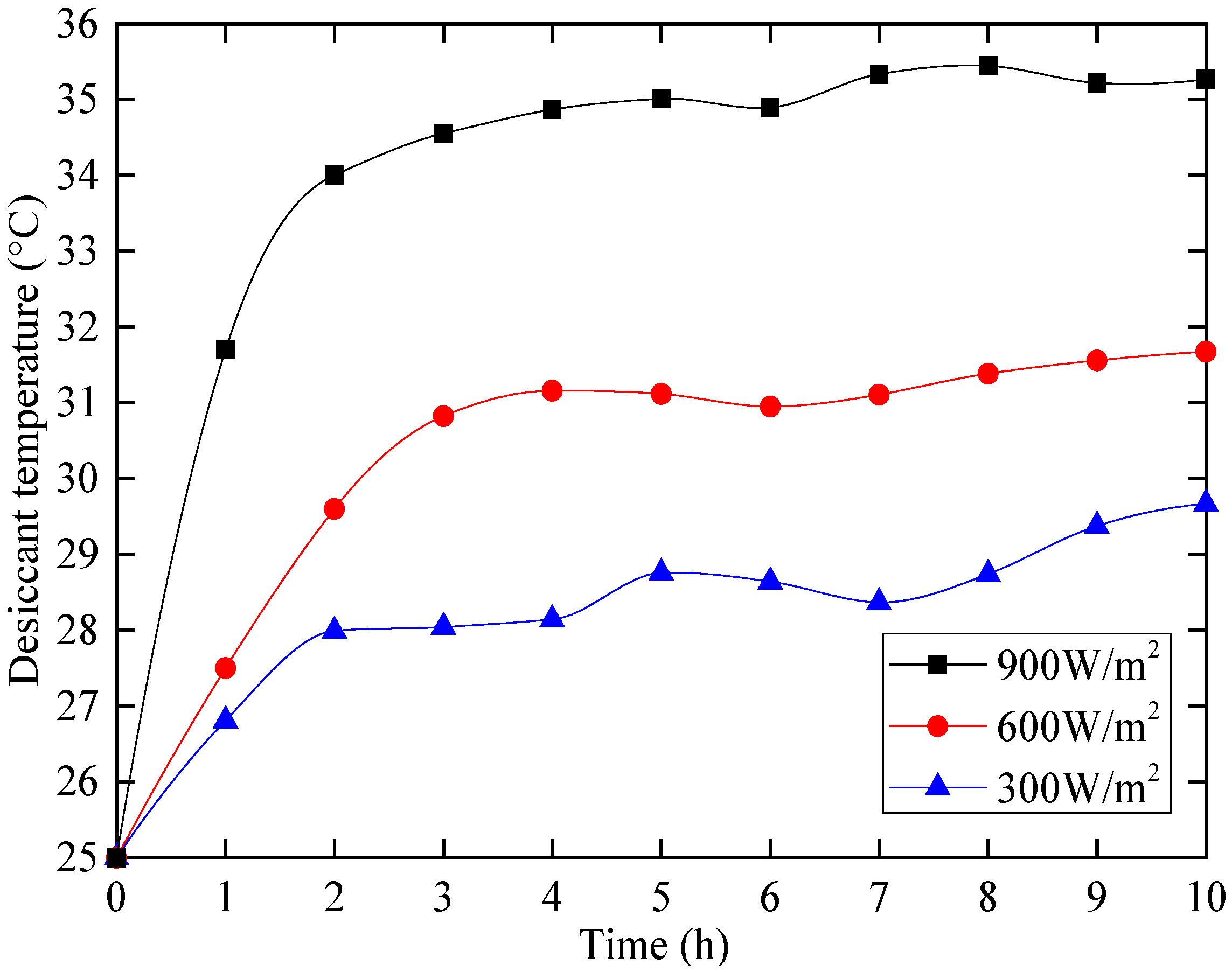
The desiccant temperature was raised due to the adsorption of simulated solar radiation during the regeneration process, and the time variation of the desiccant temperature is shown in Figure 9.
From Figure 9, it was found that the desiccant temperature increased significantly in the first two hours and then gradually. This was because the temperature difference between the desiccant and the process air was initially small and then became large, resulting in large heat loss from the desiccant to the process air. The maximum desiccant temperatures were found to be 35.3 °C, 31.7 °C, and 29.7 °C corresponding to the simulated solar radiations of 900 W/m2, 600 W/m2, and 300 W/m2, respectively. The desiccant temperature increased with the increase of simulated solar radiation.
5.2.2. Regeneration Rate
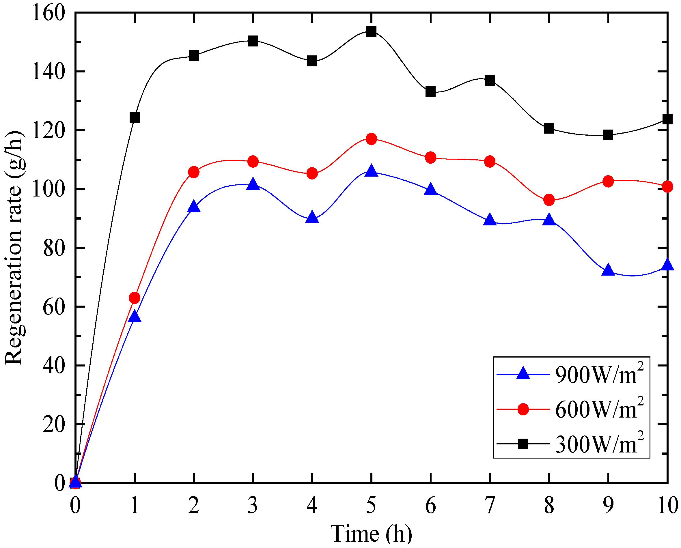
Figure 10 shows the time variation of the regeneration rate of the solid desiccant modules during the regeneration process. It can be observed that the regeneration rate first increased sharply due to an increase in the desiccant temperature and then decreased gradually due to the decrease in the moisture content in the desiccant. The maximum values of the regeneration rate reached 153 g/h, 117 g/h, and 106 g/h under simulated solar radiations of 900W/m2, 600W/m2, and 300W/m2, respectively. It was also found that the regeneration rate of the solid desiccant modules increased with the increase of the simulated solar radiation.
5.3. Analysis and Discussion of the Testing Results of the Fans and PV Panel
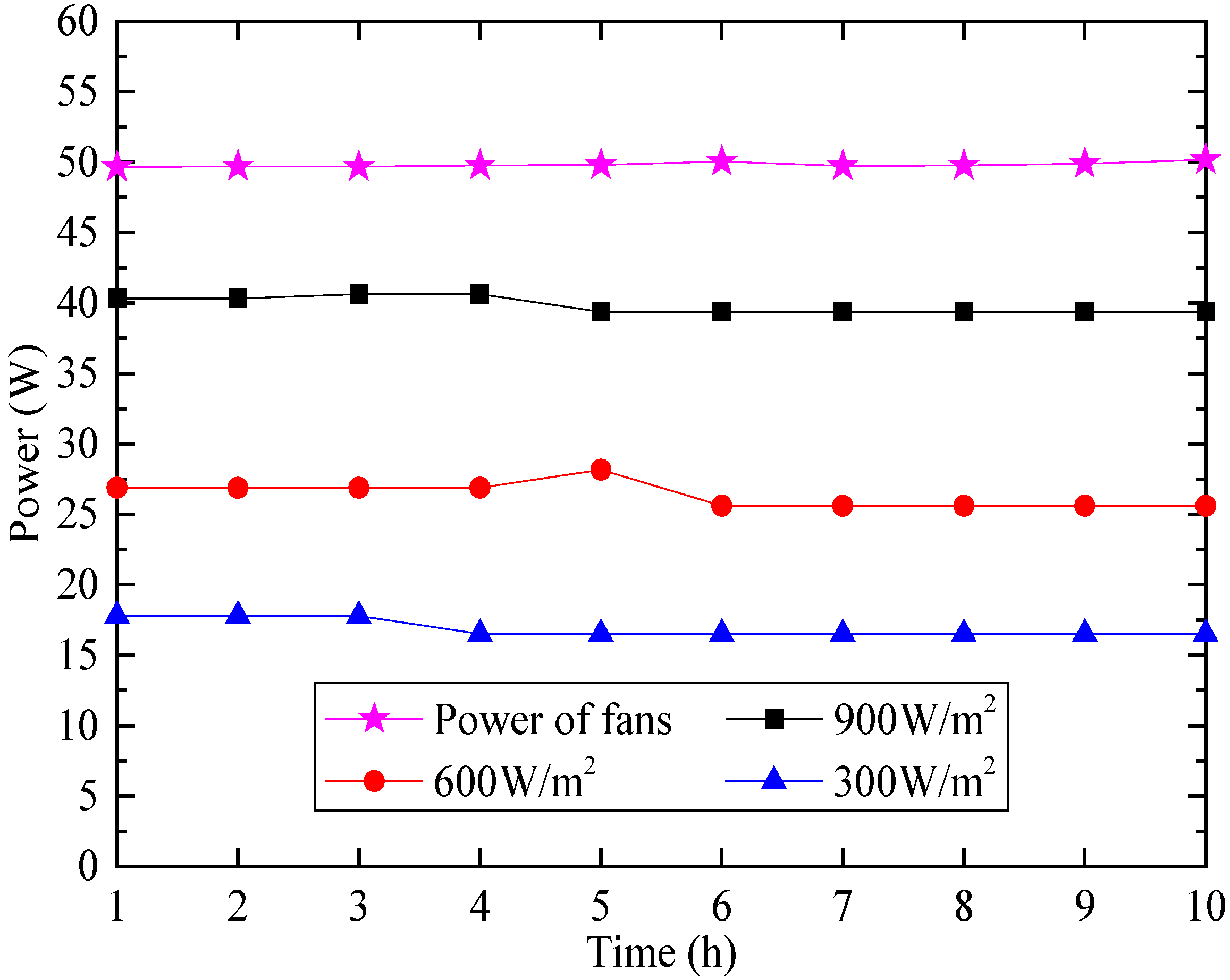
In order to investigate the operation of the fans and the PV panel, the power was tested under simulated solar radiations of 900 W/m2, 600 W/m2, and 300 W/m2, respectively, and the results are shown in Figure 11.
Figure 11 indicates that the power of the fans and the PV panel was relatively stable with time under different simulated solar radiation. The average powers of the PV panel under simulated solar radiations of 900 W/m2, 600 W/m2, and 300 W/m2 were 39.81 W, 26.37 W, and 16.89 W, respectively. This meant that the PV panel could not completely drive the fans (49.82 W) under a simulated solar radiation of 300 to 900 W/m2. Therefore, it was necessary to introduce the auxiliary power sources, e.g., battery, or to connect the PV panel to the grid to run the fans.
6. Comparison of the Testing Results with the Results from the Semi-Empirical Model
A semi-empirical model for the dehumidification process of the SPDW will be set up based on the mass balance of the desiccant module and used to compare the testing results (as in Figure 12). Four assumptions are taken into consideration in the analysis:
- (1)
- The axial gradient of the moisture content within the desiccant module is neglected.
- (2)
- Mass equilibrium between the solid desiccant and the exit air in the module is assumed.
- (3)
- Isothermal adsorption is assumed during the dehumidification process.
- (4)
- The bulk mean value of the air is assumed to simulate the mass transfer process.
For the dehumidification process, the mass balance between the dehumidified air and the solid desiccant at dτ is given as follows:
When the mass of the exit air equals that of the solid desiccant and the humidity ratio of the exit air equals that of the solid desiccant [10],
The humidity ratio of the solid desiccant db depends on the water content ratio of the solid desiccant mτ, as well as the thermo-physical properties of the solid adsorbent-adsorbate pair. For silica gel and water vapour as the adsorbent and adsorbate respectively, the linear relation of the humidity ratio of the solid desiccant db and the water content ratio of the solid desiccant mτ can be expressed as [25]:
Substituting Equations (9) and (10) into Equation (8) gives:
Solving Equation (11) with the initial condition at τ = 0, mτ = m0, gives:
Then, Equation (12) can be rewritten as:
where:
Therefore, if the initial water content ratio of the solid desiccant module (m0) and the water content ratio of the saturated solid desiccant module (me) were given, the water content ratio of the solid desiccant module in any time mτ can be predicted.
The initial water content ratio of the solid desiccant module m0 was small due to fully drying the modules in the electronic oven for 12 h at 120 °C. Therefore, m0 was neglected in this study.
The water content ratio of the saturated solid desiccant module me was determined by putting the desiccant modules into the hygrothermostat under the five experimental conditions, respectively, until the variation of the water content ratio was less than 1%; the solid desiccant was then saturated, and the results are shown in Table 6.
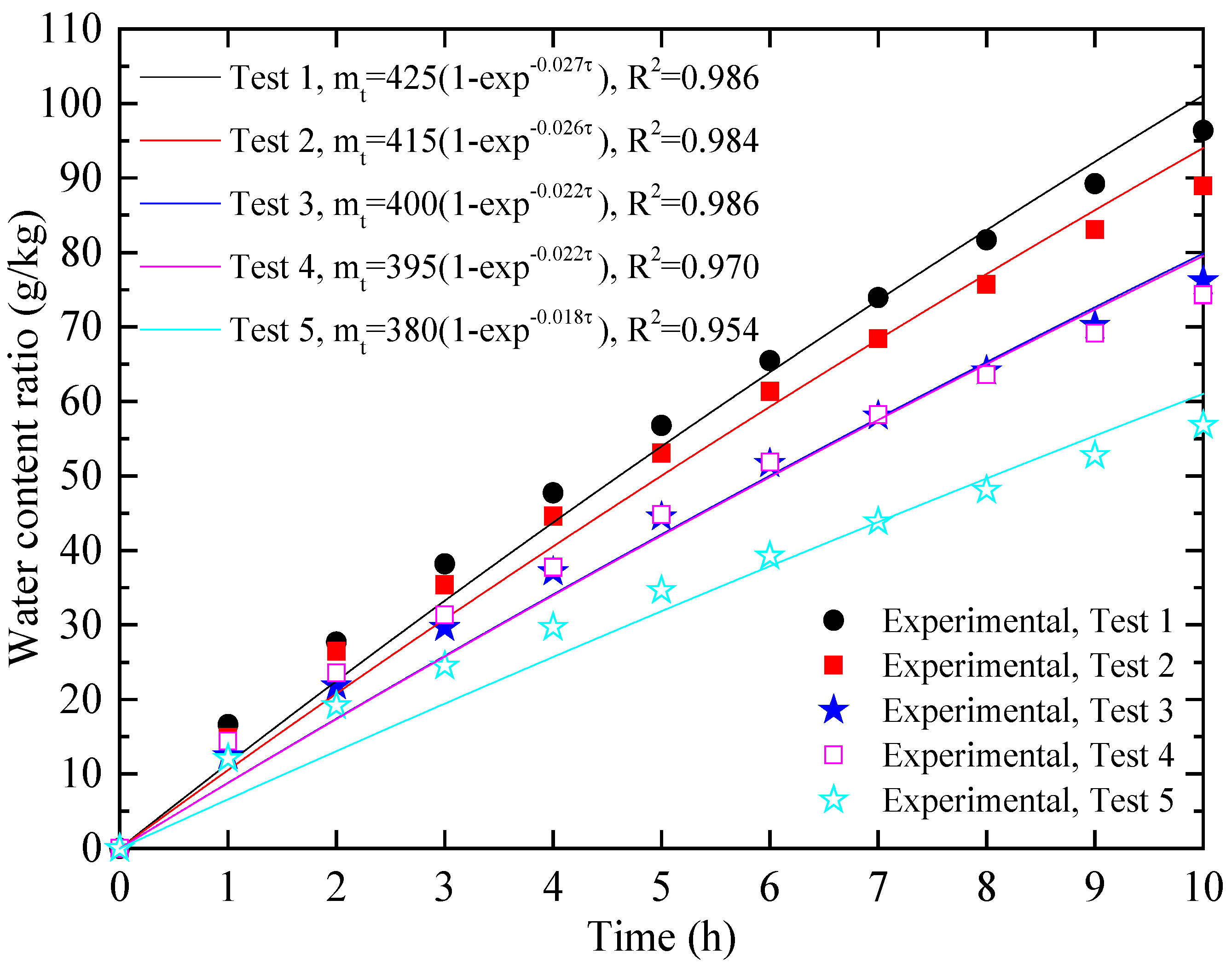
Then the water content ratio of the solid desiccant module in any time mτ could be predicted from the semi-empirical model as shown in Equation (15), and the regression constant β could be obtained from the experimental data through nonlinear regression. The results were compared with the testing results in Figure 13.
From Figure 13, by comparing the testing results with the results from the semi-empirical model, the semi-empirical model performed fairly well in predicting the water content ratio of the solid desiccant module during the experiments with mean relative errors less than 9.58%, which may be caused by the assumption of the isothermal adsorption of the model. In addition, the semi-empirical model described the relationship between the water content ratio of the solid desiccant module and the effective dehumidification time, providing an effective and convenient way to predict the water content ratio for a certain time in the dehumidification process.
7. Conclusions
In this paper, the solar-powered dehumidification window (SPDW) incorporating a double-glazed window with a solid desiccant packed bed and a photovoltaic panel was proposed. The solid desiccant bed was fit into the space between the inner and outer layers of the windows to achieve compact building integration and to save energy. In order to investigate the dehumidification and regeneration performance of the SPDW, the testing rig was constructed and tested in the laboratory under different inlet air conditions and simulated solar radiations.
For the window operated under the inlet air temperature of 19.2 °C and a relative humidity of 86.1% within the 10 h dehumidification period, the transient moisture removal reached a maximum of 7.1 g/kg and a maximum dehumidification efficiency of 58.60%. The released adsorption heat absorbed by the dehumidified air reached 89.66%, which resulted in a maximum temperature difference between the inlet and outlet air of 10.7 °C, corresponding to an inlet air temperature of 19.2 °C and a relative humidity of 86.1%, meaning that most of the released adsorption heat was transferred to the sensible heat load of the air conditioning system. The desiccant temperature increased from the beginning to the end, with a maximum of 35.3 °C for a simulated solar radiation of 900 W/m2, leading to the regeneration rate of 153 g/h. The average power of the fans was found to be 49.82 W, while the maximum power of the PV panel was 39.83 W for a simulated solar radiation of 900 W/m2, meaning that the fans could not be completely driven by the PV panel. An agreement between the results from the testing and the semi-empirical model was achieved with mean relative errors less than 9.58%, and the semi-empirical model was developed to predict the water content ratio of the desiccant modules in the dehumidification process.
Acknowledgments
This work was financially supported by the National Key Research and Development Program of China (2016YFE0133300), the Department of Science and Technology of Guangdong Province, China (2014A010106031 and 2015A010106014), the Department of Transportation of Guangdong Province, China (Science and Technology-2016-02-045), and the Department of Education of Guangdong Province, China (2016KTSCX029).
Author Contributions
Wansheng Yang and Hao Deng conceived and designed the study; Hao Deng and Song He performed the experiments and analyzed the data; Zhangyuan Wang and Xudong Zhao wrote the paper.
Conflicts of Interest
The authors declare no conflict of interest.
Nomenclature
| A | cross-sectional area, m2; |
| c | specific heat, kJ/(kg·K); |
| d | humidity ratio, g water/kg dry air; |
| Δdτ | transient moisture removal, g water/kg dry air; |
| G | mass flow rate, kg/h; |
| K1 | constant depending on the temperature range; |
| K2 | constant depending on the temperature rang |
| L | length, m; |
| M | mass, kg; |
| m | water content ratio, g water/kg dry silica; |
| Q | heat, kJ; |
| Rc | regeneration rate, g/h; |
| r | latent heat of vaporisation, kJ/kg; |
| Δt | temperature difference, °C; |
| u | velocity, m/s; |
| τ | time, h; |
| ρ | density, kg/ m3; |
| η | dehumidification efficiency, %; |
| ε | fractional void volume; |
| β | constant; |
| Subscript | |
| 0 | initial condition; |
| a | air; |
| b | equilibrium state; |
| d | dissipation; |
| e | saturated state; |
| in | inlet; |
| l | latent; |
| out | outlet; |
| s | solid desiccant; |
References
- Yang, L.; Yan, H.; Lam, J.C. Thermal comfort and building energy consumption implications—A review. Appl. Energy 2014, 115, 164–173. [Google Scholar] [CrossRef]
- Pérez-Lombard, L.; Ortiz, J.; Pout, C. A review on buildings energy consumption information. Energy Build. 2008, 40, 394–398. [Google Scholar] [CrossRef]
- Wang, R.Z.; Yu, X.; Ge, T.S.; Li, T.X. The present and future of residential refrigeration, power generation and energy storage. Appl. Therm. Eng. 2013, 53, 256–270. [Google Scholar] [CrossRef]
- Mazzei, P.; Francesco, M.; Daniele, P. HVAC dehumidification systems for thermal comfort: A critical review. Appl. Therm. Eng. 2005, 25, 677–707. [Google Scholar] [CrossRef]
- Chiang, Y.C.; Chen, C.H.; Chiang, Y.C.; Chen, S.L. Circulating inclined fluidized beds with application for desiccant dehumidification systems. Appl. Energy 2016, 175, 199–211. [Google Scholar] [CrossRef]
- La, D.; Dai, Y.J.; Li, Y.; Ge, T.S.; Wang, R.Z. Use of regenerative evaporative cooling to improve the performance of a novel one-rotor two-stage solar desiccant dehumidification unit. Appl. Therm. Eng. 2012, 42, 11–17. [Google Scholar] [CrossRef]
- Misha, S.; Mat, S.; Ruslan, M.H.; Sopian, K. Review of solid/liquid desiccant in the drying applications and its regeneration methods. Renew. Sustain. Energy Rev. 2012, 16, 4686–4707. [Google Scholar] [CrossRef]
- Hamed, A.M. Desorption characteristics of desiccant bed for solar dehumidification/humidification air conditioning systems. Renew. Energy 2003, 28, 2099–2111. [Google Scholar] [CrossRef]
- Yeboah, S.K.; Darkwa, J. A critical review of thermal enhancement of packed beds for water vapour adsorption. Renew. Sustain. Energy Rev. 2016, 58, 1500–1520. [Google Scholar] [CrossRef]
- Kabeel, A.E. Adsorption–desorption operations of multilayer desiccant packed bed for dehumidification applications. Renew. Energy 2009, 34, 255–265. [Google Scholar] [CrossRef]
- Awad, M.M.; Hamed, A.M.; Bekheit, M.M. Theoretical and experimental investigation on the radial flow desiccant dehumidification bed. Appl. Therm. Eng. 2008, 28, 75–85. [Google Scholar] [CrossRef]
- Ramzy, A.; AbdelMeguid, H.; ElAwady, W.M. A novel approach for enhancing the utilization of solid desiccants in packed bed via intercooling. Appl. Therm. Eng. 2015, 78, 82–89. [Google Scholar] [CrossRef]
- Yuan, W.X.; Zheng, Y.; Liu, X.R.; Yuan, X.G. Study of a new modified cross-cooled compact solid desiccant dehumidifier. Appl. Therm. Eng. 2008, 28, 2257–2266. [Google Scholar]
- Ge, T.S.; Dai, Y.J.; Wang, R.Z.; Peng, Z.Z. Experimental comparison and analysis on silica gel and polymer coated fin-tube heat exchangers. Energy 2010, 35, 2893–2900. [Google Scholar] [CrossRef]
- Ge, T.S.; Dai, Y.J.; Wang, R.Z.; Li, Y. Feasible study of a self-cooled solid desiccant cooling system based on desiccant coated heat exchanger. Appl. Therm. Eng. 2013, 58, 281–290. [Google Scholar] [CrossRef]
- Peng, Z.Z.; Dai, Y.J.; La, D.; Wang, R.Z. Transient dehumidification performance of a novel regenerative desiccant heat exchanger. Acta Energiae Sol. Sin. 2011, 32, 530–536. [Google Scholar]
- Wang, H.H.; Ge, T.S.; Zhang, X.L.; Zhao, Y. Experimental investigation on solar powered self-cooled cooling system based on solid desiccant coated heat exchanger. Energy 2016, 96, 176–186. [Google Scholar] [CrossRef]
- Zhao, Y.; Dai, Y.J.; Ge, T.S.; Wang, H.H.; Wang, R.Z. A high performance desiccant dehumidification unit using solid desiccant coated heat exchanger with heat recovery. Energy Build. 2016, 116, 583–592. [Google Scholar] [CrossRef]
- Zhang, L.Z.; Niu, J.L. Performance comparisons of desiccant wheels for air dehumidification and enthalpy recovery. Appl. Therm. Eng. 2002, 22, 1347–1367. [Google Scholar] [CrossRef]
- Hamed, A.M.; Abd-Elrahman, W.R.; El-Emam, S.H.; Awad, M.M. Theoretical and experimental investigation on the transient coupled heat and mass transfer in a radial flow desiccant packed bed. Energy Convers. Manag. 2013, 65, 262–271. [Google Scholar] [CrossRef]
- Ramzy, A.K.; Kadoli, R.; TP, A.B. Experimental and theoretical investigations on the cyclic operation of TSA cycle for air dehumidification using packed beds of silica gel particles. Energy 2013, 56, 8–24. [Google Scholar] [CrossRef]
- Techajunta, S.; Chirarattananon, S.; Exell, R.H.B. Experiments in a solar simulator on solid desiccant regeneration and air dehumidification for air conditioning in a tropical humid climate. Renew. Energy 1999, 17, 549–568. [Google Scholar] [CrossRef]
- Kumar, A.; Chaudhary, A.; Yadav, A. The regeneration of various solid desiccants by using a parabolic dish collector and adsorption rate: An experimental investigation. Int. J. Green Energy. 2014, 11, 936–953. [Google Scholar] [CrossRef]
- Yadav, A.; Bajpai, V.K. Experimental comparison of various solid desiccants for regeneration by evacuated solar air collector and air dehumidification. Dry. Technol. 2012, 30, 516–525. [Google Scholar] [CrossRef]
- Hamed, A.M.; El Rahman, W.R.A.; El-Emam, S.H. Experimental study of the transient adsorption/desorption characteristics of silica gel particles in fluidized bed. Energy 2010, 35, 2468–2483. [Google Scholar] [CrossRef]
Figure 1.
Schematic of the solar-powered dehumidification window (SPDW): (a) dehumidification mode; and (b) regeneration mode 1-Photovoltaic panel; 2-Fans; 3-Desiccant modules; 4-Flat-plate glass; 5-Orifice plates; 6-Air inlet.
Figure 1.
Schematic of the solar-powered dehumidification window (SPDW): (a) dehumidification mode; and (b) regeneration mode 1-Photovoltaic panel; 2-Fans; 3-Desiccant modules; 4-Flat-plate glass; 5-Orifice plates; 6-Air inlet.
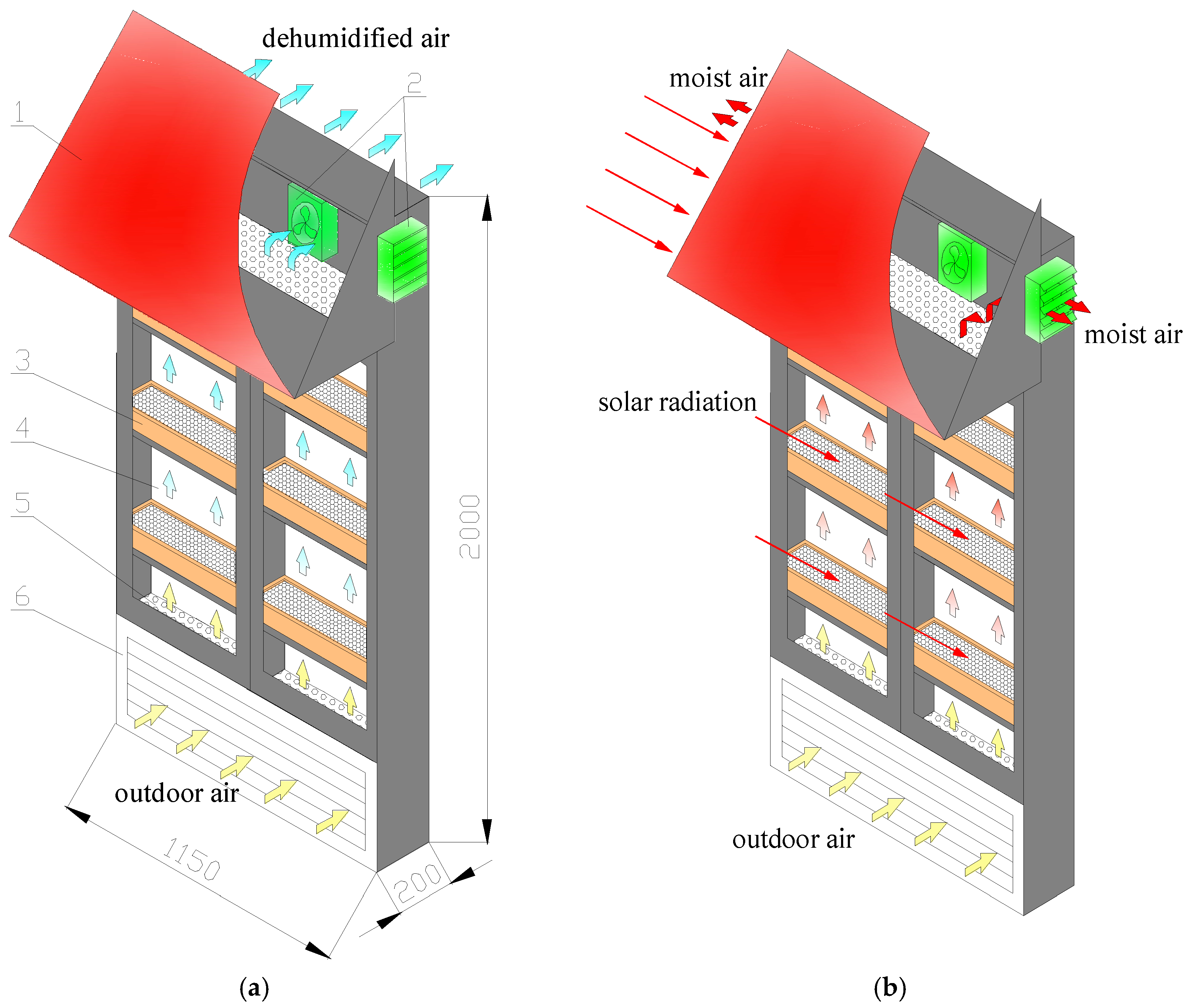
Figure 2.
Testing rig of the proposed SPDW: (a) dehumidification mode; and (b) regeneration mode 1-Air inlet; 2-Electric heater; 3-Ultrasonic humidifier; 4-Mixing chamber; 5-Double shutter; 6-Temperature/humidity sensor; 7-Solid desiccant module (Silica gel); 8-Thermocouple; 9-Inner layer of the flat-plate glass; 10-Outer layer of the flat-plate glass; 11-Fans; 12-PV panel; 13-Testing space; 14-Air outlet; 15-Bracket; 16-Xenon lamps.

Figure 3.
Image of the testing rig.

Figure 4.
Image of the desiccant modules embedded in the window.

Figure 5.
Image of the xenon lamps.

Figure 6.
Variation of the transient moisture removal of the solid desiccant modules with time.
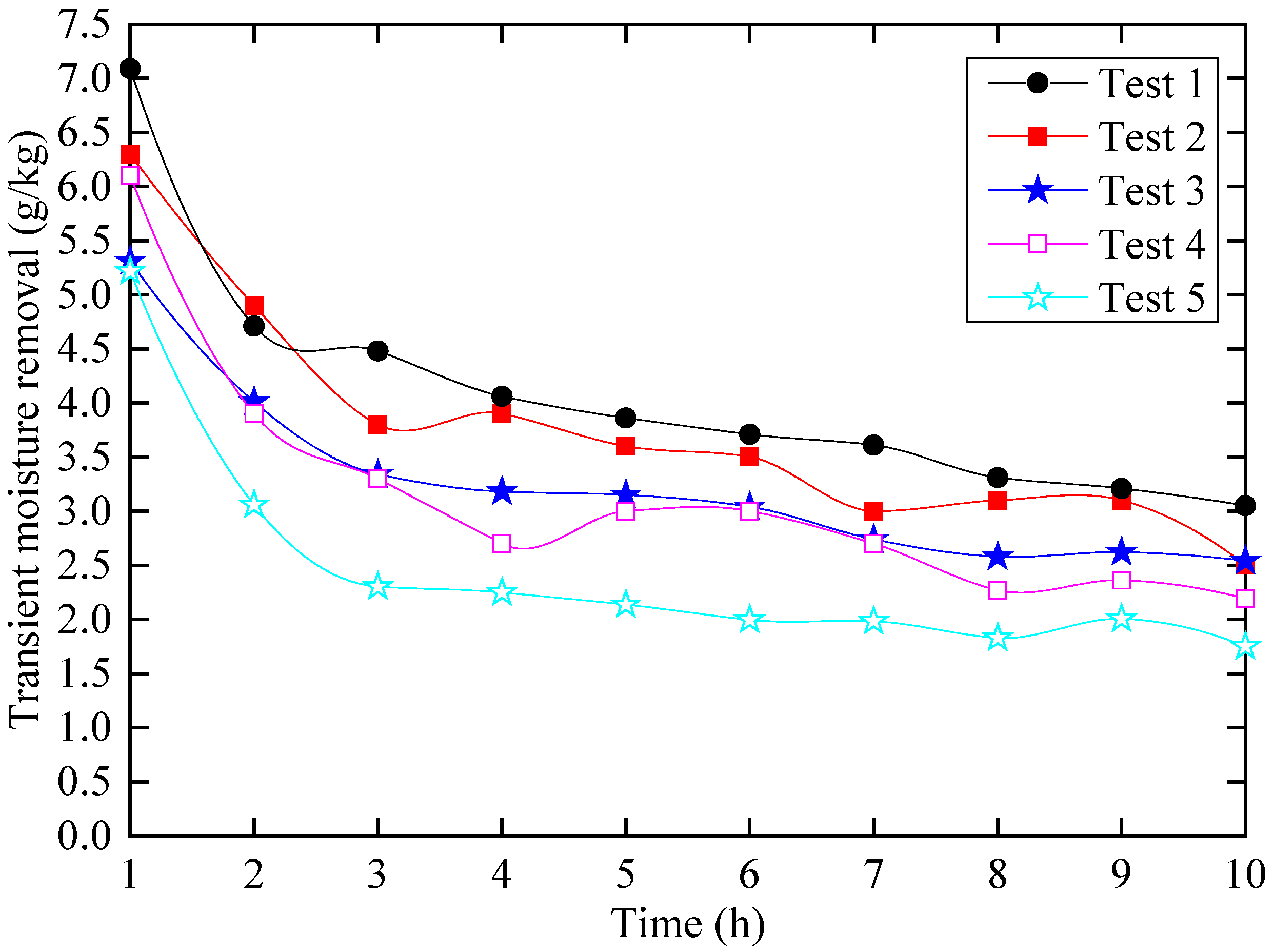
Figure 7.
Variation of the dehumidification efficiency of the solid desiccant modules with time.

Figure 8.
Variation of the temperature difference between the inlet and outlet air with time.

Figure 9.
The variation of the temperature of the solid desiccant modules with time.

Figure 10.
The variation of the regeneration rate of the solid desiccant modules with time.

Figure 11.
The variation of the power of the fans and photovoltaic (PV) panel with time.

Figure 12.
The mass transfer process for the proposed solid desiccant module.
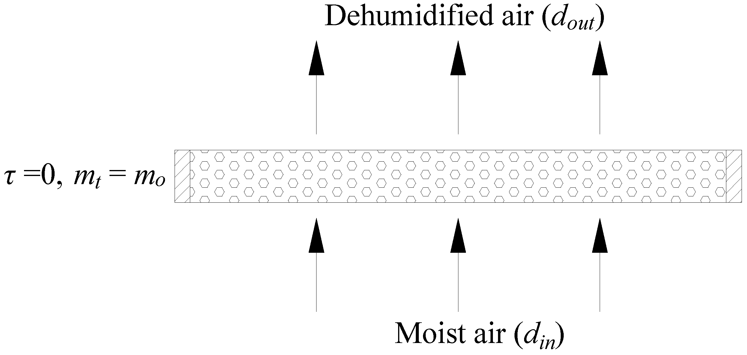
Figure 13.
Comparison of the results from the testing and semi-empirical model.

Table 1.
The parameters of the main components of the solar-powered dehumidification window (SPDW).
| Name | Type | Manufacturer | Main Parameters |
|---|---|---|---|
| Material | |||
| Macro-porous silica gel | - | Tasike Material Company (Dongguan, China) | Average diameter: 2 to 4 mm; pore volume: 0.34 to 0.40 L/kg; particle density: >600 kg/m3; specific heat: 0.92 kJ/(kg·K) |
| Devices | |||
| Electric heater | DJR | WeiRe Electronic and Technology Company (Suzhou, China) | Power range: 250 to 500 W |
| Ultrasonic humidifier | H-010 | Shide Electric Company (Guangzhou, China) | Humidification capacity: 0 to 800 mL/h; power: 60 W |
| Multi-channel temperature and humidity monitor | PC-2WS | Solar Science & Technology Company (Jinzhou, China) | Accuracy: ±2% in humidity, ±0.2 °C in temperature |
| 64-channel temperature logger | JK-XU | Jinailian Electronic Technology Company (Changzhou, China) | Sensor: K-type; accuracy: ±(value × 0.5% + 1) °C |
| Fan | ASB20-4-1M | Changzhou Jinling Electric Company (Changzhou, China) | Mass flow rate: 486 m3/h; power: 28 W |
| Anemometer | 405-V1 | Testo Company (Beijing, China) | Range: 0 to 10 m/s; accuracy: 0.01 m/s |
| Xenon lamp | AHD2000W | Anhongda Opto Technology Co. Ltd. (Shenzhen, China) | Power: 2000 W |
| Pyranometer | JTTF | JT Technology Company (Jinzhou, China) | Spectrum range: 0.3 to 3.2 μm; sensitivity: 7 to 14 mV/(kW·m2); Response time: <35 s |
| Electric power instrument | BDYB | Northmeter Co. Ltd. (Shenzhen, China) | Accuracy grade: 1.0 |
| PV panel | PV-HY-8526 | Fujie Solar Company (Guangzhou, China) | Output power: 100 W; transfer efficiency: 18% |
| Electronic balance | TCS-01 | Bailunsi Electronic and Technology Company (Xiamen, China) | Measurement accuracy: 2 g |
| Electronic oven | HN101-2A | Hunan Scientific Instrument Company (Nantong, China) | Temperature range: 10 to 300 °C; accuracy: ±1.0 °C |
| Hygrothermostat | BYCT-TH150B | Boya Equipment Company (Dongguan, China) | Temperature range: −40 to 150 °C; relative humidity range: 20 to 90%; temperature accuracy: ±0.5 °C |
Table 2.
Inlet air conditions for the experiments.
| Test No. | Temperature (°C) | Relative Humidity (%) | Humidity Capacity (g/kg) | Mass Flow Rate (kg/h) |
|---|---|---|---|---|
| 1 | 19.2 | 86.1 | 12.1 | 45.7 |
| 2 | 19.6 | 79.2 | 11.4 | 41.4 |
| 3 | 19.4 | 74.2 | 10.5 | 43.2 |
| 4 | 24.4 | 79.5 | 15.4 | 42.5 |
| 5 | 24.2 | 75.5 | 14.2 | 43.7 |
Table 3.
The temperature difference of the inlet and outlet air for five tests (°C).
| Time (h) | Test 1 | Test 2 | Test 3 | Test 4 | Test 5 |
|---|---|---|---|---|---|
| 1 | 5.0 | 4.4 | 2.9 | 2.5 | 2.2 |
| 2 | 9.0 | 8.4 | 6.2 | 5.3 | 4.2 |
| 3 | 10.7 | 10.1 | 8.4 | 7.4 | 6.6 |
| 4 | 10.2 | 8.6 | 8.8 | 7.7 | 6.4 |
| 5 | 10.0 | 8.9 | 8.6 | 7.5 | 6.3 |
| 6 | 9.7 | 8.0 | 8.1 | 6.4 | 5.3 |
| 7 | 8.2 | 6.5 | 5.9 | 5.7 | 4.5 |
| 8 | 7.7 | 6.0 | 6.6 | 5.4 | 4.4 |
| 9 | 7.3 | 5.9 | 5.8 | 4.8 | 3.6 |
| 10 | 6.5 | 5.3 | 3.8 | 4.3 | 3.4 |
| Mean | 8.4 | 7.2 | 6.5 | 5.7 | 4.7 |
Table 4.
The temperature rise of the solid desiccant modules for five tests (°C).
| Time (h) | Test 1 | Test 2 | Test 3 | Test 4 | Test 5 |
|---|---|---|---|---|---|
| 1 | 18.3 | 15.7 | 13.1 | 22.1 | 18.6 |
| 2 | 20.1 | 17.1 | 14.5 | 21.4 | 19.4 |
| 3 | 17.8 | 16.1 | 12.9 | 17.6 | 17.1 |
| 4 | 16.1 | 14.8 | 11.6 | 15.3 | 14.7 |
| 5 | 15.0 | 12.7 | 10.5 | 14.8 | 12.6 |
| 6 | 14.1 | 11.4 | 9.4 | 13.5 | 11.3 |
| 7 | 12.1 | 10.8 | 8.7 | 12.3 | 10.1 |
| 8 | 10.3 | 9.6 | 7.4 | 11.4 | 8.7 |
| 9 | 9.9 | 9.2 | 6.8 | 10.5 | 7.9 |
| 10 | 8.8 | 8.0 | 5.2 | 9.5 | 8.1 |
| Mean | 14.2 | 12.5 | 10.0 | 14.8 | 12.9 |
Table 5.
The calculation of the four heat transfer parameters of the SPDW during the dehumidification process.
Table 5.
The calculation of the four heat transfer parameters of the SPDW during the dehumidification process.
| Test | Ql (kJ) | Qa | Qs | Qd | |||
|---|---|---|---|---|---|---|---|
| Amount (kJ) | Percentage (%) | Amount (kJ) | Percentage (%) | Amount (kJ) | Percentage (%) | ||
| 1 | 4004.60 | 3590.33 | 89.66 | 241.18 | 6.02 | 173.08 | 4.32 |
| 2 | 3674.21 | 3128.75 | 85.15 | 211.88 | 5.77 | 333.58 | 9.08 |
| 3 | 3168.40 | 2826.11 | 89.20 | 168.54 | 5.32 | 173.75 | 5.48 |
| 4 | 3072.10 | 2479.92 | 80.72 | 274.39 | 8.94 | 317.78 | 10.34 |
| 5 | 2389.21 | 2040.11 | 85.39 | 227.06 | 9.50 | 122.03 | 5.11 |
| Mean | 3261.70 | 2832.64 | 86.55 | 224.68 | 7.11 | 204.39 | 6.34 |
Table 6.
The testing results of the water content ratio of the saturated solid desiccant module.
| Test No. | 1 | 2 | 3 | 4 | 5 |
|---|---|---|---|---|---|
| Water content ratio (g/kg) | 425 | 415 | 400 | 395 | 380 |
© 2017 by the authors. Licensee MDPI, Basel, Switzerland. This article is an open access article distributed under the terms and conditions of the Creative Commons Attribution (CC BY) license (http://creativecommons.org/licenses/by/4.0/).
Share and Cite
MDPI and ACS Style
Yang, W.; Deng, H.; Wang, Z.; Zhao, X.; He, S. Performance Investigation of the Novel Solar-Powered Dehumidification Window for Residential Buildings. Energies 2017, 10, 1369. https://doi.org/10.3390/en10091369
AMA Style
Yang W, Deng H, Wang Z, Zhao X, He S. Performance Investigation of the Novel Solar-Powered Dehumidification Window for Residential Buildings. Energies. 2017; 10(9):1369. https://doi.org/10.3390/en10091369
Chicago/Turabian StyleYang, Wansheng, Hao Deng, Zhangyuan Wang, Xudong Zhao, and Song He. 2017. "Performance Investigation of the Novel Solar-Powered Dehumidification Window for Residential Buildings" Energies 10, no. 9: 1369. https://doi.org/10.3390/en10091369
Note that from the first issue of 2016, this journal uses article numbers instead of page numbers. See further details here.