A Design Method for Making an LCC Compensation Two-Coil Wireless Power Transfer System More Energy Efficient Than an SS Counterpart


1
School of Electrical and Power Engineering, China University of Mining and Technology, Xuzhou 221008, China
2
Electrical Energy Management Research Group, University of Bristol, Bristol BS8 1TH, UK
*
Author to whom correspondence should be addressed.
Energies 2017, 10(9), 1346; https://doi.org/10.3390/en10091346
Submission received: 18 July 2017
/
Revised: 19 August 2017
/
Accepted: 1 September 2017
/
Published: 6 September 2017
(This article belongs to the Special Issue Emerging Power Electronics Technologies for Power Systems and Machine Drives)
Abstract
:A new design approach is presented in this paper to show that under certain conditions, in a two-coil wireless power transfer system, the double-sided inductor-capacitor-capacitor (LCC) compensated wireless power transfer (LCC-WPT) system can be more energy efficient than the series-series (SS) compensated wireless power transfer (SS-WPT) system for the same load power, with special attention being paid to the effect that the parasitic coil and capacitor resistances have on the system efficiency. To make a fair comparison between the SS and LCC WPT systems, the direct current (DC) link voltage was adjusted to set equal load power for the two systems whilst using identical transmit and receive coils, coil-to-coil distance and load resistance. The system performance in terms of the system efficiency, the voltage stresses on the components, and the losses in the power devices were analysed for a practical system, comparing the LCC-WPT system and the SS-WPT system with respect to the load resistance. The effect of coil misalignment on the transferred power and efficiency for the two systems was compared. The theoretical proof and the conditions for meeting the objective are derived and practically verified in a two-coil WPT practical prototype, showing good agreement between analysis and experiments.
1. Introduction
Wireless power transfer (WPT) systems have been studied for a century since the great contribution made by Nikola Tesla in the early 1900s [1]. Due to the elimination of physical contacts between the source and the load and the energy can be transferred from a power source to isolated loads across a large air gap, through an alternating magnetic field, the WPT system can greatly enhance the flexibility and safety of electrical equipment. Therefore, this technology has been a very active research topic and has been widely used in implantable devices [2,3,4,5], electric vehicles [6,7,8,9], and portable devices [10,11] to power up a device or temporarily recharge its batteries.
Because the energy is wirelessly transferred through mutual inductance between the transmit and receive coils, the leakage inductance does not have a direct contribution to the active power transfer. Also, because of the large gap between the transmit and receive coils, the coupling coefficient between the two coils is small, typically in the range of 5–30%, depending on the distance, alignment, and size of the coils. This feature leads to a WPT system with a large leakage inductance but a small mutual inductance. To counteract the effect of low coupling factor, transmit and receive coils are tuned by compensation capacitors to resonate at the operating frequency. Different compensation topologies have been proposed and implemented in a wide range of applications to tune the two coils to operate at resonance. There are four basic topologies of compensation circuit depending on how the compensation capacitors are added to the transmit and receive coils: series-series (SS), series-parallel (SP), parallel-series (PS), and parallel-parallel (PP) topologies, and these have been analysed in detail in [12,13]. Combinations of basic series and parallel topologies are proposed to achieve different purposes; for example in [14], a dual topology is realised by switching between a parallel-compensated secondary side and a series-compensated secondary side to realise both constant current mode and constant voltage mode. High order topologies, such as LLC-S [15], CLC-LC [16], LCC-LCC [17,18] (the compensation topology A-B means that the primary-side is compensated by A and the secondary-side is compensated by B; here, L stands for a inductor, C stands for a capacitor and S stands for a series connected capacitor), are also proposed to achieve higher efficiency or for other purposes. When the LCC compensation network is adopted at the secondary side, the reactive power at the secondary side could be compensated to form a unit power factor pickup [19]. By utilizing an LCC compensation network, a zero current switching (ZCS) condition could be achieved by tuning the compensation network parameters [18]. In [17], the author proposes a double-sided LCC compensation network and a tuning method to realize zero voltage switching (ZVS) for the primary-side switches, and it is shown that the LCC-compensated WPT system has a good performance in terms of the robustness against possible coil misalignment. However, the author did not analyse the impacts caused by the additional compensation inductor, and a comparison between basically compensated WPT systems and the LCC-WPT system was necessary to find the advantages and disadvantages of the LCC-WPT system. In [20], the authors analyse the difference between the SS and LCC WPT systems with tuned/mistuned coils in these two topologies, but the comparison is only in regard to efficiencies without considering the variation of the output power and the mistuning is caused by the variations of the relative position between primary and secondary sides; however, if there is no ferrite used in the system, the inductance of the coil will not change with the misalignment of the two coils, and the mistuning phenomenon will not occur. Another paper also compared the SS compensation topology to the LCC compensation topology [21], it is shown that under certain conditions, the LCC-WPT system could effectively reduce the magnetic field but with less system efficiency compared to the SS-WPT system. Identical transmit and receive coils are used for a fair comparison between the SS and LCC compensation topologies in these two papers, therefore, in our work, the SS-WPT system and the LCC-WPT system will also use the same transmit and receive coils to compare these two WPT systems. Almost all of these papers use superposition theory instead of coupled circuit model to calculate and analyse the WPT system performance in the LCC-WPT system, which is more complex and requires knowledge of the input and output voltages. Many papers simplify the analysis by neglecting parasitic resistances, i.e., coil resistance and capacitor equivalent series resistances (ESR), which must be included to accurately predict system performance. As there may be advantages of the LCC-WPT system, which has attracted much attention, it is selected for study in this paper.
In this paper, we determine the conditions under which an LCC system can be more efficient than an SS system when providing the same load power to the same load with same transmit and receive coils, notwithstanding additional losses in the added inductor and capacitor on each side. The proposed SS-WPT system and LCC-WPT system in this paper both had a symmetrical structure, allowing their use in a bidirectional WPT system. To better analyse the performance of WPT system, the coupled circuit method was applied. In order to obtain a clear understanding of the advantages and disadvantages of these two compensation topologies, a comparison between the SS-WPT system and double-sided LCC-WPT system was conducted to investigate the WPT system performance under the conditions of (a) same output power with different load resistance (b) coil-to-coil horizontal misalignment. The voltage stress on the components in the WPT system was also studied for practical purposes. Even though this paper only focused on the comparison between the SS-WPT system and the LCC-WPT system, the analysis concept was suitable for any comparison among different compensation topologies.
2. Theoretical Analysis
2.1. SS-WPT System Circuit Model
The schematic diagram of the experimental SS-WPT system is shown as Figure 1a. The primary side coil-system consists of the transmit coil L1 and its series connected compensation capacitor C1. A voltage source high frequency inverter drives the primary side coil-system with a square-wave voltage. Usually, C1 is made resonant with L1 to reduce the voltage-ampere (VA) required to provide the required primary current. When the driving frequency equals the resonant frequency, the primary side circuit is purely resistive, but has a high inductive reactance to harmonics; as a result, the current flowing through the L1C1 resonant circuit is sinusoidal. This current generates a magnetic field around L1, which induces a voltage in L2 by the mutual inductance between the two coils. The compensation capacitor on the secondary side C2, which is also series connected and resonant with the receive coil L2, cancels out the inductive reactance of the secondary coil, which would otherwise seriously limit the load current. A bridge rectifier followed by a reservoir capacitor provides direct current to the load. In this way, electric energy is transferred through the air from the transmit coil to the receive coil [22].
A simplified equivalent circuit can be derived for the system as shown in Figure 1b, where Vs is the equivalent voltage source with an internal resistance RS, U1 is the output voltage phasor of the inverter applied on the primary coil-system; U2 is the output voltage phasor of the secondary coil-system and the input voltage to the bridge rectifier. The bridge rectifier, filter capacitor and the actual load are treated as an equivalent resistance RL. In this simplified model, R1 and R2 are the parasitic resistance in the primary and secondary sides respectively, including the resistance in the coils and the compensation capacitors. I1 and I2 are the current phasors for the primary and the secondary sides respectively. The secondary-side series resonant circuit forces a sinusoidal current through the rectifier, resulting in a square-wave voltage at the rectifier input, since Cf at the rectifier output, the voltage across the load is nearly constant, with a small ripple component. Because power transfer is the product of the root mean square (RMS) value of the sinusoidal current and the RMS value of the fundamental of the square voltage waveform, of its peak value, then the relationship between the actual and the equivalent loads can be expressed as Equation (1).
With the lumped-element circuit shown in Figure 1b, the SS-WPT system can be expressed in the matrix form according to Kirchhoff’s voltage law (KVL) as follows:
where ) is the impedance of the primary side; is the impedance of the secondary side; is the equivalent resistance of the inverter and DC power supply, and ωd is the driving angular frequency.
Therefore, the current vector in the primary and secondary sides can be derived as Equations (3) and (4).
For a resonant WPT system, the relationship between the self-inductance of the coil and the capacitance of the compensation capacitors are related to the resonance angular frequency and can be found as Equation (5), where ωr is the resonance angular frequency.
Also, when the WPT system operates in a resonant condition, the driving frequency equals to the resonance frequency, as in Equation (6).
The primary-side and secondary-side impedance can then be expressed as Equations (7) and (8).
As analysed previously, the coil currents in both primary-side and secondary-side are sinusoidal, therefore, the fundamental harmonics approximation (FHA) can be used to analyse the working principle. The power transferred from the primary side and the power received by the secondary side can then be calculated by the product of the amplitudes of the voltage and current when the system operates at the resonant condition as Equations (9) and (10). Accordingly, the SS-WPT system efficiency is as shown in Equation (11).
2.2. LCC-WPT Circuit Model
The double sided LCC-WPT system (shown in Figure 2a) has been extensively studied in recent years. As with the SS-WPT system, the primary side LCC compensation circuit and the transmit coil constitute the primary coil-system and are driven by an H-Bridge inverter. Power is transmitted to the secondary coil system, which consists of the receive coil and the additional secondary side LCC compensation circuit, and supplies the load via a bridge rectifier and a filter capacitor.
As shown in Figure 2, compared with the SS-WPT system, additional series inductors Lf1 & Lf2 and additional parallel capacitors Cf1 & Cf2 are added to both the primary and secondary sides. For the primary side, Lf1 is series connected after the inverter, and Cf1 is paralleled connected before the original compensation capacitor C1. At the secondary side, the additional compensation inductor Lf2 and capacitor Cf2 are connected between the original compensation capacitor C2 and the H-bridge inverter. A simplified circuit only containing the LCC compensation topology and the coil system can be derived with all components’ stray resistances combined together as shown in Figure 2b, to simplify the calculation of the wireless power transfer characteristics. In the following analysis, U1, U2, I1, I2, ILf1, and ILf2 are adopted to represent the phasor form of the corresponding variables.
The LCC-WPT system also can be expressed in the matrix form according to KVL with the combined circuit elements shown in Figure 2b as Equation (12):
where
For a high-order system as in Figure 2a, there are multiple resonant frequencies [17], as can be seen from the system frequency-response plot in Figure 3, where the additional inductors are twice the mutual inductance, and the load resistance is 100 Ω. The detailed design of the 85 kHz resonant LCC-WPT system parameters will be given in the next part.
Here, only one resonance frequency, corresponding to ωr in Equation (20) is considered, instead of the overall frequency-domain characteristics, which are only relevant to inductances/capacitances in the system, independent of coupling coefficient and load conditions such as the SS-WPT system [17].
Therefore, the vector current flowing through the primary and secondary sides can be easily derived from the matrix form as in the following Equations (19)–(22). ILf1 is the inverter output current, I1 is the current flowing in the transmit coil, I2 is the current flowing in the receive coil, and ILf2 is the current flowing into the rectifier.
When the LCC-WPT system is tuned to have a constant resonant frequency, which means the input voltage VS and current ILf1 of the compensated primary coil-system are in phase and its amplitude is related to the relative coil-to-coil distance and load condition; the output current ILf2 is determined by the input voltage VS for a given system design and fixed load resistance; the output voltage U2 is also in phase with the output current ILf2. Therefore, the product of the fundamental harmonic of the output voltage and current of the inverter, input voltage and current of the rectifier can be used to calculate the power in the both sides and the accordingly system efficiency as follows:
3. Effects of the Added Inductor in the LCC-WPT System
In this section, the effect on load power and efficiency due to the additional LCC compensation components is analysed. Lf is allowed to vary from 0.1 M12 to 2 M12 in 0.2 M12 steps. The performance of the LCC-WPT system is compared with an SS-WPT system under the condition of the same input DC voltage. The self-inductance of the transmit and receive coils is 66 μH, the coupling coefficient is 0.27, and the DC input voltage is 100 V.
3.1. Efficiency Oriented Design of the LCC-WPT System
As the SS-WPT system is treated as the benchmark in this study, the following analysis aims at determining the conditions for higher efficiency in the LCC-WPT system, then the SS-WPT system with given specified transmit and receive coils; therefore the following inequality should be met in Equation (28).
From Equations (13)–(24), it can be found that the vector currents flowing in the primary and secondary sides of the LCC-WPT system are very complex to express, making the inequality (28) very difficult to solve.
If the stray resistance on the coils and capacitors is neglected for simplicity, then for the SS-WPT system, by substituting the current expressions into the power expression and the efficiency expression, the primary side power, the secondary side power and the system efficiency can be expressed as (29)–(31) at the resonant condition. It can be found that the system efficiency is only related to the resonance frequency, load resistance, mutual inductance and equivalent resistance of the driver.
Following the same approach applied in the analysis of SS-WPT system, the resistance on all the inductors and capacitors in the LCC-WPT system are also neglected for simplicity, and since the LCC-WPT system has a symmetrical structure, expressions (32)–(35) are valid.
Now, the power transferred from the primary side, the power received by the secondary side and the system efficiency of the LCC-WPT system can be expressed as Equations (36)–(38).
Comparing Equation (31) and Equation (38), it can be noticed that an extra variable Lf is introduced in the LCC-WPT system which affects the efficiency of the system.
Substitute Equations (31) and (38) into Equation (28), the inequality is gained as in Equation (39).
After some simple mathematical manipulations, inequality Equation (39) can be simplified as Equation (40).
Equations (1)–(39) now provide the mathematical proof, and inequality (40) specifies the required conditions for the system efficiency of an LCC-WPT system to be higher than that of an SS-WPT system. It means that as long as Lf > M12, the LCC-WPT system has higher energy efficiency than the SS-WPT system for the same extended transfer distance and same load resistance with same transmit and receive coils. However, this analysis has neglected coil and capacitor ESR, and therefore is only approximately true when the parasitic resistance on all the components are small enough and can be neglected, and if the parasitic resistance cannot be ignored, the inequality (40) does not hold any longer, as is shown by simulation and experiment for a practical system.
The calculated variation of the system efficiency and output power of the LCC-WPT system according to Equations (29)–(38) are plotted in Figure 4 against the variation of the compensation inductance Lf, where the SS-WPT system and the LCC-WPT system have the same DC input voltage and load resistance. The parasitic resistances are neglected as in the previous analysis.
In Figure 4, the red lines are the system efficiency, and blue lines are the system output power, the solid lines stand for the LCC-WPT system, and the dotted lines stand for the SS-WPT system. It can be seen from Figure 4 that with Lf increasing, the LCC-WPT system efficiency shows a rising trend, and when Lf exceeds M12, the efficiency of LCC-WPT system will exceed the system efficiency of the equivalent SS-WPT system as expected; with Lf further increasing, the efficiency curve of LCC-WPT will continue to increase but will be limited by RS. Focusing on the system output power in Figure 4, there is a peak value for the LCC-WPT system when Lf ≈ 0.6 M12, which is much higher compared to the output power of the SS-WPT system. And it can also be seen that there are two values of Lf which can make the LCC-WPT system output the same power as the SS-WPT system, one of these two is when Lf = M12.
3.2. Output Power Regulation of the LCC-WPT System
Another perspective to compare the two compensation topologies is to look at their performance (efficiency and component stresses) when they have the same power transfer capacity with identical load condition and coil-to-coil distance. Therefore, this part aims at designing these two WPT systems for the same output power.
From Figure 4, it is seen that the output power curves of the LCC system cross over with the output power of the SS-WPT system at two values of Lf; therefore, one way to tune the output power is to tune Lf with same DC input voltage and load resistance. Based on Equations (30) and (37), in order to design an LCC-WPT system with equal output power as an SS-WPT system as expressed in Equation (41), the inductance of Lf can be tuned to achieve this goal without changing any other parameters of the LCC-WPT system.
By substituting Equations (30) and (37) into Equation (41), a simple inequality, Equation (42), can be derived.
However, according to the previous analysis, Lf > M12 is needed in order to achieve higher efficiency for the LCC-WPT system. Therefore, another approach to regulate the output power is to tune the DC-link voltage according to (37). The DC voltage in the LCC-WPT system can be tuned to meet the output power requirement with arbitrary Lf. In this case, the required DC input voltage can be obtained from Equations (30) and (37) as in Equation (43) when the inverter is assumed to have the same voltage ratios, i.e., the relationship between VDC and the fundamental RMS voltage of the square wave driving voltage for the two WPT systems. In the latter analysis, VDC_SS and VDC_LCC are shortened as VSS and VLCC respectively.
Based on Equation (43), the variations of required VLCC are plotted in Figure 5 with respect to various Lf and RL. In this calculation, the equivalent voltage source internal resistance is set to be 0.5 Ω, but this value will vary according to the practical system operating condition.
It can be seen from Figure 5 that, when Lf = M12, the system input DC voltage does not need to be adjusted to get the same output power as the SS-WPT system. When Lf is smaller than M12 (Lf = 0.5 M12), the required DC input voltage of the LCC-WPT system is smaller than that of the SS-WPT system, but the system efficiency will be lower, with a smaller Lf from Figure 4, the required input power and current will be higher in order to hold the output power constant, which will not only decrease the system efficiency, but also stress the switching devices in the inverter. When Lf is greater than the M12 (e.g., Lf = 1.5 M12, Lf = 2 M12), even though the system efficiency can be improved, the input DC voltage of the LCC-WPT system will be much higher than the SS-WPT system, which will increase voltage stress on the components used in the LCC-WPT system. The extra voltage can lead to higher failure rate of the components. The higher Lf is, the higher the DC input voltage required.
Therefore, while utilizing the VDC tuning approach to adjust the output power, the stress on the system components should be considered, and this will be studied in the next section. It should be noticed that DC input voltage tuning approach can only provide approximate values, and requires manual tuning in a practical system to obtain the desired output power, as the calculations are based on ideal components, and RS will vary according to the system operating condition.
3.3. Analysis of the Impacts Caused by Lf
A generalised expression presented in this paper, which includes parasitic resistances in the coil-system, was found to be long and unwieldy; therefore some simplifying assumptions are used in this paper. In order to validate these assumptions, a simulation is used to predict the true system efficiency.
Li et al. [17] give an equation for calculating transferred power using the same assumptions as in this paper, where the effect of circuit resistances are neglected, i.e., coil resistance and capacitor ESR. Due to the high circulating currents, these can have a considerable effect on system efficiency, as seen in Table 1, which shows a comparison between the simulated results and the calculated results. The simulation model is based on the experimental system used here with coil resistance and capacitor ESR. The parasitic resistances of the components used in the LCC-WPT system are listed in Table 2. All the compensation capacitors are assumed to have the same ESR value of 80 mΩ, based on calculation and measurement, and are made from series/parallel combinations to keep stresses within safe limits. Also, because in [17], the transferred power is the output power of the inverter, in order to maintain consistency with them, in Equations (13), (26) and (37), RS is set to be zero and VS is replaced by U1, and the efficiency is the coil-to-coil efficiency (input power of the rectifier divided by the output power of the inverter).
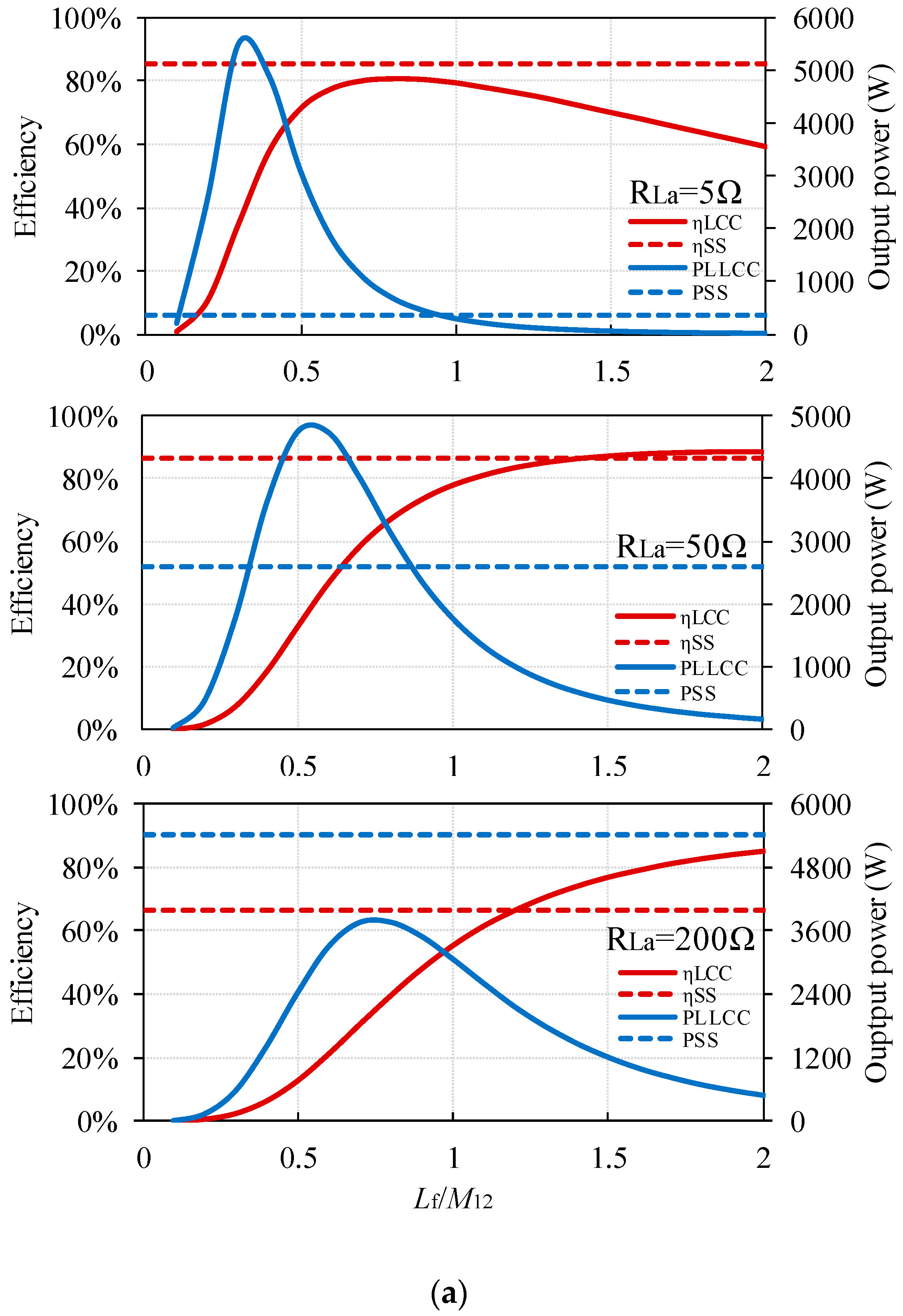
Clearly, the resistance of the coils and capacitors cannot be neglected when arriving at an accurate estimation of system performance. To determine the effects of the additional LCC components, simulation models for the SS-WPT system and the LCC-WPT system are built up using MATLAB/Simulink, as the MATLAB/Simulink has a rapid accelerator function which can greatly reduce the simulation time. The two WPT system models are based on the whole WPT system models as shown in Figure 1a and Figure 2a. In the simulation, the load resistance is set to be 5 Ω, 50 Ω and 200 Ω to provide different conditions. The other simulation parameters for the SS-WPT and LCC-WPT system have been listed in Table 2; it should be noticed that the parasitic resistance of the components are not exactly equal to practical values, because the combination of the compensation capacitor tank will be tuned to satisfy Equations (5) and (20). In order to have a more precise and meaningful consideration of the parasitic resistance of the compensation components, except for the previous assumption, another assumption is made in that all the compensation capacitors have the same parasitic resistance, and all the inductors have the same quality factor. Therefore, when the compensation inductor changes, even though the ESR of the inductor will vary, the quality of the inductor will keep constant, which is an important parameter when considering the system efficiency. Also, because the transmit and receive coils are fixed, therefore, the quality factor of the coils is treated as the benchmark, and then a meaningful ESR for the additional compensation inductor can be derived. The results are plotted as in Figure 6 under different assumptions.
Figure 6 shows the simulation schematics for particular operating conditions. Firstly, it can be seen that both these two assumptions can provide similar results on the analysis of the impacts caused by the Lf on the WPT system performance particularly on the system efficiency, the difference between these two results are mainly on the system output power which is caused by the parasitic resistance of the Lf. Besides, it can also be found out that when the parasitic resistance of the system is considered in the simulation, the output power and the efficiency will not exactly equal to each other when Lf = M12 for the LCC-WPT system, therefore, the impacts caused by the parasitic in the system cannot be neglected.
Considering the output power, when the load resistance is small, such as 5 Ω in this simulation, when Lf = M12, the output power of the two systems could be very close to each other. But with the load resistance increasing, a smaller ratio of Lf/M12 is required to achieve the same output power. When the load resistance is too high, such as 200 Ω in this simulation, even the maximum output power of the LCC-WPT system cannot equal the SS-WPT system output power. Therefore, in order to achieve equal output powers for the SS-WPT system and the LCC-WPT system, the DC input voltage must be adjusted.
Regarding the system efficiency, the phenomena is opposite to the output power. When the load resistance is very small, the maximum efficiency of the LCC-WPT system is still lower than the SS-WPT system, and with an increase in Lf, the efficiency of the LCC-WPT system will decrease because of the losses caused by the parasitic resistance in the coil-system, which will occupy a large part of total power in the system. However, with the load resistance increasing, the equal efficiency points move towards a ratio of Lf/M12 = 1. As shown in the simulation results, when the load resistance is 200 Ω, the ratio of Lf/M12 is about 1.3 for the same efficiency of the two WPT systems.
Therefore, if the LCC-WPT system requires high efficiency, Lf should be sufficiently larger than the mutual inductance without sacrificing its power transfer capacity. If the LCC-WPT system needs to improve the power transfer capacity, Lf should be a suitable small value without considering the efficiency.
Similar simulations can be carried out to verify the analysis of the DC input voltage tuning method presented in Section 3.2, when the LCC-WPT system aims at delivering the same power to the same load with the same transmit and receive coils as the SS-WPT system. With the same two assumptions, the results are shown in Figure 7, containing good consistency with Figure 5.
In order to investigate why a higher efficiency is possible for the LCC-WPT system, a simulation is made for a particular condition, the results of which are shown in Table 3. In this simulation, the DC input voltage of the LCC-WPT system in adjusted to achieve the same output power as the SS-WPT system, with a load resistance of 100 Ω, and DC input voltage of the SS-WPT system at 50 V. It can be seen from Table 3 that when Lf has a large enough inductance, the LCC-WPT system efficiency will be higher than the SS-WPT system, as the primary side total loss is greatly reduced whilst there is only a relatively small increase in loss in the secondary side. As Lf/M12 increases, the load resistance reflected to the input increases, reducing driver current and increasing driving voltage.
From the theoretical analysis and the simulation, it can be seen that one advantage of the SS-WPT system is that it needs fewer components than the LCC-WPT system. But with the LCC-WPT system, from the theoretical analysis and the simulation, it is seen that higher efficiency can be achieved with an optimum choice of Lf. It was also shown in the previous analysis that when Lf changes, the output power of the LCC-WPT system will differ greatly and can be several tens of times that of the SS-WPT system output power with the same DC input voltage. But under this condition, high voltage stresses are placed on system components.
Therefore, in order to investigate at a greater depth the advantages and disadvantages of the SS-WPT system over the LCC-WPT system with various Lf, and validate the mathematical and simulation analyses conducted previously, a practical SS-WPT system and three LCC-WPT systems with different Lf designs are constructed, with Lf set at M12, 1.5 M12, 2 M12, as the LCC-WPT system is designed for a higher system efficiency than the SS-WPT system, which means the Lf cannot be smaller than M12, and all the experiments and conclusions are based on this precondition. The LCC-WPT system and the SS-WPT system are compared with various loads resistance values, as load resistance can change the output power of the system without changing other parameters to provide different load conditions. The DC input voltage is adjusted to provide the same output power for the LCC and SS WPT systems. More aspects are analysed in detail with the experimental setup introduced in Section 4, such as the system efficiency, the maximum voltage stress on components, and the losses in the MOSFETs (metal oxide semiconductor field effect transistor) with various load resistances.
4. Comparison between the LCC and the SS-WPT Systems
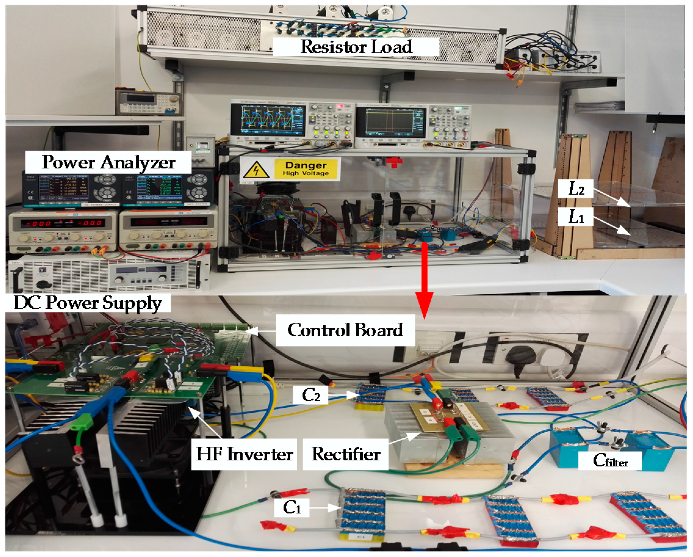
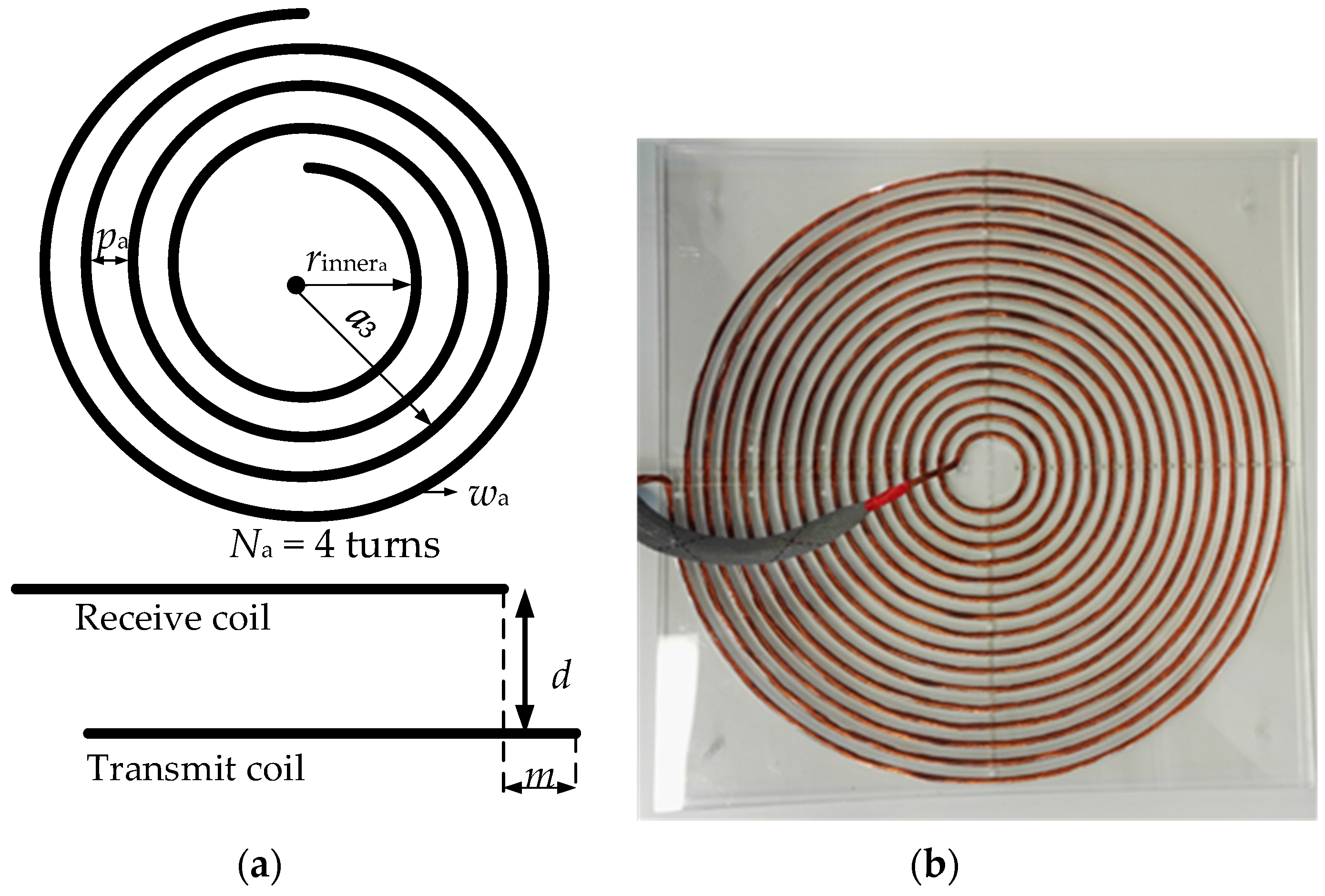
The experimental setup shown in Figure 8 is constructed to verify the previous analysis. The configuration of transmit and receive coils is shown in Figure 9, and the specifications of the coil structure are as shown in Table 4.
In the experiments, EA-PS 81000-30 DC Power Supply is used to supply power to the whole system. The H-Bridge inverter composed by four SiC power MOSFETs S1–S4 (CREE C2M0040120D) feeds the required high frequency excitation power to the primary coil-system. The secondary coil-system delivers power to the load resistors via a bridge rectifier, which is formed by four SiC diodes (C4D20120) and a filter capacitor. Two NOORMA 4000 Power analyzers are used to measure the DC supply power, driver output power, rectifier input power, and the load power. A 100 MHz oscilloscope is used to observe the measured voltages and currents. The parameters used in the SS-WPT system are shown in Table 5; Table 6 shows the specifications of the three different designs of the LCC-WPT systems with = M12, = 1.5 M12, = 2 M12. Subscript a, b and c represent the three different designs of the additional compensation inductor. It should be noticed that because of the errors existing in the fabrication of the additional inductor, the actual Lf is not exactly equal to the designed value, and is slightly larger than the mutual inductance. Lf is the additional series connected compensation inductance in the form of an air-cored inductor as shown in Figure 10. Although air-cored inductors are suitable for an experimental setup, they have the disadvantage of an unconfined magnetic field and therefore must be kept away from metal surfaces to avoid induced currents and variation in inductance. For a practical system, a gapped ferrite core or a ring core using a low permeability, low loss material such as “Genalex” would be preferable. Cf is the additional compensation capacitor parallel connected between Lf and the original SS-WPT system; C is the original compensation capacitor used in the SS-WPT system but the capacitance has been adjusted in the LCC-WPT system. The load resistance will vary from 5 Ω to 200 Ω to provide a wide range of load conditions, and this load resistance range can be found in existing research on WPT systems operating at around 85 kHz resonant frequency; i.e., in [23], the load resistance is 24.24 Ω; in [24], the load resistance is 30.5 Ω; in [25], the load resistance is 177.6 Ω; in [26], three load resistance values are selected as the load, 15 Ω, 50 Ω, and 200 Ω. The coil to coil vertical displacement is set at 150 mm, giving coupling coefficient of 0.27.
Based on this two-coil WPT experimental setup, the previous analysis can be verified through experiments. A comparative analysis between the LCC-WPT system and the SS-WPT system is conducted as follows.
4.1. Effects of Load Resistance
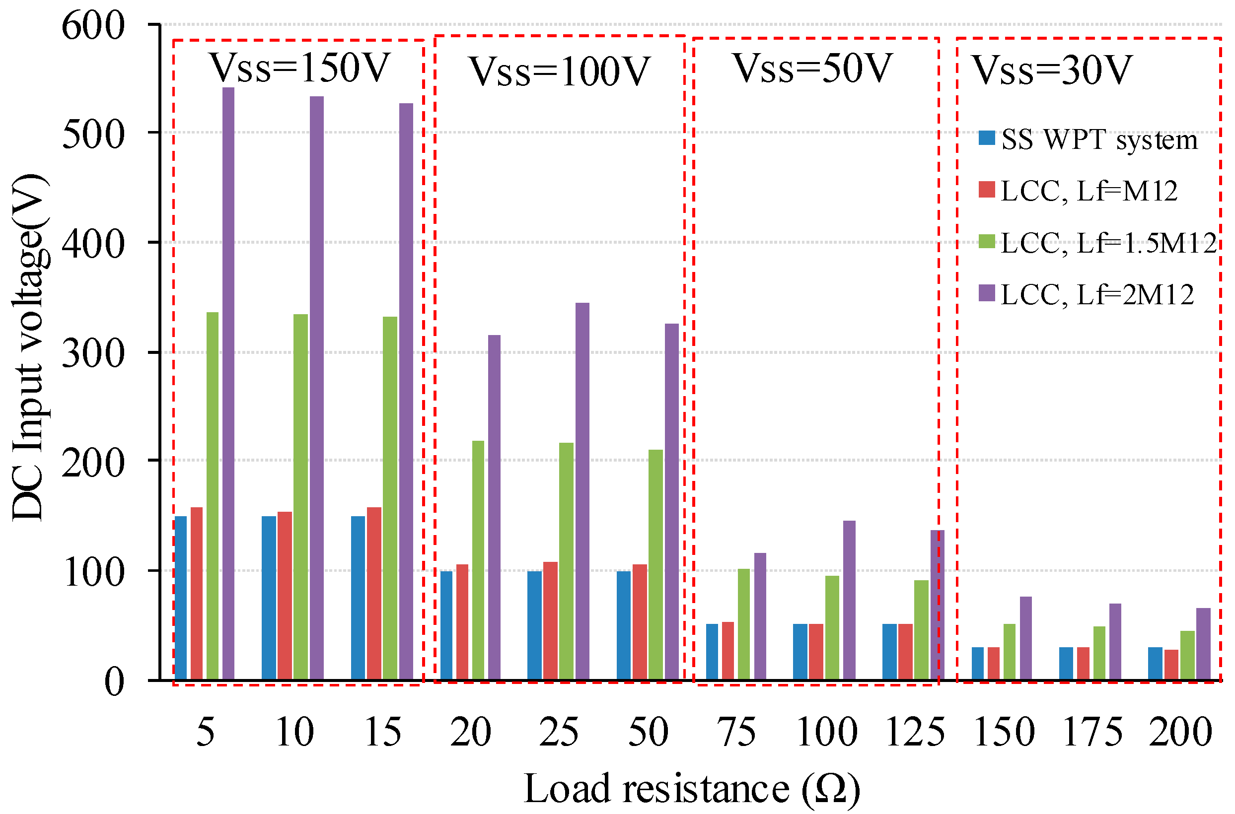
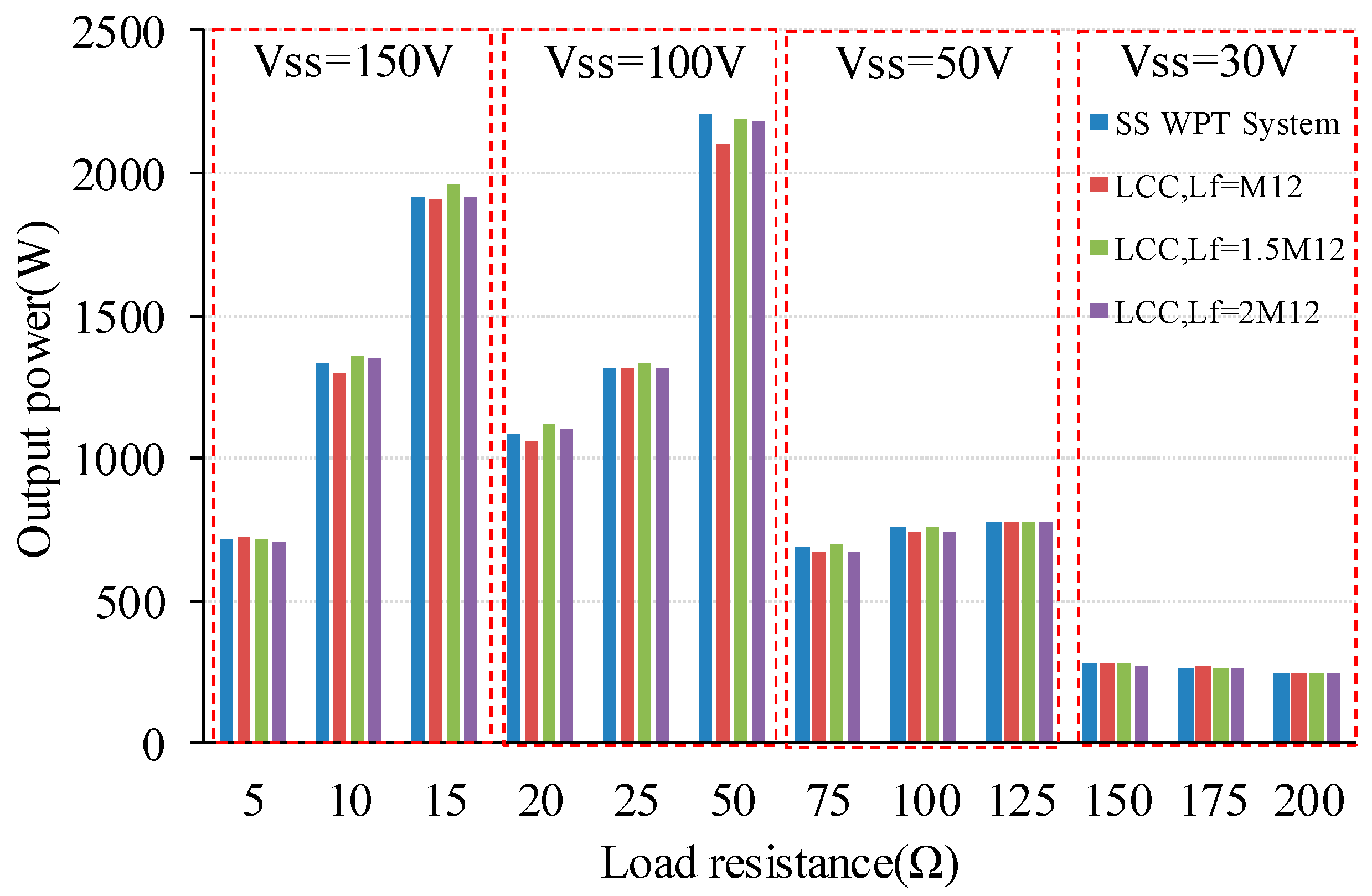
The difference in the effect of variation of load resistance on the SS and LCC WPT systems is considered in this section. The range of the load resistance is 5 Ω to 200 Ω with the coils set 150 mm apart to give a coupling factor of 0.27. As the ratio of Lf to M12 is increased, it is seen that for the same load power as the SS-WPT system into the same load resistance, the input voltage to the LCC-WPT system needs to increase, as shown in Figure 11, which gives experimental results over the range of load resistances, for example, when the load resistance is 5 Ω, the input DC voltage will be 540 V in the LCC-WPT system when Lf = 2 M12, which is nearly four times to the input DC voltage in the SS-WPT system. Tests were carried out at progressively lower input voltage with the increase in load resistance to keep stress on driver components within safe limits and VSS marked in the top of each load resistance range in the followed figures stands for the DC input voltage of the SS-WPT system. The corresponding power levels are shown in Figure 12, where by adjustment of the driver voltage, the load power for all four system conditions is brought to a very similar level.
As system efficiency is an important consideration for the WPT system, and according to Equations (31)–(38), the system efficiency is related to the equivalent resistance of the inverter and DC power supply; however, RS will vary slightly in different system operating conditions, therefore, the coil-to-coil efficiency is considered firstly as the comparison target which has the same trends of the overall system efficiency, and system overall efficiency will also be presented as a supplement. In the expression used to calculate the power and efficiency of the two systems, VS is replaced by U1, and RS is set to be zero to be removed from the Equations (9)–(11) and (36)–(38), then it can be found that the output voltage of the inverter and the equivalent resistance RS will not affect the coil-to-coil efficiency. From Figure 13, it is seen that coil-to-coil efficiency and the system overall efficiency have the same trends, and it can also be found out that the efficiency trends are similar between the SS-WPT system and the LCC-WPT systems. As the load resistance increases, the system efficiencies increase at first and then decrease. When Lf is close to the mutual inductance, the LCC-WPT system efficiency is nearly equal to the SS-WPT system efficiency, as analysed in Section 3.1. But when the load resistance is smaller than a critical point (25 Ω in this work), the system efficiency of the SS-WPT system is higher than the LCC-WPT system due to higher losses in the parasitic resistances of the LCC-WPT system, as analysed in Section 3.3. With the increase in the load resistance, the LCC-WPT system can show a higher system efficiency than the SS-WPT system at higher values of Lf. Also, the decline of the system efficiency as the load resistance decreasing is slower with higher Lf.
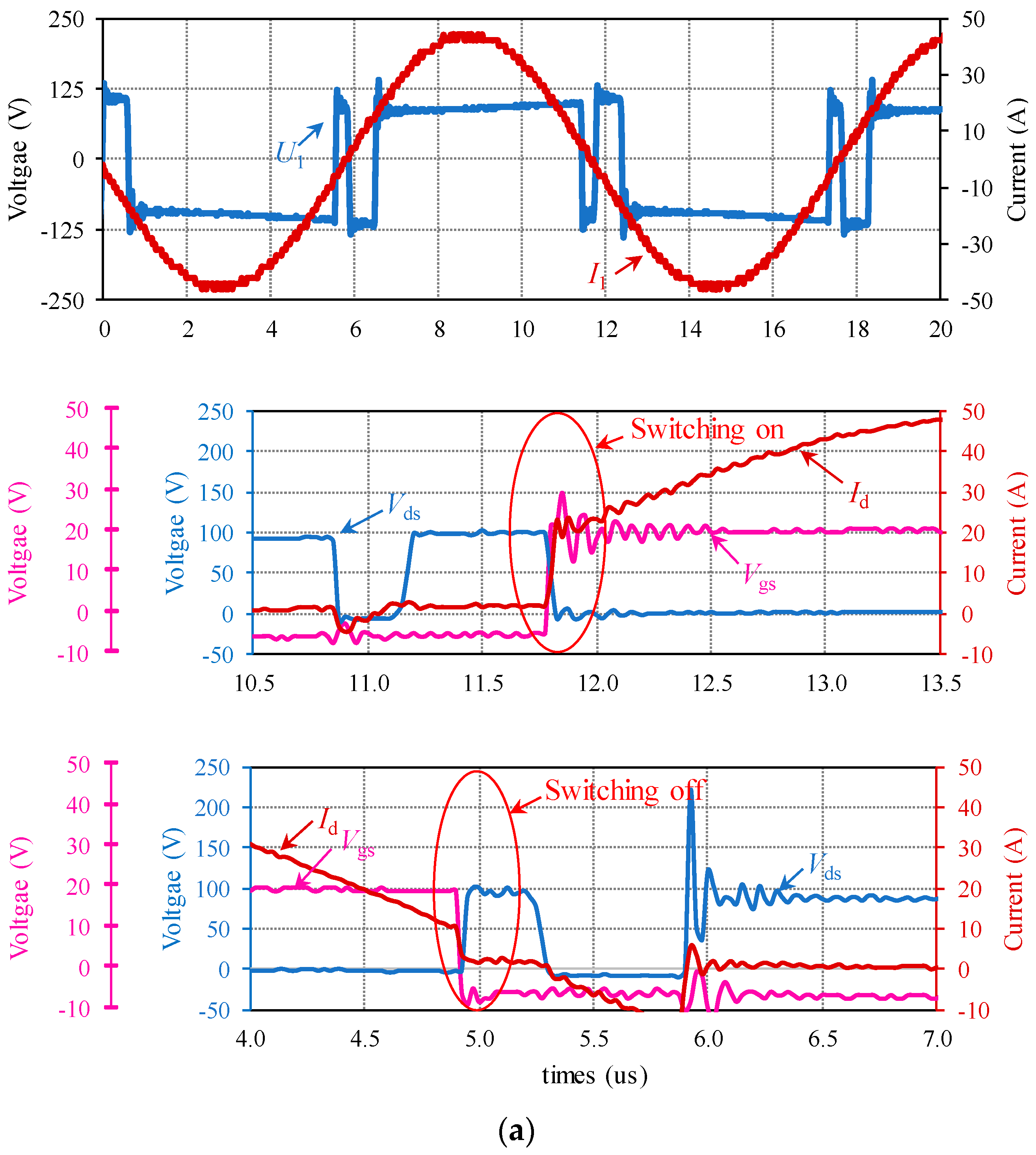
For a high frequency WPT system, the losses in the switching devices in the inverter and rectifier should also be considered for system safety, and also for improving the system overall efficiency. For the rectifier, SiC Scotty Diodes are used in this work which lead to a high efficiency for the rectifier. Therefore, only MOSFET losses produced in the inverter are analysed in this work. Figure 14 shows the output voltage and current waveforms of the inverter and the MOSFET switching state in the SS-WPT system and the LCC-WPT system when Lf = 2 M12 with 50 Ω load resistance and both with 100 V DC input voltage. It was found that the MOSFETs of the inverter operated at a hard-switching state in both the SS-WPT system and the LCC-WPT system.
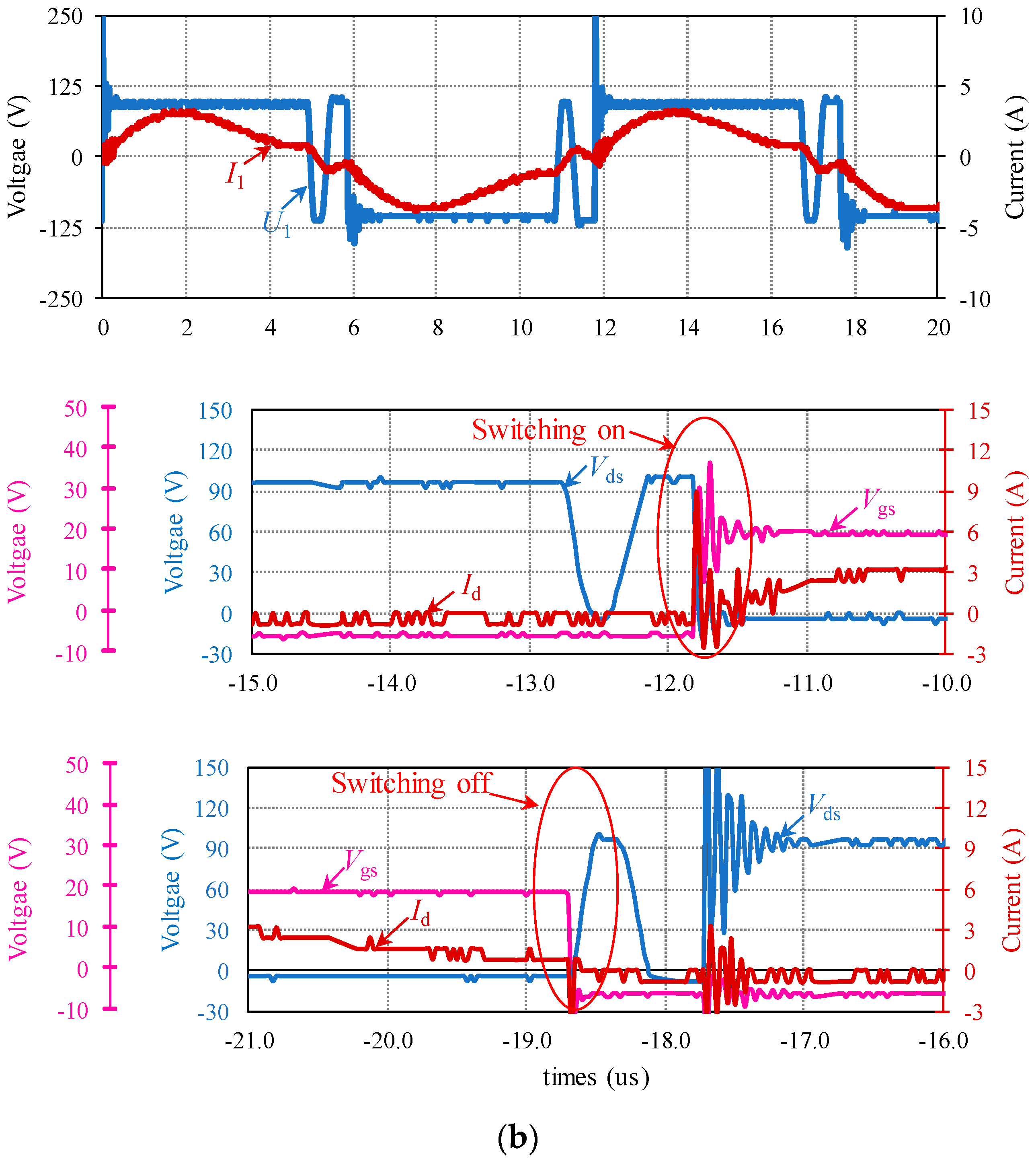
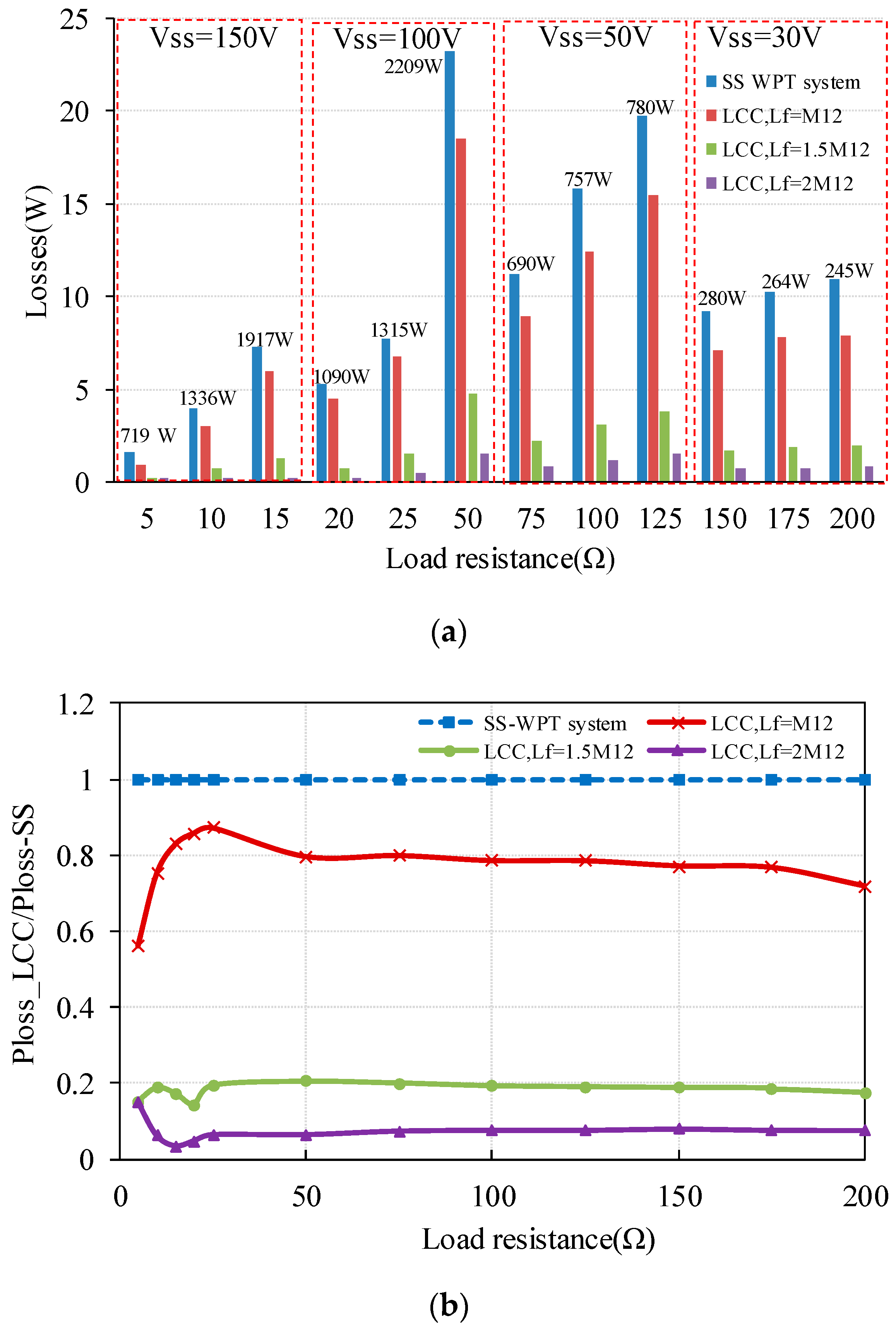
Figure 15a shows the losses produced by a single MOSFET in the inverter with the WPT system output power indicated on the bars and Figure 15b describes the radios of the MOSFET losses in the LCC and SS WPT systems (PLoss-LCC/PLoss-SS). From Figure 15b, it is seen that the MOSFET losses are always higher in the SS-WPT system compared to the LCC-WPT system; and for the three LCC-WPT systems, as Lf is increased, MOSFET losses can be further reduced. In the experiments, for the lowest output power condition, the load resistance is 200 Ω with 245 W output power, the LCC-WPT system reduces the MOSFET losses in the SS-WPT system from 11 W to 0.825 W when Lf = 2 M12. When the load resistance is 50 Ω, the WPT system will output the highest power in this work at 2209 W, and at this condition, for the SS-WPT system, the MOSFET loss is 24 W while the MOSFET loss is only 1.5 W when Lf = 2 M12 in the LCC-WPT system. The MOSFET loss can be reduced is because when the load resistance of the LCC-WPT system is the same as the SS-WPT system, due to the increase in the DC input voltage (Figure 11) and the increase in the system efficiency (Figure 13), the output current of the inverter is greatly reduced with higher inductance of Lf, which in turn greatly reduces the losses in the MOSFETs.
Stresses on compensation capacitors used in WPT systems need to be carefully considered for reliability. In terms of the voltage stress on the components, this paper only focuses on the voltage on the compensation capacitors because at high frequency, the voltage rating of the film capacitors used in these experiments rapidly declines with frequency, as shown in Figure 16. For a 47 nF, film capacitor (EPCOS, B32653), the alternating current (AC) voltage rating will decline from 500 V to 150 V at 105 Hz, which requires series/parallel combinations of capacitors to keep within ratings.
Therefore, as the voltage on the compensation capacitor increases, the volume it occupies and also its cost increases. It is useful therefore to compare capacitor voltages between the two systems, focusing on whichever component in each system is subjected to the highest voltage. The voltage marked on the bars in Figure 17a stands for the input DC voltage in the SS-WTP system, and Figure 17a gives the maximum capacitor voltage of the four WPT system under different operating conditions. It can be seen that when the load resistance is 5 Ω with 150 V input voltage, the LCC-WPT system can help reduce the maximum capacitor voltage in the SS-WPT system from 456 V to 350 V when Lf = M12, while with Lf = 2 M12, the maximum capacitor voltage in the SS-WPT system is smaller than the LCC-WPT system. When the load resistance increases to 200 Ω with 30 V input voltage, for the SS-WPT system, the maximum capacitor voltage is 700 V and the maximum capacitor voltage is only 200 V when Lf = 2 M12, and when Lf = M12, the maximum capacitor can be reduced to 470 V.
It should be noted that with the load resistance increasing, the pre-set DC input voltage is decreasing in the experiments. The ratios of the maximum capacitor voltage of the LCC-WPT system and the SS-WPT system (UC-LCC/UC-SS) are plotted in Figure 17b. Obviously, for the LCC-WPT system, except when Lf = 2 M12, the maximum capacitor voltage is reduced compared to the SS-WPT system. Also, with the load resistance increasing, even when Lf = 2 M12, the LCC-WPT system can help to reduce the capacitor voltage. To the three different Lf designs LCC-WPT system, when the load resistance is smaller than a certain value (20 Ω in this paper), lower inductance of the additional inductor Lf can lead to a lower capacitor voltage. As the load resistance increases to higher than 50 Ω, higher inductance of the additional inductor Lf can more effectively reduce the capacitor voltage, even with higher DC input voltage compared to the SS-WPT system (Figure 11).
As a conclusion, with the same transmit and receive coils, for a low resistance load, the SS-WPT system can achieve higher coil system efficiency but has to sustain higher capacitor voltage and higher MOSFET losses than the LCC-WPT system. For a high resistance load system, the LCC-WPT system can effectively improve the system efficiency compared to the SS-WPT system. The higher the inductance of the additional inductor, the more slowly will the system efficiency declines with increasing load resistance. Also, a higher Lf design can achieve lower MOSFET losses and can greatly decrease the capacitor voltage, but the input DC voltage will be correspondingly higher.
4.2. Ability to Resist the Misalignment
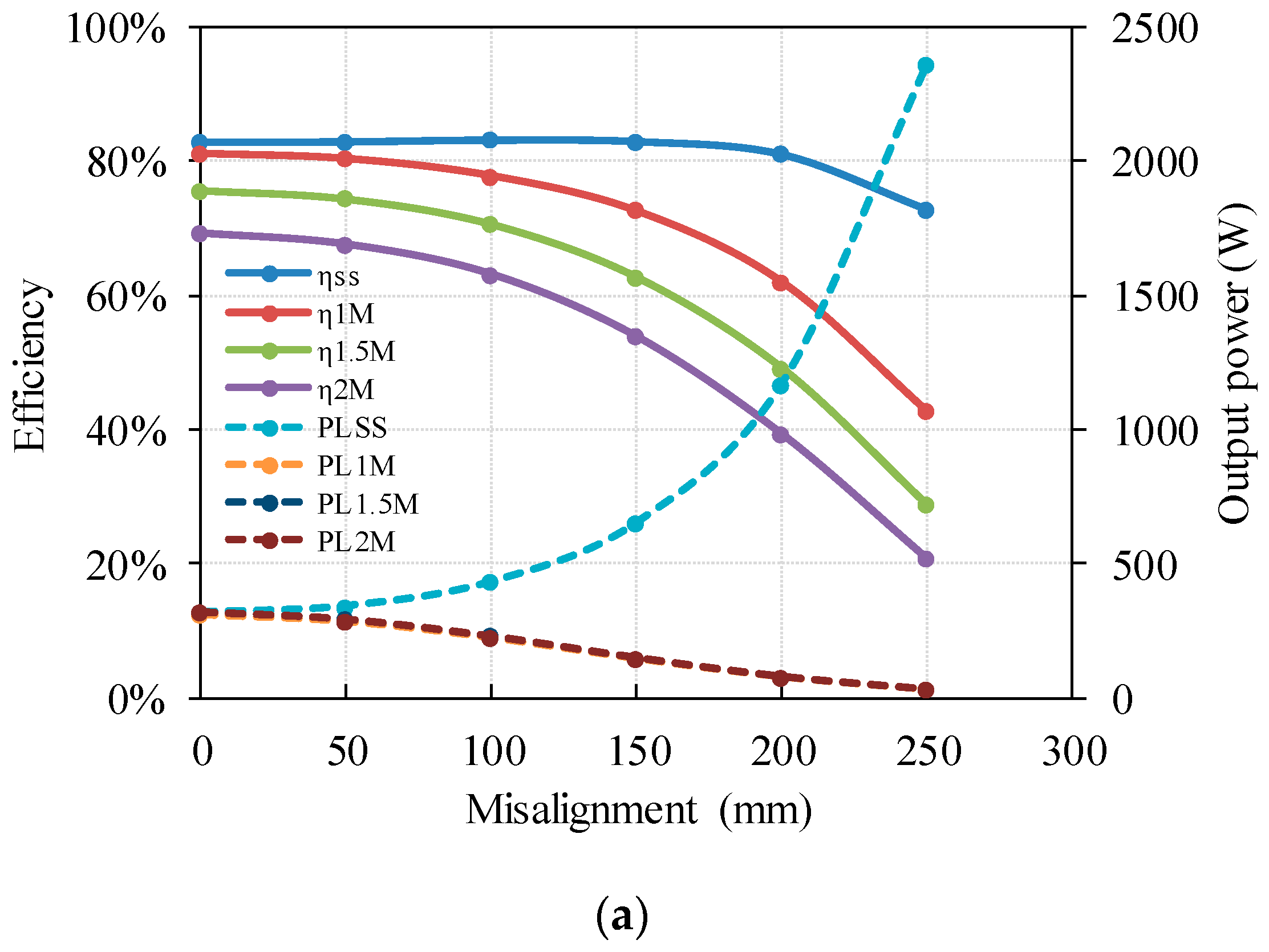
The coupling coefficient, k, represents the degree of electromagnetic coupling between the transmit and receive coils. It depends on the structure of the two coils and their relative position. The structure of the coils is normally fixed, but the relative position may vary in practice to allow the load to be placed at any position above the charging surface in a wireless battery-charging platform. Therefore, a WPT system needs to have a certain ability to resist any misalignment; so, in this part, the impact of misalignment is analysed. The coil-to-coil vertical distance is also 150 mm, to be the same as with the previous analysis. The coil-to-coil horizontal misalignment is set to change from 0 to 250 mm, which is m in Figure 9, and the maximum misalignment is slightly smaller than the outer radius of the coil, and will change in 50 mm steps. The same three different load resistances as used previously with the coils perfectly aligned are used. When the load resistance is 5 Ω, the efficiency of SS-WPT system is higher than LCC-WPT system; when the load resistance is 25 Ω, the efficiency of SS-WPT system can achieve approximately equal efficiency to the LCC-WPT system in the experiments, and a higher load resistance 50 Ω is selected as the last condition where the efficiency of the LCC-WPT system is higher than the SS-WPT system as shown in Figure 13.
The experimental results for misalignment are shown in Figure 18. When the two coils are in alignment, the DC input voltage to the LCC-WPT system is adjusted to achieve the same output power as the SS-WPT system. The DC input voltage is then held constant with changes in alignment.
Considering the system output power, it can be found from the comparison experiments, that no matter what the load condition is, there will be a critical coupling coefficient point in the SS-WPT system where the output power reaches a maximum and will change according to the load resistance. But it should be noticed that the actual peak output power can be achieved in the SS-WPT system did not occur in the experiments because of the large misalignment step design; as in Figure 18b, the actual maximum output power will occur between 200 and 250 mm, but not exactly at 200 mm, and then the system overall efficiency will be 50% and the peak output power will be even higher than the power achieved at 200 mm. In contrast, the LCC-WPT system shows a monotonic decrease in output power with misalignment at the values of Lf and load resistance used in these tests. As a conclusion, with the increase in the misalignment distance, the output power of SS-WPT system will increase firstly and then decrease, but for the LCC-WPT system, the output power will continuously decrease. The load power of the LCC-WPT system does not rise above that when the coils are perfectly aligned, avoiding a possibly dangerous peak in power that may occur with the SS-WPT system.
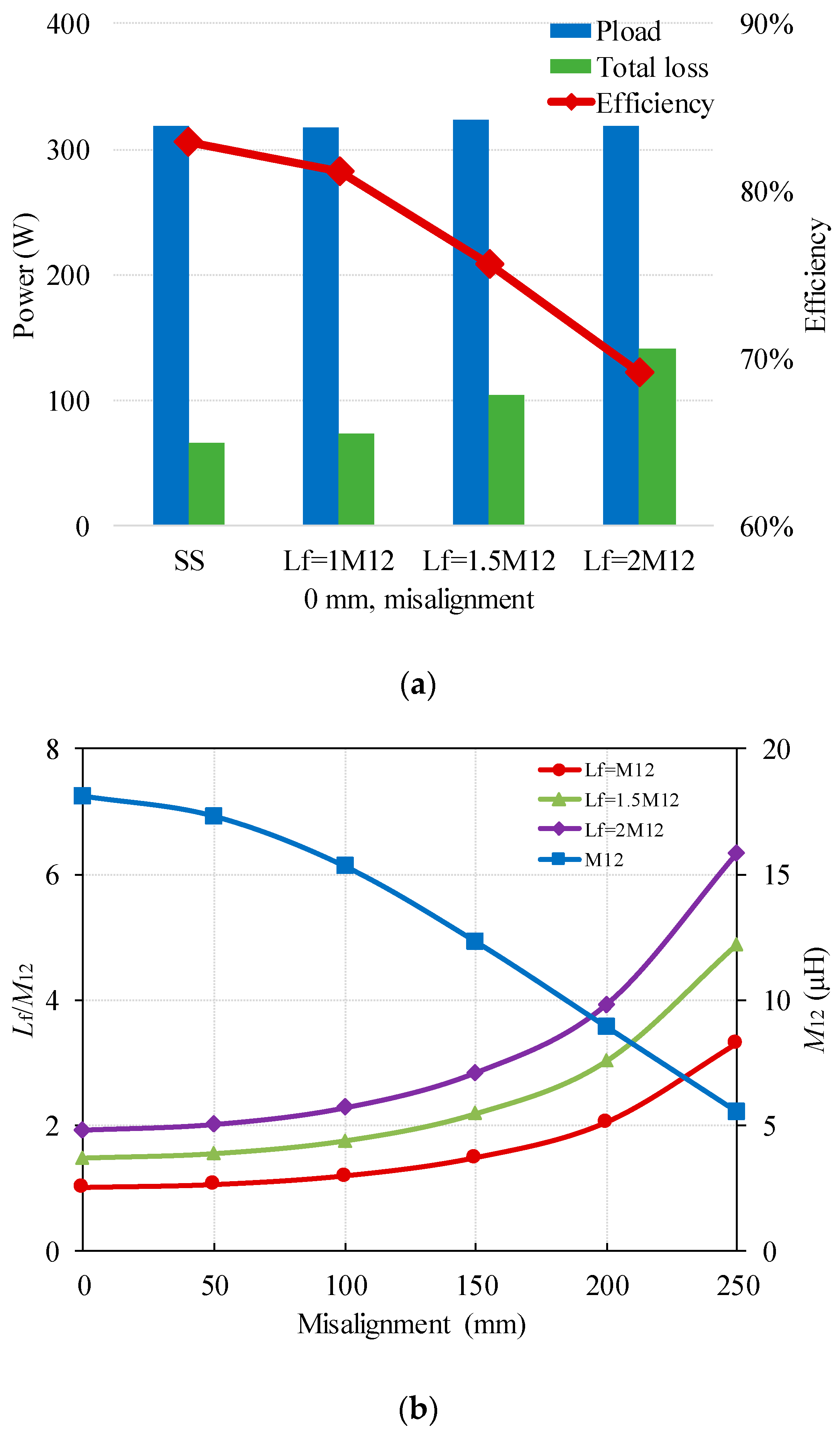
Regarding the system efficiency, the efficiency of the SS-WPT system and the LCC-WPT system will both decrease with misalignment increases, but different load resistances will affect the system efficiency performance against possible coil misalignment. It can be seen from Figure 18a that when the load resistance is small (5 Ω), the efficiency of the SS-WPT system is always higher than the LCC-WPT system, and the SS-WPT system shows a better performance against the possible coil misalignment than the LCC-WPT system. It has been shown in Section 4.1 that when the load resistance is small, higher Lf to M12 ratios lead to lower system efficiency when the coils are perfectly aligned (Figure 13), that is due to the increase in circuit losses with increase in Lf:M12 ratio, as can be seen as Figure 19a. With misalignment, the mutual inductance is reduced in proportion to the degree of misalignment as the blue curve shown in Figure 19b, causing the relative numerical difference between the Lf and the mutual inductance to increase commensurately, i.e., a higher Lf to M12 ratio as shown in Figure 19b, and this accounts for progressively worse efficiency with misalignment of the LCC-WPT system when the load resistance is low.
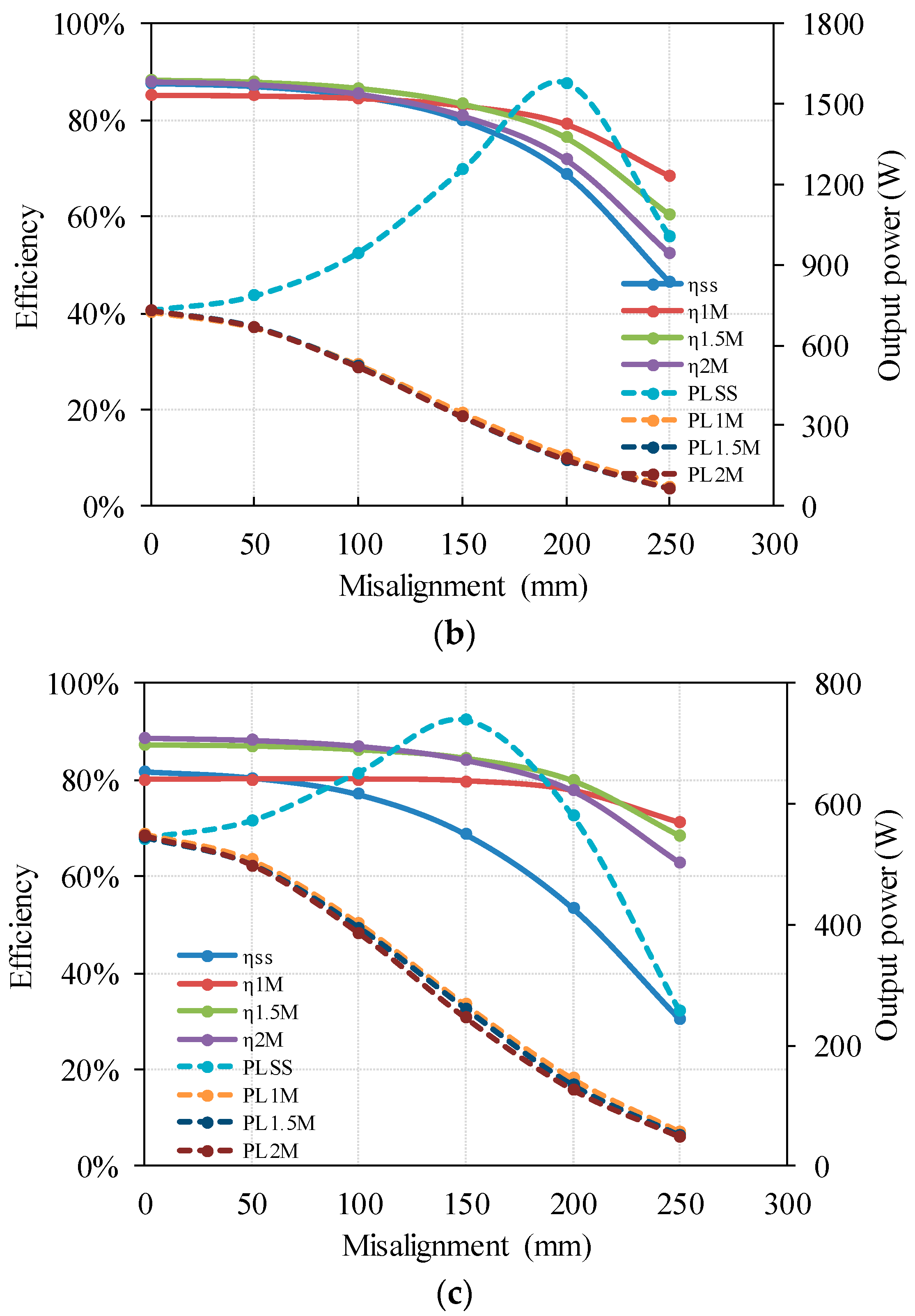
When the load resistance increases to the critical load resistance point (25 Ω), the advantage of the LCC-WPT system is seen. It can be found from Figure 18b that with increasing misalignment, the decline trend of the LCC-WPT system efficiency will be slower than that of the SS-WPT system. With 25 Ω load resistance, the initial efficiency of the SS-WPT system is still higher than the LCC-WPT system when the Lf = M12 but lower than that of the LCC-WPT system with higher Lf values, when misalignment increases to over 100 mm, all the three LCC-WPT systems show higher efficiency than the SS-WPT system. For systems with higher load resistance (50 Ω), this advantage increases, as shown in Figure 18c. The system efficiency of the SS-WPT system will decline from 82% to 31% as the horizontal misalignment is increasing from 0 to 250 mm while the LCC-WPT system can maintain the system efficiency in excess of 71% with Lf = M12, giving an advantage of 40% over that of the SS-WPT system at 250 mm misalignment. At 50 Ω load condition and Lf = 2 M12, the system efficiency can also be improved from 31% for the SS-WPT system to 63% with the LCC-WPT system, a system efficiency improvement of 32% is achieved.
Considering the effect of the inductance of the additional compensation inductor, lower values of Lf result in a more gradual drop in efficiency with misalignment. Therefore, with misalignment increasing to a critical value, a lower additional compensation inductor value can achieve higher system efficiency when the initial efficiency of the LCC-WPT system is higher than that of the SS-WPT system. For example, when the load resistance is 25 Ω, with m less than 150 mm, the efficiency of the three different Lf design LCC-WPT systems can achieve nearly similar efficiency, while with the misalignment increasing more than 200 mm, lower Lf values give higher efficiency as shown in Figure 18b And when the load resistance is higher (50 Ω in the experiments), as shown in Figure 18c, when the misalignment is less than 200 mm, higher Lf design in the LCC-WPT system can achieve higher efficiency; however, when the misalignment exceeds 200 to 250 mm, a smaller Lf design in the LCC-WPT system can achieve higher efficiency, as can be seen from the experiments, when Lf = 2 M12, the efficiency is 63%, while when Lf = M12, the efficiency is 71%. Meanwhile, the SS-WPT system can only achieve 31% efficiency with 250 mm misalignment and with 50 Ω load resistance.
5. Conclusions
The focus of this paper is to show the particular conditions allow an LCC compensation topology WPT system to be more energy efficient than a conventional SS compensation topology WPT system. The theory and design criteria for achieving this objective have been presented and verified by experiments, which have shown consistent results with the analysis.
To find the advantages and disadvantages of the SS and LCC compensation topologies and the impacts of the Lf in the LCC-WPT system, in this paper, three different Lf design double-sided LCC and SS compensation topologies were compared in terms of system efficiency, compensation capacitor voltage and power MOSFET loss for the same output power with variable load resistance. A DC input voltage adjusting method was used in order to ensure that the LCC-WPT system always operated at the same output power as the SS-WPT system. The results show that when the LCC-WPT system was designed for a higher energy efficiency than the SS-WPT system with the same coils, for a low resistance load, the SS-WPT system could achieve higher system efficiency but had to sustain higher capacitor voltage and higher device losses than the LCC-WPT system. For high resistance loads, the LCC-WPT system could effectively improve the system efficiency compared to the SS-WPT system. Higher Lf/M12 ratios could achieve higher system efficiency, reduce MOSFET losses and decrease the compensation capacitor voltages, but required an increase in the DC input voltage for the same output power. For lower values of load resistance, a lower Lf/M12 ratio gave higher efficiency in the LCC-WPT systems.
The LCC system has been shown to be more tolerant at higher values of load resistance of misalignment and did not show the same sharp rise in load power as with the SS-WPT system when misalignment set the coupling factor at the critical coupling point. Under low load resistance conditions, the SS-WPT system could provide higher efficiency when misalignment occurred, but could produce an undesirable power peak. At higher load resistance conditions, the LCC-WPT system could show higher system efficiency and avoid system damage caused by the over power of the SS-WPT system when misalignment occurred, and the decline trends of the LCC-WPT system efficiency along the misalignment were much slower than the SS-WPT system. In this work, the LCC-WPT system could keep the system efficiency in excess of 71%, which showed a 40% system efficiency improvement compared to the SS-WPT system with 50 Ω load resistance when the coils had a 250 mm horizontal misalignment.
Acknowledgments
This work was supported by the China Scholarship Council.
Author Contributions
Xu Liu wrote the paper and designed the experiments; Lindsay Clare shared his experience and knowledge in inductive power transfer technology; Xibo Yuan shared his experience and knowledge in power electronics; Chonglin Wang analysed the simulation data; Jianhua Liu helped to perform the analysis with constructive discussions.
Conflicts of Interest
The authors declare no conflict of interest.
References
- Tesla, N. Apparatus for Transmitting Electrical Energy. U.S. Patent 1,119,732, 1 December 1914. [Google Scholar]
- Zhang, Z.; Chau, K.T.; Liu, C.; Li, F.; Ching, T.W. Quantitative analysis of mutual inductance for optimal wireless power transfer via magnetic resonant coupling. IEEE Trans. Magn. 2014, 50. [Google Scholar] [CrossRef]
- Tortora, G.; Mulana, F.; Ciuti, G.; Dario, P.; Menciassi, A. Inductive-based wireless power recharging system for an innovative endoscopic capsule. Energies 2015, 8, 10315–10334. [Google Scholar] [CrossRef]
- Senjuti, S. Design and Optimization of Efficient Wireless Power Transfer Links for Implantable Biotelemetry Systems. Master’s Thesis, University of Western Ontario, London, ON, Canada, 2013. [Google Scholar]
- Xue, R.F.; Cheng, K.W.; Je, M. High-efficiency wireless power transfer for biomedical implants by optimal resonant load transformation. IEEE Trans. Circuits Syst. I Regul. Pap. 2013, 60, 867–874. [Google Scholar] [CrossRef]
- Shekhar, A.; Prasanth, V.; Bauer, P.; Bolech, M. Economic viability study of an on-road wireless charging system with a generic driving range estimation method. Energies 2016, 9, 76. [Google Scholar] [CrossRef]
- Gao, Y.; Farley, K.B.; Tse, Z.T.H. A uniform voltage gain control for alignment robustness in wireless EV charging. Energies 2015, 8, 8355–8370. [Google Scholar] [CrossRef]
- Madawala, U.K.; Thrimawithana, D.J. A bidirectional inductive power interface for electric vehicles in V2G systems. IEEE Trans. Ind. Electron. 2011, 58, 4789–4796. [Google Scholar] [CrossRef]
- Shin, J.; Shin, S.; Kim, Y.; Ahn, S.; Lee, S.; Jung, G.; Jeon, S.J.; Cho, D.H. Design and implementation of shaped magnetic-resonance-based wireless power transfer system for roadway-powered moving electric vehicles. IEEE Trans. Ind. Electron. 2014, 61, 1179–1192. [Google Scholar] [CrossRef]
- Hoang, H.; Lee, S.; Kim, Y.; Choi, Y.; Bien, F. An adaptive technique to improve wireless power transfer for consumer electronics. IEEE Trans. Consum. Electron. 2012, 58, 327–332. [Google Scholar] [CrossRef]
- Lin, J.C. Wireless power transfer for mobile applications, and health effects. IEEE Antennas Propag. Mag. 2013, 55, 250–253. [Google Scholar] [CrossRef]
- Zhang, W.; Mi, C.C. Compensation topologies of high-power wireless power transfer systems. IEEE Trans. Veh. Technol. 2016, 65, 4768–4778. [Google Scholar] [CrossRef]
- Khaligh, A.; Dusmez, S. Comprehensive topological analysis of conductive and inductive charging solutions for plug-in electric vehicles. IEEE Trans. Veh. Technol. 2012, 61, 3475–3489. [Google Scholar] [CrossRef]
- Auvigne, C.; Germano, P.; Ladas, D.; Perriard, Y. A dual-topology ICPT applied to an electric vehicle battery charger. In Proceedings of the 2012 XXth International Conference on Electrical Machines, Marseille, France, 2–5 September 2012; pp. 2287–2292. [Google Scholar]
- Hsieh, H.I.; Huang, T.H.; Shih, S.F. An inductive wireless charger for electric vehicle by using LLC resonance with matrix ferrite core group. In Proceedings of the 2015 IEEE Applied Power Electronics Conference and Exposition-APEC, Charlotte, NC, USA, 15–19 March 2015; pp. 1637–1643. [Google Scholar]
- Samanta, S.; Rathore, A.K.; Member, S. A New Current-Fed CLC Transmitter and LC Receiver Topology for Inductive Wireless Power Transfer Application: Analysis, Design, and Experimental Results. IEEE Trans. Transp. Electr. 2015, 1, 357–368. [Google Scholar] [CrossRef]
- Li, S.; Li, W.; Deng, J.; Nguyen, T.D.; Mi, C.C. A Double-Sided LCC Compensation Network and Its Tuning Method for Wireless Power Transfer. IEEE Trans. Veh. Technol. 2015, 64, 2261–2273. [Google Scholar] [CrossRef]
- Pantic, Z.; Bai, S.; Lukic, S.M. ZCS LCC-compensated resonant inverter for inductive-power-transfer application. IEEE Trans. Ind. Electron. 2011, 58, 3500–3510. [Google Scholar] [CrossRef]
- Keeling, N.A.; Covic, G.A.; Boys, J.T. A unity-power-factor IPT pickup for high-power applications. IEEE Trans. Ind. Electron. 2010, 57, 744–751. [Google Scholar] [CrossRef]
- Li, W.; Zhao, H.; Deng, J.; Li, S.; Mi, C.C. Comparison Study on SS and double-sided LCC compensation topologies for EV/PHEV Wireless Chargers. IEEE Trans. Veh. Technol. 2016, 65, 4429–4439. [Google Scholar] [CrossRef]
- Campi, T.; Cruciani, S.; Maradei, F.; Feliziani, M. Near-Field Reduction in a Wireless Power Transfer System Using LCC Compensation. IEEE Trans. Electromagn. Compat. 2017, 59, 686–694. [Google Scholar] [CrossRef]
- Miller, J.M.; White, C.P.; Onar, O.C.; Ryan, P.M. Grid side regulation of wireless power charging of plug-in electric vehicles. In Proceedings of the 2012 IEEE Energy Conversion Congress and Exposition, ECCE, Raleigh, NC, USA, 15–20 September 2012; pp. 261–268. [Google Scholar]
- Moon, S.; Kim, B.C.; Cho, S.Y.; Ahn, C.H.; Moon, G.W. Analysis and Design of a Wireless Power Transfer System With an Intermediate Coil for High Efficiency. IEEE Trans. Ind. Electron. 2014, 61, 5861–5870. [Google Scholar] [CrossRef]
- Pevere, A.; Petrella, R.; Mi, C.C.; Zhou, S. Design of a high efficiency 22 kW wireless power transfer system for EVs fast contactless charging stations. In Proceedings of the 2014 IEEE International Electric Vehicle Conference, Florence, Italy, 17–19 December 2014. [Google Scholar]
- Kamineni, A.; Covic, G.A.; Boys, J.T. Analysis of Coplanar Intermediate Coil Structures in Inductive Power Transfer Systems. IEEE Trans. Power Electron. 2015, 30, 6141–6154. [Google Scholar] [CrossRef]
- Kurschner, D.; Rathge, C.; Jumar, U. Design methodology for high efficient inductive power transfer systems with high coil positioning flexibility. IEEE Trans. Ind. Electron. 2013, 60, 372–381. [Google Scholar] [CrossRef]
Figure 1.
SS-WPT system (a) whole system; (b) simplified model.
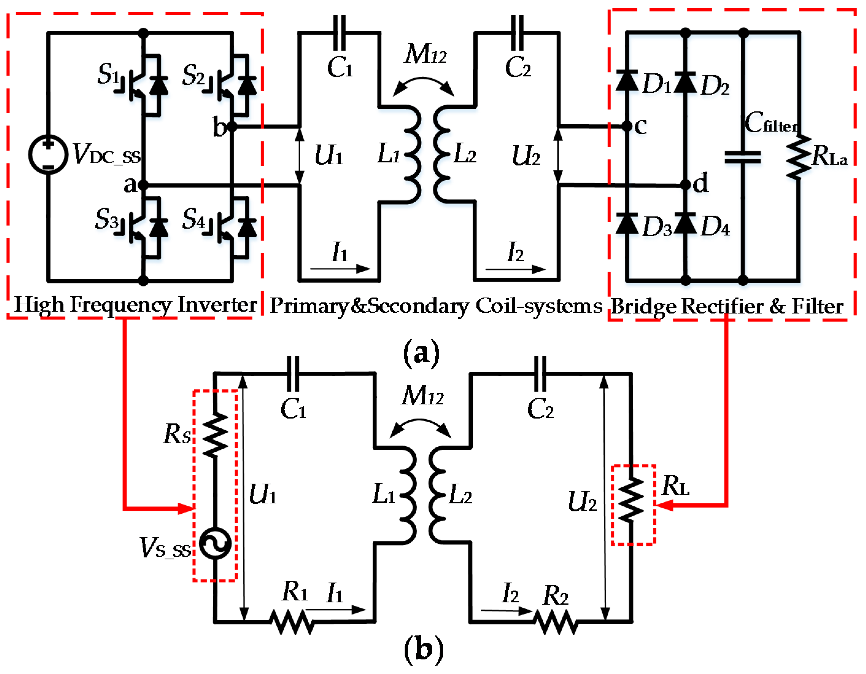
Figure 2.
LCC-WPT system (a) whole system; (b) simplified model.
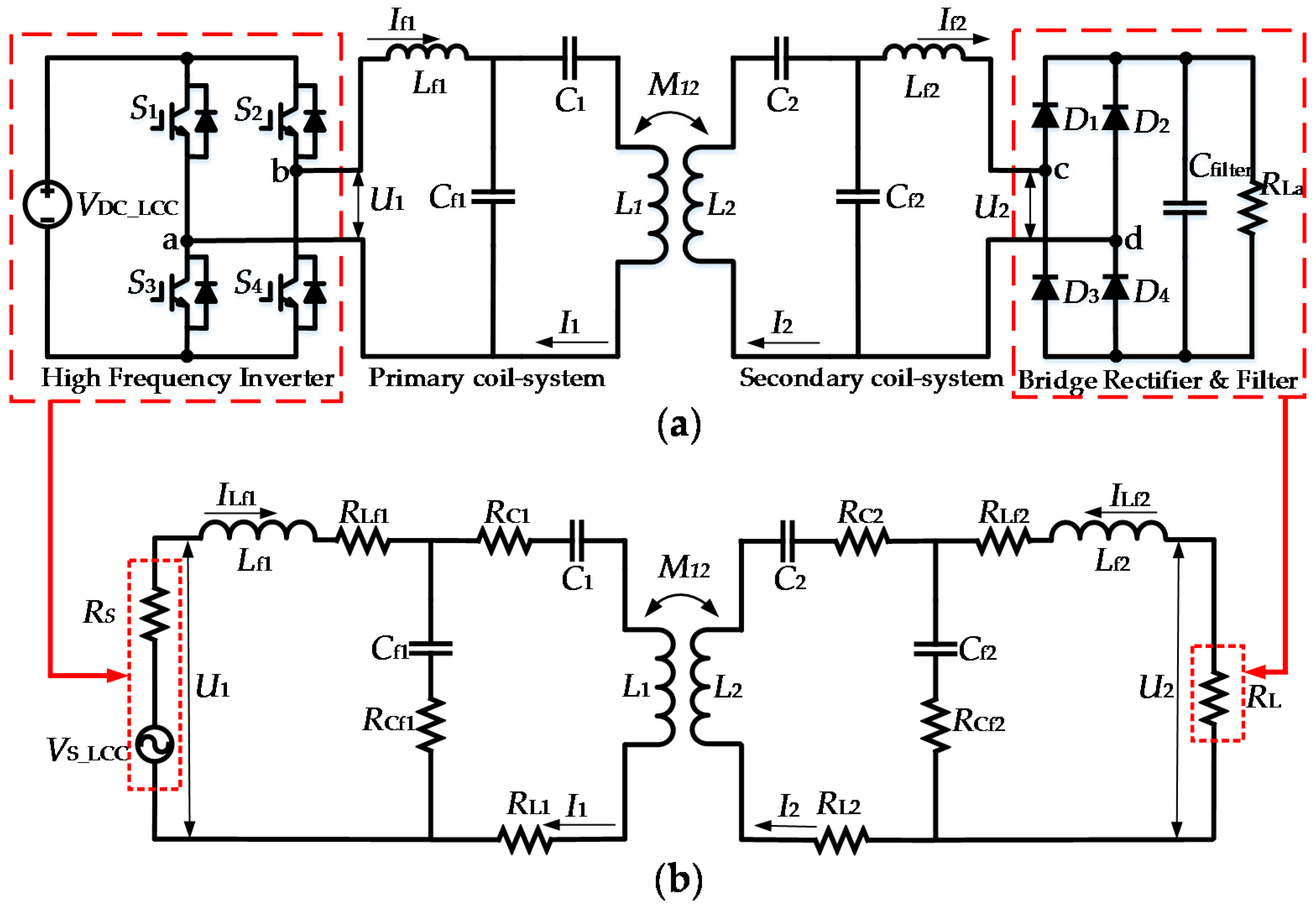
Figure 3.
Frequency response of the LCC system with Lf = 2 M12 and RL = 100 Ω.
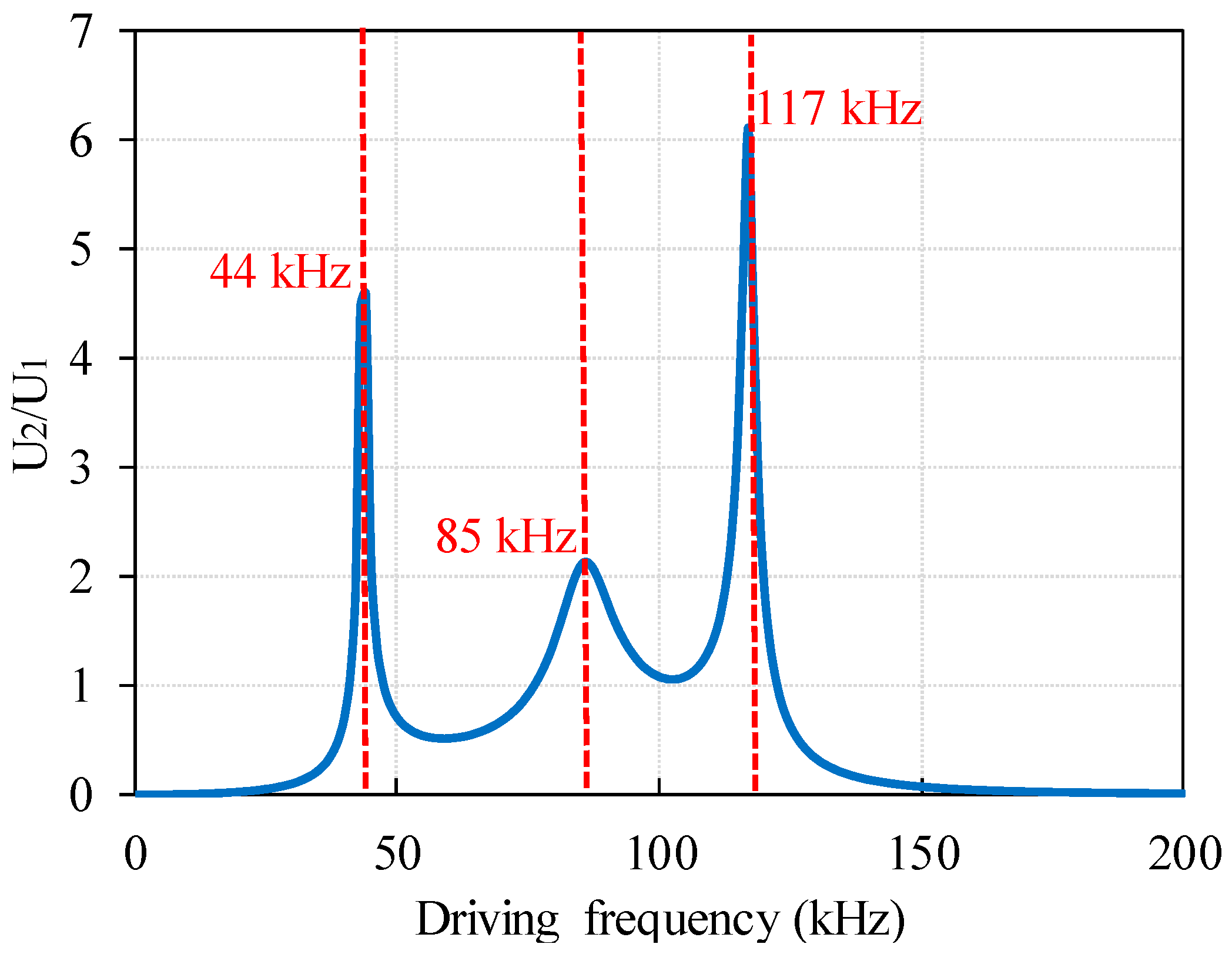
Figure 4.
Impacts caused by Lf on the LCC-WPT system performance.
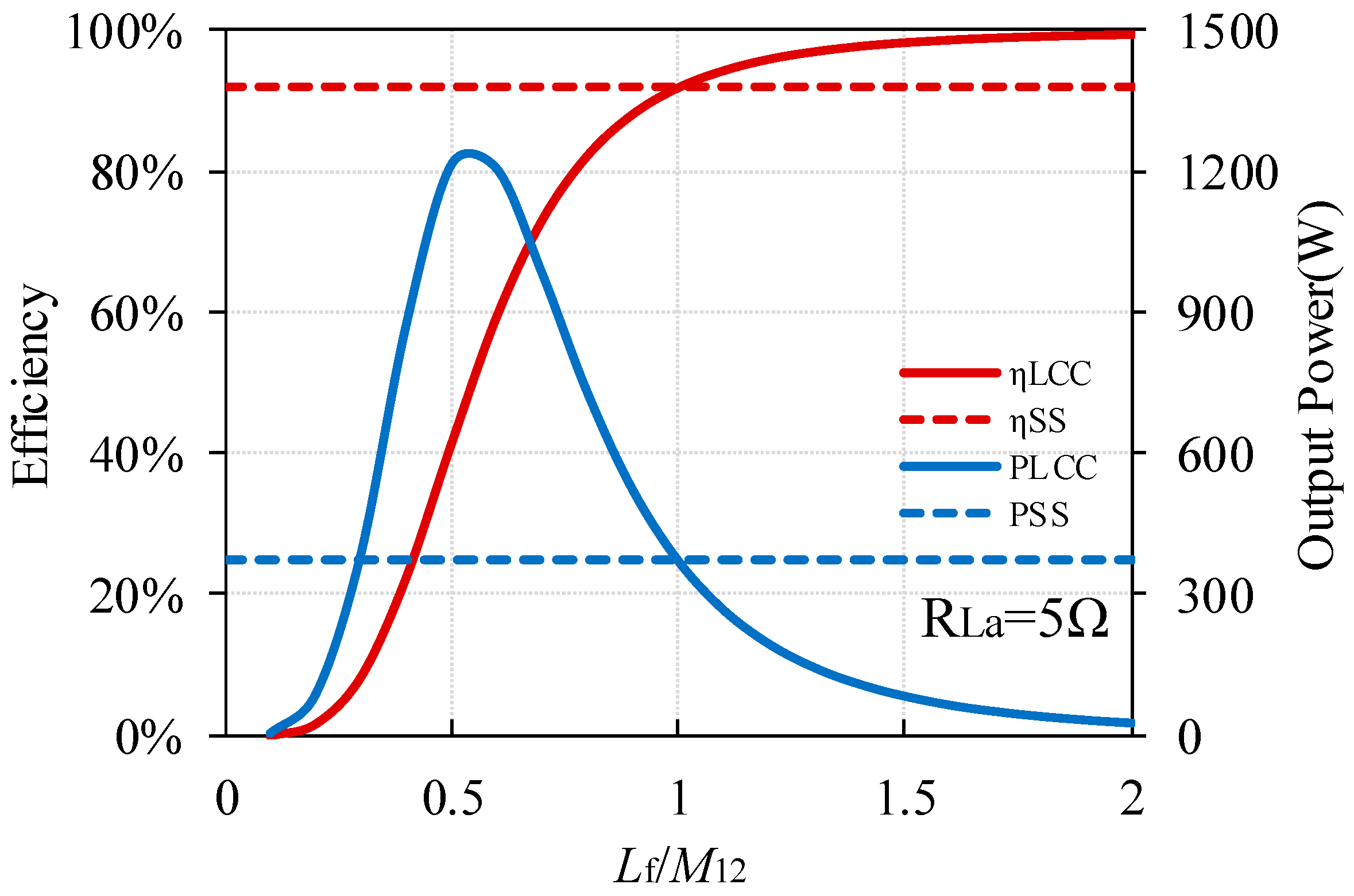
Figure 5.
Adjusted direct current (DC) input voltage of the LCC-WPT system when .
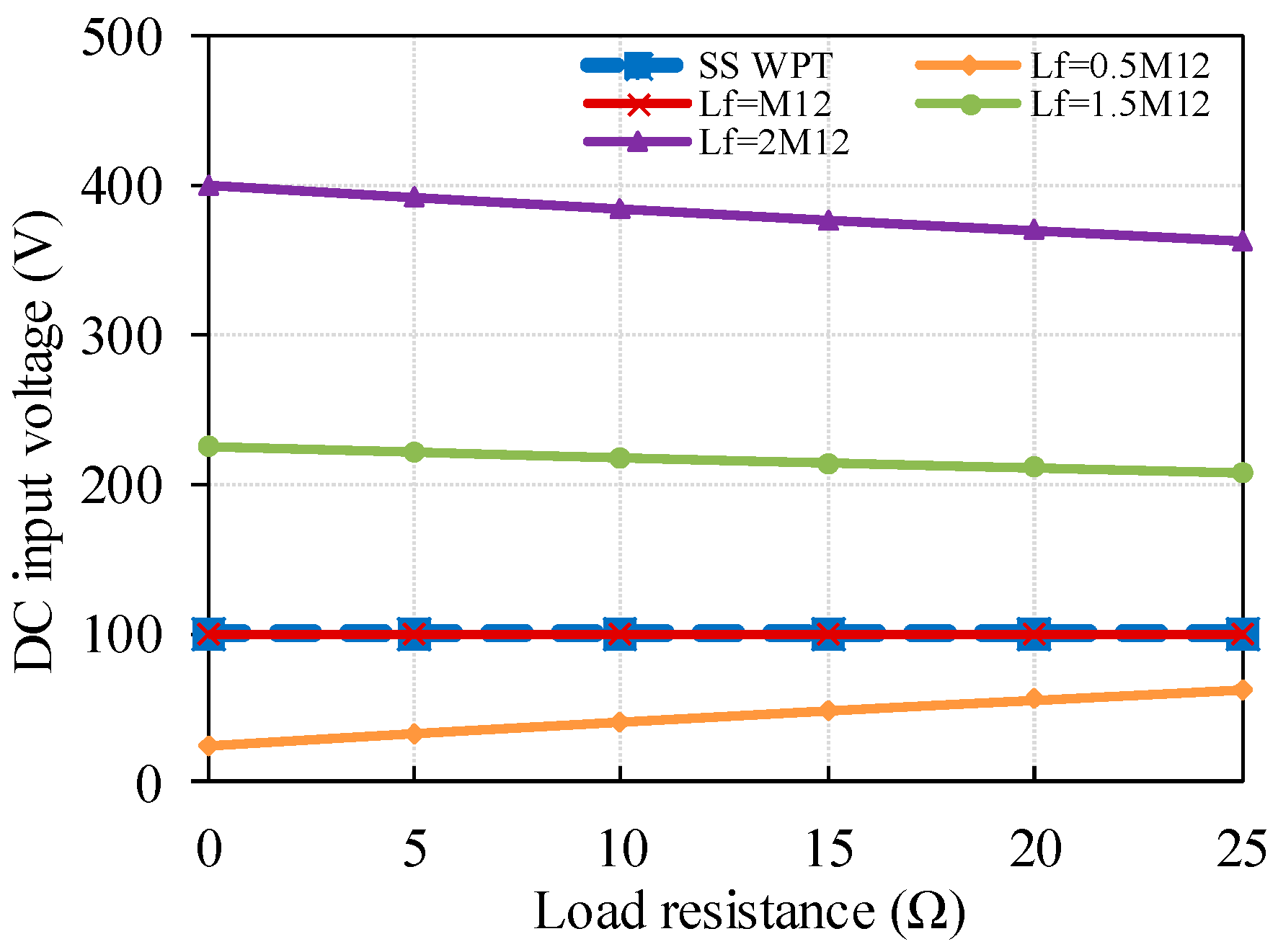
Figure 6.
Impacts caused by Lf on the LCC-WPT system: (a) identical ESR of all the compensation components; (b) identical ESR of all the compensation capacitors and identical quality factor of the inductors used in the LCC-WPT system.
Figure 6.
Impacts caused by Lf on the LCC-WPT system: (a) identical ESR of all the compensation components; (b) identical ESR of all the compensation capacitors and identical quality factor of the inductors used in the LCC-WPT system.

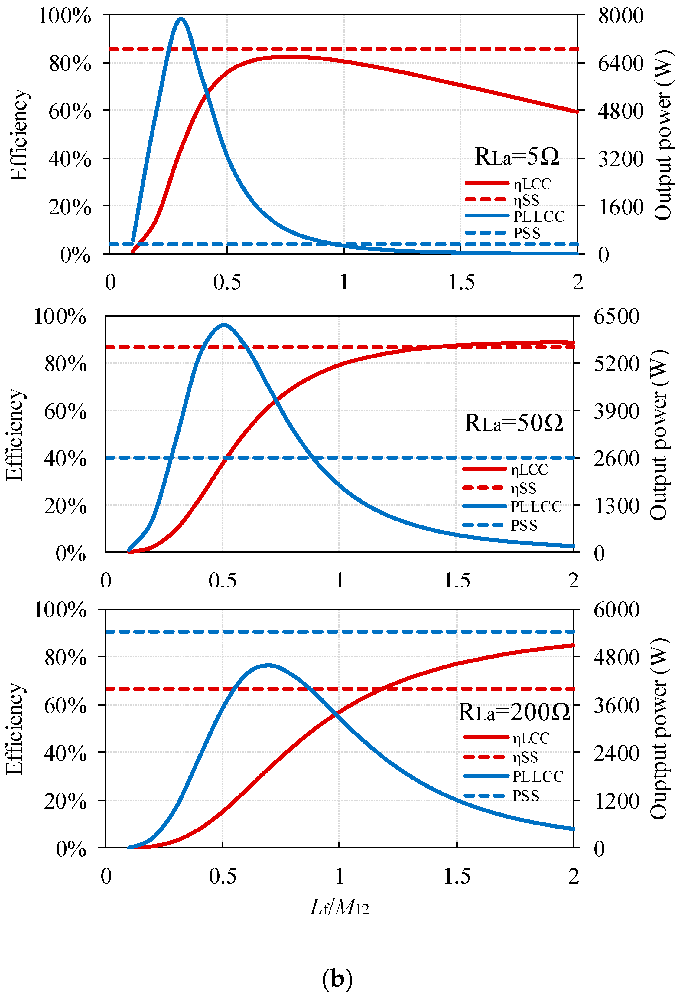
Figure 7.
Simulation results for the adjusted DC input voltage of the LCC-WPT system when : (a) Identical ESR of all the compensation components; (b) Identical ESR of all the compensation capacitors and identical quality factor of the inductors used in the LCC-WPT system.
Figure 7.
Simulation results for the adjusted DC input voltage of the LCC-WPT system when : (a) Identical ESR of all the compensation components; (b) Identical ESR of all the compensation capacitors and identical quality factor of the inductors used in the LCC-WPT system.
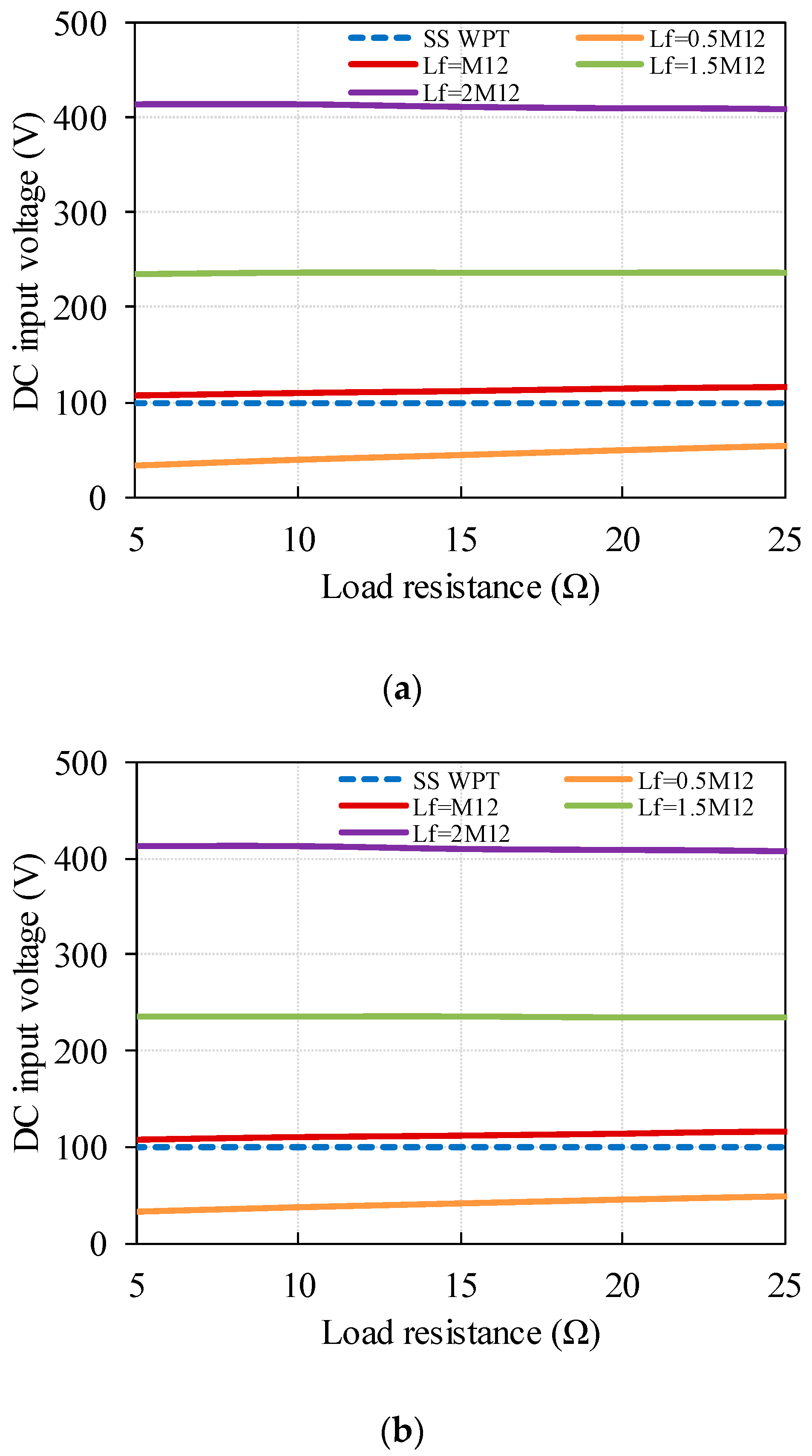
Figure 8.
Experimental platform of the WPT system.

Figure 9.
Flat spiral coils used in this work: (a) two coil schematic diagram; (b) practical coil.

Figure 10.
Air core inductance used as Lf.

Figure 11.
DC input voltage of the WPT systems when .

Figure 12.
Experimental results for output power of the WPT systems.

Figure 13.
System efficiency comparison of the SS and LCC WPT systems: (a) coil-to-coil efficiency; (b) system overall efficiency.
Figure 13.
System efficiency comparison of the SS and LCC WPT systems: (a) coil-to-coil efficiency; (b) system overall efficiency.
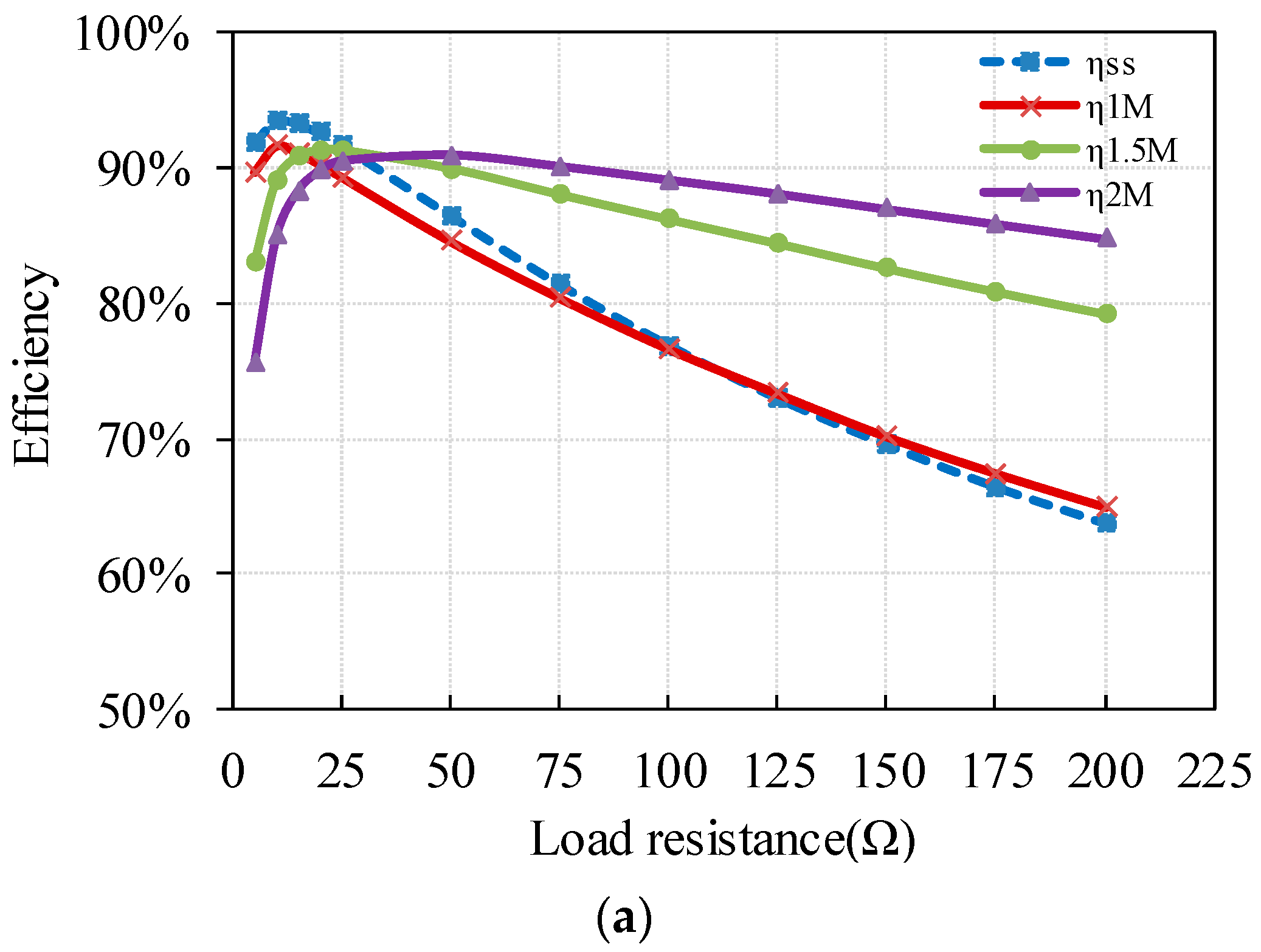
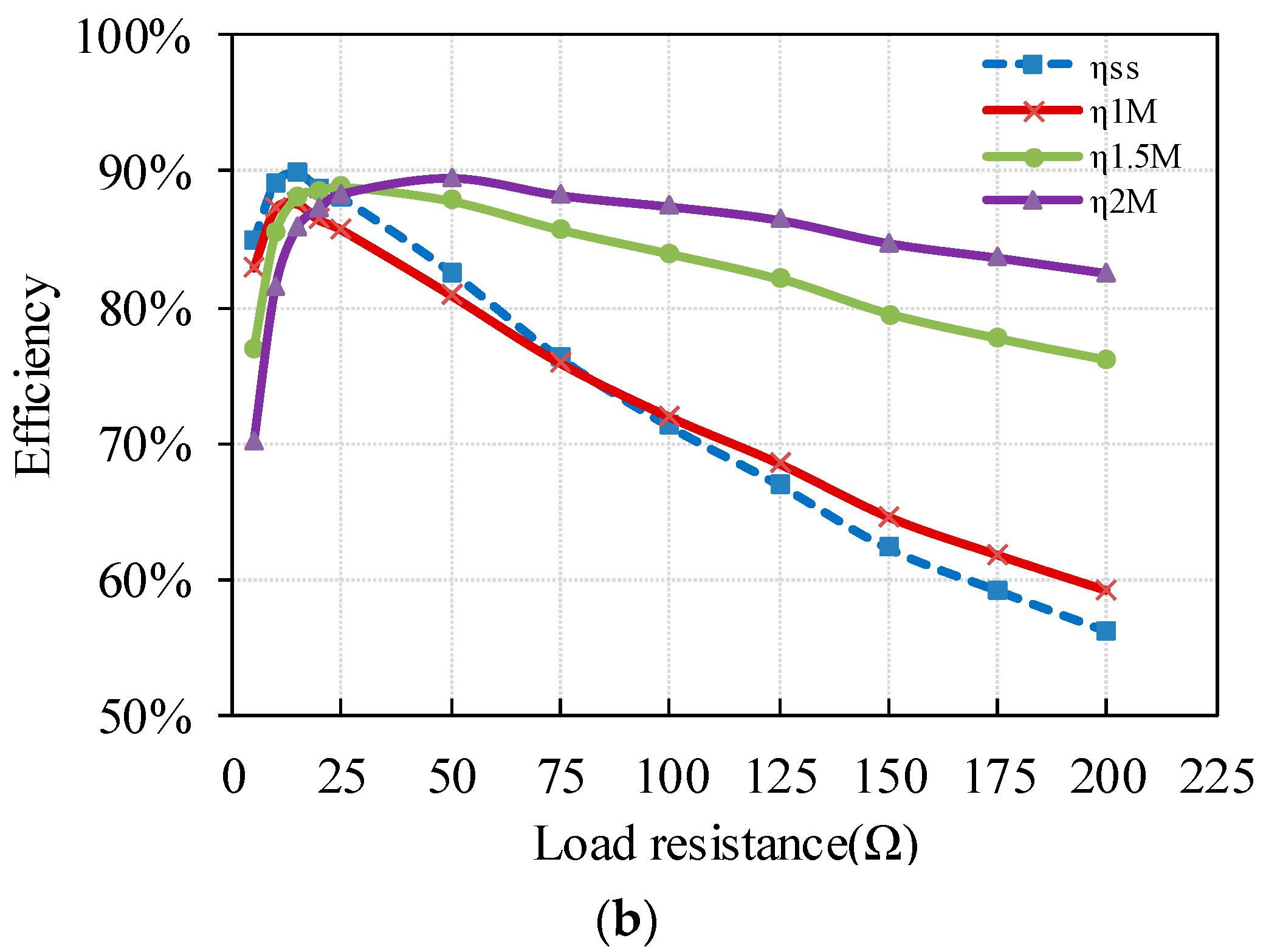
Figure 14.
Experimental voltage and current waveforms: (a) SS-WPT system; (b) LCC-WPT system.


Figure 15.
MOSFET losses in the WPT systems: (a) measured values; (b) radios the loss.

Figure 16.
Film capacitor rating voltage changing with frequency.
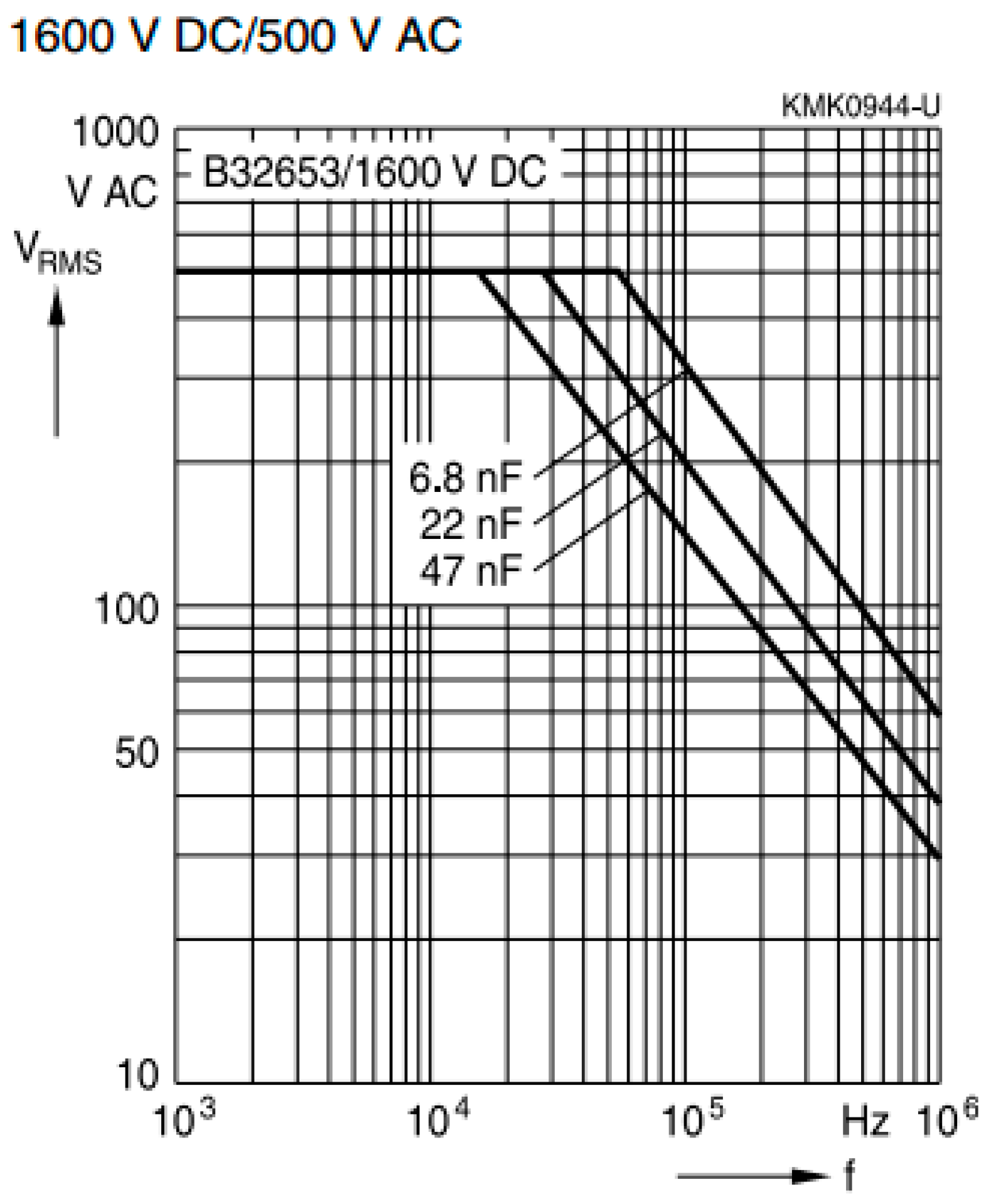
Figure 17.
Highest capacitor voltage in the systems: (a) measured values; (b) radios the voltage.
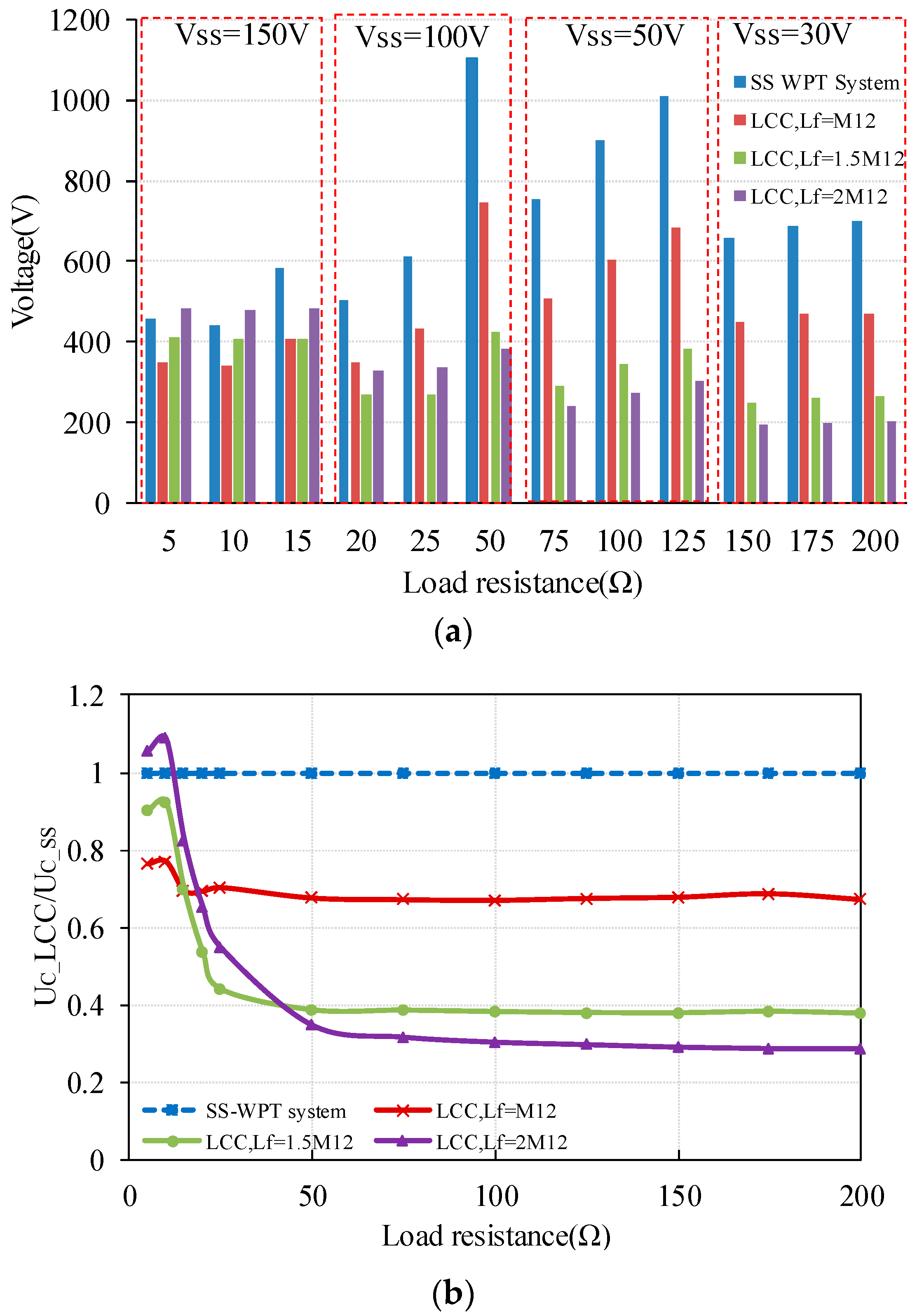
Figure 18.
Output power and system efficiency changing while misalignment occurs: (a) = 5 Ω; (b) = 25 Ω; (c) = 50 Ω.
Figure 18.
Output power and system efficiency changing while misalignment occurs: (a) = 5 Ω; (b) = 25 Ω; (c) = 50 Ω.


Figure 19.
(a) Variation in mutual inductance and Lf/M12 with misalignment; (b) Losses and efficiency comparison with 5 Ω load resistance when the coils are perfectly aligned.
Figure 19.
(a) Variation in mutual inductance and Lf/M12 with misalignment; (b) Losses and efficiency comparison with 5 Ω load resistance when the coils are perfectly aligned.

Table 1.
Calculation and simulation results when Lf = M12, VDC = 100 V, = 100 Ω.
| Lf = M12 | Ppri (W) | Psec (W) | ηLCC |
|---|---|---|---|
| Calculation results without parasitic resistance | 7119 | 7119 | 100% |
| Calculation results with expressions presented in [17] | 7119 | 7119 | 100% |
| Calculation results with parasitic resistance | 4699 | 3044 | 64.8% |
| Simulation results with parasitic resistance | 3494 | 2525 | 72.3% |
Table 2.
System parameters used in the calculation and simulation.
| Coil Parameters | Symbol | Value | Unit |
|---|---|---|---|
| DC input voltage | VDC | 100 | V |
| Coil resistance | , | 140 | mΩ |
| Additional inductor resistance | , | 80 | mΩ |
| Additional capacitor resistance | , , , | 80 | mΩ |
| Coil-to-Coil vertical distance | d | 150 | mm |
| Self-inductance | L1, L2 | 66 | μH |
| Resonant frequency | fr | 85 | kHz |
| Coupling coefficient | k | 0.27 |
Table 3.
Simulation results when RL = 100 Ω.
| Parameters | SS | Lf = M12 | Lf = 1.5 M12 | Lf = 2 M12 |
|---|---|---|---|---|
| VDC (V) | 50 | 60 | 107 | 172 |
| PL (W) | 894.2 | 898.5 | 894.2 | 894.2 |
| If1 (A) | N/A | 26.84 | 12.29 | 7.11 |
| ICf1 (A) | N/A | 28.83 | 15.74 | 12.57 |
| I1 (A) | 28 | 4.728 | 6.294 | 7.98 |
| I2 (A) | 3.796 | 26.71 | 18.21 | 13.84 |
| ICf2 (A) | N/A | 28.58 | 20.2 | 15.88 |
| ILf2 (A) | N/A | 4.372 | 4.187 | 4.039 |
| PLoss_Lf1 (W) | 0 | 57.63 | 12.08 | 4.04 |
| PLoss_Cf1 (W) | 0 | 66.49 | 19.82 | 12.64 |
| PLoss_L1 (W) | 111.49 | 3.13 | 5.55 | 8.92 |
| PLoss_C1 (W) | 63.71 | 1.79 | 3.17 | 5.09 |
| PLoss_Lf2 (W) | 0 | 1.53 | 1.40 | 1.31 |
| PLoss_Cf2 (W) | 0 | 63.35 | 32.64 | 20.17 |
| PLoss_L2 (W) | 2.02 | 99.88 | 46.42 | 26.82 |
| PLoss_C2 (W) | 1.15 | 57.07 | 26.53 | 15.32 |
| Primary side total loss (W) | 175.2 | 129.04 | 40.62 | 30.69 |
| Secondary side total loss (W) | 3 | 224 | 107 | 64 |
| Coil system total loss (W) | 178.37 | 352.87 | 147.62 | 94.31 |
| Coil system efficiency (W) | 84% | 72% | 86% | 91% |
Table 4.
Coil structure parameters.
| Coil Parameters | Symbol | Value | Unit |
|---|---|---|---|
| Wire radius | w | 3 | mm |
| Inner radius of the coil | Rinner | 30 | mm |
| Outer radius of the coil | Router | 290 | mm |
| Chanel width of the adjacent wire | p | 10 | mm |
| Turns | N | 16 | - |
| Coil-to-Coil vertical distance | d | 150 | mm |
| Self-inductance | L1, L2 | 66 | μH |
| Coupling coefficient | k | 0.27 | - |
Table 5.
Basic SS-WPT system parameters.
| SS-WPT System Parameters | Symbol | Value | Unit |
|---|---|---|---|
| DC power supply voltage | VDC | 0–600 | V |
| Driving frequency | fd | 85 | kHz |
| Resonant frequency | fr | 85 | kHz |
| Primary/ Secondary compensation capacitor | C1, C2 | 53 | nF |
| Load resistance | 5–200 | Ω | |
| Design maximum output Power | Pmax | 3.3 | kW |
Table 6.
LCC compensation topology specifications.
| LCC Compensation Topology Parameters | Symbol | Value | Unit |
|---|---|---|---|
| = M12 | 18.3 | μH | |
| 192 | nF | ||
| Ca | 72.6 | nF | |
| = 1.5 M12 | 27 | μH | |
| 130 | nF | ||
| Cb | 88.5 | nF | |
| = 2 M12 | 35 | μH | |
| 100 | nF | ||
| Cc | 111 | nF |
© 2017 by the authors. Licensee MDPI, Basel, Switzerland. This article is an open access article distributed under the terms and conditions of the Creative Commons Attribution (CC BY) license (http://creativecommons.org/licenses/by/4.0/).
Share and Cite
MDPI and ACS Style
Liu, X.; Clare, L.; Yuan, X.; Wang, C.; Liu, J. A Design Method for Making an LCC Compensation Two-Coil Wireless Power Transfer System More Energy Efficient Than an SS Counterpart. Energies 2017, 10, 1346. https://doi.org/10.3390/en10091346
AMA Style
Liu X, Clare L, Yuan X, Wang C, Liu J. A Design Method for Making an LCC Compensation Two-Coil Wireless Power Transfer System More Energy Efficient Than an SS Counterpart. Energies. 2017; 10(9):1346. https://doi.org/10.3390/en10091346
Chicago/Turabian StyleLiu, Xu, Lindsay Clare, Xibo Yuan, Chonglin Wang, and Jianhua Liu. 2017. "A Design Method for Making an LCC Compensation Two-Coil Wireless Power Transfer System More Energy Efficient Than an SS Counterpart" Energies 10, no. 9: 1346. https://doi.org/10.3390/en10091346
Note that from the first issue of 2016, this journal uses article numbers instead of page numbers. See further details here.