
Studies on the Effect of Nano-Sized MgO in Magnesium-Ion Conducting Gel Polymer Electrolyte for Rechargeable Magnesium Batteries

1
Key Laboratory of Inorganic Nanomaterials of Hebei Province, College of Chemistry and Material Science, Hebei Advance Thin Films Laboratory, College of Physical Science and Information Engineering, National Demonstration Center for Experimental Chemistry Education, Hebei Normal University, Shijiazhuang 050024, China
2
Key Lab of Environment Friendly Chemistry and Application in Ministry of Education, College of Chemistry, Xiangtan University, Xiangtan 411105, China
*
Authors to whom correspondence should be addressed.
Energies 2017, 10(8), 1215; https://doi.org/10.3390/en10081215
Submission received: 11 July 2017
/
Revised: 9 August 2017
/
Accepted: 11 August 2017
/
Published: 16 August 2017
(This article belongs to the Section I: Energy Fundamentals and Conversion)
Abstract
:Magnesium-ion conducting gel polymer electrolytes (GPEs) with different contents of nano-sized MgO have been prepared and investigated by various electrical and electrochemical techniques. The Mg2+ ion conduction in GPEs was confirmed from cyclic voltammetry and impedance analysis. It was found that doping appropriate nano-sized MgO in the GPE can induce significant improvements in both the electrochemical and the mechanical properties of GPEs. The composite GPE with 7% MgO shows a high ionic conductivity of 4.6 × 10⁻³ S/cm with electrochemical stability up to 4.7 V versus Mg2+/Mg at room temperature. Furthermore, it is free-standing and flexible with high tensile strength (9.7 ± 0.1 MPa) and elongation at break (91.7 ± 0.2%), further ensuring their potential applications as GPEs for rechargeable Mg batteries.
1. Introduction
With the increasing demand for energy, people began to pursue advanced energy storage devices [1,2,3,4]. Considering the negligible danger and enhanced security, studies on rechargeable magnesium batteries are expected to have ample promise for development in the future [2,3,4,5,6]. However, rechargeable Mg batteries suffer from several serious limitations, e.g., metallic Mg/electrolyte incompatibility and lack of suitable Mg2+ ion-conducting electrolytes. It has been reported that the irreversible deposition/dissolution of the Mg electrode in its simple salts/non-aqueous aprotic solvents is caused by the formation of a dense passivation layer on the Mg surface, resulting from its reaction with the electrolyte [5,6,7,8,9,10]. So more and more researchers focus on developing solid-state Mg2+ ion-conducting electrolytes to achieve rechargeability [11,12,13]. Gel polymer electrolyte (GPE), which is an important part component of solid-state Mg-batteries, is an excellent substitute for liquid electrolyte. It has been widely studied due toits chemical and mechanical stability which makes it suitable for application in advanced energy storage devices, e.g., batteries, supercapacitors, and so on [14,15,16]. There are few reports on the Mg2+ ion-conducting GPEs [17,18,19].
For a good GPE, both the ionic conductivity and stability (electrochemical and mechanical stability) are important. There are many methods for preparing GPE to improve the ionic conductivity [18,19,20,21,22,23]. To prepare superior GPE, electrospinning technique is a particular and useful way [24,25,26]. In addition, the matrices are also critical for GPE. We have studied the performance of thermoplastic polyurethane (TPU)/poly (vinylidene fluoride) (PVdF) based GPEs in lithium batteries [22,26]. TPU with low crystallinity possesses high tensile strength and elasticity. With good mechanical and high anodic stability, PVdF has been adopted as a good matrix for PEs in lithium batteries. Due to the advantages of TPU/PVdF matrixes, the GPEs show excellent electrochemical and mechanical properties in lithium batteries.
In this paper, we choose TPU and PVdF as matrices to study the effect of nano-sized MgO in magnesium-ion conducting GPEs. The GPEs based on TPU/PVdF with different amounts of nano-sized MgO have been prepared by electrospinning technique. The properties of the GPEs are investigated by stress–strain test, impedance analysis, cyclic voltammetry, and so on. It is found that doping appropriate contents of nano-sized MgO into the GPEs can improve their properties efficiently. The composite GPE with 7% MgO shows the best comprehensive performance.
2. Results and Discussion
2.1. Morphology/Structure and Differential Scanning Calorimeter Analysis
The virgin morphology of the membranes is shown in Figure 1. A porous structure with interconnected multifibrous layers are found in the samples. The average fiber diameter (AFD) of the membrane without MgO is about ~1.51 μm. As shown in Figure 1b–d, after adding nano-MgO, the surface of the membrane becomes less smooth and the AFD of the membrane decrease. When the content of MgO is 7%, the AFD of the membrane is only about 0.61 μm. Due to the homogeneous dispersibility of nano-MgO, the morphology of the membrane with MgO (<7%) seems to be the same as that of pristine membrane. With the content of MgO increasing, the surface of the membrane becomes coarser due to a lower dispersion of the MgO nano-particles (Figures S1–S3). Though the membrane with 15% MgO (Figure S3) has a lowest AFD (~0.32 μm), the network of interlaid and tubular structure is in disarray. Without the finer structure, the electrolyte uptake will be lower [22,26]. This predicts the membrane with MgO 7% will have a higher ionic conductivity.
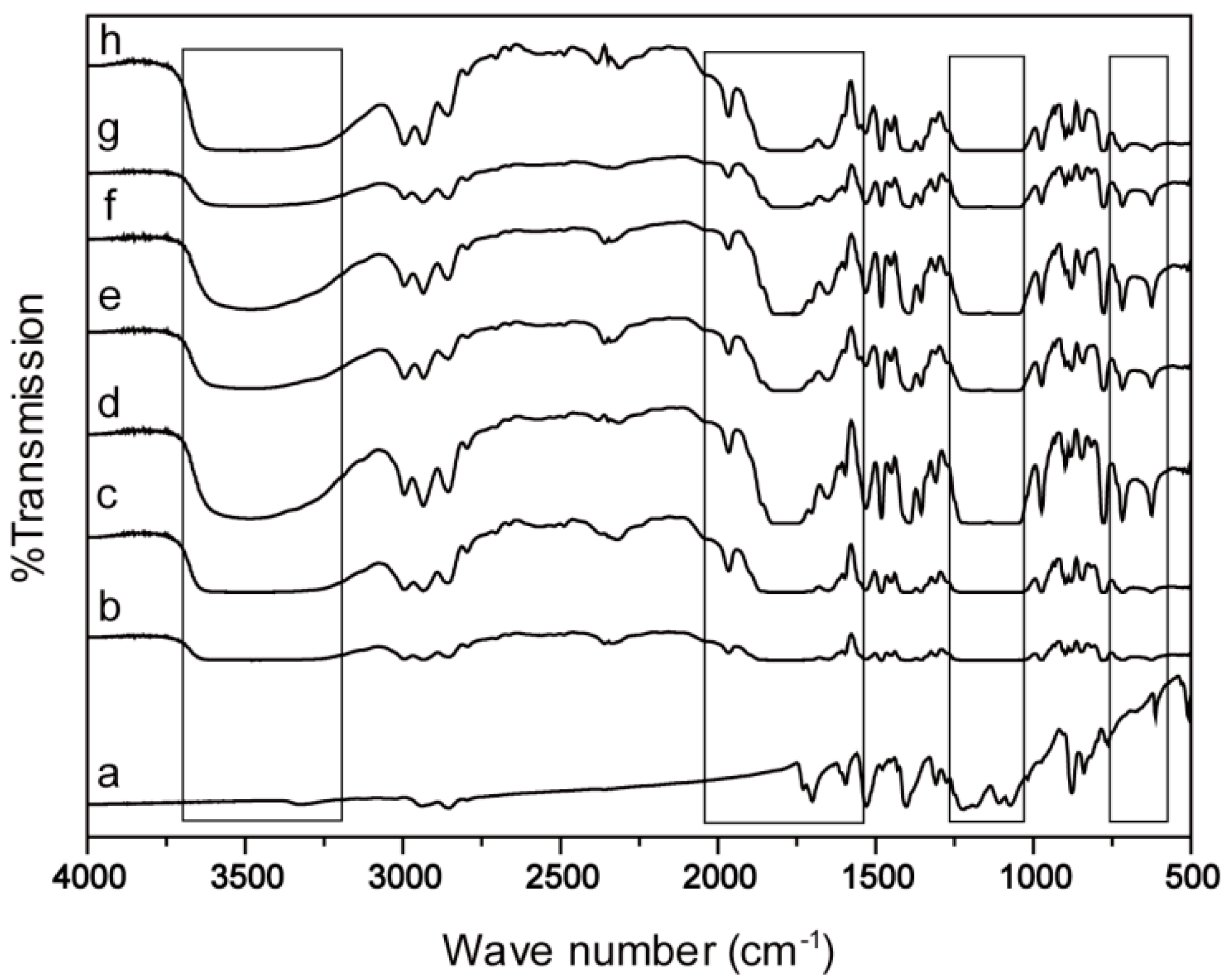
The Fourier transform infrared spectrometer (FTIR) spectra of the membranes with and without MgO are shown in Figure 2. The characteristic peaks which belong to TPU ( 3308 cm−1 and 1727 cm−1) and the peaks PVdF (1399 cm−1, 1073 cm−1 and 877 cm−1) are present clearly in the pristine eletrospun membrane (Figure 2a). When the membranes turn to GPEs (Figure 2b–h), the vibration peaks of amino-group (–NH) around 3600–3200 cm−1 and 1750–1650 cm−1 shift to higher band due to the formation of the more new freedom –N–H forms and the reduction of the hydrogen bonds within the hard domain. Moreover, with the formation of the interactions between Mg2+ and ether groups, the broad peak at around 1250–1110 cm−1 increases. With the addition of nano-MgO, the intensity of the peaks for ClO4− (650–600 cm−1) become strong and wider. The change of the peak intensity reveals more active ClO4− dissociates from Mg(ClO4)2 (Figure 2c–h). This implies the addition of nano-MgO promotes the dissociation of Mg(ClO4)2 in the GPEs.
Figure 3 displays the differential scanning calorimeter (DSC) tests of the eletrospun membrane and the GPEs. As shown in Figure 3, the melting temperature of the samples with nano-MgO is slightly lower than the without ones. The melting enthalpy (ΔHf) of the membrane with nano-MgO is much lower. As shown in Table S1, the ΔHf of the membrane with nano-MgO ranges from 7.52 J/g to 18.07 J/g. However the value of the ΔHf of the without one is 22.86 J g−1. The crystallinity values are calculated by Equation (1) and the results are shown in Table S1. The values of crystallinity decrease while the MgO contents increase. These changes might be due to the partial inhibition of the polymer crystallization by the addition of the nano-MgO [16,17,27]. Thus the amorphous regions in the polymer increases. The higher the amorphous of membrane is, the higher the conductivity enhancement is. The result implies that the GPE with 7% nano-MgO may have a high ionic conductivity.
2.2. Mechanical Properties and Porosity/Electrolyte Uptake
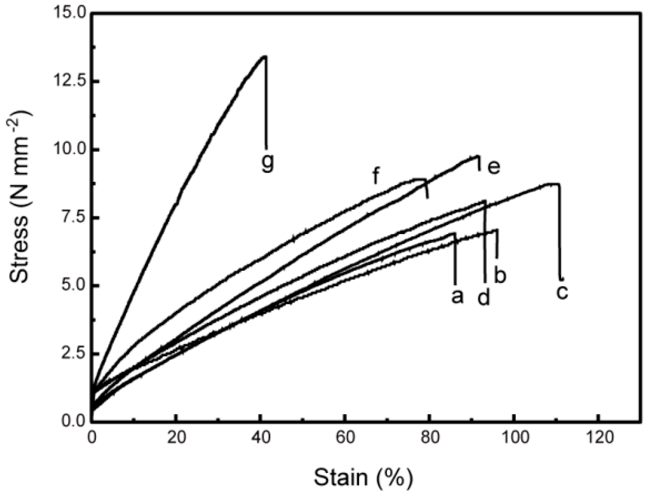
The mechanical property of the polymer membranes are shown in Figure 4. Both the mechanical tests and porosity of the membranes are given in Table S1. The results show that both the tensile strength and elongation at break performance of membranes can be improved by adding nano-MgO with appropriate contents. The membrane with 7% MgO shows the best mechanical property (high tensile strength (9.7 ± 0.1 MPa) with elongation at break (91.7 ± 0.2%)). These superior performances imply the sample with 7% MgO will be stable and flexible during charge/discharge processes and will subsequently be likely to be applied in polymer magnesium ion batteries.
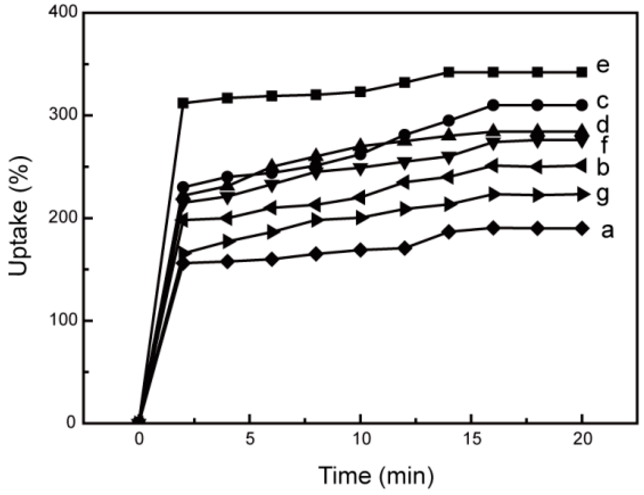
The porosity increases with the addition of nano-MgO due to the fine structures lapped by nanofibers. With the addition of nano-MgO, the AFDs of the membrane decrease. Then more gaps form in the sample. Thus the membrane with more gaps has a higher porosity. Though the membranes with a higher content of MgO (10% and 15%) have lower AFDs, their porosities are not the highest ones due to the huge gap created by the irregular interwoven structure of the nanofibers. Thus the sample with 7% MgO shows the highest porosity at 98%, implying a higher electrolyte uptake. As shown in Figure 5, the membranes with nano-MgO have a higher electrolyte uptake than those without, and the membrane with 7% MgO has the highest electrolyte uptake. These can be attributed to the high porosity and the high amorphous content of the polymer bases with nano-MgO. The liquid penetrates into the membrane very fast due to the unique interconnected pore structure. This is exactly the reason why the membrane with 7% MgO has the highest electrolyte uptake.
2.3. Ionic Conductivity
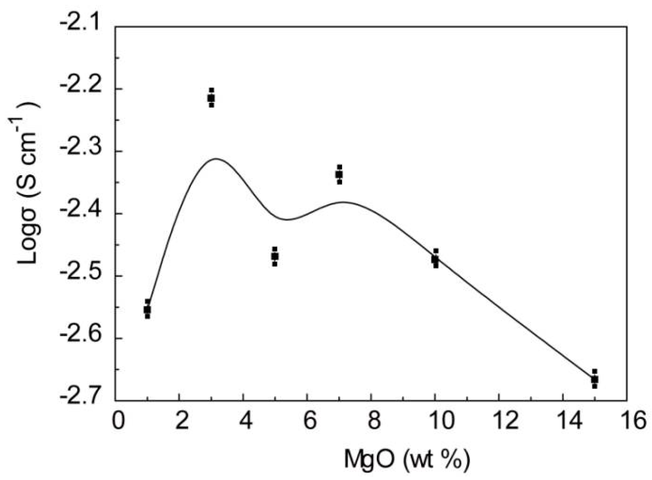
The conductivity of the GPEs with different MgO contents is shown in Figure 6 and Figure S4. Clearly an initial increase in the conductivity of GPEs by the addition of nano-MgO follows by two maxima which can be observed at 3% and 7 wt %. These behaviors have been reported by Pandey et al. [16,17]. The disaggregation of undissociated Mg(ClO4)2 into free ions with the addition of nano-MgO possibly gives rise to the first maximum of the conductivity. The second conductivity maximum is observed at 7 wt % MgO. This may explain the composite effect and the formation of the conducting interfacial space-charge double-layer between the nano-MgO with GPEs [16,17]. With the contents of nano-MgO increasing, too much nano-MgO hinders the motion of mobile ions. Thus, the conductivity declines after the second conductivity maximum [20]. The optimum conductivity value of the GPEs is 6.8 × 10⁻³ S/cm (GPE with 3 wt % MgO). The GPE with 7 wt % MgO, which has the best mechanical property, also has an excellent conductivity about 4.6 × 10⁻³ S/cm.
Figure 7 shows the changes of ionic conductivity of GPEs with temperature in the range 25–85 °C. The ionic conductivity of all the GPEs changes stable with the temperature increasing. This is due to the poor twists in the pore structure and the slow ion conduction in the swollen phase. To compare the differences of ionic transport behaviors between crystalline and amorphous phases, the σ values are fitted by the Arrhenius formula, respectively: σ = σ0exp (−Ea/RT) (Ea is activation energy, R is the gas constant, σ0 is the pre-exponential index and T is the testing absolute temperature). As shown in Figure 7, all the curves follow the Arrhenius equation. When the temperature is low, the GPEs are in high degree of crystallization. Thus the ionic conduction needs large activation energies. Therefore, the ionic conductivities for all the GPEs are very low. When the temperature increases, the GPEs become amorphous. Thus the activation energies for ionic conduction become lower, and the ionic conductivities are higher. From the ionic conductivity depending temperature tests, it was found that the GPE with 3 wt % MgO has remarkable conductivity about 4.6 × 10⁻³ S/cm at 25 °C and 7.5 × 10⁻³ S/cm at 85 °C. In addition, even at high temperatures, the GPEs are flexible and still self-standing, showing great potential applications in Mg ion batteries during a wider range of temperatures.
2.4. Electrochemical Activity and Stability
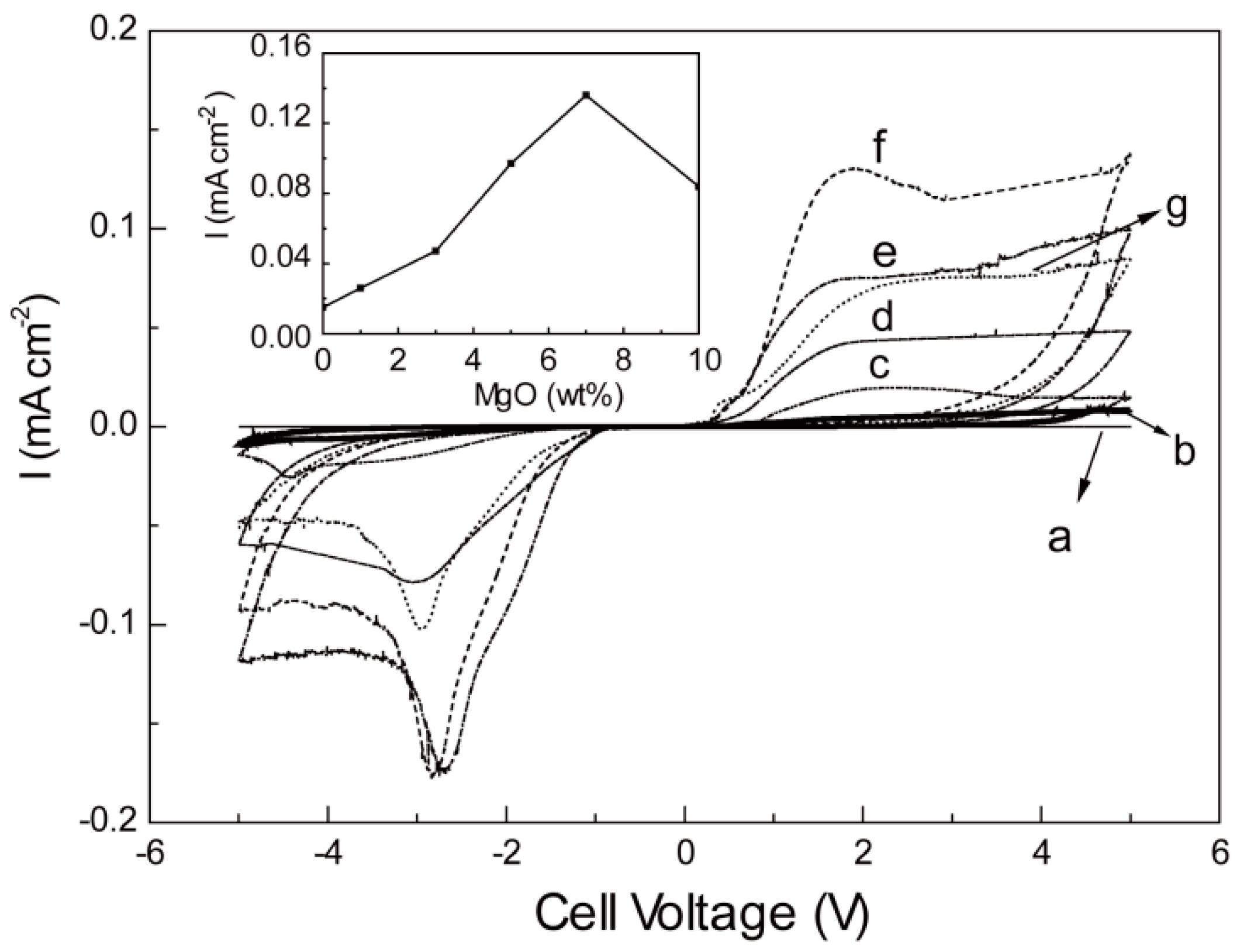
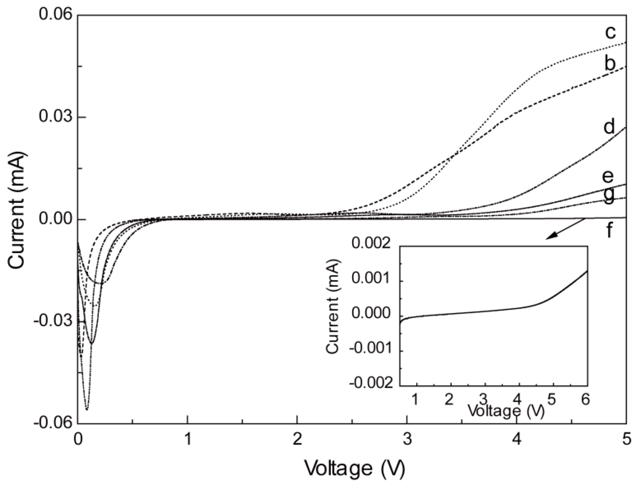
Cyclic voltammetry (CV) tests with Mg/GPE/Mg cells were carried out to check the Mg2+ ion conduction in the GPEs. We also test the cell with symmetrical SS electrodes for comparison. There is no current peak in the cell with SS electrodes. However, in cells with Mg electrodes, the current peaks are distinctly observed when the applied voltage is more than 2 V. This reveals the deposition and resolution of Mg2+ ion occurs at the Mg/GPE interface. It is noteworthy that Mg deposition occurs when the voltage is more than 2 V, perhaps due to the collapse of the dense passivation layer on the surface of metal Mg. Though Mg deposition occurs, the current peak of the GPE without MgO is unobvious. With the addition of nano-MgO, the separated value of the cathodic/anodic peak potentials decrease and the anodic/cathodic peak currents increase. Electrochemical activity enhancement may be attributed to the highly Mg2+ transmission paths along the interfaces formed between metal Mg and gel electrolyte with nano-MgO and the removal of impurities such as water from the interface by the nano-MgO [16,17,27]. When the GPE covers the surface of the Mg, the nanosized MgO dispersing in the polymer matrix locates on the Mg–gel electrolyte interface. Then MgO: Mg2+ species form space-charge regions and local electric fields. The enhanced Mg2+ electrochemical activity is probably attributed to the formation of the local electric field. In addition, the nanosized particles have a relatively large specific surface area, leading to the establishment of coherent conductive paths at the metal Mg/GPE interface. The newly-built paths, so-called “nano-bridges”, not only provide convenience for easy passing of Mg2+, but they also hinder impurities from reacting with metal Mg. Thus, metal Mg becomes to be electrochemical reversible under certain condition of relatively wide applied voltages. A peak current maximum appears with the addition of 7 wt % nano-MgO in the GPEs, as shown in Figure 8 (inset). This suggests that nano-MgO enhances the electrochemical activity at the Mg–gel electrolyte interface at room temperature.
The electrochemical stability tests of the GPEs are shown in Figure 9. In the high voltage range, electrodes/electrolytes begin to decompose resulting in the onset of current flow. So the upper limit of the electrolyte stability is within this voltage range. With the addition of the nano-MgO, the stability of the GPEs is further enhanced. The stable electrochemical window of the GPE with 7 wt % MgO is more than 4.7 V (versus Mg2+/Mg). The result implies that the addition of nano-MgO into GPE can increase both the electrochemical activity and electrochemical stablilty.
3. Materials and Methods
The 9% solution of TPU-PVdF (1:1, w/w) in DMF/acetone (3:1, w/w) with MgO powder in different weight ratios (from 0 to 15 wt %) was ultrasonicated for about 0.5 h to ensure proper dispersion of filler particles and stirred thoroughly at room temperature until forming a homogeneous solution. Then the solutions were electrospun into fibers under 28.5 kV at room temperature. Then the films were put on the table overnight and dried under vacuum at 60 °C for 12 h. The electrospun films were ~100 μm. Finally, the dried membranes were dipped in 1 M Mg(ClO4)2–EC/PC electrolyte solutions for 1 h in a glove box filled with argon at room temperature.
Thermoplastic polyurethane (TPU, Yantaiwanhua, 1190A) and Poly (vinylidene fluoride) (PVdF, aldrich) were dried under vacuum at 80 °C for 24 h. Magnesium oxide (MgO nanopowder, 99+% metals basis) were obtained from Alfa Aesar (Ward Hill, Haverhill, MA, USA). Magnesium perchlorate (Mg(ClO4)2, anhydrous, Alfa Aesar, Ward Hill, Haverhill, MA, USA) and MgO powder were vacuum dried at 120 °C for 72 h. 1.0 M Liquid electrolyte was made by dissolving a certain quality of Mg(ClO4)2 in ethylene carbonate (EC, Shenzhen Capchem Technology Co. Ltd., Shenzhen, China)/propylene carbonate (PC, Shenzhen Capchem Technology Co. Ltd.) (1/1, v/v). N-Dimethylforamide (DMF) and acetone were analytical purity and used as received without further treatment.
Membrane Characterization
The morphology of films was examined by Scanning electron microscope (SEM, Hitachi S-3500N, Hitachi, Osaka, Japan). The structure was investigated by FTIR spectra (Spectrum One, PerkinElmer Instruments, Shanghai, China).
The thermal characterization of the prepared polymer networks was carried out by differential scanning calorimeter (DSC) with a heating and cooling rate of 20 °C min−1 on a DSC TA (DSC-7, Perkin-Elmer Co., Shanghai, China) instrument. Samples were run under a nitrogen atmosphere over a temperature range of −90–230 °C. The crystallinity () was calculated based on the following Equation (1) from the DSC curves:
where and represent the fusion enthalpy of blend membrane and PVdF with 100% crystallinity, respectively. The value of is 104.7 J/g. is the measuring weight fraction of PVdF.
The mechanical strength of the polymer gel electrolyte films was measured by universal testing machines (UTM, Instron Instruments, Chicago, IL, USA). The extension rate was kept at 10 mm/min. The dimensions of the sheet used were 2 cm × 5 cm × 100–150 μm (width × length × thickness).
The porosity was investigated by immersing the membranes into n-butanol for 1h and then calculated by using the following relation (Equation (2)):
where and are the mass of the wet and dry membrane, respectively, the density of n-butanol, and the volume of the dry membrane.
The electrolyte uptake was determined by measuring the weight increase and calculated according to the following equation:
where W0 is the weight of dried films and W is the weight of swelled films.
The ionic conductivity of the composite film was measured with SS/PE/SS bl °C king cell by AC impedance measurement using an Autolab PGSTAT302N with a frequency range of 0.1–1 MHz. The thin films were prepared about 100 μm in thickness and 2.24 cm2 in area for impedance measurement. Thus, the ionic conductivity could be calculated from the following equation:
where σ is the ionic conductivity, Rb is the bulk resistance, h and S are the thickness and area of the films, respectively.
Electrochemical stability was measured by a linear sweep voltammetry (LSV) of an Mg/GPE/SS cell using an Autolab PGSTAT302N at a scan rate of 5 mV/s, with voltage from 0 to 5 V. Cyclic voltammetry (CV) was carried out using an Autolab PGSTAT302N at a scan rate of 0.1 mV/s in the potential range of −5–5 V (vs. Mg2+/Mg).
4. Conclusions
To summarize, TPU-PVdF based Mg2+ ion conducting GPEs with different amounts of nano-sized MgO have been prepared by electrospinning at room temperature. It can be observed that both of the electrochemical and the mechanical properties are improved with the addition of nano-sized MgO. The composite GPE with 7 wt % MgO displays the widest electrochemical stability and perfect mechanical stability. Also, its ionic conductivity is as high as 4.6 × 10⁻³ S/cm at room temperature. These results show that the incorporation of nano-sized MgO is an efficient way to improve the properties of GPEs.
Supplementary Materials
Supplementary materials can be found at www.mdpi.com/1996-1073/10/8/1215/s1.
Acknowledgments
This work was supported by the National Natural Science Foundation of China (Grant No. 21603055), the Natural Science Outstanding Youth Project Foundation of Hebei province (Grant No. B2017205149), the Hebei Provincial Common Colleges and Universities Program for Young Talents (Grant No. BJ2017042), and the National Postdoctoral Program for Innovative Talents (Grant No. BX201600047).
Author Contributions
Na Wu, Yu Wei and Taohai Li conceived and designed the experiments; Wei Wang performed the experiments; Na Wu and Wei Wang analyzed the data; Na Wu wrote the paper.
Conflicts of Interest
The authors declare no conflict of interest.
References
- Tarascon, J.M.; Armand, M. Issues and challenges facing rechargeable lithium batteries. Nature 2001, 414, 359–367. [Google Scholar] [CrossRef] [PubMed]
- Goodenough, J.B.; Kim, Y. Challenges for Rechargeable Li Batteries. Chem. Mater. 2010, 22, 587–603. [Google Scholar] [CrossRef]
- Pasta, M.; Wessells, C.D.; Huggins, R.A.; Cui, Y. A high-rate and long cycle life aqueous electrolyte battery for grid-scale energy storage. Nat. Commun. 2012, 3, 1149. [Google Scholar] [CrossRef] [PubMed]
- Zhang, T.; Zhou, H.S. A reversible long-life lithium-air battery in ambient air. Nat. Commun. 2013, 4, 1817. [Google Scholar] [CrossRef] [PubMed]
- Wu, N.; Lyu, Y.-C.; Xiao, R.-J.; Yu, X.-Q.; Yin, Y.-X.; Yang, X.-Q.; Li, H.; Gu, L.; Guo, Y.-G. A highly reversible, low strain Mg-ion insertion anode material for rechargeable Mg-ion batteries. NPG Asia Mater. 2014, 6, e120. [Google Scholar] [CrossRef]
- Wu, N.; Yin, Y.-X.; Guo, Y.-G. Improving the electrochemical properties of the red P anode in Na-ion batteries via the spaceconfinement of carbon nanopores. J. Mater. Chem. A 2015, 3, 24221–24225. [Google Scholar] [CrossRef]
- Liang, Y.; Feng, R.J.; Yang, S.Q.; Ma, H.; Liang, J.; Chen, J. Rechargeable Mg Batteries with Graphene-like MoS2 Cathode and Ultrasmall Mg Nanoparticle Anode. Adv. Mater. 2011, 23, 640–643. [Google Scholar] [CrossRef] [PubMed]
- NuLi, Y.; Yang, J.; Wang, J.; Li, Y. Electrochemical Intercalation of Mg2+ in Magnesium Manganese Silicate and Its Application as High-Energy Rechargeable Magnesium Battery Cathode. J. Phys. Chem. C. 2009, 113, 12594–12597. [Google Scholar] [CrossRef]
- Levi, E.; Gofer, Y.; Aurbach, D. On the Way to Rechargeable Mg Batteries: The Challenge of New Cathode Materials. Chem. Mater. 2010, 22, 860–868. [Google Scholar] [CrossRef]
- Chen, X.Z.; Li, H. Thermodynamic analysis on energy densities of batteries. Energy Environ. Sci. 2011, 4, 2614–2624. [Google Scholar]
- Tao, Z.L.; Xu, L.N.; Gou, X.L.; Chen, J.; Yuan, H.T. TiS2 nanotubes as the cathode materials of Mg-ion batteries. Chem. Commun. 2004, 18, 2080–2081. [Google Scholar] [CrossRef] [PubMed]
- Wu, N.; Yang, Z.Z.; Yao, H.R.; Yin, Y.X.; Gu, L.; Guo, Y.G. Improving the electrochemical performance of Li4Ti5O12 electrode in a rechargeable Mg battery by lithium-magnesium co-intercalation. Angew. Chem. Int. Ed. 2015, 54, 5757–5761. [Google Scholar] [CrossRef] [PubMed]
- Kim, J.; Lee, J.; You, J.; Park, M.-S.; Hossain, M.S.A.; Yamauchi, Y.; Kim, J.H. Conductive polymers for next-generation energy storage systems: Recent progress and new functions. Mater. Horiz. 2016, 3, 517–535. [Google Scholar] [CrossRef]
- Shin, W.-K.; Cho, J.; Kannan, A.; Lee, Y.-S.; Kim, D.-W. Cross-Linked Composite Gel Polymer Electrolyte using Mesoporous Methacrylate-Functionalized SiO2 Nanoparticles for Lithium-Ion Polymer Batteries. Sci. Rep. 2016, 6, 26332. [Google Scholar] [CrossRef] [PubMed]
- Stephan, A.M. Review on gel polymer electrolytes for lithium batteries. Eur. Polym. J. 2006, 42, 21–42. [Google Scholar] [CrossRef]
- Pandey, G.P.; Agrawal, R.C.; Hashmi, S.A. Performance studies on composite gel polymer electrolytes for rechargeable magnesium battery application. J..Phys. Chem. Solids 2011, 72, 1408–1413. [Google Scholar] [CrossRef]
- Pandey, G.P.; Agrawal, R.C.; Hashmi, S.A. Magnesium ion-conducting gel polymer electrolytes dispersed with nanosized magnesium oxide. J. Power Sources 2009, 190, 563–572. [Google Scholar] [CrossRef]
- Kumar, G.G.; Munichandraiah, N. Solid-state rechargeable magnesium cell with poly (vinylidenefluoride)-magnesium triflate gel polymer electrolyte. J. Power Sources 2001, 102, 46–54. [Google Scholar] [CrossRef]
- Yoshimoto, N.; Yakushiji, S.; Ishikawa, M. Rechargeable magnesium batteries with polymeric gel electrolytes containing magnesium salts. Electrochim. Acta 2003, 48, 2317–2322. [Google Scholar] [CrossRef]
- Oh, J.S.; Ko, J.M.; Kim, D.W. Preparation and characterization of gel polymer electrolytes for solid state magnesium batteries. Electrochim. Acta 2004, 50, 903–906. [Google Scholar] [CrossRef]
- Wu, X.-L.; Li, Y.-H.; Wu, N.; Xin, S.; Kim, J.-H.; Yan, Y.; Lee, J.-S.; Guo, Y.-G. Enhanced working temperature of PEO-based polymer electrolyte via porous PTFE film as an efficient heat resister. Solid State Ion. 2013, 245–246, 1–7. [Google Scholar] [CrossRef]
- Wu, N.; Cao, Q.; Wang, X.Y.; Li, X.Y.; Deng, H.Y. A novel high-performance gel polymer electrolyte membrane basing on electrospinning technique for lithium rechargeable batteries. J. Power Sources 2011, 196, 8638–8643. [Google Scholar] [CrossRef]
- Jeong, G.; Kim, J.-G.; Park, M.-S. Core–shell structured silicon nanoparticles@TiO2-x/carbon mesoporous microfiber composite as a safe and high-performance lithium-ion battery anode. ACS Nano 2014, 8, 2977–2985. [Google Scholar] [CrossRef] [PubMed]
- Hwang, S.M.; Lim, Y.-G.; Kim, J.-G.; Heo, Y.-U.; Lim, J.H.; Yamauchi, Y.; Park, M.-S.; Kim, Y.-J.; Dou, S.X.; Kim, J.H. A case study on fibrous porous SnO2 anode for robust, high-capacity lithium-ion batteries. Nano Energy 2014, 10, 53–62. [Google Scholar] [CrossRef]
- Hwang, S.M.; Kim, S.Y.; Kim, J.-G.; Kim, K.J.; Lee, J.-W.; Park, M.-S.; Kim, Y.-J.; Shahabuddin, M.; Yamauchi, Y.; Kim, J.H. Electrospun manganese–cobalt oxide hollow nanofibres synthesized via combustion reactions and their lithium storage performance. Nanoscale 2015, 7, 8351–8355. [Google Scholar] [CrossRef] [PubMed]
- Wu, N.; Cao, Q.; Wang, X.Y.; Li, S.; Li, X.Y.; Deng, H.Y. In situ ceramic fillers of electrospun thermoplastic polyurethane/poly(vinylidene fluoride) based gel polymer electrolytes for Li-ion batteries. J. Power Sources 2011, 196, 9751–9756. [Google Scholar] [CrossRef]
- Kim, J.R.; Choi, S.W.; Jo, S.M.; Lee, W.S.; Kim, B.C. Electrospun PVdF-based fibrous polymer electrolytes for lithium ion polymer batteries. Electrochim. Acta 2004, 50, 69–75. [Google Scholar] [CrossRef]
Figure 1.
The scanning electronic microscopy (SEM) images of the membranes with nano-sized MgO: (a) 0 wt %; (b) 1 wt %; (c) 3 wt %; and (d) 7 wt %.
Figure 1.
The scanning electronic microscopy (SEM) images of the membranes with nano-sized MgO: (a) 0 wt %; (b) 1 wt %; (c) 3 wt %; and (d) 7 wt %.
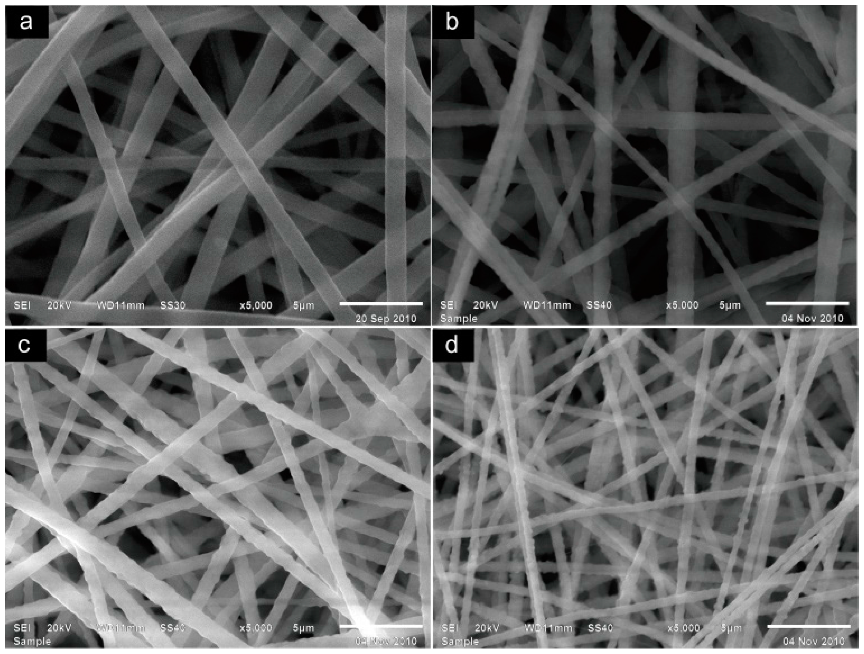
Figure 2.
The Fourier transform infrared spectrometer (FTIR) spectra of the samples: (a) the membranes without MgO fillers, (b–h) the gel polymer electrolytes (GPEs) with different content of nano-sized MgO; (b) 0%; (c) 1%; (d) 3%; (e) 5%; (f) 7%; (g) 10%; and (h) 15%.
Figure 2.
The Fourier transform infrared spectrometer (FTIR) spectra of the samples: (a) the membranes without MgO fillers, (b–h) the gel polymer electrolytes (GPEs) with different content of nano-sized MgO; (b) 0%; (c) 1%; (d) 3%; (e) 5%; (f) 7%; (g) 10%; and (h) 15%.

Figure 3.
The differential scanning calorimeter (DSC) curves of the membranes with different content of MgO. (b) 0%; (c) 1%; (d) 3%; (e) 5%; (f) 7%; and (g) 10%.
Figure 3.
The differential scanning calorimeter (DSC) curves of the membranes with different content of MgO. (b) 0%; (c) 1%; (d) 3%; (e) 5%; (f) 7%; and (g) 10%.
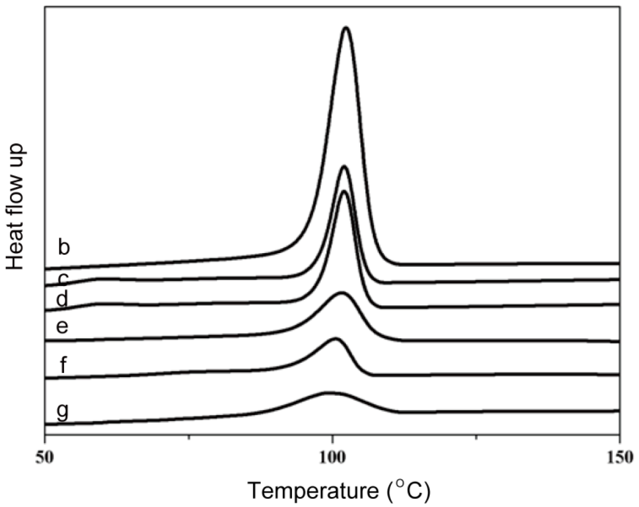
Figure 4.
The stress–strain curves of the films with different content of MgO: (a) 0 wt %; (b) 1 wt %; (c) 3 wt %; (d) 5 wt %; (e) 7 wt %; (f) 10 wt %; and (g) 15 wt %.
Figure 4.
The stress–strain curves of the films with different content of MgO: (a) 0 wt %; (b) 1 wt %; (c) 3 wt %; (d) 5 wt %; (e) 7 wt %; (f) 10 wt %; and (g) 15 wt %.

Figure 5.
The uptake behavior of the membranes with different content of MgO: (a) 0 wt %; (b) 1 wt %; (c) 3 wt %; (d) 5 wt %; (e) 7 wt %; (f) 10 wt %; and (g) 15 wt %.
Figure 5.
The uptake behavior of the membranes with different content of MgO: (a) 0 wt %; (b) 1 wt %; (c) 3 wt %; (d) 5 wt %; (e) 7 wt %; (f) 10 wt %; and (g) 15 wt %.

Figure 6.
The variation of room-temperature conductivity of the GPEs with different contents of nano-MgO.
Figure 6.
The variation of room-temperature conductivity of the GPEs with different contents of nano-MgO.

Figure 7.
The variation of ionic conductivity with temperature of the GPEs with different contents of nano-MgO.
Figure 7.
The variation of ionic conductivity with temperature of the GPEs with different contents of nano-MgO.
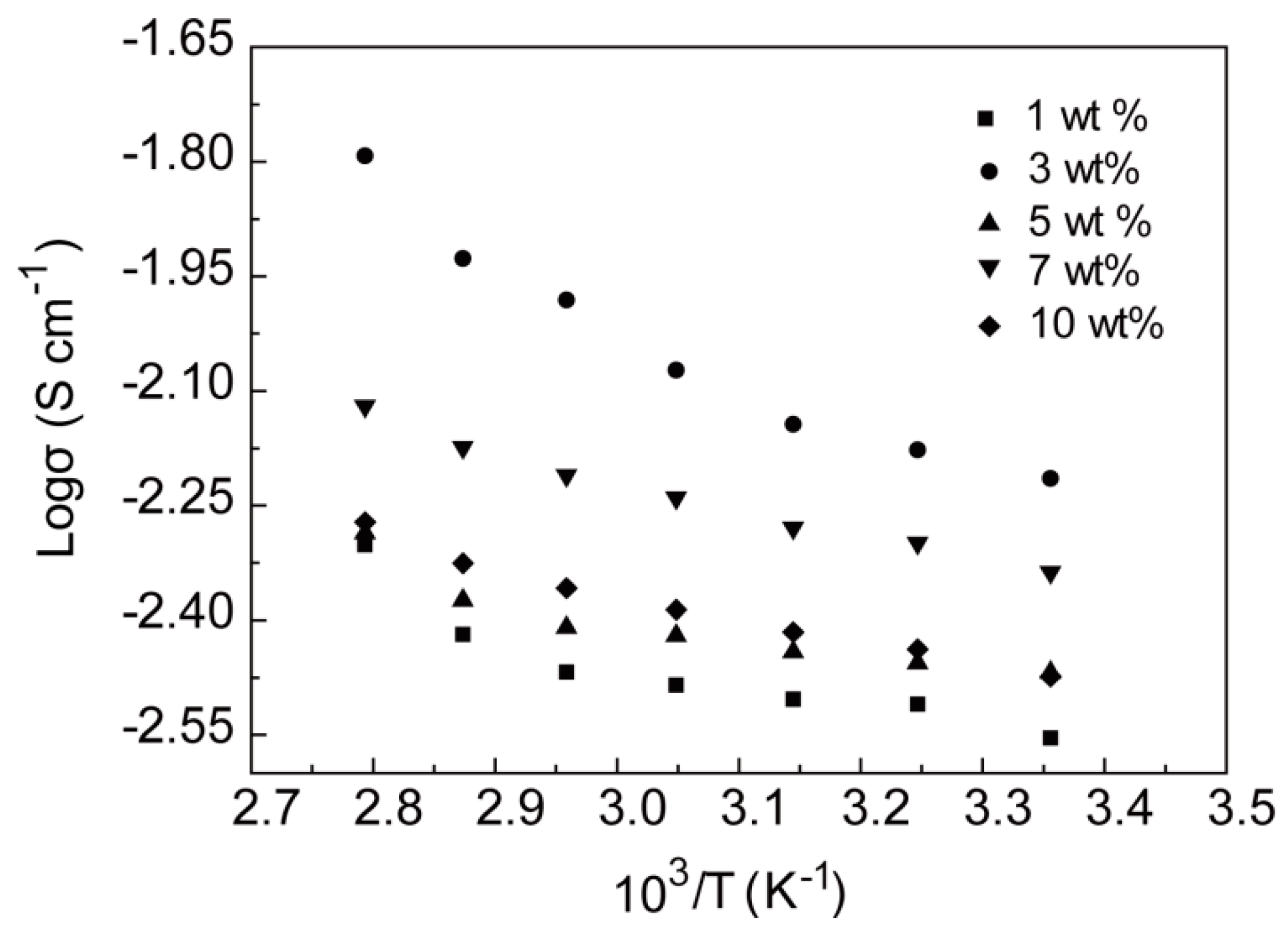
Figure 8.
Cyclicvoltammograms (CVs): (a) GPE with MgO 0 wt % in the SS/GPE/SS cell; (b–f) GPEs with different content of MgO in the Mg/GPE/Mg cell; (b) 0 wt %; (c) 1 wt %; (d) 3 wt %; (e) 5 wt %; (f) 7 wt %; and (g) 10 wt %.
Figure 8.
Cyclicvoltammograms (CVs): (a) GPE with MgO 0 wt % in the SS/GPE/SS cell; (b–f) GPEs with different content of MgO in the Mg/GPE/Mg cell; (b) 0 wt %; (c) 1 wt %; (d) 3 wt %; (e) 5 wt %; (f) 7 wt %; and (g) 10 wt %.

Figure 9.
Linear sweep voltammograms (LSVs) of the GPEs with different content of MgO: (b) 0 wt %; (c) 1 wt %; (d) 3 wt %; (e) 5 wt %; (f) 7 wt %; and (g) 10 wt %.
Figure 9.
Linear sweep voltammograms (LSVs) of the GPEs with different content of MgO: (b) 0 wt %; (c) 1 wt %; (d) 3 wt %; (e) 5 wt %; (f) 7 wt %; and (g) 10 wt %.
© 2017 by the authors. Licensee MDPI, Basel, Switzerland. This article is an open access article distributed under the terms and conditions of the Creative Commons Attribution (CC BY) license (http://creativecommons.org/licenses/by/4.0/).
Share and Cite
MDPI and ACS Style
Wu, N.; Wang, W.; Wei, Y.; Li, T. Studies on the Effect of Nano-Sized MgO in Magnesium-Ion Conducting Gel Polymer Electrolyte for Rechargeable Magnesium Batteries. Energies 2017, 10, 1215. https://doi.org/10.3390/en10081215
AMA Style
Wu N, Wang W, Wei Y, Li T. Studies on the Effect of Nano-Sized MgO in Magnesium-Ion Conducting Gel Polymer Electrolyte for Rechargeable Magnesium Batteries. Energies. 2017; 10(8):1215. https://doi.org/10.3390/en10081215
Chicago/Turabian StyleWu, Na, Wei Wang, Yu Wei, and Taohai Li. 2017. "Studies on the Effect of Nano-Sized MgO in Magnesium-Ion Conducting Gel Polymer Electrolyte for Rechargeable Magnesium Batteries" Energies 10, no. 8: 1215. https://doi.org/10.3390/en10081215
Note that from the first issue of 2016, this journal uses article numbers instead of page numbers. See further details here.