
Study on the Gas-Insulated Line Equivalent Model and Simplified Model


The Key Laboratory of Smart Grid of Ministry of Education, Tianjin University, Tianjin 300072, China
*
Author to whom correspondence should be addressed.
Energies 2017, 10(7), 901; https://doi.org/10.3390/en10070901
Submission received: 24 April 2017
/
Revised: 28 May 2017
/
Accepted: 27 June 2017
/
Published: 1 July 2017
Abstract
:The gas-insulated line (GIL) is one technical solution to allow the transmission of electricity underground at a high voltage level, yet its equivalent model is quite complicated. Based on an examination of the geometrical structure of the GIL and the way the metallic enclosure is grounded, this paper analyzed the electromagnetic and electrostatic coupling among the inner conductors and the metallic enclosures of the three phases. Then, the paper proposes a modeling method for the widely-used short-distance GIL based on the PI-model (the model consisting of two lumped admittance at each terminal and a lumped impedance in between). The GIL parameters were later simplified with the coupling effect of the metallic enclosure considered, and a simplified PI-model was produced. Finally, the proposed PI-model and its simplified version were built on the Power Systems Computer Aided Design (PSCAD) platform, and their effectiveness verified by simulation results.
1. Introduction
The Gas-insulated Line (GIL) is a transmission system for the transmission of electricity at a high voltage level, with SF6 or SF6-N2 gas mixture as the insulating medium and the conductor kept in the center of the metallic enclosure [1]. Particularly due to its high reliability, insulation-aging resistance, and little environmental impact, the GIL suitably serves as the connections between power plants and substations, and deals with complicated landscapes [2,3]. In real practice, the GIL is relatively short, only ranging from several hundred meters to 2 km in length when used as the connections within power plants. Even the longest GIL project—Sutong Ultra High Voltage GIL Pipe Gallery in China—stretches only 5.8 km. The complex structure of the GIL makes its electrical parameters different from those of the overhead line (OHL), and thus traditional models for transmission line simulation and calculation are no longer applicable to the GIL. Therefore, much study has been done on GIL modeling to prepare for the simulation of the electromagnetic transient process as well as operating/fault characteristics of the GIL.
Progress has been made in the study of parameter characteristics as well as GIL modeling: references [4,5] analyzed the magnetic field distribution among the conductors of the three phases in differing scenarios of GIL laying; reference [6] presents a numerical computation method for determining the magnetic field of the GIL; references [7,8,9,10] examined the electrical characteristics of underground conductors and the influence of the earth on conductor parameters, then proposed a method for solving the impedance matrix of underground conductors; references [11,12] studied the current and magnetic field distribution characteristics of the metallic enclosure and the inner conductor of a single-phase GIL, discussing how this distribution can change the electrical characteristics of the GIL; reference [13] presents results of numerical computation of electrical parameters of the flat and symmetrical three-phase GIL; reference [14,15] presents an analytical numerical method of determination of self and mutual impedances of GIL without taking into account skin and proximity effects as well as taking them into consideration; reference [16] presents a mathematical model of the GIL with taking into consideration skin and proximity effects; reference. [17] proposed a model of a three-phase GIL transmission system with the earth return current considered; reference [18] adopted the finite-element method in building a model of a three-phase GIL system; reference [19] proposed an approximate model based solely on the mutual inductance among the GIL inner conductor and the metallic enclosure; reference [20] suggested a modeling method for the simulation of a long-distance GIL system; and reference [21] adopted the lossless Bergeron model in building a model of a GIL–OHL hybrid transmission system. The magnetic field distribution and the electromagnetic coupling effect have been examined in these papers, and some models involving the electromagnetic coupling between the inner conductor and enclosure among phases are proposed.
For electromagnetic transient simulation of GILs in power systems, the GIL structure and the way of grounding are analyzed and an equivalent GIL PI-model is studied. To reduce the complexity and computation of the model, the equivalent parameters of the inner conductor are deduced and a simplified PI-model of the GIL is produced.
2. Geometrical Structure of the GIL and the Way the Enclosure Is Grounded
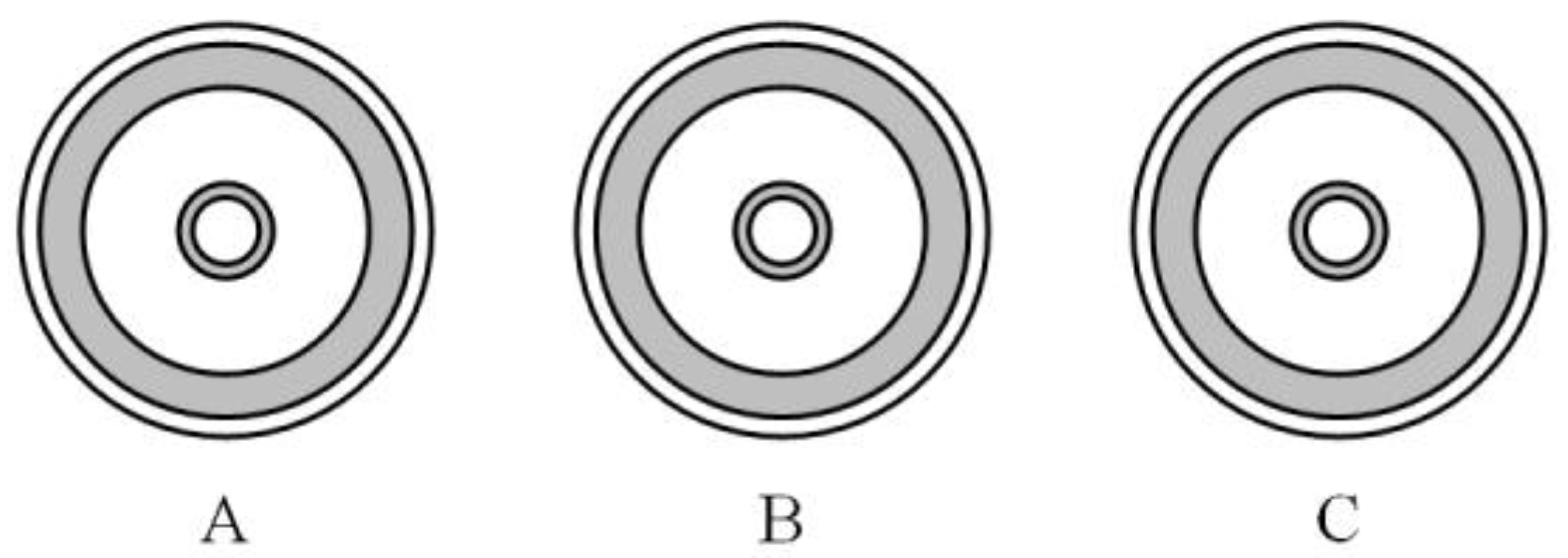
The typical structure of the GIL is shown in Figure 1: At the center lies the hollow (a design based on the skin effect) conductor made of an aluminum alloy of high electrical conductivity; the metallic enclosure is also made of an aluminum alloy, coated with an insulating material; and the conductor and enclosure are coaxial, with a SF6-N2 gas mixture filled in between.
The cross section of the GIL can be seen from Figure 1, from the inside to the outside being the conductor, the insulating gas mixture, the metallic enclosure, and the insulating coating. It is noted that the requirements of the insulation and gas-tightness become higher with increasing voltage level, as do the dimensions. The typical data of an 800 kV GIL are listed in Table 1.
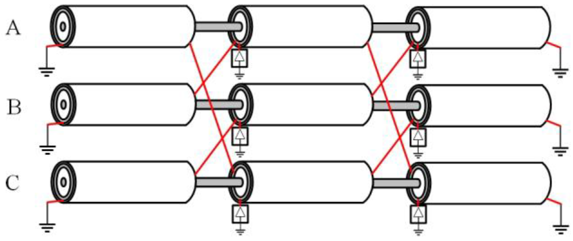
Different conditions require the GIL to be laid in different ways—above ground on structures, in a tunnel, or directly buried into the soil [22,23]. In any of these conditions, however, the metallic enclosure has to be grounded to achieve electromagnetic shielding of the conductor. Typically, there are two ways of grounding, namely, single-point grounding and cross-connection grounding [24], illustrated in Figure 2. The long-distance GIL usually adopts the latter to lower the induced voltage and current [24].
As for cross-connection grounding, the metallic enclosure of each phase is divided into identical segments, both ends of which are grounded; and each segment is then evenly divided into three small units, connected in the way as shown in Figure 2: the first units of phases A, B, and C are separately connected to the second units of phases C, A, and B, and the same pattern is for the connection between the second and third units. It is due to this arrangement that, in normal operation, the impact caused by the induced voltage on and induced current through the metallic enclosure of one phase offsets that of the other two. Arresters should be connected to both ends of each segment where the metallic enclosure should be insulated from the earth to prevent the impact of transient overvoltage [24].
3. Analysis of the Electrical Characteristics of the GIL
As the inner conductors and the metallic enclosures of the three phases are all conductive and have currents flowing through (induced current for the enclosure), there exist electromagnetic and electrostatic couplings between each pair. The case to be examined as an example is a GIL where the three phases are arranged in parallel (see Figure 3).
3.1. Electromagnetic Coupling
Take phase A as an example. The earth serves as the current return path for the inner conductor and the metallic enclosure, and its transmission equation is:
where ico and ien are respectively the currents flowing through the inner conductor and the metallic enclosure of phase i (i = A, B or C); ZEico and ZEien are respectively the per-unit length mutual impedances between the earth and the inner conductor as well as metallic enclosure of phase i; and E and ZEE are the earth current and the per-unit length impedance correspondingly. Since the earth is the reference point, the voltage of the earth E equals null. Thus:
The transmission equation of the conductor of phase A is:
And that of the metallic enclosure is:
By substituting (2) into (3) and (4), the electromagnetic coupling equations of the conductor and metallic enclosure are obtained as (5) and (6) separately:
The coupling equations of the rest two phases can be obtained in the same way.
3.2. Electrostatic Coupling
The insulating gas mixture and the insulating coating are the two layers each presenting voltage difference and thus electromagnetic coupling between their interior and exterior surfaces. Still take phase A as an instance. YA1 represents the per-unit length admittance of the insulating gas mixture, and YA2 represents that of the insulating coating. Thus, the leak current (from the inner conductor and the metallic enclosure) that changes as the GIL extends is expressed as:
It can be seen from (7) that the current variation in the conductor is due to the leak current from the conductor to the metallic enclosure through the insulating gas mixture, and that the current variation in the metallic enclosure is caused both by the leak current to the conductor as well as that to the surrounding environment.
(7) can be transformed to (8) to correspond to the conductor and the metallic enclosure:
So, the admittance matrix is:
The expressions of the electrostatic coupling can also be obtained for the other two phases in the same way.
Since the GIL is grounded either directly or via a medium, with the earth being the reference point, there is no electrostatic coupling among the metallic enclosures of the three phases, which means there is no admittance among them, either.
3.3. Impedance Matrix and Admittance Matrix
Vco and Ven are defined as the voltages on the inner conductor and the metallic enclosure respectively; correspondingly, Ico and Ien are the currents flowing through the two; Zco-co, Zen-en and Zco-en are the matrices of per-unit length conductor impedance, of the per-unit length metallic impedance and of the per-unit length mutual impedance between the conductor and the enclosure, respectively; and correspondingly, Yco-co, Yen-en, and Yco-en are the matrices of the per-unit length admittance.
Then, the analysis above leads to the following expressions:
where:
It can be seen from (10) and (11) that the impedance matrix is a 6 × 6 one with non-zero elements, while the admittance matrix is a 6 × 6 sparse matrix. They well reflect the electrical characteristics of the GIL.
4. GIL Equivalent Model Based on PI-Model
Electromagnetic simulation software like PSCAD has yet to upgrade to build models for GILs. One option is to use the OHL or cable system model to simulate the GIL, but this is only for GILs over 10 km, unsuitable in most cases, since GILs are relatively short. It is suggested in [25] that the gas-insulated bus below 300 m can be simulated by the lumped capacitor, while there will be unacceptable errors for the GIL beyond that length. With all factors considered, for GIL systems that usually range from several hundred meters to several kilometers, the PI-model is the most appropriate one.
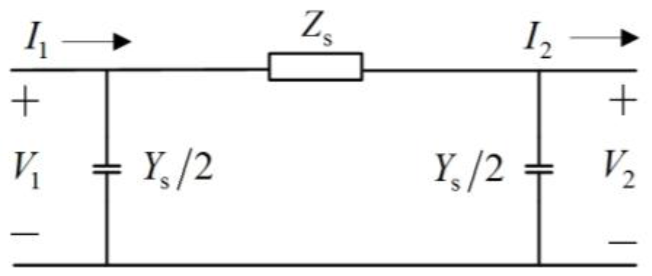
A single-phase PI-circuit is illustrated in Figure 4: Zs and Ys are the lumped impedance and lumped admittance, respectively; V1 and V2 are the two port voltages, and I1 and I2 are the corresponding currents.
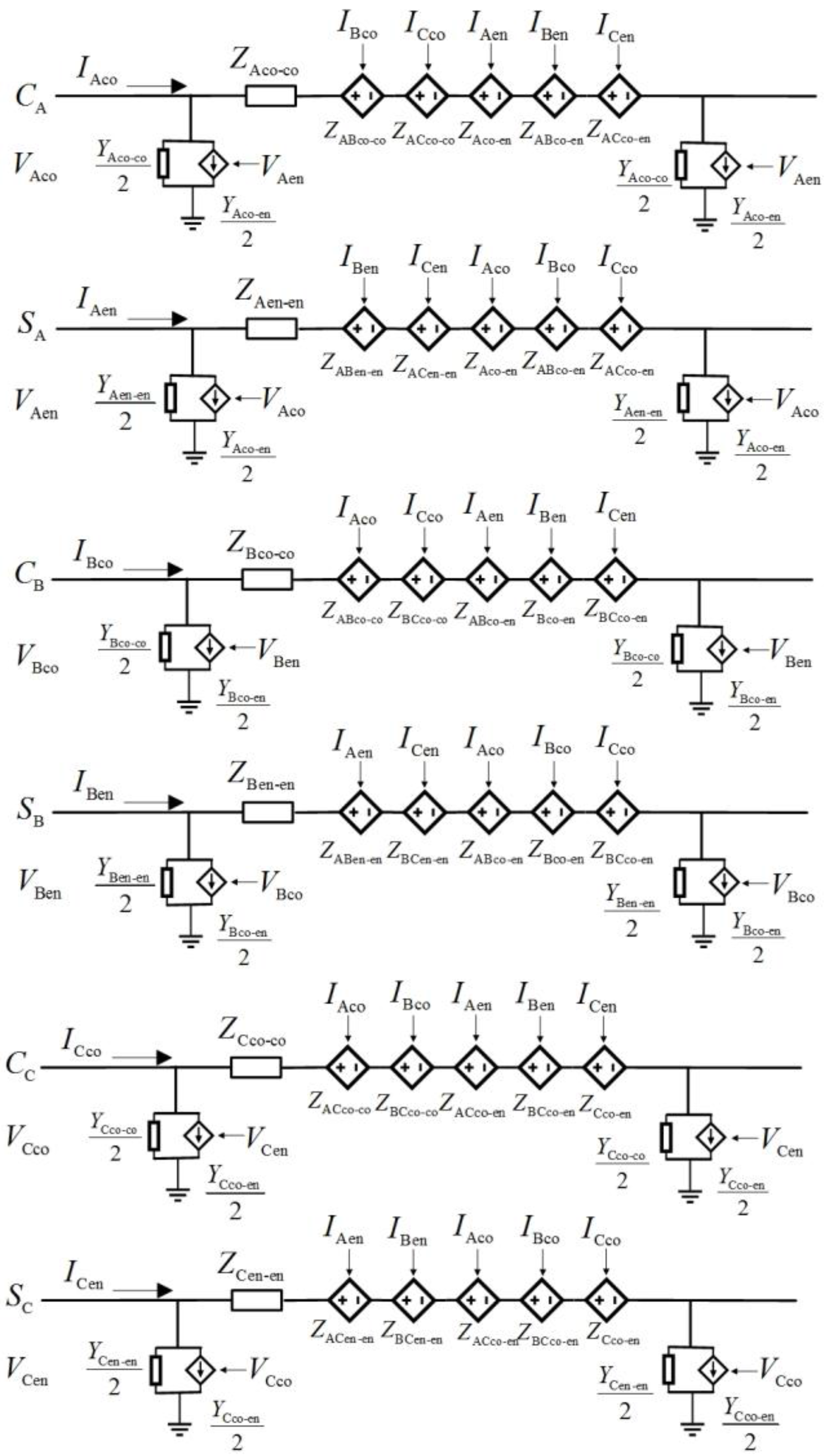
For the short-distance GIL system, the difference between V1 and V2 corresponds to the voltage change rate in (10), and the difference between I1 and I2 the current change rate in (11). Considering the electromagnetic and electrostatic coupling between the inner conductors and the metallic enclosures, a model of a three-phase GIL system involves 6 PI-circuits, and controlled voltage and current sources need to be introduced.
For each phase, the voltage drop along the inner conductor/metallic enclosure is composed of three parts:
- (1)
- The voltage drop along the impedance of the inner conductor/metallic enclosure, represented by the impedance in the PI-circuit.
- (2)
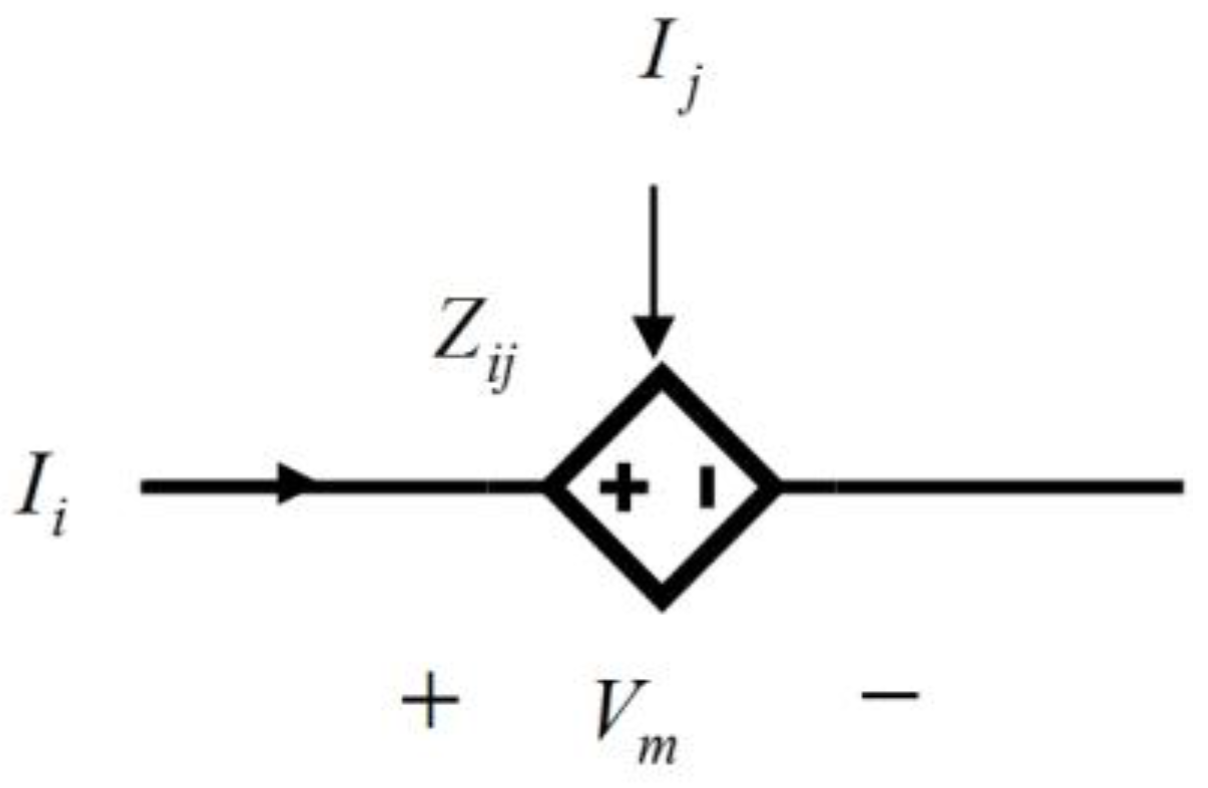
- The voltage drop along the inner conductor due to the electromagnetic coupling of the inner conductor currents of the other two phases and that of the three-phase metallic enclosure currents, can be simulated by the current-controlled voltage source shown in Figure 5.
- (3)
- The voltage drop along the metallic enclosure caused by the electromagnetic coupling of the metallic enclosure currents of the other two phases and that of the three-phase inner conductor currents, can also be simulated by the current-controlled voltage source shown in Figure 5.
It is noted that, in Figure 5, Zij is the mutual impedance between phase i and phase j, serving as the control coefficient.
For each phase, the current difference along the inner conductor/metallic enclosure is contributed to by:
- (1)
- The leak current to the earth, represented by the phase-to-ground admittance in the PI-circuit.
- (2)
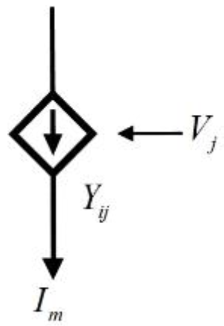
- The leak currents from both the inner conductor and metallic enclosure due to the admittance between the two, which can be simulated by the admittance between two transmission lines or the voltage-controlled current source shown in Figure 6.
Similarly, in Figure 6, Yij is the mutual admittance between phase i and phase j, serving as the control coefficient.
The PI-model of the GIL is shown as Figure 7.
It is noted that the model only describes a small unit of the GIL without enclosure cross-connection. In real practice, however, due to cross-connection grounding mentioned above, an equivalent GIL model contains three models like this connected accordingly (see Figure 2).
5. Parameter and Model Simplification
The model in Figure 7 is actually more than is needed for the electromagnetic transient analysis of the GIL, where only the electrical quantities at the two ends are required. Therefore, the model is supposed to be simplified and thus more efficient.
Considering the boundary constrains of the metallic enclosure, elements of the mutual inductance and mutual capacitance between the inner conductor and the metallic enclosure in the impedance and admittance matrices of the GIL can be eliminated, and obtained are the equivalent impedance and admittance matrices of the inner conductor still reflecting the influence of the metallic enclosure, as expressed by (17) and (18).
where Zeq-co is the matrix of the equivalent impedance of the inner conductor, and Yeq-co that of the equivalent admittance.
As only the electrical quantities of the inner conductor remain in (17) and (18), the influence of the metallic enclosure on the voltage and current of the inner conductor are represented by the equivalent impedance and admittance, respectively.
5.1. Analysis on the Equivalent Impedance Matrix of the Inner Conductor
The equivalent impedance matrix should be first found out by analyzing each of the three-unit metallic enclosures of a GIL segment in sequence, and simplifying the segment as a whole. The voltages at the head end and the tail end of unit i (i = 1, 2, or 3) are, respectively.
And the current through unit i is:
where H represents the head end of this unit, T represents the tail end of this unit.
Since the head end of the first unit and the tail end of the third unit are both grounded, there are
According to Figure 2, the metallic enclosures of the three phases A, B, and C of the first unit are connected with those of C, B, and A of the second unit separately, which is A with C, B with A, and C with B. Hence,
Similarly, for the second and third units, there is:
It is assumed that the three units are identical in length, which is l. Since l is very small, the voltage change rate on the metallic enclosure of each unit can be approximately represented by the ratio of the voltage drop between the two ends to l.
Now consider the three units as a whole and substitute (21)–(24) into (10). Obtained is:
where:
where:
By solving (25), the equivalent impedance matrix of the inner conductor is obtained as (28), with the electromagnetic coupling with the metallic enclosure considered.
5.2. Analysis on the Equivalent Admittance Matrix of the Inner Conductor
According to [24], no matter the way the GIL is laid, the induced voltage on the metallic enclosure is very low, and thus the metallic enclosure can be seen as the reference point, which means Ven in (11) is a null factor. By substituting the boundary constraints into (11), the equivalent admittance matrix of the inner conductor is obtained as:
which shows that the metallic enclosure has no impact on the admittance of the inner conductor.
5.3. GIL Simplified Model Based on PI-Model
A simplified PI-model can be built on the basis of (17) and (18), as illustrated by Figure 8: the impedance and admittance of each phase in the equivalent impedance matrix can be simulated by the impedance and admittance in the PI-circuit, respectively. The mutual impedance among phases by the current-controlled voltage source and the mutual admittance is null.
6. Simulation and Analysis
PSCAD-based simulations are carried out, and the results are compared against real data to verify the effectiveness of the proposed PI-model and its simplified version.
According to [26], for a voltage level of 1000 kV and insulating gas pressure of 0.5 Mpa, the spacing between the inner conductor and the metallic enclosure should be 192 mm to 215 mm, and the internal diameter of the metallic enclosure should be 661 to 684 mm. Detailed parameters are listed in Table 2.
And “ε0” is the permittivity of vacuum:
The cable model in PSCAD is adopted to build the model for the GIL. The three-phase GILs are arranged horizontally with the spacing between any two phases being 1.5 m (see Figure 3), buried at a depth of 0.5 m. Other parameters are set according to Table 2. The length of the GIL is 15 km, since PSCAD may produce errors in simulating a cable below that length.
After the simulation, the PSCAD produces a 6 × 6 per-unit length series impedance matrix (Z0) and a per-unit length shunt admittance matrix (Y0), which are the electrical parameters calculated from the GIL geometrical parameters. Z0 and Y0 can be transformed into the unit-length impedance and admittance matrix in (10) and (11) to correspond to the conductor and the metallic enclosure by the elementary row and column transformation. The impedance matrix and the admittance matrix of a transposition unit—that is, Z1 and Y1—are equal to the unit-length impedance and admittance matrix multiplied by the length of the unit, where the length of each unit is 500 m. Z1 and Y1 are described in Appendix A.
The GIL model is built according to that in Figure 7 and based on the connection method shown in Figure 2. Parameters are set in conformity to the matrices Z1 and Y1 above.
The GIL simplified model is built in PSCAD in the same way, and the impedance, admittance, and control coefficient in this model can be obtained from (28) and (29).
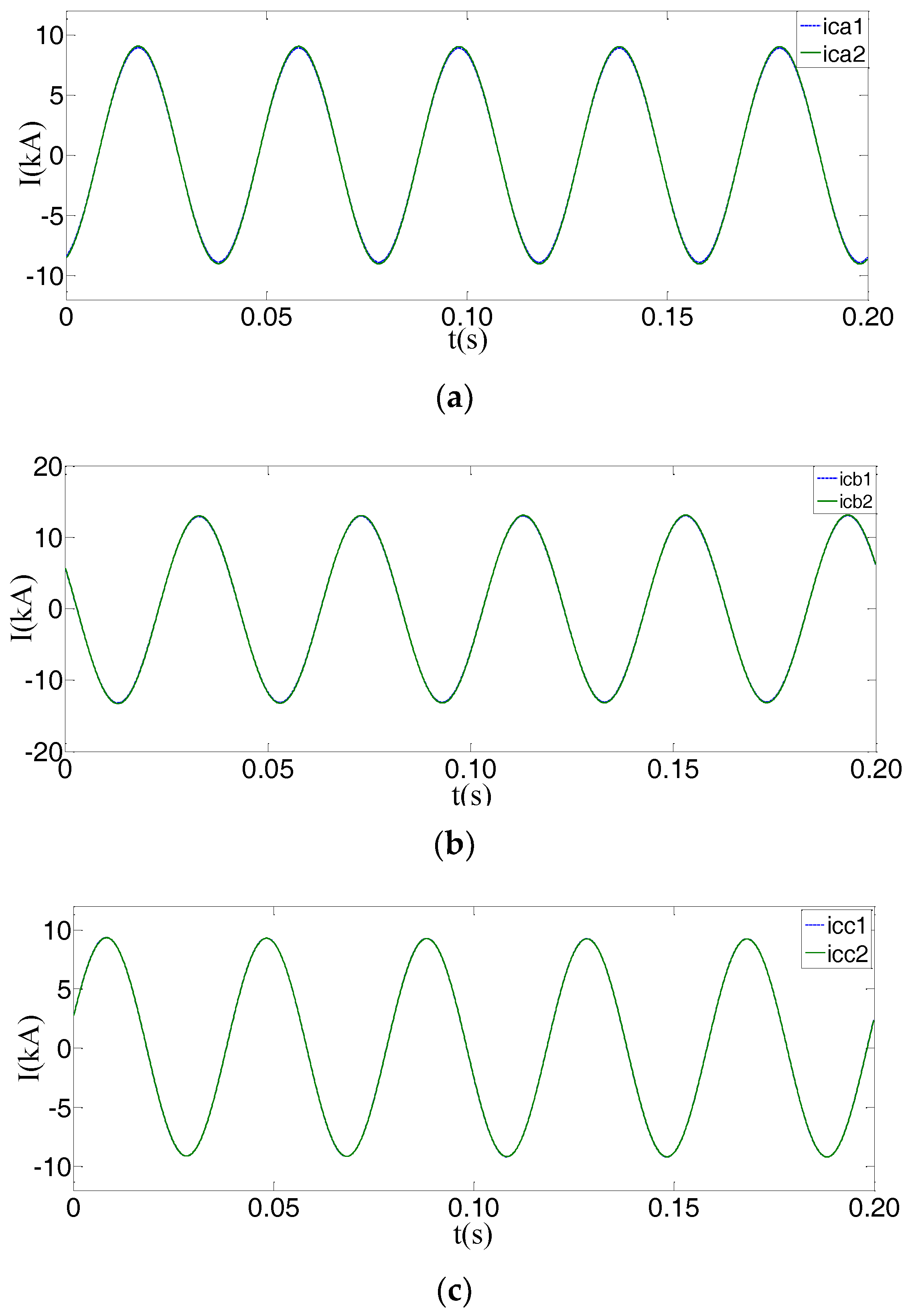
The same unbalanced voltage is added at both ends of the two models above, and the current of each phase is measured. The current of each phase of the two models are measured by the same oscilloscope. As shown in Figure 9, the blue curve represents the current in the PI-model, and the green one the simplified model.
It can be seen from Figure 9 that with the same unbalanced voltage, the current waveforms of the two models almost overlap completely, and their port electrical characteristics are identical. In this paper, the currents flowing through the two models at different voltage amplitudes and phase angles are measured. The typical results are shown in Table 3, Table 4 and Table 5.
In Table 3, Table 4 and Table 5 “current1” and “current2” are the currents flowing through the GIL equivalent and simplified model, respectively.
And “error” means:
where current1RMS and current2RMS are the corresponding root mean squares of current1 and current2.
7. Conclusions
This paper analyzed the electrical characteristics of the GIL based on an examination of the GIL structure and the way of grounding, and proposed an equivalent PI-model for the GIL. Furthermore, the paper presented the simplification process of the equivalent parameters of the inner conductor, retaining the electromagnetic and electrostatic couplings with the metallic enclosure as the factors. On this basis, the simplified PI-model of the GIL is produced. The main features and novelty are listed as follows:
- (1)
- The equivalent GIL PI-model proposed in the paper is based on the parameters and the coupling effects of the phase conductors and metallic enclosures, so it can demonstrate the electrical characteristics of all the conductor layers, and further serve as a basis for electromagnetic transient analysis for the GIL with short-circuiting, disconnection, etc.
- (2)
- According to the simulation results, the equivalent GIL PI-model and its simplified version show almost identical port electrical characteristics when the same voltage has been added at both ends of the two models. Thus, the simplified model can replace the equivalent GIL PI-model in the simulation process.
- (3)
- The structure and parameters of the simplified GIL PI-model is more concise than the equivalent GIL PI-model. Therefore, it could simplify the electromagnetic transient calculation of the power system that includes the GIL, which is mainly used for simulation where only the electrical quantities of the inner conductor are concerned.
Acknowledgments
This work was supported in part by the National Natural Science Foundation of China under Grant 51677125 and by the Science and Technology Project of the State Grid Corporation of China: Research of Relay Protection Technology for UHV GIL-overhead Hybrid Transmission Line.
Author Contributions
Botong Li put forward the research direction, organized the research activities, provided theory guidance, and completed the revision of the article. Tianfeng Gu completed the principle analysis and the method design, provided the results of the simulation, and drafted the article. Yunke Zhang examined the model and gave some advice. Valuable comments on the first draft were received from Bin Li and Botong Li. All four were involved in revising the paper.
Conflicts of Interest
The authors declare no conflict of interest.
Appendix A
The impedance matrix and admittancea matrix of the GIL generated by PSCAD:
References
- Qi, B.; Zhang, G.X.; Li, C.R.; Gao, C.J.; Zhang, B.Y.; Chen, Z.Z. Research status and prospect of gas-insulated metal enclosed transmission line. High Volt. Eng. 2015, 41, 1466–1473. [Google Scholar]
- Koch, H.; Hillers, T. Second-generation gas-insulated line. Power Eng. J. 2002, 16, 111–116. [Google Scholar] [CrossRef]
- Koch, H.; Hopkins, M. Overview of gas insulated lines (GIL). In Proceedings of the IEEE Power Engineering Society General Meeting, San Francisco, CA, USA, 12–16 June 2005. [Google Scholar]
- Benato, R.; Carlini, E.M.; Di-Mario, C.; Fellin, L.; Paolucci, A.; Turri, R. Gas insulated transmission lines in railway galleries. IEEE Trans. Power Deliv. 2005, 20, 704–709. [Google Scholar] [CrossRef]
- Benato, R.; Fellin, L. Magnetic field computation for gas insulated lines installed in gallery. In Proceedings of the 39th International Universities Power Engineering Conference (UPEC), Bristol, UK, 6–8 September 2004. [Google Scholar]
- Sarajcev, P. Numerical analysis of the magnetic field of high-current busducts and GIL systems. Energies 2011, 4, 2196–2211. [Google Scholar] [CrossRef]
- Tsiamitros, D.A.; Papagiannis, G.K.; Dokopoulos, P.S. Earth return impedances of conductor arrangements in multilayer soils—Part I: Theoretical model. IEEE Trans. Power Deliv. 2008, 23, 2392–2400. [Google Scholar] [CrossRef]
- Tsiamitros, D.A.; Christoforidis, G.C.; Papagiannis, G.K.; Labridis, D.P.; Dokopoulos, P.S. Earth conduction effects in systems of overhead and underground conductors in multilayered soils. IEE Proc. Gener. Transm. Distrib. 2006, 153, 291–299. [Google Scholar] [CrossRef]
- Benato, R.; Paolucci, A. Multiconductor cell analysis of skin effect in Milliken type cables. Electr. Power Syst. Res. 2012, 90, 99–106. [Google Scholar] [CrossRef]
- Benato, R.; Sessa, S.D.; Guglielmi, F.; Partal, E.; Tleis, N. Ground return current behaviour in high voltage alternating current insulated cables. Energies 2014, 7, 8116–8131. [Google Scholar] [CrossRef]
- Benato, R.; Di-Mario, C.; Koch, H. High-capability applications of long gas-insulated lines in structures. IEEE Trans. Power Deliv. 2007, 22, 619–626. [Google Scholar] [CrossRef]
- Metwally, I.A. Thermal and magnetic analyses of gas-insulated lines. Electr. Power Syst. Res. 2009, 79, 1255–1262. [Google Scholar] [CrossRef]
- Piatek, Z.; Kusiak, D.; Szczegielniak, T. Electromagnetic field and impedances of high current busducts. In Proceedings of the 2010 Proceedings of the International Symposium, Wroclaw, Poland, 20–22 September 2010. [Google Scholar]
- Piatek, Z. Self and mutual impedances of a finite length gas-insulated transmission line (GIL). Electr. Power Syst. Res. 2007, 77, 191–203. [Google Scholar] [CrossRef]
- Piatek, Z. Impedances of finite-length isolated phase busducts. Acta Tech. CSAV 2008, 53, 393–431. [Google Scholar]
- Sarajcev, P.; Martinac, I.; Radic, Z. Coupled electromagnetic and thermal analysis of single-phase insulated high-current busducts and GIL systems. Am. J. Electr. Electron. Eng. 2013, 1, 23–31. [Google Scholar] [CrossRef]
- Benato, R.; Dughiero, F.; Forzan, M.; Paolucci, A. Proximity effect and magnetic field calculation in GIL and in isolated phase bus ducts. IEEE Trans. Magn. 2002, 38, 781–784. [Google Scholar] [CrossRef]
- Benato, R.; Dughiero, F. Solution of coupled electromagnetic and thermal problems in gas insulated transmission lines. IEEE Trans. Magn. 2003, 39, 1741–1744. [Google Scholar] [CrossRef]
- Wang, Y.N.; Ding, W.D.; Gou, Y.; Xia, J.; Yan, J.Q.; Wang, J.S.; Li, Z.B. Discussion of the grounding method of gas insulated transmission line. High Volt. Appar. 2016, 52, 98–102. [Google Scholar]
- Elnaddab, K.; Haddad, H.; Griffiths, H. The transmission characteristics of gas insulated lines (GIL) over long distance. In Proceedings of the 47th International Universities Power Engineering Conference (UPEC), Uxbridge, UK, 4–7 September 2012. [Google Scholar]
- Goll, F.; Witzmann, R.; Neumann, C.; Imamovic, D. Modeling techniques for lightning overvoltage analysis using the example of gas insulated transmission lines (GIL). Proceeding of the IEEE 1st International Conference on Condition Assessment Techniques in Electrical Systems (IEEE CATCON), Kolkata, India, 6–8 December 2013. [Google Scholar]
- Koch, H. Basic information on gas insulated transmission lines (GIL). In Proceedings of the IEEE Power Engineering Society General Meeting, Pittsburgh, PA, USA, 20–24 June 2008. [Google Scholar]
- Siemens. Gas-Insulated Transmission Lines (GIL); High-Power Transmission Technology, Siemens AG, Energy Sector: Erlangen, Germany, 2010. [Google Scholar]
- Specification for Gas-Insulated Metal-Enclosed Transmission Line; DL/T 978-2005; National Development and Reform Commission: Beijing, China, 2005.
- Dommel, H.W. Electromagnetic Transients Program Reference Manual (EMTP Theory Book); Microtran Power System Analysis Corporation: Vancouver, BC, Canada, 1992. [Google Scholar]
- Lei, M.; Chen, L. Discusses on Basic Structure Design of GIL and GIS Busbar. High Volt. Appar. 2013, 49, 128–133. [Google Scholar]
Figure 1.
Geometrical structure of the gas-insulated line (GIL).
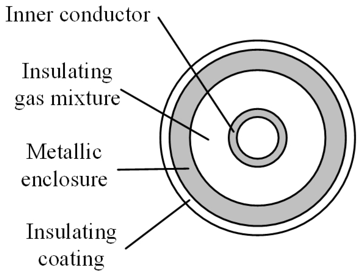
Figure 2.
Typical structure of cross-connection grounding.

Figure 3.
Diagram of a GIL arranged in parallel.

Figure 4.
Single-phase PI-circuit.

Figure 5.
Current-controlled voltage source.

Figure 6.
Voltage-controlled current source.

Figure 7.
GIL equivalent model based on PI-model.

Figure 8.
GIL simplified model based on PI-model.
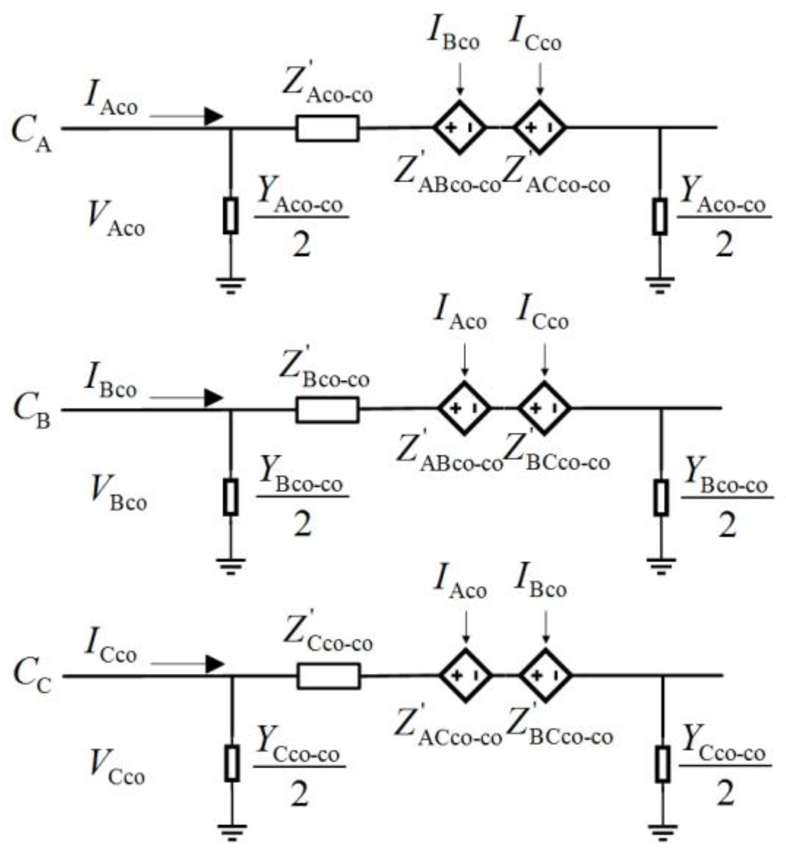
Figure 9.
Waveforms of currents flowing through the GIL equivalent and simplified model: (a) Phase A currents; (b) Phase B currents; (c) Phase C currents.
Figure 9.
Waveforms of currents flowing through the GIL equivalent and simplified model: (a) Phase A currents; (b) Phase B currents; (c) Phase C currents.

Table 1.
Typical dimensions of an 800 kV GIL.
| Parameters | Values | |
|---|---|---|
| Metallic enclosure | inner diameter | 660.0 mm |
| thickness | 8.0 mm | |
| Inner conductor | outer diameter | 177.8 mm |
| thickness | 12.7 mm | |
| Insulating coating | thickness | 3.0 mm |
| phase distance | 1.5 m | |
Table 2.
Parameters of a 1000 kV GIL.
| Parameters | Values | |||
|---|---|---|---|---|
| Inner Conductor | Insulating Gas | Metallic Enclosure | Insulating Coating | |
| Internal diameter | 240 mm | 260 mm | 680 mm | 710 mm |
| External diameter | 260 mm | 680 mm | 710 mm | 715 mm |
| Resistivity | 4 × 10⁻⁸Ω/m | - | 5 × 10⁻⁸Ω/m | - |
| Permeability | μ0 | μ0 | μ0 | μ0 |
| Permittivity | - | ε0 | - | 2.3ε0 |
Table 3.
Measured currents at the first group of voltages.
| Parameters | Values | ||
|---|---|---|---|
| Phase A | Phase B | Phase C | |
| Voltage (kV) | 1000∠0° | 1020∠−120° | 970∠120° |
| Current1 (kA) | 8.9234∠−71.81° | 13.3298∠153.82° | 8.8854∠16.12° |
| Current2 (kA) | 9.0403∠−72.19° | 13.3411∠153.37° | 8.8515∠15.93° |
| Error | 1.31% | 0.08% | 0.38% |
Table 4.
Measured currents at the second group of voltages.
| Parameters | Values | ||
|---|---|---|---|
| Phase A | Phase B | Phase C | |
| Voltage (kV) | 1025∠20° | 1100∠250° | 970∠120° |
| Current1 (kA) | 10.2285∠−51.03° | 14.2726∠163.81° | 10.0248∠15.35° |
| Current2 (kA) | 10.5271∠−50.74° | 14.6787∠163.33° | 10.1589∠14.32° |
| Error | 2.92% | 2.85% | 1.34% |
Table 5.
Measured currents at the third group of voltages.
| Parameters | Values | ||
|---|---|---|---|
| Phase A | Phase B | Phase C | |
| Voltage (kV) | 970∠230° | 900∠−10° | 1100∠−250° |
| Current1 (kA) | 8.9053∠123.78° | 11.6618∠−96.05° | 9.9951∠36.84° |
| Current2 (kA) | 8.9374∠122.40° | 12.0098∠−97.23° | 10.2952∠36.97° |
| Error | 0.36% | 2.98% | 3.00% |
© 2017 by the authors. Licensee MDPI, Basel, Switzerland. This article is an open access article distributed under the terms and conditions of the Creative Commons Attribution (CC BY) license (http://creativecommons.org/licenses/by/4.0/).
Share and Cite
MDPI and ACS Style
Li, B.; Gu, T.; Li, B.; Zhang, Y. Study on the Gas-Insulated Line Equivalent Model and Simplified Model. Energies 2017, 10, 901. https://doi.org/10.3390/en10070901
AMA Style
Li B, Gu T, Li B, Zhang Y. Study on the Gas-Insulated Line Equivalent Model and Simplified Model. Energies. 2017; 10(7):901. https://doi.org/10.3390/en10070901
Chicago/Turabian StyleLi, Botong, Tianfeng Gu, Bin Li, and Yunke Zhang. 2017. "Study on the Gas-Insulated Line Equivalent Model and Simplified Model" Energies 10, no. 7: 901. https://doi.org/10.3390/en10070901
Note that from the first issue of 2016, this journal uses article numbers instead of page numbers. See further details here.