
An Overview of Resonant Circuits for Wireless Power Transfer


1
Department of Electrical and Electronic Engineering, The University of Hong Kong, Hong Kong, China
2
School of Energy and Environment, City University of Hong Kong, Hong Kong, China
3
Research Laboratory of Electronics, Massachusetts Institute of Technology, Cambridge, MA 02139, USA
*
Author to whom correspondence should be addressed.
Energies 2017, 10(7), 894; https://doi.org/10.3390/en10070894
Submission received: 1 April 2017
/
Revised: 25 June 2017
/
Accepted: 27 June 2017
/
Published: 30 June 2017
(This article belongs to the Special Issue Advanced Electric Devices and Technologies for Electric-Drive Robotics)
Abstract
:With ever-increasing concerns for the safety and convenience of the power supply, there is a fast growing interest in wireless power transfer (WPT) for industrial devices, consumer electronics, and electric vehicles (EVs). As the resonant circuit is one of the cores of both the near-field and far-field WPT systems, it is a pressing need for researchers to develop a high-efficiency high-frequency resonant circuit, especially for the mid-range near-field WPT system. In this paper, an overview of resonant circuits for the near-field WPT system is presented, with emphasis on the non-resonant converters with a resonant tank and resonant inverters with a resonant tank as well as compensation networks and selective resonant circuits. Moreover, some key issues including the zero-voltage switching, zero-voltage derivative switching and total harmonic distortion are addressed. With the increasing usage of wireless charging for EVs, bidirectional resonant inverters for WPT based vehicle-to-grid systems are elaborated.
1. Introduction
With the objectives to achieve no power cables, no sparking hazards, better convenience and high flexibility, wireless power transfer (WPT) has attracted considerable attention in many industrial applications and interdisciplinary areas [1,2,3]. As one of the most prominent technologies, the WPT is changing the conventional usage of energy in daily life for human being. In addition, it shows great potential for various applications, such as portable electronic devices [4], medical instruments [5], non-accessible electronics [6], heating [7], electric vehicles (EVs) [8,9,10] including the stationary charging [11], dynamic move-and-charge [12] and in-wheel motor drive [13].
Regarding to the power transmission distance, the WPT could be categorized into two major groups, namely the far-field and the near-field transmission. The far-field transmission should be mainly designed for low-power applications with lower priority of transmission efficiency. In general, the far-field transmission is implemented with microwave or laser through a direct line-of-sight transmission path [14]. Taking the efficiency and the human exposure safety into consideration [15], the far-field transmission should not be a good option for power transmission in our daily lives.
Due to the high efficiency and less radiofrequency exposure safety limit, near-field transmission is a better option as compared to microwave or laser transmission [16]. In particular, the inductive power transfer (IPT), capacitive power transfer (CPT) and permanent magnet coupling (PMC) are the most popular near-field WPT technologies [17,18,19]. Moreover, based on the resonance of magnetic and electric fields in the LC circuit, the use of magnetic resonant coupling (MRC) for IPT has become dominant in the WPT system [20,21]. For the near-field transmission, it could be further divided as two sub-groups, namely the short-range and mid-range transmissions. In general, the short-range near-field WPT indicates that the transmitter and receiver are at a distance of a few centimeters based on the two-coil approach. For these short-range applications, the operating frequency of the resonant circuit is usually in the range of 10 kHz to several megahertz [22]. Normally, the energy dissipation in the power inverter increases with the operating frequency.
With the increase of the air-gap in the mid-range near-field transmission, less magnetic flux linkage can be captured by the receiver coil [23]. By inserting intermediate resonators with the same resonant frequency at the transmitter coil and the receiver coil, wide air-gap power transmission can be facilitated efficiently [24,25]. Moreover, the structure of such coil arrays has been investigated to strengthen the efficiency via stronger resonant coupling in the mid-range near-field applications [26]. Using a high operating frequency in excess of 10 MHz can improve the system quality factor, which leads to higher transmission efficiency in the mid-range WPT system. However, such high-frequency operation will substantially increase the switching losses in the driving circuits.
In previous review papers on WPT, they were focused on describing the historical development of WPT from the late 1890s, from far field to near field and from the challenges to the advances [16,27]. For better utilization of WPT in the mid-range transmission, the impedance matching issues, relay and domino resonators topologies were summarized [28,29]. Due to the emerging market of EVs, the wireless charging of EVs, including roadway powered EVs (RPEVs) and stationary charging EVs (SCEVs), was placed in the spotlight to deal with green transportation [30]. Specifically, several generations of the RPEVs, also dubbed as online EVs, were reviewed, with emphasis on their core types, coil structures, and switching techniques [31]. For the SCEVs, different WPT systems, including the IPT, CPT, and PMC, were also discussed [32]. However, a review of power electronic circuitry for WPT is absent in literature. As the circuitry is one of the core technologies for WPT and has undergone an active development in past decades, a comprehensive overview of this technology is highly desirable.
The purpose of this paper is to give an overview of resonant circuits for the near-field WPT system. The state-of-the-art technology of these resonant circuits, including the non-resonant converters with a resonant tank and resonant inverters, will be reviewed and discussed. In the meantime, the compensation networks and selective power transfer will also be presented.
In Section 2, the non-resonant converters with a resonant tank will be discussed. Then, various resonant inverters including their topologies and operations will be discussed in Section 3. In Section 4, four basic compensation networks and two advanced compensation networks, namely the LCC and LCL, will be presented. In Section 5, based on selective resonant circuits, typical selective WPT applications will be discussed. The development trends of resonant circuits will also be revealed in Section 6. Finally, a conclusion will be drawn in Section 7.
2. Non-Resonant Converters with Resonant Tank
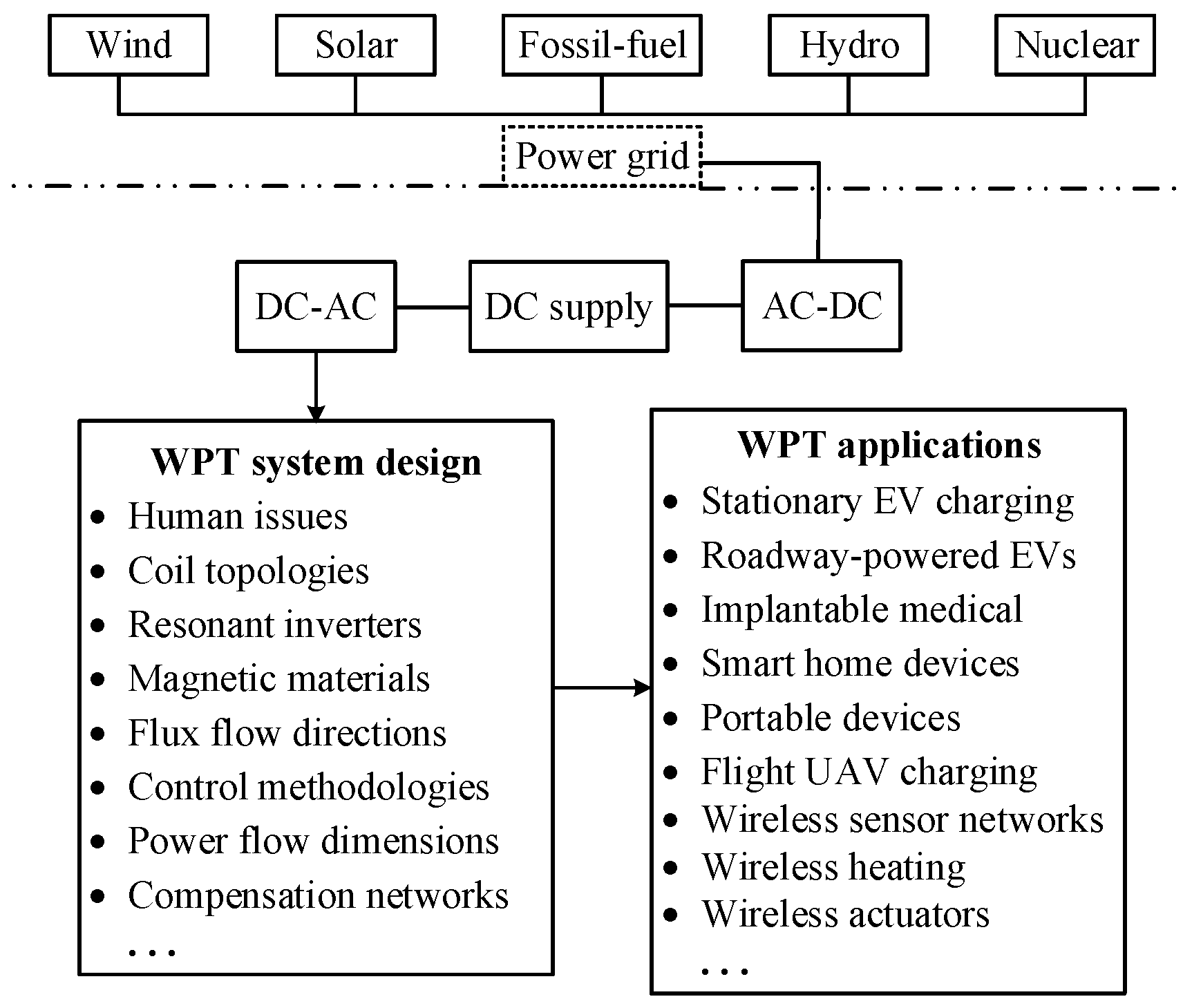
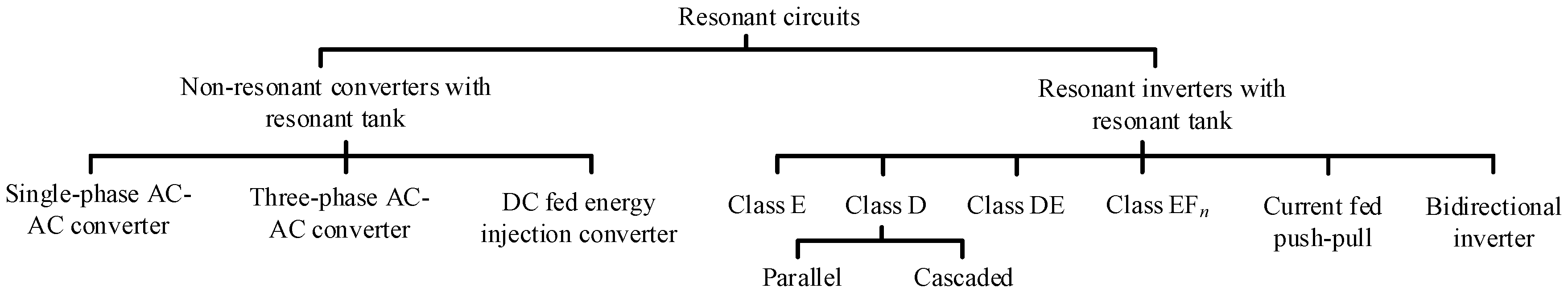
There are numerous WPT applications as shown in Figure 1. Among them, the AC-DC-AC power conversion is widely used in the primary side which involves an AC-DC converter in series with a DC-AC converter (commonly called an inverter). The AC-DC converter serves to convert the AC power from the grid to stable DC power. Then, the inverter produces high-frequency AC power to feed the resonant circuit where it is classified as the resonant inverter as shown in Figure 2. Obviously, this two-stage topology shows some drawbacks such as the costly and bulky DC-link, and higher switching losses. In order to eliminate the DC-link, the direct one-stage AC-AC converter is a good option for providing the desired high-frequency AC power.
2.1. Single-Phase AC-AC Converter
The single-phase AC-AC converter is shown in Figure 3a, which is based on free oscillation and energy-injection control. This one-stage converter can simplify the controller design with a low switching frequency without reverse power flow [33]. The switches S1 and S2 are mainly used to control the power flow, and the S3 and S4 operate to constitute the resonant loop during the S1 and S2 OFF.
The number of oscillations can be controlled by the switching frequency of S1 and S2. In the meantime, the ratio of the nominal resonant frequency to the switching frequency can be used to control the power flowing into the resonant circuit. A variable-frequency method can be applied to follow the circuit resonance, which makes the switching operation achieve zero-current switching (ZCS) easily [34]. This topology takes the definite advantage that the DC link and its bulky energy-storage element can be eliminated [35]. However, current sags around the zero-crossing points of the AC source are inevitable.
2.2. Three-Phase AC-AC Converter
Normally, the single-phase AC-AC converter suffers from great current sags around the AC source zero-crossings, especially under a high ratio of the nominal resonant frequency to the switching frequency. For some three-phase AC source applications, a similar one-stage AC-AC converter can be structured based on the same principle of free oscillation and energy injection control.
The three-phase AC-AC converter as shown in Figure 3b incorporates a matrix converter with six reverse-blocking switches and one regular MOSFET or IGBT. The operation includes eight modes with six energy-injection modes and two free oscillation modes [36,37]. Basically, the energy injection control is the same as that of the single-phase AC-AC converter. Aiming to avoid the voltage zero-crossing, the LC tank terminals are altered between the most positive and the most negative input phases.
Significantly, by controlling the energy injected into the LC tank accumulated in each half-cycle of the resonant current until reaching the reference value, the output current, voltage and power regulation control can be realized [38]. Naturally, this converter inherits the advantages of the single-phase AC-AC converter, but with better current sags and higher power capability. Since the number of power switches increases, the control difficulty rises inevitably.
2.3. DC Fed Energy Injection Converter
Another non-resonant converter, the DC fed energy injection converter, is depicted in Figure 3c where the resonant circuit is used as an intermediate energy storage element [39]. The energy is injected into the LC tank when the switch S1 is turned off. At the beginning, the switch S1 is turned on to charge the inductor LD with the current increasing at the rate of VDC/LD for several cycles of the LC resonance [40]. After the S1 is turned off, the energy is injected into the CD so that the LC tank performs oscillations via the CP, LP and D1.
Unlike the conventional inverter, the operating frequency of the LC tank is no longer determined by the switching frequency. This topology takes the advantage that the switching frequency can be lower than the nominal resonant frequency of the LC tank, which helps reduce the switching losses. However, the overall transmission efficiency and power level are limited by the energy reflow during the damping oscillation; consequently, the output voltage is unstable.
The three mentioned non-resonant converters boost the resonant frequency equivalently with a lower switching frequency for some switches. A comparison of these three non-resonant inverters is shown in Table 1. However, they suffer from a common drawback that high current ripples in the resonant tank are inevitable during the energy oscillation.
3. Resonant Inverters with Resonant Tank
For most WPT applications, the one-stage AC-AC converter with resonant tank is not suitable mainly due to its high control difficulty and unstable output. Thus, the DC-link buffer is necessary to improve the system’s power level, stable output, and flexibility. With the help of DC-link, the resonant circuit can be driven at the resonant frequency by using resonant inverters.
3.1. Class E Resonant Inverter
The Class E resonant inverter topology is the same as the DC fed energy injection converter but employing a special switching technique as shown in Figure 3c. Normally, the Class E resonant inverter is driven at the nominal resonant frequency of LC tank without DC energy injection. The simplified single switch structure is famous for the high efficiency at high operating frequency and high power level to several kilowatts [41]. By optimizing the circuit parameters properly, it is guaranteed that the transistor S1 is switched ON with zero-voltage switching (ZVS) and zero-voltage derivative switching (ZVDS), and therefore the switching losses and stresses are reduced significantly [42,43].
For high power level WPT applications, this topology can control the output power via manipulating the duty cycle control or varying the switching frequency with an efficiency sacrifice [44]. However, the main disadvantage of the Class E resonant inverter is its high peak voltage across the switch, reaching up to 3.5 times DC voltage at a duty cycle of 0.5. Consequently, less power will be produced by the Class E inverter than other resonant inverters with the same voltage and current stresses. For some high DC power supply occasions, the high peak voltage may result in efficiency drop or permanent damage to the inverter
3.2. Class D and Class DE Resonant Inverters
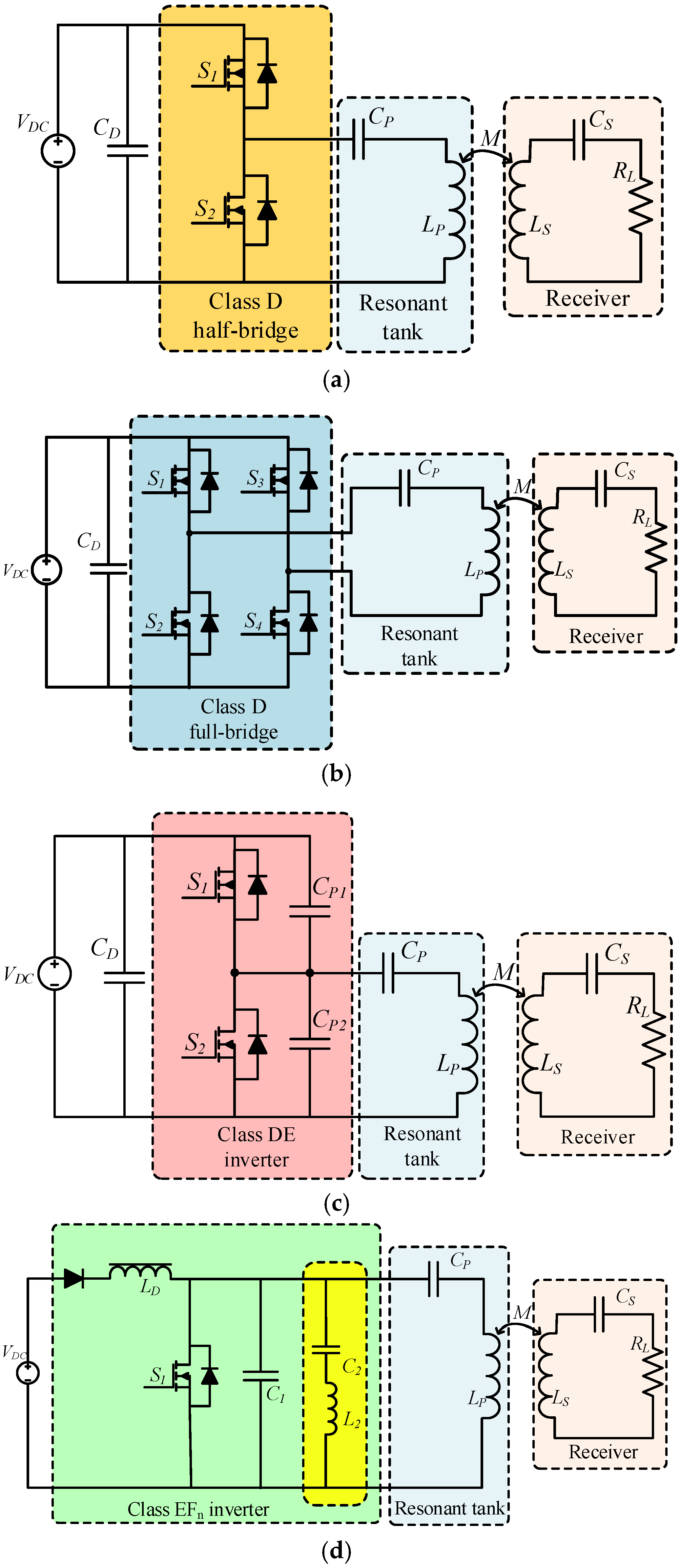
Due to easy system parameter design, the Class D and full-bridge Class D resonant inverters are most popular for practical WPT systems [45], as shown in Figure 4a,b respectively. The Class D inverter employs two switches and a series-resonant LC tank, which results in lower switching frequency than the Class E inverter. It should be noted that the peak voltage across the switch in the full-bridge Class D is as twice higher as the DC supply voltage. Thus, this topology can output twice the voltage to feed the LC resonant circuit, especially suitable for low DC supply WPT applications. Obviously, the Class D resonant inverter with two switches has lower voltage stress across the switch since the peak voltage is as high as the DC supply.
By combining the lower switching stress of Class D and high efficiency of Class E [46], the Class DE topology is created as shown in Figure 4c. The Class DE inverter is quite similar to the Class D inverter, only with two additional parallel-connected capacitors [47]. Thus, the Class DE inverter realizes low switching voltage within the DC supply to reduce the switching losses. Furthermore, the shunt capacitors enable high-frequency operation with ZVS and ZVDS.
3.3. Class EFn Resonant Inverter
In order to inherit the advantages of the Class E inverter and reduce the number of switches, an inverter topology called the Class EFn was proposed as shown in Figure 4d. It consists of a choke inductor LD, shunt capacitor C1, and two parallel-connected LC resonant tanks, where the L2C2 resonant tank is tuned to n times the operating resonant frequency f0 of LPCP [48]. Typically, the subscript n is set to two, namely the EF2 resonant inverter. Hence, the peak voltage stress across the switch can be reduced to 2 times the input DC supply. Besides, the class EF2 inverter has a higher power output capability and efficiency than the Class E and other EFn inverters with the same voltage stresses on their switches.
Comparing with the Class D inverter or full-bridge Class D inverter, the Class EF2 inverter can be designed to achieve ZVS and ZVDS, which makes the single switch operate efficiently up to the megahertz range [49]. Other two benefits of this topology are that the switch’s drain voltage and the output current do not contain a second harmonic component, and has an improved electromagnetic interference performance. However, the corresponding feasibility is limited by the requirement of additional resonant tank.
A detailed design method of Class EF2 inverter for WPT has been presented in [50]. Both the primary inverter and the secondary rectifier adopt the Class EF2 inverter topology and operate at 6.78 MHz and 27.12 MHz respectively, hence offering improved efficiency and lower total harmonic distortion (THD).
3.4. Parallel and Cascaded Inverters
In order to provide higher and more flexible output levels for WPT, the parallel inverter with two full-bridge Class D inverters was proposed as shown in Figure 5a. Each full-bridge Class D inverter is controlled by the clamped-mode switching technique, which results in controllable output voltage, rather than by the duty cycle control [51]. By taking the advantage that power is distributed evenly by the parallel inverters, the heat dissipation becomes easier than the single inverter topology. Moreover, active research is being investigated on the conduction angle and phase delay of the two full-bridge Class D inverters to improve the system stability. Furthermore, this topology has high fault-tolerant ability. When one of the parallel bridge is in the open circuit fault, another bridge can still make the system work properly [52]. However, if the fault type is short circuit, there is no option for the LC resonant operating properly except shutting down the whole system.
By the same token, the output power can be enhanced under the same switching capacity by the cascaded inverter [53] as shown in Figure 5b. The cascaded structure has saliency preponderance in terms of reducing the voltage stress and alleviating the harmonic contamination of the output voltage, namely, with a lower THD. Furthermore, more operating modes can be achieved with higher flexibility in the cascaded structure; therefore the switching losses can be reduced effectively [54].
So far, the topology combining the parallel and cascaded topologies has yet not been investigated. The fault-tolerant ability will be further improved with more complicated switching control technique and higher cost.
3.5. Other Resonant Inverters
(1) Current-fed push-pull resonant inverter: In general, the switches in the inverter should be driven by externally controlled signal for WPT applications. Recently, an autonomous current-fed push-pull resonant inverter with ZVS operation was proposed in which the driving signal was generated automatically without external gate control and kept running at the steady state [55], as shown in Figure 5c. In this topology, the startup should be analyzed, since the two switches S1 and S2 tend to turn ON simultaneously once the DC power supply is turned ON. In a practical system, the two switches would not act at the identical speed due to some parameter differences, hence once a switch is ON first, the other one will be turned OFF. However, it is hard to control which switch should be ON first in the startup process. Moreover, the RC circuit with CSi and Ri should be calculated carefully to make sure that the requirements of switching frequency and circuit losses are fulfilled. By using two or more autonomous push-pull resonant inverters with various phase shifts, a rotating magnetic field can be generated for rotary WPT applications [56].
(2) Bidirectional resonant inverter: With the EV wireless charging becoming more and more popular, combining the vehicle-to-grid (V2G) or vehicle-to-home (V2H) technology [57] and the WPT technique is a viable solution for shaving the peak demand in the power grid. In order to charge or discharge EVs in the V2G or V2H system, a current-source bidirectional resonant inverter was developed in [58]. A typical bidirectional resonant inverter for WPT is shown in Figure 5d, and the corresponding wireless charging scheme for V2G and V2H operations is shown in Figure 6. In order to improve the power level and the fault tolerant ability, a bidirectional WPT system consisting of two resonant inverters was also proposed with optimized control method [59,60]. Such structure makes it more effective and suitable to modify the power flow direction.
3.6. Comparison of Resonant Circuits
The aforementioned resonant circuits including the non-resonant converters with resonant tank and the resonant inverters with resonant tank are qualitatively compared as shown in Table 2. This comparison focuses on assessing some key features for WPT, namely the voltage stress, power level, high frequency operation, control difficulty, switching loss, and effective cost.
4. Compensation Networks
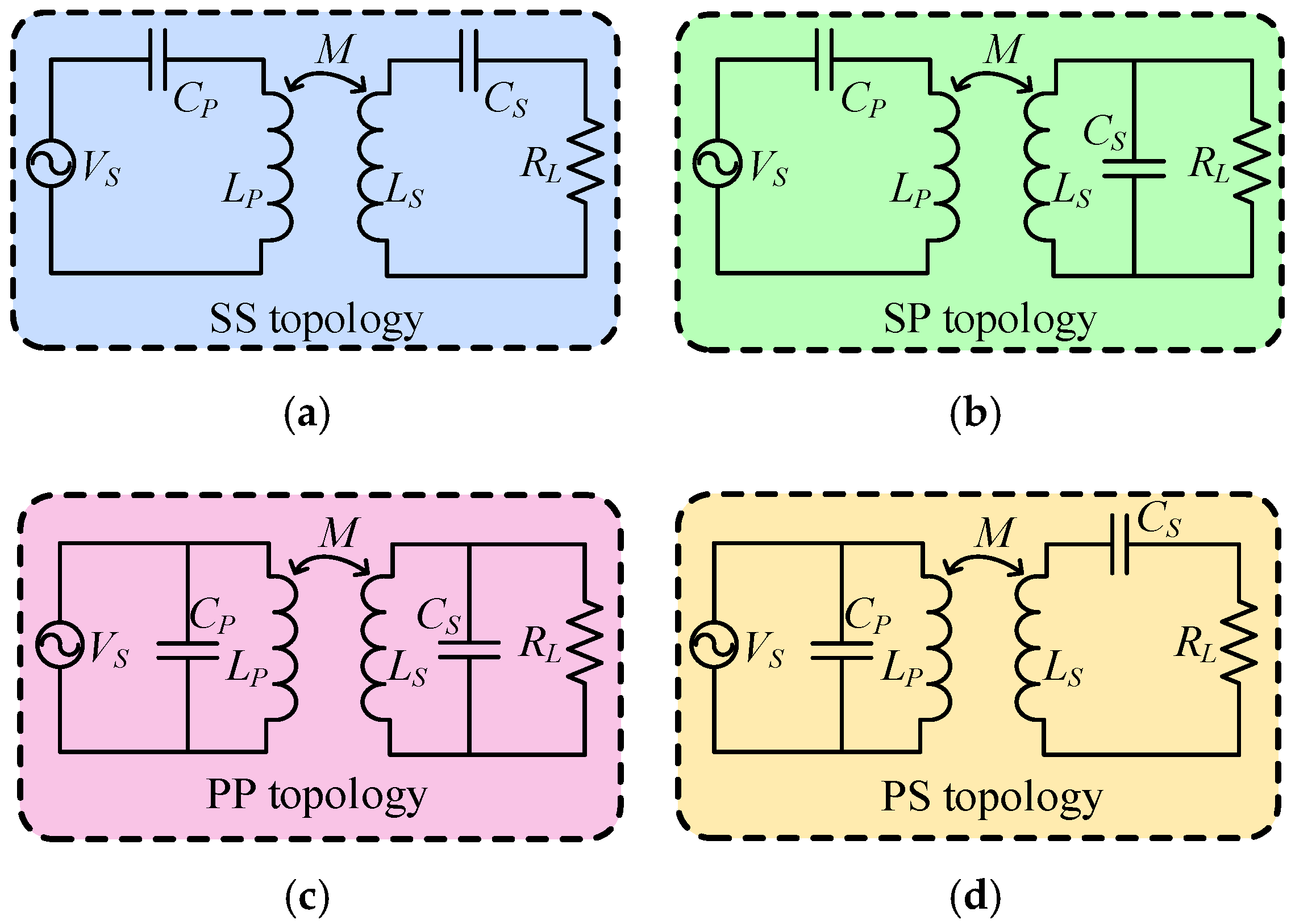
Considering the relationship between the mutual inductance and the coil leakage inductance both in the primary and secondary resonant circuits, various compensation networks are required to optimize the system performance. There are four basic compensation networks, namely the series-series (SS), series-parallel (SP), parallel-series (PS) and parallel-parallel (PP) topologies [61,62,63] as shown in Figure 7. Moreover, the LCC-compensation and LCL-compensation topologies are developed, as shown in Figure 8, aiming to improve the system performance.
4.1. Compensation Topologies in Secondary
The equivalent resonant circuits of the secondary side are shown in Figure 7a,b with series and parallel compensa-tions, respectively, where LP, CP represent the primary coil and primary compensated capacitor, LS, CS represent the secondary coil and secondary compensated capacitor, and RL is the load resistor. The series equivalent resistances of coils and capacitors are neglected to facilitate the analytical derivation. When the current in the secondary coil is IS and in the primary coil is IP, the reflected impedance from the secondary to the primary can be expressed:
where M is the mutual inductance related to the magnetic coupling coefficient k,
The impedance of the secondary side ZS depends on the compensation topology, which can be expressed as:
Normally, the operating frequency is equal to the resonant frequency of the secondary side given by .
According to (1), the reflected impedance is written as the reflected resistance and reactance as listed below:
Generally, the power transferred from the primary side to the secondary side can be regarded as the power consumed by the real component of the reflected impedance, it yields:
From (6), it can be observed that the energy received by the secondary side will decrease quadratically with the mutual inductance; equivalently, the increase of transmission distance.
4.2. Compensation Topologies in Primary
The series- and parallel-compensated primary networks are shown in Figure 7a,c, respectively. The equivalent load impedance regarded by the AC power source is determined by various combinations of the primary and secondary topologies. For the series-compensated primary system, the load impedance ZP can be expressed as:
For the parallel-compensated primary system, the load impedance ZP can be expressed as:
In order to minimize the VA rating of the power supply, normally, the resonant circuits work at the resonant state, where the real component of the load impedance ZP should be zero. Consequently, the zero-phase-angle (ZPA) between the output voltage and current can be achieved. Meanwhile, the ZPA operation will cause more switching loss in the inverter using the hard-switching technique. Practically, the primary side often shifts away from the nominal resonant frequency slightly to realize a small portion of reactive power, which makes the inverter switches operate in ZVS or ZCS.
A comparison of four basic topologies is shown in Table 3. It should be noted that the reflected impedance of the series-compensated secondary includes no reactance. As a result, the nominal resonant frequency in the series-compensated primary will not be affected by the mutual inductance and load variations [63]. In the SP and PP compensated topologies, the mutual inductance variation will shift the nominal resonant frequency of the primary. The high tolerance of SS compensated topology with the system parameters is the main reason for being the most popular choice [64].
Based on the scattering parameter, the transmission efficiency can be calculated as ƞ = |S21|2, where the network is matching at both ports [65]. According to this expression, the transmission efficiency declines rapidly with the increasing distance. The selection of various compensations was analyzed in details in [66], demonstrating that the SS topology is preferred when ω2M2/RL < M2RL/LS2 whereas PP topology is preferred when ω2M2/RL > M2RL/LS2. The features of different topologies are listed in Table 4.
4.3. LCC-Compensation Topology
In order to achieve more flexible operations, such as ZVS, ZCS and ZPA, the LCC compensation was proposed as shown in Figure 8a,b by tuning the compensation network parameters. In the LCC symmetrical T-type compensation network, shown in the primary side of Figure 8a, constant current or constant voltage can be achieved practically regardless of the impedance of the load [67].
The LCC compensation topology is typically designed for a multi-load WPT system, such as the RPEV system [68]. In order to achieve lower turn-off losses and switching stresses, the near ZCS with ZPA was derived for the LCC compensation topology by inserting the series-connected inductor LSP and parallel-connected capacitor CPP [69]. The parameters design procedure with ZCS operation is unlike the conventional topology. First, the nominal primary power PP and resonant frequency ω0 of the secondary side should be determined. Then, the primary coil current IP and the parallel compensation capacitor CPP can be calculated as:
where RF is the reflected resistance from the secondary, Vinverter is output voltage of the inverter.
Consequently, the series-connected inductor LSP and the resonant capacitor CP can be expressed as:
The PP LCC topology was proposed to improve the transmission distance [70]. The maximum transmission efficiency can be harvested within a certain distance by changing the ratio of series- and parallel-connected compensation capacitors. Nevertheless, the main drawback is that the system performance is sensitive to parameter changes.
4.4. LCL-Compensation Topology
Moreover, the reflected capacitive reactance in the PP topology can be tuned out by the series-connected inductor as shown in Figure 8c. There are several advantages for the LCL compensation networks. One is that the converter for LCL only supplies the active power required by the load when the system is under the resonant frequency. The LCL resonant tank is supplied by a DC voltage source, it leads to a major advantage that the output current is directly related to the input voltage supply and independent of the load variation. These make the controller design more simplified and easy to regulate the output power. Besides, the LCL topology can be operated with continuous and discontinuous current [71]. Furthermore, inverter working close to unity power factor (UPF) can be achieved by variable frequency control method.
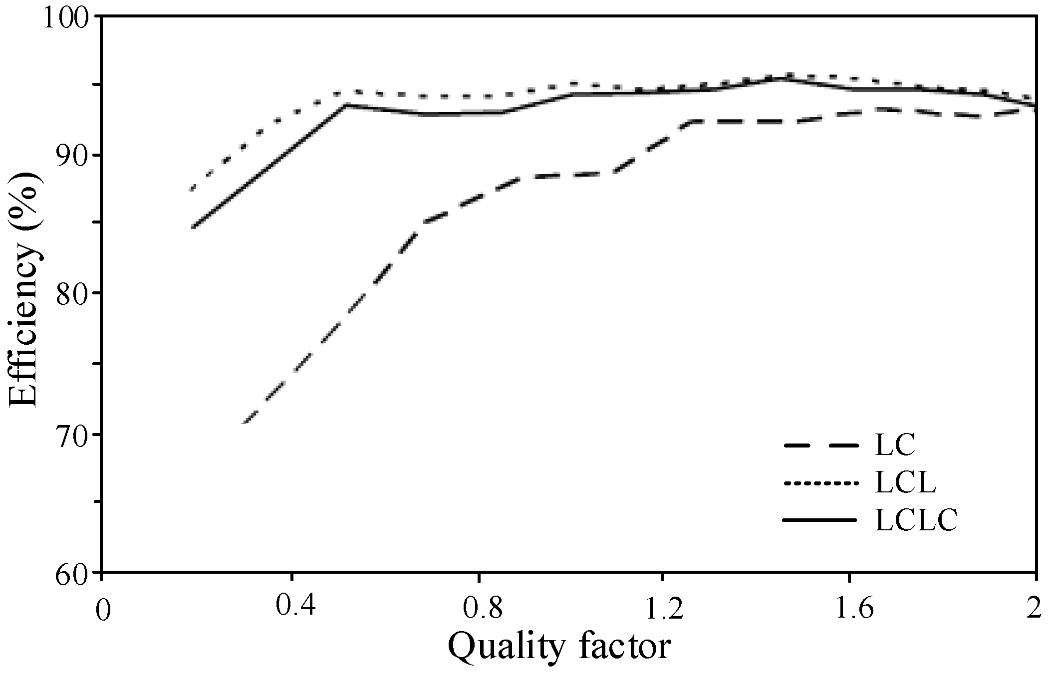
As the LCL topology remains high transmission efficiency at low-quality factor Q, it is more preferred in high-power applications. In order to achieve operation closer to the UPF, normally, an additional series compensation capacitor can be added in series with LR as shown in Figure 8c to compose the LCLC topology, which help the circuit block DC current from flowing in the inductor. However, the inductor saturation is easy to occur in high power applications due to heavy and high frequency current [72]. A comparison of efficiency versus Q with various topologies is shown in Figure 9. It can be observed that the efficiencies of LCL and LCLC topologies are higher than the LC topology. In this LCL topology, the major concern is that the receiver coil should be fixed relative to the transmitter coil, namely, the system has low tolerance ability of position variations.
5. Selective Resonant Circuits
Based on the variation of the compensation capacitor, different resonant frequencies can be tuned or controlled in a real-time mode. Thus, the resulting selective resonant circuits can be utilized for some specific applications such as the targeted WPT.
5.1. Selective Wireless Power Transfer
Currently, the WPT system for multiple receivers has been widely used to power all devices simultaneously [73]. However, for some practical applications, the selective wireless power transfer is required to feed the targeted receiver [74,75]. In the LC resonant circuit, if the operating frequency deviates from the nominal resonant frequency, there will be an obvious great impedance presented in the circuit. Thus, the transmission efficiency will be very low. By using this characteristic, the power flow path can be diverted to the desired receiver, where distinct resonant frequencies are designed for multiple receivers.
As shown in Figure 10, the primary circuit has a transmitter (Tx) coil in series with a capacitor array which includes various compensation capacitors while each receiver circuit has a receiver (Rx) coil in series with a proper compensation capacitor. After the targeted receiver is predetermined with a certain resonant frequency, the primary circuit calculates the corresponding capacitance to suit the resonant frequency of the targeted receiver. Thus, the targeted receiver has the strongest coupling with the primary to pick up the energy [76].
5.2. Energy Encryption
Based on the principle of selective WPT, the transmitted energy can be encrypted to facilitate targeted WPT. In public WPT applications, especially for EV charging, the energy security issue is extremely important to the electricity provider. No matter what the charging type is, the stationary or dynamic charging, the energy transferred to the unauthorized receiver should be eliminated.
Figure 11 shows a recently developed energy encrypted WPT system, which consists of the primary, resonant and secondary coils [77]. The capacitor arrays are used to adjust the resonant frequency dynamically. Consequently, the energy can be delivered to the authorized receiver effectively while avoiding the energy transferred to the unauthorized receiver. In order to avoid code-breaking, chaotic encryption has been developed [78]. When several receivers are coupled to a single transmitter, the bifurcation phenomena might occur due to the varying reflected impedance in the primary. Under different compensation topologies, the bifurcation behaves different characteristics. Thus, an appropriate resonant converter should be determined to satisfy the desired performance. According to various requirements on power level, loss, cost and operation frequency, the corresponding resonant converter should adopt an appropriate control strategy. For some practical applications, jitter control and hysteric control methods were developed to regulate the power flow [79]. Nevertheless, this energy encryption technique suffers from discontinuous resonant frequency variations due to discrete capacitances of the capacitor array. Also, there are slight power variations in the presence of frequency variations, which need additional control for power regulation.
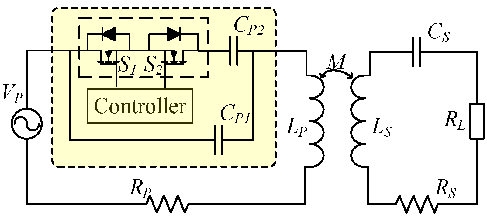
5.3. Online Load Identification
Another application based on switching resonant capacitors is the steady-state load identification online [80]. For some practical applications such as battery charging, the condition of load changes with the charging process. Being aware of the real-time load is the precondition to adjust the operation frequency or other system parameters for achieving the maximum efficiency or power. The online load identification circuit is shown in Figure 12, where the CP1 is the main resonant capacitor series-connected with the coil LP, and the CP2 series-connected with switches S1 and S2 is a dynamic capacitor [81]. The CP1 and LP are to determine the nominal resonant frequency ω0 at the normal mode of operation. The CP2 is to shift the nominal resonant frequency to ω2 at the load identification mode of operation. Based on these two modes of operation, the online measurable parameters can be used to calculate the load and mutual inductance:
where Zr2 and IP2 are the reflected impedance and the primary coil current in the identification mode, respectively.
6. Development Trends
Although fruitful achievements have been made on the development of resonant circuits, resonant inverter topologies and control techniques of the WPT system, there are still many research topics worth being studied:
- (1)
- To develop targeted WPT for electric machines without requiring any energy storage, power electronic circuitry or sensory circuitry in the machine side.
- (2)
- To devise optimized compensation networks or auxiliary circuits, aiming to suppress the power crosstalk between the targeted and nontargeted receivers.
- (3)
- To utilize the parasitic capacitance in the coil to realize the resonant circuit, hence achieving high resonant frequencies for long-distance WPT.
- (4)
- To design high-frequency inverters up to the MHz range while retaining low switching loss, simple gate-driving requirement and reasonable cost.
- (5)
- To develop high-power high-efficiency bidirectional inverters for WPT, hence realizing V2G operation without physical contacts.
- (6)
- To integrate wireless power transfer and wireless information transfer into the same channel to form the wireless power and information transfer (WPIT), hence manipulating power and control simultaneously.
7. Conclusions
In this paper, an overview of the resonant circuits for WPT has been presented, with emphasis on non-resonant converters, resonant inverters, compensation networks and the selective resonant circuits. Their characteristics and key features, such as the operation frequency, power level, fault-tolerant ability, ZVS, ZCS and ZVDS are summarized with advantages and drawbacks. It is anticipated that the high frequency and high power level inverters for WPT system will be the major research direction such as in the long-distance targeted WPT or the emerging WPT for EV charging.
Acknowledgments
This work was supported by a grant (Project No. 201511159096) from The University of Hong Kong, Hong Kong Special Administrative Region, China.
Author Contributions
Chaoqiang Jiang and K. T. Chau carried out the analysis and wrote this paper. Chunhua Liu and Christopher H. T. Lee helped obtain the literatures and made important suggestions.
Conflicts of Interest
The authors declare no conflict of interest.
References
- Covic, G.A.; Boys, J.T. Inductive power transfer. Proc. IEEE 2013, 101, 1276–1289. [Google Scholar] [CrossRef]
- Li, Y.; Mai, R.; Lin, T.; Sun, H.; He, Z. A novel wpt system based on dual transmitters and dual receivers for high power applications: Analysis, design and implementation. Energies 2017, 10, 174. [Google Scholar] [CrossRef]
- Jang, Y.J.; Jeong, S.; Lee, M.S. Initial energy logistics cost analysis for stationary, quasi-dynamic, and dynamic wireless charging public transportation systems. Energies 2016, 9, 783. [Google Scholar] [CrossRef]
- Wu, R.; Li, W.; Luo, H.; Sin, J.K.; Yue, C.P. Design and characterization of wireless power links for brain–machine interface applications. IEEE Trans. Power Electron. 2014, 29, 5462–5471. [Google Scholar] [CrossRef]
- RamRakhyani, A.K.; Mirabbasi, S.; Chiao, M. Design and optimization of resonance-based efficient wireless power delivery systems for biomedical implants. IEEE Trans. Biomed. Circuits Syst. 2011, 5, 48–63. [Google Scholar] [CrossRef] [PubMed]
- Liu, C.; Chau, K.T.; Zhang, Z.; Qiu, C.; Li, W.; Ching, T. Wireless power transfer and fault diagnosis of high-voltage power line via robotic bird. J. Appl. Phys. 2015, 117, 17D521. [Google Scholar] [CrossRef]
- Han, W.; Chau, K.T.; Zhang, Z. Flexible induction heating using magnetic resonant coupling. IEEE Trans. Ind. Electron. 2016, 64, 1982–1992. [Google Scholar] [CrossRef]
- Zhang, Z.; Chau, K.T. Homogeneous wireless power transfer for move-and-charge. IEEE Trans. Power Electron. 2015, 30, 6213–6220. [Google Scholar] [CrossRef]
- Hwang, K.; Cho, J.; Kim, D.; Park, J.; Kwon, J.K.; Kwak, S.I.; Park, H.H.; Ahn, S. An autonomous coil alignment system for the dynamic wireless charging of electric vehicles to minimize lateral misalignment. Energies 2017, 10, 315. [Google Scholar] [CrossRef]
- Shekhar, A.; Prasanth, V.; Bauer, P.; Bolech, M. Economic viability study of an on-road wireless charging system with a generic driving range estimation method. Energies 2016, 9, 76. [Google Scholar] [CrossRef]
- Wang, Z.; Wei, X.; Dai, H. Design and control of a 3 kW wireless power transfer system for electric vehicles. Energies 2016, 9, 10. [Google Scholar] [CrossRef]
- Choi, S.Y.; Gu, B.W.; Jeong, S.Y.; Rim, C.T. Advances in wireless power transfer systems for roadway-powered electric vehicles. IEEE J. Emerg. Sel. Top. Power Electron. 2015, 3, 18–36. [Google Scholar] [CrossRef]
- Sato, M.; Yamamoto, G.; Gunji, D.; Imura, T.; Fujimoto, H. Development of wireless in-wheel motor using magnetic resonance coupling. IEEE Trans. Power Electron. 2016, 31, 5270–5278. [Google Scholar] [CrossRef]
- Marian, V.; Allard, B.; Vollaire, C.; Verdier, J. Strategy for microwave energy harvesting from ambient field or a feeding source. IEEE Trans. Power Electron. 2012, 27, 4481–4491. [Google Scholar] [CrossRef]
- Lin, J.C. A new IEEE standard for safety levels with respect to human exposure to radio-frequency radiation. IEEE Antennas Propag. Mag. 2006, 48, 157–159. [Google Scholar] [CrossRef]
- Garnica, J.; Chinga, R.A.; Lin, J. Wireless power transmission: From far field to near field. Proc. IEEE 2013, 101, 1321–1331. [Google Scholar] [CrossRef]
- Jiang, C.; Chau, K.T.; Ching, T.W.; Liu, C.; Han, W. Time-division multiplexing wireless power transfer for separately excited DC motor drives. IEEE Trans. Magn. 2017. [Google Scholar] [CrossRef]
- Sample, A.P.; Meyer, D.T.; Smith, J.R. Analysis, experimental results, and range adaptation of magnetically coupled resonators for wireless power transfer. IEEE Trans. Ind. Electron. 2011, 58, 544–554. [Google Scholar] [CrossRef]
- Zhang, H.; Lu, F.; Hofmann, H.; Liu, W.; Mi, C.C. A four-plate compact capacitive coupler design and LCL-compensated topology for capacitive power transfer in electric vehicle charging application. IEEE Trans. Power Electron. 2016, 31, 8541–8551. [Google Scholar]
- Zhang, Y.; Zhao, Z.; Chen, K. Frequency-splitting analysis of four-coil resonant wireless power transfer. IEEE Trans. Ind. Appl. 2014, 50, 2436–2445. [Google Scholar] [CrossRef]
- Zhang, W.; White, J.C.; Abraham, A.M.; Mi, C.C. Loosely coupled transformer structure and interoperability study for ev wireless charging systems. IEEE Trans. Power Electron. 2015, 30, 6356–6367. [Google Scholar] [CrossRef]
- Yoon, I.J.; Ling, H. Investigation of near-field wireless power transfer under multiple transmitters. IEEE Antennas Wirel. Propag. Lett. 2011, 10, 662–665. [Google Scholar] [CrossRef]
- Nair, V.V.; Choi, J.R. An efficiency enhancement technique for a wireless power transmission system based on a multiple coil switching technique. Energies 2016, 9, 156. [Google Scholar] [CrossRef]
- Ahn, D.; Hong, S. A study on magnetic field repeater in wireless power transfer. IEEE Trans. Ind. Electron. 2013, 60, 360–371. [Google Scholar] [CrossRef]
- Zhang, J.; Cheng, C. Analysis and optimization of three-resonator wireless power transfer system for predetermined-goals wireless power transmission. Energies 2016, 9, 274. [Google Scholar] [CrossRef]
- Zhong, W.; Lee, C.K.; Hui, S.Y.R. Wireless power domino-resonator systems with noncoaxial axes and circular structures. IEEE Trans. Power Electron. 2012, 27, 4750–4762. [Google Scholar] [CrossRef]
- Mayordomo, I.; Dräger, T.; Spies, P.; Bernhard, J.; Pflaum, A. An overview of technical challenges and advances of inductive wireless power transmission. Proc. IEEE 2013, 101, 1302–1311. [Google Scholar] [CrossRef]
- Hui, S.Y.R.; Zhong, W.; Lee, C.K. A critical review of recent progress in mid-range wireless power transfer. IEEE Trans. Power Electron. 2014, 29, 4500–4511. [Google Scholar] [CrossRef]
- Barman, S.D.; Reza, A.W.; Kumar, N.; Karim, M.E.; Munir, A.B. Wireless powering by magnetic resonant coupling: Recent trends in wireless power transfer system and its applications. Renew. Sustain. Energy Rev. 2015, 51, 1525–1552. [Google Scholar] [CrossRef]
- Qiu, C.; Chau, K.T.; Ching, T.W.; Liu, C. Overview of wireless charging technologies for electric vehicles. J. Asian Electr. Veh. 2014, 12, 1679–1685. [Google Scholar] [CrossRef]
- Mi, C.C.; Buja, G.; Choi, S.Y.; Rim, C.T. Modern advances in wireless power transfer systems for roadway powered electric vehicles. IEEE Trans. Ind. Electron. 2016, 63, 6533–6545. [Google Scholar] [CrossRef]
- Musavi, F.; Eberle, W. Overview of wireless power transfer technologies for electric vehicle battery charging. IET Power Electron. 2014, 7, 60–66. [Google Scholar] [CrossRef]
- Khan, A.A.; Cha, H.; Ahmed, H.F. High efficiency single-phase AC-AC converters without commutation problem. IEEE Trans. Power Electron. 2016, 31, 5655–5665. [Google Scholar] [CrossRef]
- Sarnago, H.; Lucía, O.; Mediano, A.; Burdío, J.M. Efficient and cost-effective ZCS direct AC-AC resonant converter for induction heating. IEEE Trans. Ind. Electron. 2014, 61, 2546–2555. [Google Scholar] [CrossRef]
- Li, H.L.; Hu, A.P.; Covic, G.A. A direct ac–ac converter for inductive power-transfer systems. IEEE Trans. Power Electron. 2012, 27, 661–668. [Google Scholar] [CrossRef]
- Moghaddami, M.; Anzalchi, A.; Sarwat, A.I. Single-stage three-phase ac-ac matrix converter for inductive power transfer systems. IEEE Trans. Ind. Electron. 2016, 63, 6613–6622. [Google Scholar] [CrossRef]
- Wheeler, P.W.; Rodriguez, J.; Clare, J.C.; Empringham, L.; Weinstein, A. Matrix converters: A technology review. IEEE Trans. Ind. Electron. 2002, 49, 276–288. [Google Scholar] [CrossRef]
- Zhang, Y.; Ruan, X. Three-phase AC-AC converter with controllable phase and amplitude. IEEE Trans. Ind. Electron. 2015, 62, 5689–5699. [Google Scholar] [CrossRef]
- Ju, X.; Dong, L.; Huang, X.; Liao, X. Switching technique for inductive power transfer at high-regimes. IEEE Trans. Ind. Electron. 2015, 62, 2164–2173. [Google Scholar] [CrossRef]
- Del-Aguila-Lopez, F.; Pala-Schonwalder, P.; Molina-Gaudo, P.; Mediano-Heredia, A. A discrete-time technique for the steady-state analysis of nonlinear Class-E amplifiers. IEEE Trans. Circuits Syst. I Regul. Pap. 2007, 54, 1358–1366. [Google Scholar] [CrossRef]
- Liu, M.; Fu, M.; Ma, C. Low-harmonic-contents and high-efficiency Class E full-wave current-driven rectifier for megahertz wireless power transfer systems. IEEE Trans. Power Electron. 2017, 32, 1198–1209. [Google Scholar] [CrossRef]
- Pinuela, M.; Yates, D.C.; Lucyszyn, S.; Mitcheson, P.D. Maximizing DC-to-load efficiency for inductive power transfer. IEEE Trans. Power Electron. 2013, 28, 2437–2447. [Google Scholar] [CrossRef]
- Nagashima, T.; Wei, X.; Bou, E.; Alarcón, E.; Kazimierczuk, M.K.; Sekiya, H. Analysis and design of loosely inductive coupled wireless power transfer system based on class-e2 dc-dc converter for efficiency enhancement. IEEE Trans. Circuits Syst. I Regul. Pap. 2015, 62, 2781–2791. [Google Scholar] [CrossRef]
- Aldhaher, S.; Luk, P.C.; Bati, K.A.; Whidborne, J.F. Wireless power transfer using class e inverter with saturable dc-feed inductor. IEEE Trans. Ind. Appl. 2014, 50, 2710–2718. [Google Scholar] [CrossRef]
- Covic, G.A.; Boys, J.T.; Kissin, M.L.; Lu, H.G. A three-phase inductive power transfer system for roadway-powered vehicles. IEEE Trans. Ind. Electron. 2007, 54, 3370–3378. [Google Scholar] [CrossRef]
- Koizumi, H.; Kurokawa, K. Analysis of the class de inverter with thinned-out driving patterns. IEEE Trans. Ind. Electron. 2007, 54, 1150–1160. [Google Scholar] [CrossRef]
- Nagashima, T.; Wei, X.; Sekiya, H. Analytical design procedure for resonant inductively coupled wireless power transfer system with class-de inverter and class-e rectifier. In Proceedings of the 2014 IEEE Asia Pacific Conference on Circuits and Systems, Ishigaki, Japan, 17–20 November 2014. [Google Scholar] [CrossRef]
- Kaczmarczyk, Z. Modeling and analysis of Class EF and Class E/F inverters with series-tuned resonant networks. IEEE Trans. Ind. Electron. 2006, 53, 1584–1593. [Google Scholar] [CrossRef]
- Aldhaher, S.; Yates, D.C.; Mitcheson, P.D. Modeling and analysis of class ef and class E/F inverters with series-tuned resonant networks. IEEE Trans. Power Electron. 2016, 31, 3415–3430. [Google Scholar] [CrossRef]
- Aldhaher, S.; Mitcheson, P.D.; Yates, D.C. Load-independent Class EF inverters for inductive wireless power transfer. In Proceedings of the 2016 IEEE Wireless Power Transfer Conference, Knoxville, TN, USA, 4–6 October 2016. [Google Scholar] [CrossRef]
- Hao, H.; Covic, G.A.; Boys, J.T. A parallel topology for inductive power transfer power supplies. IEEE Trans. Power Electron. 2014, 29, 1140–1151. [Google Scholar] [CrossRef]
- Schonknecht, A.; De Doncker, R.W. Novel topology for parallel connection of soft-switching high-power high-frequency inverters. IEEE Trans. Ind. Appl. 2003, 39, 550–555. [Google Scholar] [CrossRef]
- Mai, Y.; Li, R.; Yang, M.; He, Z. Cascaded multi-level inverter based IPT systems for high power applications. J. Power Electron. 2015, 15, 1508–1516. [Google Scholar]
- Nguyen, B.X.; Vilathgamuwa, D.M.; Foo, G.; Wang, P.; Ong, A. A modified cascaded multilevel converter topology for high power bidirectional inductive power transfer systems with the reduction of switching devices and power losses. In Proceedings of the 2015 IEEE 11th International Conference on Power Electronics and Drive, Sydney, Australia, 9–12 June 2015; 2015; 15. [Google Scholar] [CrossRef]
- Abdolkhani, A.; Hu, A.P.; Tian, J. Autonomous polyphase current-fed push–pull resonant converter on ring coupled oscillators. IEEE J. Emerg. Sel. Top. Power Electron. 2015, 3, 568–576. [Google Scholar] [CrossRef]
- Abdolkhani, A.; Hu, A.P.; Covic, G.A.; Moridnejad, M. Through-hole contactless slipring system based on rotating magnetic field for rotary applications. IEEE Trans. Ind. Appl. 2014, 50, 3644–3655. [Google Scholar] [CrossRef]
- Liu, C.; Chau, K.T.; Wu, D.; Gao, S. Opportunities and challenges of vehicle-to-home, vehicle-to-vehicle, and vehicle-to-grid technologies. Proc. IEEE 2013, 101, 2409–2427. [Google Scholar] [CrossRef]
- Madawala, U.K.; Thrimawithana, D.J. A bidirectional inductive power interface for electric vehicles in V2G systems. IEEE Trans. Ind. Electron. 2011, 58, 4789–4796. [Google Scholar] [CrossRef]
- Neath, M.J.; Swain, A.K.; Madawala, U.K.; Thrimawithana, D.J. An optimal pid controller for a bidirectional inductive power transfer system using multiobjective genetic algorithm. IEEE Trans. Power Electron. 2014, 29, 1526–1531. [Google Scholar] [CrossRef]
- Swain, A.K.; Neath, M.J.; Madawala, U.K.D.J. Thrimawithana, A dynamic multivariable state-space model for bidirectional inductive power transfer systems. IEEE Trans. Power Electron. 2012, 27, 4772–4780. [Google Scholar] [CrossRef]
- Wang, C.S.; Stielau, O.H.; Covic, G.A. Design considerations for a contactless electric vehicle battery charger. IEEE Trans. Ind. Electron. 2005, 52, 1308–1314. [Google Scholar] [CrossRef]
- Zhang, W.; Wong, S.C.; Chi, K.T.; Chen, Q. Analysis and comparison of secondary series-and parallel-compensated inductive power transfer systems operating for optimal efficiency and load-independent voltage-transfer ratio. IEEE Trans. Power Electron. 2014, 29, 2979–2990. [Google Scholar] [CrossRef]
- Boys, J.; Covic, G.; Green, A.W. Stability and control of inductively coupled power transfer systems. IEE Proc. Electr. Power Appl. 2000, 147, 37–43. [Google Scholar] [CrossRef]
- Zhang, W.; Wong, S.C.; Chi, K.T.; Chen, Q. Design for efficiency optimization and voltage controllability of series–series compensated inductive power transfer systems. IEEE Trans. Power Electron. 2014, 29, 191–200. [Google Scholar] [CrossRef]
- Imura, T.; Hori, Y. Maximizing air gap and efficiency of magnetic resonant coupling for wireless power transfer using equivalent circuit and neumann formula. IEEE Trans. Ind. Electron. 2011, 58, 4746–4752. [Google Scholar] [CrossRef]
- Jiang, W.X.; Chin, J.Y.; Li, Z.; Cheng, Q.; Liu, R.; Cui, T.J. Analytical design of conformally invisible cloaks for arbitrarily shaped objects. Phys. Rev. E 2008, 77, 066607. [Google Scholar] [CrossRef] [PubMed]
- Zhu, Q.; Wang, L.; Guo, Y.; Liao, C.; Li, F. Applying LCC compensation network to dynamic wireless ev charging system. IEEE Trans. Ind. Electron. 2016, 63, 6557–6567. [Google Scholar] [CrossRef]
- Zhang, W.; Mi, C.C. Compensation topologies of high-power wireless power transfer systems. IEEE Trans. Veh. Technol. 2016, 65, 4768–4778. [Google Scholar] [CrossRef]
- Pantic, Z.; Bai, S.; Lukic, S.M. ZCS-compensated resonant inverter for inductive-power-transfer application. IEEE Trans. Ind. Electron. 2011, 58, 3500–3510. [Google Scholar] [CrossRef]
- Chen, L.; Liu, S.; Zhou, Y.C.; Cui, T.J. An optimizable circuit structure for high-efficiency wireless power transfer. IEEE Trans. Ind. Electron. 2013, 60, 339–349. [Google Scholar] [CrossRef]
- Wang, C.S.; Covic, G.A.; Stielau, O.H. Investigating an LCL load resonant inverter for inductive power transfer applications. IEEE Trans. Power Electron. 2004, 19, 995–1002. [Google Scholar] [CrossRef]
- Keeling, N.A.; Covic, G.A.; Boys, J.T. A unity-power-factor IPT pickup for high-power applications. IEEE Trans. Ind. Electron. 2010, 57, 744–751. [Google Scholar] [CrossRef]
- Zhong, W.; Hui, S.Y.R. Auxiliary circuits for power flow control in multifrequency wireless power transfer systems with multiple receivers. IEEE Trans. Power Electron. 2015, 30, 5902–5910. [Google Scholar] [CrossRef]
- Kim, Y.J.; Ha, D.; Chappell, W.J.; Irazoqui, P.P. Selective wireless power transfer for smart power distribution in a miniature-sized multiple-receiver system. IEEE Trans. Ind. Electron. 2016, 63, 1853–1862. [Google Scholar] [CrossRef]
- Zhang, Y.; Lu, T.; Zhao, Z.; He, F.; Chen, K.; Yuan, L. Selective wireless power transfer to multiple loads using receivers of different resonant frequencies. IEEE Trans. Power Electron. 2015, 30, 6001–6005. [Google Scholar] [CrossRef]
- Jiang, C.; Chau, K.T.; Liu, C.; Han, W. Wireless DC motor drives with selectability and controllability. Energies 2017, 10, 49. [Google Scholar] [CrossRef]
- Zhang, Z.; Chau, K.T.; Qiu, C.; Liu, C. Energy encryption for wireless power transfer. IEEE Trans. Power Electron. 2015, 30, 5237–5246. [Google Scholar] [CrossRef]
- Wang, Z.; Chau, K.T.; Liu, C. Improvement of electromagnetic compatibility of motor drives using chaotic PWM. IEEE Trans. Magn. 2007, 43, 2612–2614. [Google Scholar] [CrossRef]
- Neath, M.; Madawala, U.; Thrimawithana, D. Frequency jitter control of a multiple pick-up bidirectional inductive power transfer system. In Proceedings of the IEEE International Conference on Industrial Technology, Cape Town, Western Cape, South Africa, 25–28 February 2013; pp. 521–526. [Google Scholar]
- Wang, Z.H.; Li, Y.P.; Sun, Y.; Tang, C.S.; Lv, X. Load detection model of voltage-fed inductive power transfer system. IEEE Trans. Power Electron. 2013, 28, 5233–5243. [Google Scholar] [CrossRef]
- Su, Y.G.; Zhang, H.Y.; Wang, Z.H.; Hu, A.P.; Chen, L.; Sun, Y. Steady-state load identification method of inductive power transfer system based on switching capacitors. IEEE Trans. Power Electron. 2015, 30, 6349–6355. [Google Scholar] [CrossRef]
Figure 1.
Typical applications of WPT.

Figure 2.
Classification of resonant circuits.

Figure 3.
Non-resonant converters with resonant tank for WPT. (a) Single-phase AC-AC converter; (b) Three-phase AC-AC converter; and (c) DC fed energy injection converter.
Figure 3.
Non-resonant converters with resonant tank for WPT. (a) Single-phase AC-AC converter; (b) Three-phase AC-AC converter; and (c) DC fed energy injection converter.
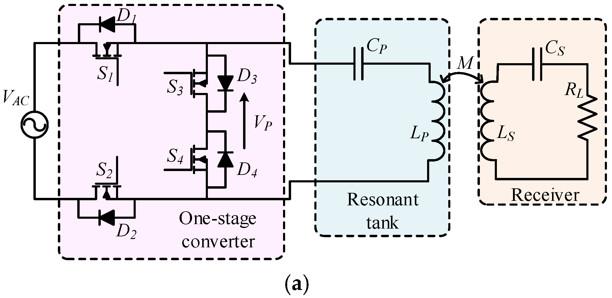
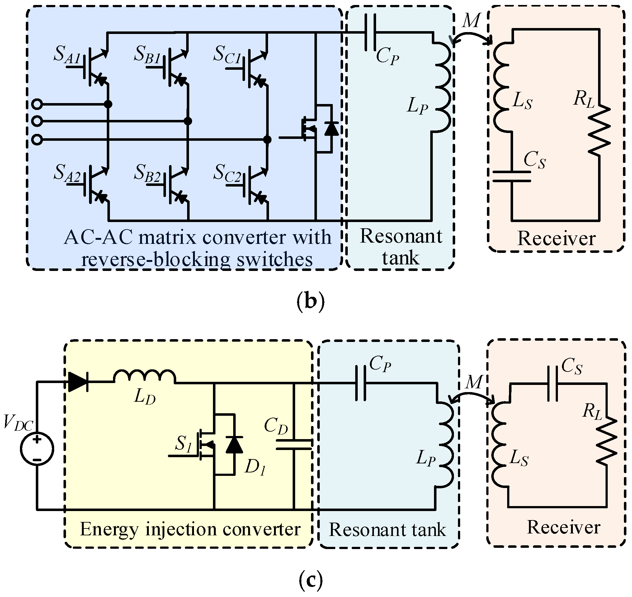
Figure 4.
Resonant inverters with resonant tank for WPT. (a) Class D resonant inverter; (b) Full-bridge Class D resonant inverter; (c) Class DE resonant inverter; and (d) Class EFn resonant inverter.
Figure 4.
Resonant inverters with resonant tank for WPT. (a) Class D resonant inverter; (b) Full-bridge Class D resonant inverter; (c) Class DE resonant inverter; and (d) Class EFn resonant inverter.

Figure 5.
Parallel and cascaded inverters. (a) Parallel full-bridge Class D resonant inverter; (b) Cascaded full-bridge Class D resonant inverter; (c) Current-fed push-pull resonant inverter; and (d) Bidirectional resonant inverter.
Figure 5.
Parallel and cascaded inverters. (a) Parallel full-bridge Class D resonant inverter; (b) Cascaded full-bridge Class D resonant inverter; (c) Current-fed push-pull resonant inverter; and (d) Bidirectional resonant inverter.
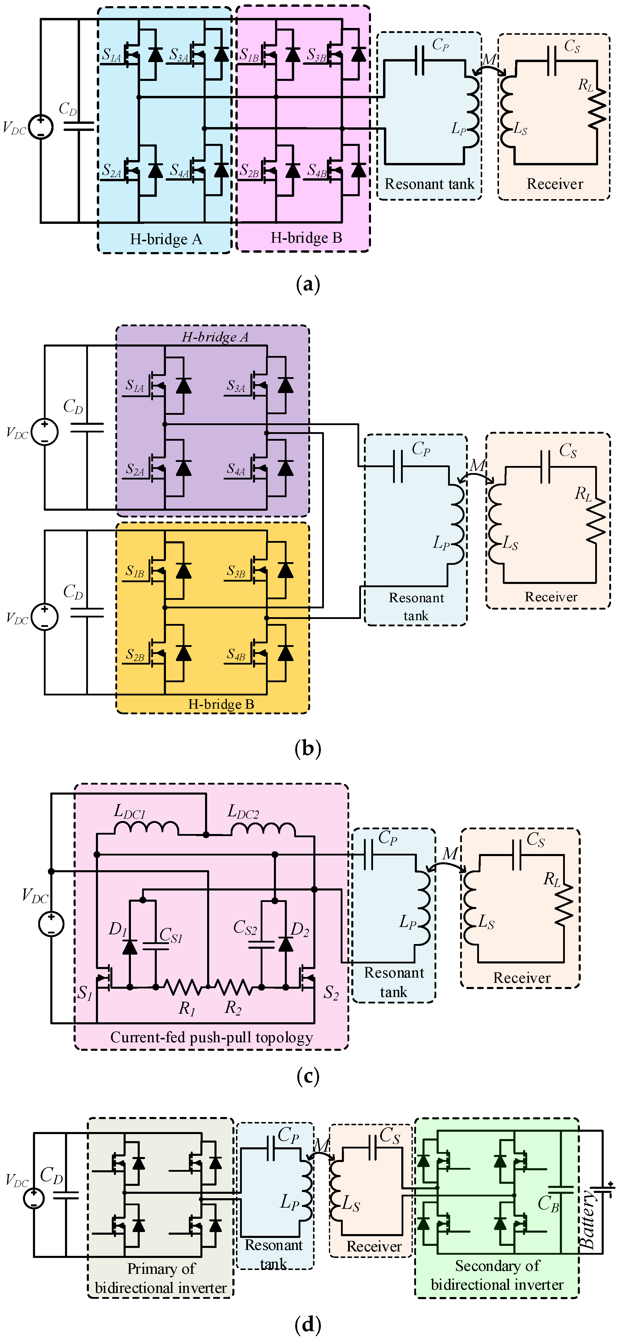
Figure 6.
Wireless charging scheme for V2G and V2H operations.
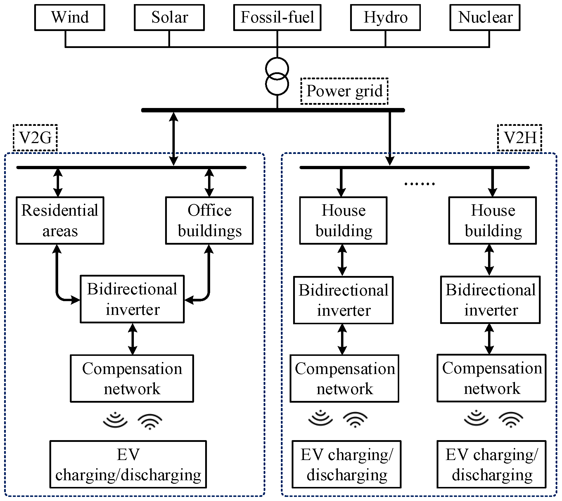
Figure 7.
Basic compensation networks.

Figure 8.
LCC and LCL compensation networks. (a) SS LCC topology; (b) PP LCC; and (c) PP LCL topology.
Figure 8.
LCC and LCL compensation networks. (a) SS LCC topology; (b) PP LCC; and (c) PP LCL topology.
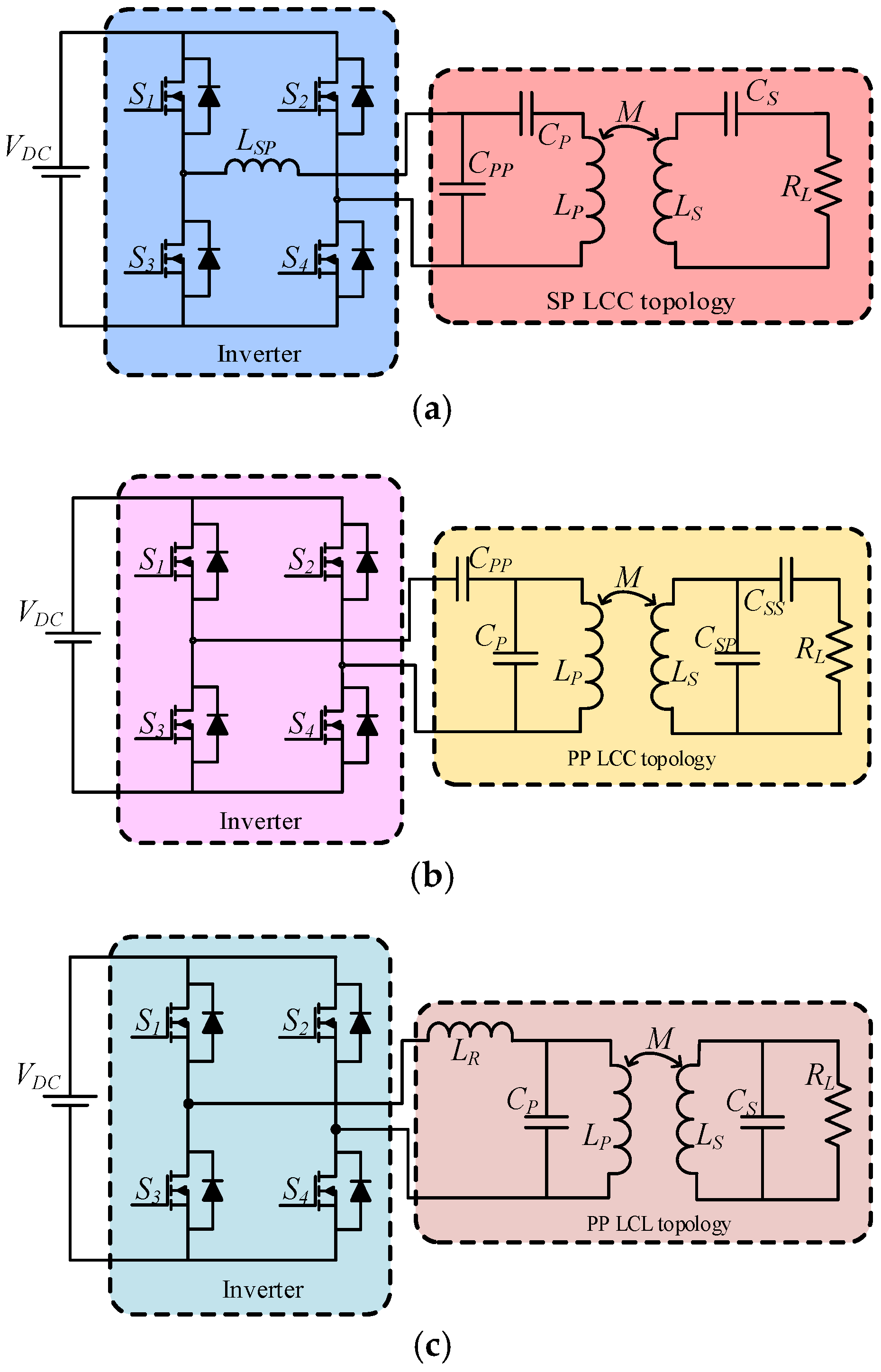
Figure 9.
Comparison of efficiencies of LC, LCL and LCLC topologies.

Figure 10.
Selective WPT system.

Figure 11.
Energy encrypted WPT system.
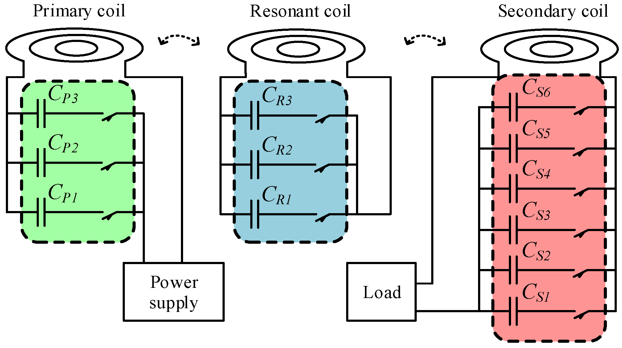
Figure 12.
Online load identification circuit.

Table 1.
Comparison of non-resonant converters with resonant tank for WPT system.
| Single-Phase AC-AC Converter | Three-Phase AC-AC Converter | DC Fed Energy Injection Converter | |
|---|---|---|---|
| Factors |
|
|
|
| Features |
|
|
|
Table 2.
Comparison of resonant circuits for WPT.
| Type | Voltage Stress 1 | Power Level 2 | High Frequency Operation 3 | Control Difficulty | Switching Loss | Effective Cost |
|---|---|---|---|---|---|---|
| Single-phase AC-AC converter | Low | Low | Medium | Medium | Low | Medium |
| Three-phase AC-AC converter | Medium | Medium | Medium | High | Medium | Medium |
| DC fed energy injection converter | Low | Low | High | Medium | Low | Low |
| Class E resonant inverter | High | High | High | Low | Low | Low |
| Class D resonant inverter | Medium | Medium (half-bridge) High (full-bridge) | Medium | Low (half-bridge) Medium (full-bridge) | Medium 4 | Low |
| Class DE resonant inverter | Low | Medium | High | Medium | Low | Medium |
| Class EF2 resonant inverter | Low | Medium | High | Low | Low | Low |
| Current-fed push-pull resonant inverter | Medium | Medium | Medium | NA | Low | Low |
| Parallel resonant inverter | Medium | High | Medium | High | High | High |
| Cascaded resonant inverter | Medium | High | Medium | High | High | High |
1 Voltage stress can range from 1 to 3.5 times voltage supply. 2 Power level can range from 50 W to 20 kW. Generally, medium power level represents power higher than 300 W but lower than several kilowatts, and high power level represents power higher than several kilowatts. 3 Generally, the switching frequency for wireless power transfer is above several dozen kHz, which is in the medium frequency range. In addition, the high frequency can reach several megahertz for some low power applications and far field transmission. 4 Normally, the switching loss with series resonant tank is higher when compared with a parallel resonant tank.
Table 3.
Comparison of four basic topologies.
| Topology | Reflected Resistance | Reflected Reactance | Secondary Quality Factor (QS) |
|---|---|---|---|
| SS | 0 | ||
| SP | |||
| PS | 0 | ||
| PP | |||
| LCC-S * | 0 | ||
| LCL-P * |
* The compensated capacitor CPP and LSP should be calculated depending on the load and output voltage of inverter. Normally, the primary is operated at or near the resonant frequency of the secondary.
Table 4.
Comparison of various compensation topologies for WPT.
| Topology | Features | Topology | Features |
|---|---|---|---|
| SS topology |
| SP topology |
|
| PS topology |
| PP topology |
|
| LCC topology |
| LCL topology |
|
© 2017 by the authors. Licensee MDPI, Basel, Switzerland. This article is an open access article distributed under the terms and conditions of the Creative Commons Attribution (CC BY) license (http://creativecommons.org/licenses/by/4.0/).
Share and Cite
MDPI and ACS Style
Jiang, C.; Chau, K.T.; Liu, C.; Lee, C.H.T. An Overview of Resonant Circuits for Wireless Power Transfer. Energies 2017, 10, 894. https://doi.org/10.3390/en10070894
AMA Style
Jiang C, Chau KT, Liu C, Lee CHT. An Overview of Resonant Circuits for Wireless Power Transfer. Energies. 2017; 10(7):894. https://doi.org/10.3390/en10070894
Chicago/Turabian StyleJiang, Chaoqiang, K. T. Chau, Chunhua Liu, and Christopher H. T. Lee. 2017. "An Overview of Resonant Circuits for Wireless Power Transfer" Energies 10, no. 7: 894. https://doi.org/10.3390/en10070894
Note that from the first issue of 2016, this journal uses article numbers instead of page numbers. See further details here.