Numerical Modelling of Mechanical Behavior of Coal Mining Hard Roofs in Different Backfill Ratios: A Case Study

Key Laboratory of Deep Coal Resources Mining, School of Mines, Ministry of Education of China, China University of Mining & Technology, Xuzhou 221116, China
*
Author to whom correspondence should be addressed.
Energies 2017, 10(7), 1005; https://doi.org/10.3390/en10071005
Submission received: 21 June 2017
/
Revised: 12 July 2017
/
Accepted: 13 July 2017
/
Published: 15 July 2017
Abstract
:In coal mining hard roofs are one of the main factors causing the occurrence of rock bursts in working panels. To solve this problem, the solid backfill coal mining (SBCM) technique is proposed and used as an effective measure to prevent the rock bursts induced by hard roofs. However, due to the different backfill ratios of working planes, the control effects on hard roofs are quite unique. By using a numerical simulation, this study simulates the deformation of hard roofs and distributions of stress and strain energies in different roof-control backfill ratios, so as to reveal the control mechanisms of SBCM on hard roofs. The results show that, when the roof-controlled backfill ratio are 0, 40% and 60%, the ratio exerts no influence on the distributions of advanced abutment stress and strain energies. While for roof-control backfill ratios of 82.5%, 91% and 93%, the advanced abutment stress and strain energies decrease significantly, but the increment of the ratio exerts little influence on the decrease. When the roof-control backfill ratio reaches 97%, the advanced abutment stress and strain energies again decrease. In this context, the stress concentration factor is only 1.5 and the peak strain energy is 544 kJ/m3, the stress concentration factor and peak strain energy decrease by 45.7% and 63.9%, respectively, compared with the caving method. As the roof-controlled backfill ratio rises, backfill materials tend to support hard roofs, thus significantly preventing dynamic hazards.
1. Introduction
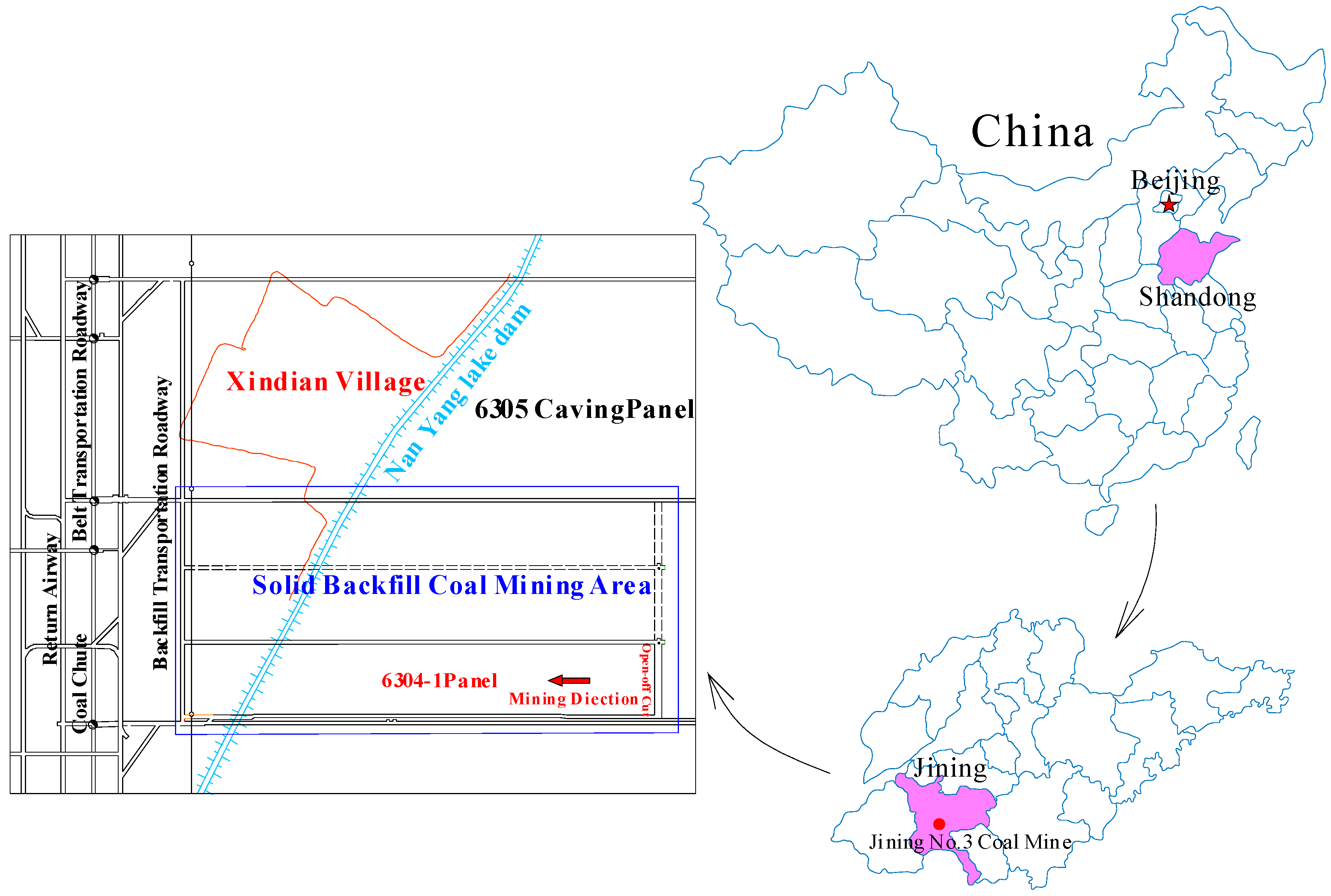
The term hard roofs [1,2] refers to the strata occurring above coal seams or above thin immediate roofs; they have large thicknesses, poor joint development, and high rock strength and bearing capacity. Owing to the significantly variability of hard roof conditions in China, their thickness can vary from tens to hundreds of metres, and the coal resource reserves under hard roofs account for about 30% of overall reserves. At present, nearly 40% of fully mechanised mining panels are under hard roofs and more than 50% of the mining areas in China [3] have hard roofs above the working panels. After mining the working panels, hard roofs are difficult to naturally cave and a large area of hanging roof is formed in goafs [4,5,6]. When the area of hanging roof reaches a certain value, the stress thereon exceeds the bearing capacity, and fractures will occur [7,8,9]. Furthermore, the energy accumulated in roofs and coal seams [10,11] can be released sharply, which is likely to lead to the occurrence of major dynamic hazards in coal mines, including rock bursts [12,13,14], resulting in serious damage to equipment and potentially heavy casualties. For example [15], in the Jining No. 3 coal mine located in Jining City, Shandong Province, China, the longwall mining method is mainly used, and the main roof is mainly composed of extremely thick fine sandstone, which is regarded as a hard roof. On 30 November 2004, a rock burst occurred in the auxiliary crossheading on the 6030 working panel and the 30 m long roadway witnessed the instant outburst of the coal walls over sections of between 1.5 and 2.0 m long, which damaged seven trains carrying power station equipment. While the mining of the adjacent 6304 working panel was stopped in May 2008 due to the existence of obvious signs of an imminent rock burst hazard, about 652 thousand tons of coals cannot be mined from the remaining about 548 m long coal seam. This is evidence that the existence of hard roofs is one of the main factors inducing rock bursts in working panels [16,17].
Scholars across the world have proposed methods such as coal pillar support, strength reduction, and forced caving to control rock bursts in hard roofs [18,19,20]. For the coal pillar support method, the remaining coal pillars are used to support the hard roof, but the coal pillars will creep over time and finally fail. The purpose of the strength reduction and forced caving methods is to make the hard roof break in advance, thus, the mine pressure could be released. Being popular and applied to a certain extent, these methods have achieved good results, however, due to the variability of geological conditions and hard roofs in coal mines, the application conditions and effects of the above methods are limited, for example, when extracting the coal seam beneath buildings, the above methods cannot be used to control both rock bursts and surface subsidence. In recent years, the solid backfill coal mining (SBCM) technique [21,22] has been widely popularised and used in coal mining beneath buildings, railways, and waterbodies, thus allowing the safe mining of these type of coals. Furthermore, because backfill materials are used to fill goafs in this technique, backfill materials, as the main support body, are involved in the control of overlying strata movement [23], which effectively controls the movement of both roofs and strata, largely decreasing stresses on surrounding rock in stopes [24] and lessens the influences of mining operations. Therefore, the SBCM technique has been used to mine coal seams under hard roofs, so as to mine coal resources despite the rock burst risk caused by hard roofs. However, the control effects on hard roofs are quite unique and related to the individual differences in the backfill effects in goafs. Based on the geological conditions of working panel 6304-1 in the Jining No. 3 coal mine, a numerical simulation was used to study the subsidence of hard roofs and the distributions of stope stress and energy under different backfill ratios. By doing so, this study revealed the control mechanisms of SBCM on hard roofs, and aimed to provide a new way of preventing rock bursts caused by hard roofs.
2. The SBCM Technique and Study Site
2.1. Basic Principle of SBCM Technique
The SBCM technique is developed based on fully mechanised coal mining, which can allow coal mining and backfill simultaneously under the influence of backfill materials as a support. The SBCM system for coal mining is basically the same as that used in fully mechanized coal mining. The difference [25] is that a vertical feeding system that can safely and effectively transfer waste on the ground to the goafs of working panels and a compaction system to the rear of the backfill supports are added in this method (Figure 1). In SWBM, as the working panel advances, backfill materials are filled into the goaf and then make contact with the roof. In this case, the overlying strata mainly bend and subside with fractures only appearing in local areas and no caving zones are found.
The basic principle of the SBCM technique is that solid wastes consisting of gangues, construction wastes, fly-ash, and exposed slags are transported into the underground storage bin (bumper) through the vertical feeding system [26]. Then, the backfill materials are transferred to the backfill conveyor suspended on the top beams to the rear of the backfill supports through the underground transportation system (Figure 2) and backfill materials are placed into goafs through the discharge holes in the backfill conveyor. Finally, the backfill materials are compacted to form a close contact with the roof as a way of generating a certain amount of initial compactive effect [21].
2.2. Study Site
The Jining No. 3 coal mine, belonging to Yanzhou Coal Mining Company Limited, is located in Jining City, Shandong Province, China, and the longwall mining method is mainly used in this mine. This coal mine was built in December, 1993 with an estimated service life of 90 years. The designed production capacity is 5 million tons per year, and its total area is 105.05 km2.
Working panel 6304 in the Jining No. 3 coal mine is located to the northwest of main and auxiliary shafts, and is 250 m wide and has an advancing length of 2200 m. A fully mechanised top coal caving method was used at first. Through rock burst proneness tests on the local coal rocks and analysis of the comprehensive indices of rock burst hazard, the working panel was estimated to have medium rock burst risk level. During mining, rock bursts occurred many times. In view of the dangers posed by rock bursts, as caused by hard roofs of working panels, and given the requirement to protect the surfaces of the Nanyang Lake embankment, mining was stopped on 25 May 2008. As a result, 548 m of advancing length containing about 652 thousand tons of coal were not mined and remained undeveloped, thus wasting a great deal of coal resources.
The SBCM technique has been used in this area to mine those coal seams with rock burst hazards caused by hard roofs. The unmined coal seams in working panel 6304 were divided into three working panels each of 80 m width and 518 m advancing length. The layout of the working panels is shown in Figure 3.
First of all, working panel 6304-1 formed a part of the No. 3 coal seam in the Shanxi Formation: Its average thickness, bulk density, and average burial depth were 3.5 m, 1.36 t/m3, and 660 m, respectively. Crushed gangue was used as the backfill material to fill the goafs. There was no immediate roof on the coal seams and the main roof contained fine sandstones with thicknesses ranging from 32.5 to 49.75 m (41.6 m on average). Moreover, the hardness f, tensile strength, and elastic modulus were 8 to 10, 13.5 MPa, and 17.0 GPa, respectively. Therefore, the main roof could be classified as a hard roof. The roof and floor details are listed in Table 1.
3. Numerical Modelling
3.1. Model Parameters
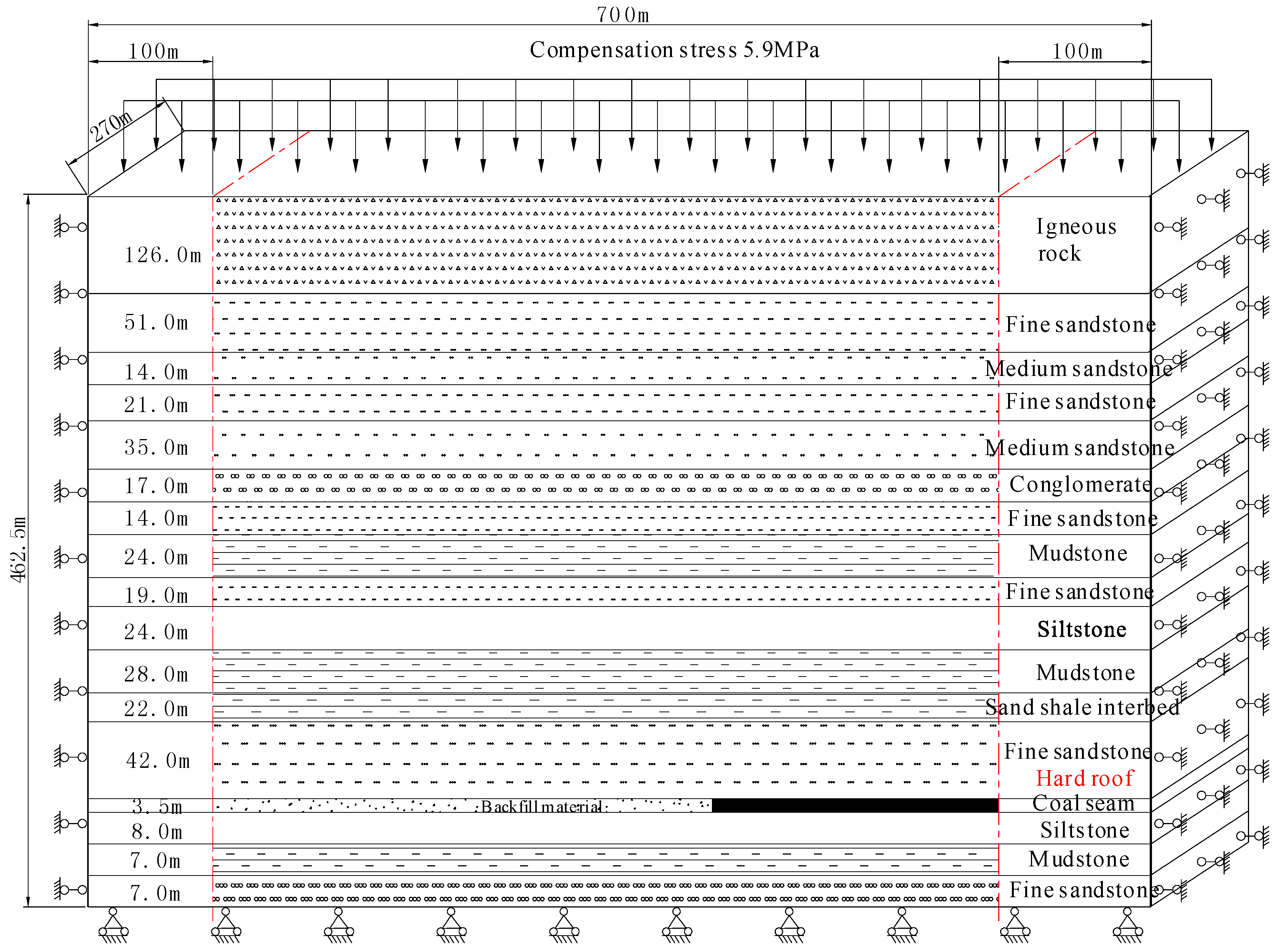
The SBCM technique can be used to control rock bursts induced by hard roofs. In order to study the effects of backfill ratios, the numerical model including the coal seam, hard roof, and backfill materials will be built. Based on the specific geological conditions around working panel 6304-1, FLAC3D software (Itasca, Minneapolis, MN, USA) [27,28] was used to establish a numerical model. FLAC3D is a three-dimensional explicit finite-difference program for engineering mechanics computation. It offers a wide range of capabilities to solve complex problems in mechanics, and especially in geomechanics. This software also contains a powerful built-in programming language, FISH, that enables the user to define new variables and functions. The model dimension is 700 m × 270 m × 462.5 m. To facilitate mesh generation, the thickness of the strata is set as an integer (inevitably an approximation) according to prevailing conditions. Furthermore, the meshes depicting those strata surrounding the coal seams are refined and the model was divided into 520,800 elements and 543,414 nodes. Moreover, 5.9 MPa of uniformly distributed pressure was applied to the upper boundary of the model to simulate the self-weight stress imposed by the overlying strata. The horizontal displacement was constrained on the side boundaries, and the horizontal and vertical displacements were constrained on the bottom boundary. In addition, a 100 m long coal pillar was left on each side boundary to eliminate the influences of boundary conditions on the excavation. The specific model is shown in Figure 4. A Mohr-Coulomb model was used to represent the coal rock masses and the backfill materials were simulated by using a non-linear compaction procedure compiled in the FISH language (See Section 3.3). The virgin stress on the model was simulated initially, followed by simulation of the excavation and backfill processes. In this way, the actual deformation of, and stress on the surrounding strata could be obtained.
3.2. Numerical Simulation Schemes
Before a hard roof fractures for the first time, significant abutment stress and strain energy are accumulated in the working panel. With the increase of the roof-controlled backfill ratio, the backfill materials directly affected the roof deformation, the stope stress distributions, and the energy distributions. Zhang et al. [3] studied the fracture distance of hard roofs with different roof-controlled backfill ratios. When the roof-controlled backfill ratio is less than 82.5%, the roof before fracturing, is not in contact with the backfill materials, so backfill does not influence fracturing in the roof and the fracture distance is 151.5 m in that case. While, at roof-controlled backfill ratios of no more than 93%, the roof is in contact with the backfill materials before being fractured. Therefore, the backfill is able to exert the control effects on the roof deformation before fracturing. With increasing roof-controlled backfill ratio, the fracture distance of the roof increases accordingly. When the roof-controlled backfill ratio reaches 93%, the fracture distance is 213.4 m. When the roof-controlled backfill ratio exceeds 93%, the backfill provides effective support to the roof, and deformation instead of fracture occurs. According to the above results, the roof-controlled backfill ratio has decisive impact on the control effects of hard roofs. However, when the roof-controlled backfill ratios are less than 82.5%, between 82.5% and 91% and more than 93%, respectively, the deformation behavior of hard roof has not been studied. Therefore, while analysing the advanced abutment stress and energy distributions under the conditions of different roof-controlled backfill ratios, the excavation distance of the model should approach the fracture distance of a hard roof. While the deformation of hard roofs is analysed, simulation is carried out supposing that the excavation of the working panel is complete. The specific simulation schemes are summarised in Table 2.
3.3. Simulation Method of Backfill Materials
(1) Compaction properties of the backfill materials.
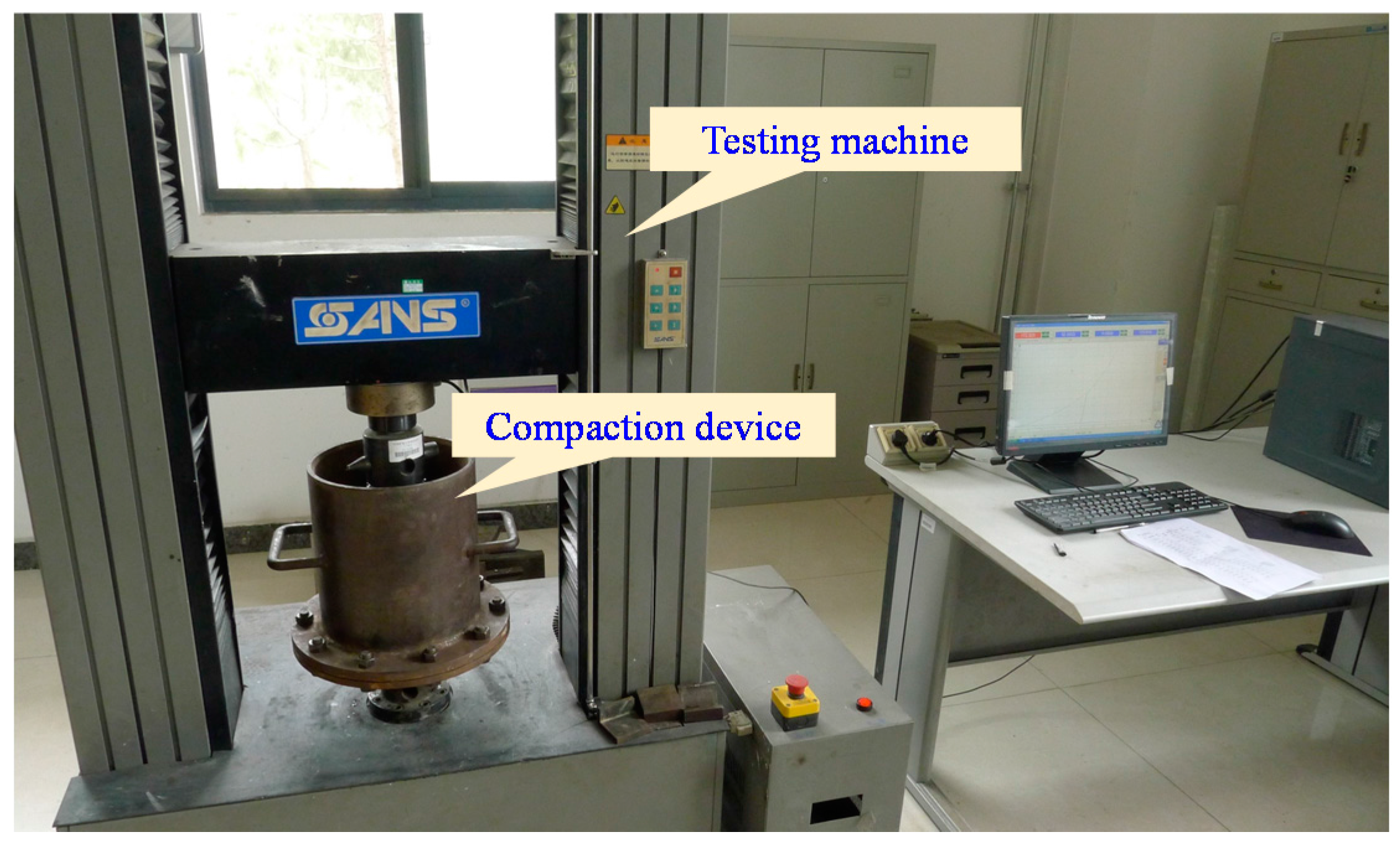
When backfill materials are filled into the goafs, they are gradually compressed and deformed under the effects of the weight of the overlying strata, so the compaction properties of the backfill materials have to be tested. As for backfill panel 6304-1, the crushed gangues were used to fill goafs. To test these materials, samples were collected from panel 6304-1 for preparation in the laboratory before testing their compaction properties. The test system incorporated a SANS testing machine and a self-built compaction device, as shown in Figure 5. The testing machine is equipped with data acquisition software, which can obtain mechanical data, such as load and displacement. The compaction device comprises a steel chamber, a base, a dowel bar, and a loading platen. The steel chamber measures 125 mm and 137 mm (inner and outer radii, respectively) and the chamber wall measures 305 mm and 12 mm (height and thickness, respectively). The steel chamber is connected with the base by flanges. In addition, the radius and height of the loading platen are 124 mm and 40 mm, respectively, which can allow imposition of a uniform stress on the sample under test.
Each test was carried out four times to simulate the compaction properties of backfill materials without being compacted, or under 1, 1.5, and 2 MPa applied compactive stress. Before compacting the backfill materials, a stress of 16.5 MPa was applied to the backfill material in the steel chamber to replicate the in situ at-rest stress on working panel 6304-1. When compacting the backfill materials, stress was applied to the gangues in the steel chamber, initially to the required compactive effort, before unloading to 0 MPa, followed by reloading to 16.5 MPa. By sorting the experimental data, the stress-strain curves of samples with different particle sizes were obtained (Figure 6). The stress-strain relationship for each group of samples showed non-linear, compaction-induced, deformation properties. Moreover, with increasing axial stress, the strain in each sample gradually increased, but the strain increment became smaller until the sample reached a stable state. Furthermore, strain hardening was observed in the samples. Based on the acquired experimental data, the axial strain-time curves of these samples under different stress states were drawn (see Figure 6).
(2) Simulation methods used for backfill materials.
Based on the compaction test used for backfill materials, as listed in Table 3, the stress σv on the gangue backfill materials followed an exponential relationship with strain εv:
where, a, b, and c are fitting parameters.
According to Equation (1), the compression modulus EM of the gangue backfill materials is obtained thus:
In the FLAC3D software, the elastic parameters consist of the bulk modulus K and shear modulus G, therefore, Equation (1) can be expressed as [29]:
Meanwhile, the relationships between bulk modulus K, shear modulus G and Poisson’s ratio μ can be expressed as:
By substituting Equation (4) into Equation (3), the vertical stress can be rewritten as:
where, μ is the Poisson’s ratio. Combining equations (2) and (5), the relationships between strain εv and K and G are obtained:
By using the in-built FISH language in FLAC3D, the non-linear compaction procedure is programmed accordingly. By monitoring the vertical strain in the backfill materials during their compaction, the bulk and shear moduli of the backfill materials were dynamically updated in each time step using Equation (6) until the calculation reached equilibrium. This method can simulate the compaction-induced deformation of an in situ backfill material under stress from the overlying strata. According to the stress-strain relationships in Figure 6, the backfill material parameters can be obtained. By using the non-linear compaction procedure and model parameters in Section 3.1, the model can be built and used to simulate different schemes.
3.4. Strain Energy Simulation
In accordance with the generalised form of Hooke’s law, the stress and strain obey the following relationship under spatially-varying stress states [30]:
where, σ1, σ2, and σ3 denote the three principal stresses, while ε1, ε2, and ε3 are the three principal strains. Moreover, E and u represent the elastic modulus and Poisson’s ratio of coal rock masses, respectively. The strain energy density in a spatially varying stress state is given by:
Substituting Equation (7) into Equation (8), the strain energy density in the coal rock mass is obtained:
In the FLAC3D software, the procedure for strain energy calculation is compiled in FISH [28], in accordance with Equation (9), thus giving the distribution of stope strain energies in SBCM.
4. Analysis of Simulation Results
4.1. Deformation of Hard Roofs
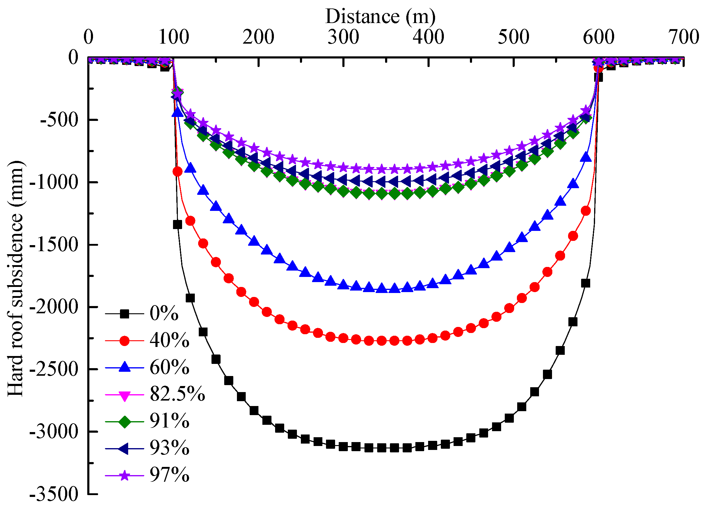
When the roof-controlled backfill ratios were 0, 40%, 60%, 82.5%, 91%, 93% and 97%, the maximum subsidence of the hard roofs after the working panels have been completely mined are shown in Figure 7.
It can be seen from Figure 7 that:
- (1)
- After mining the entire working panel, the maximum subsidence of the hard roof decreases with increasing roof-controlled backfill ratio. When the roof-controlled backfill ratios were 0%, 40%, 60%, 82.5%, 91%, 93% and 97%, the maximum subsidences of the roof were 3130, 2270, 1860, 1180, 1090, 996 and 898 mm, respectively. This indicated that the backfill materials did control the roof subsidence.
- (2)
- The lower the roof subsidence, the lower the gravitational potential energy released by roof deformation. Therefore, with the increase in the roof-controlled backfill ratio, rock bursts are less likely to occur.
4.2. Stope Stress Distributions
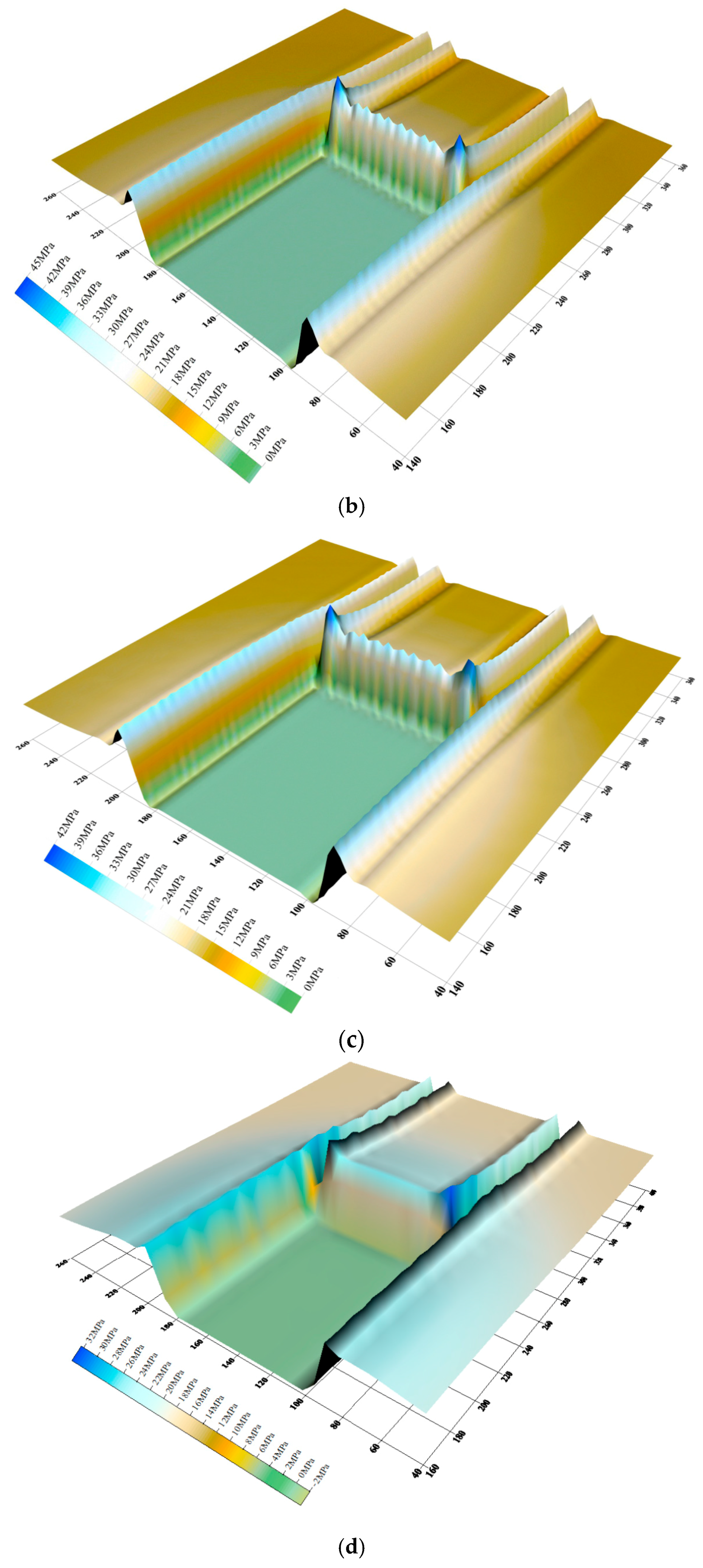
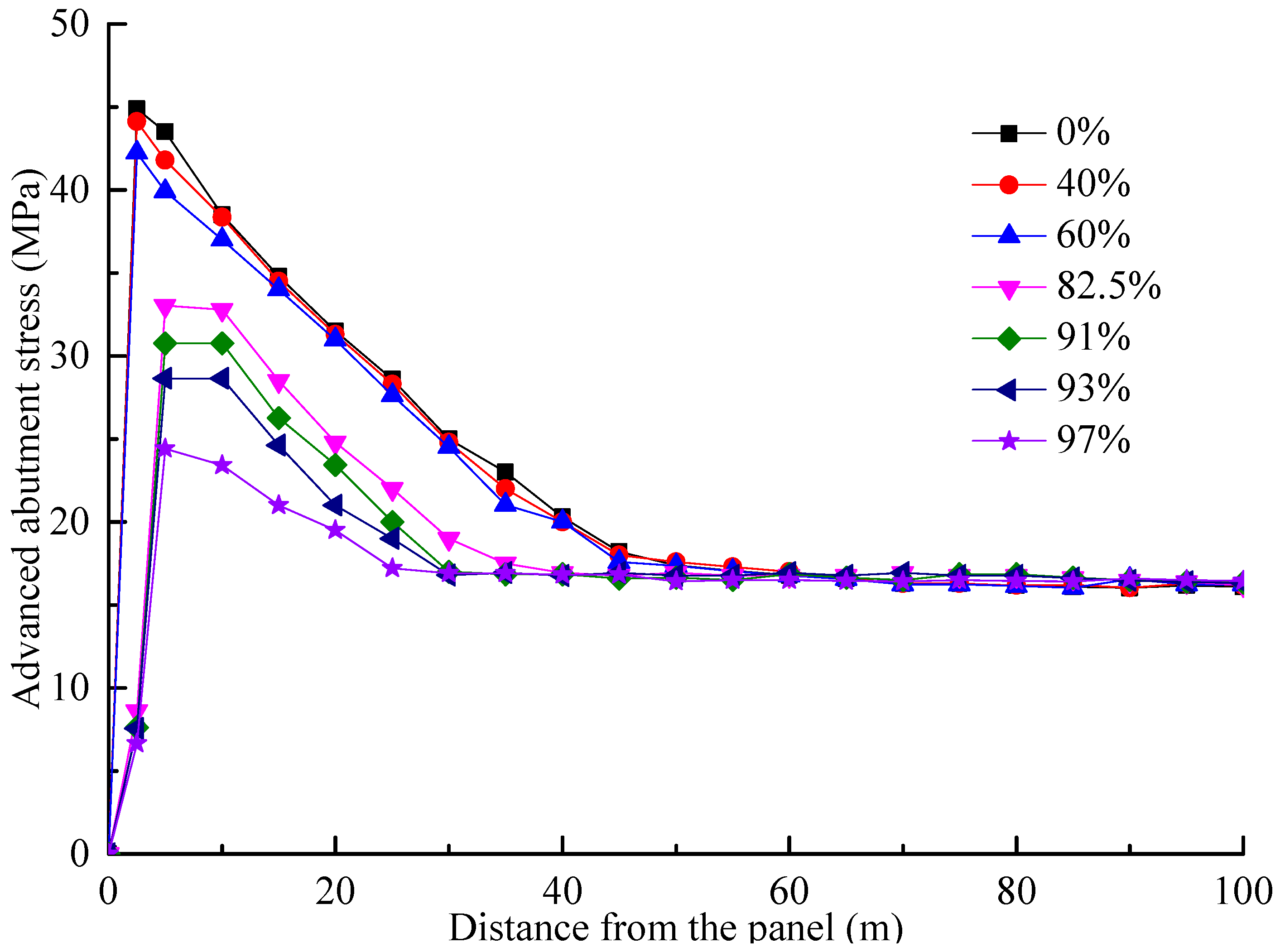
Before the fracture of a hard roof, the distribution of advanced abutment stress on the working panel with different roof-controlled backfill ratios are shown in Figure 8, with a comparison thereof in Figure 9.
As shown in Figure 8 and Figure 9, the distributions of the advanced abutment stresses in the backfill panel are similar to those in the mining panel found when using a caving method (i.e., when the roof-controlled backfill ratio is zero): along the direction of the working panels, an unloading zone, a pressure elevation zone, and an at-rest stress zone are shown:
- (1)
- Owing to the unloading zone being close to the coal walls of the working panels, the stress is lower than the at-rest stress.
- (2)
- With increasing distance from the panel, the advanced abutment stress increases significantly and reaches a maximum value at between 3 to 6 m from the coal walls and then decreases thereafter. Therefore, this zone is deemd to be a stress elevation zone and the stress in the coal seams is larger than the at-rest stress.
- (3)
- Far from the working panel, the coal seams are only slightly affected by the mining of the working panel, so this area was deemed to have been a zone of at-rest stresses.
- (4)
- The advanced abutment stresses are mainly concentrated within the 45 m in front of the working panel, in particular, the stress is highly concentrated on both sides of the roadways in this area (in a zone from 2 to 15 m deep).
Table 4 shows a comparison of distribution of advanced abutment stresses for different roof-controlled backfill ratios.
From Table 4 it may be deduced that:
- (1)
- When the roof-controlled backfill ratios are 40% and 60%, the peak value and range of influence of the advanced abutment stress on the working panel are the same with those found when using a caving mining method.
- (2)
- In the case of a varying roof-controlled backfill ratio (82.5%, 91%, 93% and 97%), the advanced abutment stresses on working panels decrease, along with their range of influence. When the ratio reaches 97%, the peak stress decreases from 44.9 MPa while using a mining caving method, to 24.4 MPa: the range of influence of the stresses decreases from 45 m to 25 m, which also significantly reduces the extent of stress concentration in front of the working panel.
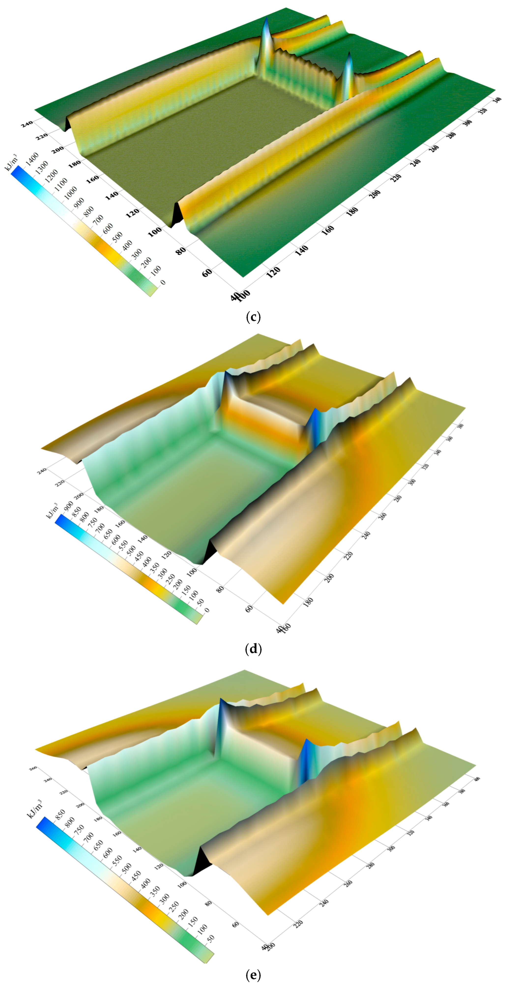
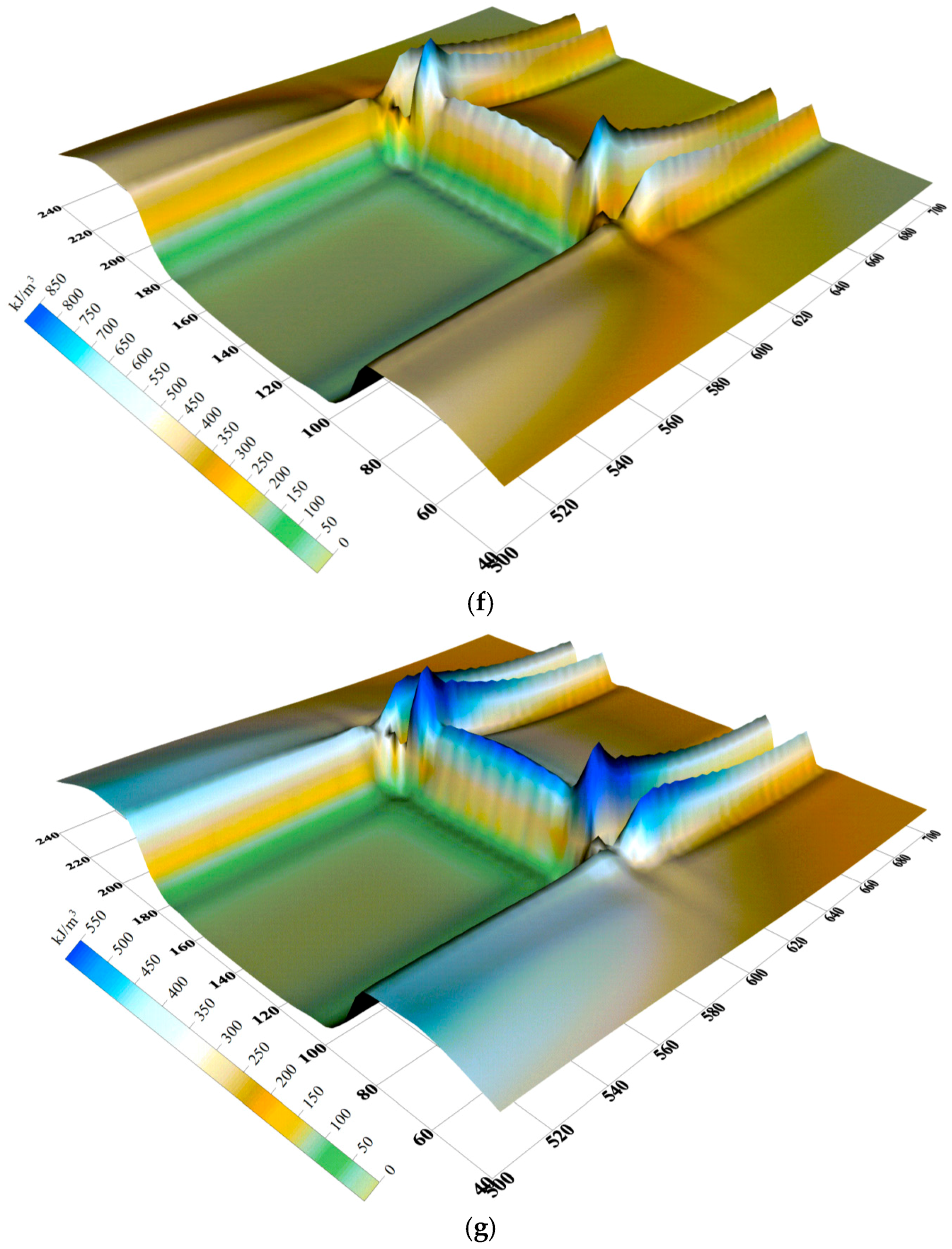
4.3. Strain Energy Distributions
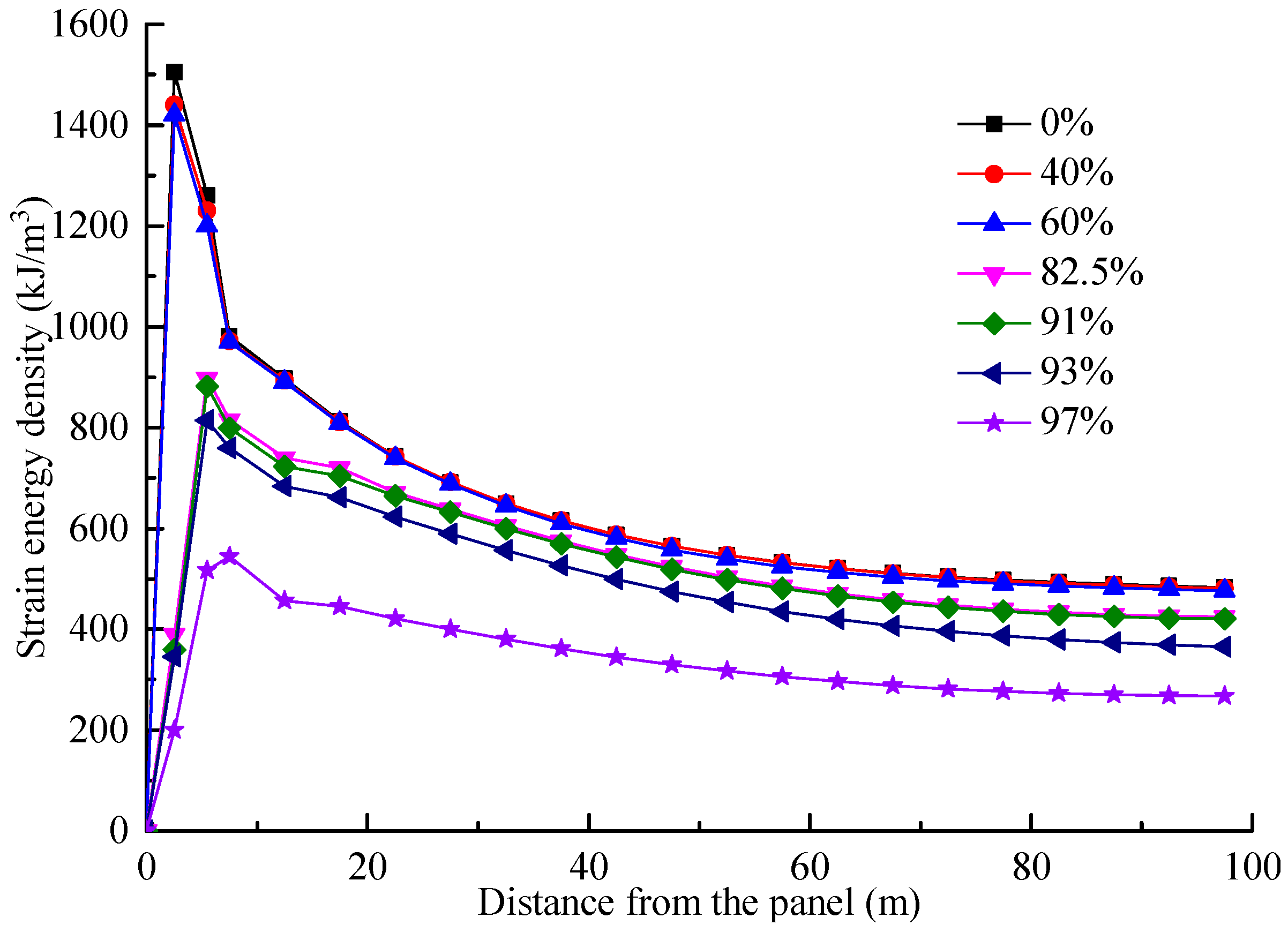
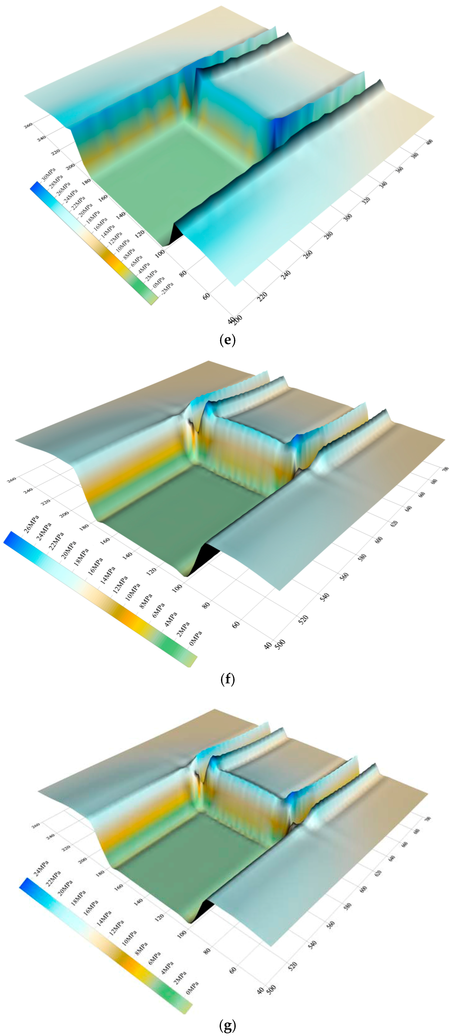
By substituting the three principal stress values arising from the numerical simulation into Formula (9), the distributions of stope strain energies in different roof-controlled backfill ratios are obtained, as shown in Figure 10 and Figure 11.
- (1)
- The distributions of strain energy in front of the working panel are similar to those of the stresses. When the caving method is used for mining, strain energy is concentrated within the first 45 m in front of the working panel and the maximum strain energy reaches 1545 kJ/m3.
- (2)
- When the roof-controlled backfill ratios are 40% and 60%, the backfill does not affect the energy distribution in front of the working panel, and the strain energy remains concentrated within 45 m of the front surface of the coal walls in the working panel. The maximum strain energies are 1440 kJ/m3 and 1420 kJ/m3, which are similar to those found when using the caving method.
- (3)
- When the roof-controlled backfill ratios are 82.5%, 91% and 93%, the strain energy in front of the working panel significantly decreases and the larger the roof-controlled backfill ratio, the more significant the decrease; however, when the roof-controlled backfill ratios are 91% and 93%, the strain energy in front of the working panel decreases slightly and the peak strain energies are 882 kJ/m3 and 814 kJ/m3, which are similar to that at a backfill ratio of 82.5%.
- (4)
- When the roof-controlled backfill ratio is 97%, the strain energy in front of the working panel rapidly decreases from its peak value of 544 kJ/m3. It decreases by 63.9% and 33.2%, separately, compared with those values found when using the caving method and with a roof-controlled backfill ratio of 93%.
From the above simulation results, when the roof-controlled backfill ratios are 40% and 60%, the backfill has no influence on the strain energy distributions in the rocks surrounding the stopes and the working panel are subject to the same dynamic hazards caused by energy accumulation as when using the caving method. If the roof-controlled backfill ratios are 82.5%, 91% and 93%, the presence of the backfill reduces the strain energy in front of the working panel, which can control the dynamic hazards resulting from energy accumulation. However, the increase of roof-controlled backfill ratio only slightly influences the preventative effect under these conditions. When the roof-controlled backfill ratio reaches 97%, the strain energy decreases significantly and the dynamic hazards are effectively prevented.
5. Conclusions
- (1)
- Based on the stress-strain relationship for the backfill materials, as obtained experimentally, the non-linear compaction procedure thereof is compiled by using the built-in FISH language in the FLAC3D software. This procedure can simulate the non-linear deformation of backfill materials under the stresses imposed by overlying strata, and can thus analyse the mining process as applied to the backfill panels studied here.
- (2)
- As the roof-controlled backfill ratio increases from 0 to 40% and 60%, only the release of gravitational potential energy in the goafs decreases: this has little effect on the distribution of the advanced abutment stress and strain energy density in the working panel. If the roof-controlled backfill ratios are 82.5%, 91% and 93%, the release of gravitational potential energy, the advanced abutment stress, and the strain energy density in goafs decrease significantly; however, the increase in the roof-controlled backfill ratio at this stage exerts only a slight influence on the reduction. When the roof-controlled backfill ratio reaches 97%, the advanced abutment stress and the strain energy density decrease. The maximum stress concentration factor is only 1.5 and the maximum strain energy density is 544 kJ/m3, decreased of 45.7% and 63.9%, separately, compared with those when the caving method is used.
- (3)
- When the roof-controlled backfill ratios are 40% and 60%, the backfill could only reduce the release of gravitational potential energy, but has no influence on the distribution of the strain energy density in the stopes. This reduces the risk of occurrence of a rock burst arising from the release of gravitational potential energy, however, the dynamic hazards caused by strain energy accumulation and release have little difference to those found when using the caving method. When the roof-controlled backfill ratios are 82.5%, 91% and 93%, the backfill reduces the stope stresses and the strain energy density, which decreases the risk of a rock burst, but the increase in roof-controlled backfill ratio does also slightly influence the preventative effects at this stage. When the roof-controlled backfill ratio further increases to 97%, the stope stresses, release of gravitational potential energy, and strain energy density largely decrease, showing significant rock burst preventative effects.
- (4)
- The rock burst induced by hard roofs will pose a serious threat to the safety of staff and equipment in coal mining. The SBCM technique can be effectively used to solve the problem of rock bursts induced by hard roofs. However, when the backfill materials are filled into the coal mine goaf, the different backfill ratios will lead to quite different control effects. If the backfill ratio is lower, the rock burst will not be controlled. On the contrary, too high backfill ratios will be certain to add to the production costs. Therefore, the control effects including deformation, stress, and energy, of hard roofs in different backfill ratios are studied in this paper. The research results can provide reference to other coal mines with the similar geological conditions.
Acknowledgments
This research was supported by National Natural Science Foundation of China (51504238) and the Foundation for Distinguished Professors of Jiangsu Province (2015-29).
Author Contributions
All the authors contributed to this paper. Meng Li prepared and edited the manuscript. Ji-Xiong Zhang provided theoretical and methodological guidance in the research process. Nan Zhou partially participated in literature search and data processing. Zhicheng Liu participated in revising the manuscript.
Conflicts of Interest
The authors declare no conflict of interest.
References
- Zheng, Z.T.; Xu, Y.; Li, D.S.; Dong, J.H. Numerical analysis and experimental study of hard roofs in fully mechanized mining faces under sleeve fracturing. Minerals 2015, 5, 758–777. [Google Scholar] [CrossRef]
- Wang, W.; Cheng, Y.P.; Wang, H.F.; Liu, H.Y.; Wang, L.; Li, W.; Jiang, J.Y. Fracture failure analysis of hard–thick sandstone roof and its controlling effect on gas emission in underground ultra-thick coal extraction. Eng. Fail. Anal. 2015, 54, 150–162. [Google Scholar] [CrossRef]
- Zhang, J.X.; Li, B.Y.; Zhou, N.; Zhang, Q. Application of solid backfilling to reduce hard-roof caving and longwall coal face burst potential. Int. J. Rock Mech. Min. Sci. 2016, 88, 197–205. [Google Scholar] [CrossRef]
- Rennia, B.K.; Brian, A. Prediction of rock brittleness using nondestructive methods for hard rock tunneling. J. Rock Mech. Geotech. Eng. 2016, 8, 533–540. [Google Scholar]
- Wang, P.; Jiang, J.Q.; Zhang, P.P.; Wu, Q.L. Breaking process and mining stress evolution characteristics of a high-position hard and thick stratum. Int. J. Min. Sci. Technol. 2016, 26, 563–569. [Google Scholar] [CrossRef]
- Zhang, Y.; Cao, S.G.; Lan, L.X.; Gao, R.; Yan, H. Analysis of Development Pattern of a Water-Flowing Fissure Zone in Shortwall Block Mining. Energies 2017, 10, 734. [Google Scholar] [CrossRef]
- Mangal, A.; Paul, P.S. Rock mechanical investigation of strata loading characteristics to assess caving and requirement of support resistance in a mechanized powered support longwall face. Int. J. Min. Sci. Technol. 2016, 26, 1081–1087. [Google Scholar] [CrossRef]
- Tao, X.; Yang, T.H.; Chen, C.F.; Liu, H.L.; Yu, Q.L. Mining induced strata movement and roof behavior in underground coal mine. Geomech. Geophys. Geo-Energy Geo-Resour. 2015, 1, 79–89. [Google Scholar]
- Rahul; Khandelwal, M.; Rai, R.; Shrivastva, B.K. Evaluation of dump slope stability of a coal mine using artificial neural network. Geomech. Geophys. Geo-Energy Geo-Resour. 2015, 1, 69–77. [Google Scholar]
- Xue, Y.; Gao, F.; Teng, T.; Xing, Y. Effect of Gas Pressure on Rock Burst Proneness Indexes and Energy Dissipation of Coal Samples. Geotech. Geol. Eng. 2016, 34, 1737–1748. [Google Scholar] [CrossRef]
- Hamdi, J.; Souley, M.; Scholtes, L.; Heib, M.A.; Gunzburger, Y. Assessment of the Energy Balance of Rock Masses through Discrete Element Modelling. Procedia Eng. 2017, 191, 442–450. [Google Scholar] [CrossRef]
- Wang, J.C.; Jiang, F.X.; Meng, X.J.; Wang, X.Y.; Zhu, S.T.; Feng, Y. Mechanism of rock burst occurrence in specially thick coal seam with rock parting. Rock Mech. Rock Eng. 2016, 49, 1953–1965. [Google Scholar] [CrossRef]
- Lawson, H.E.; Tesarik, D.; Larson, M.K.; Abraham, H. Effects of overburden characteristics on dynamic failure in underground coal mining. Int. J. Min. Sci. Technol. 2017, 27, 121–129. [Google Scholar] [CrossRef]
- Christopher, M. Coal bursts in the deep longwall mines of the United States. Int. J. Coal Sci. Technol. 2016, 3, 1–9. [Google Scholar]
- Mu, Z.L.; Dou, L.M.; Zhang, G.W.; Zhang, S.B.; Li, Z.H.; Zhang, J. Study of prevention methods of rock burst disaster caused by hard rock roof. J. China Univ. Min. Technol. 2006, 35, 737–741. [Google Scholar]
- Guo, W.J.; Li, Y.Y.; Yin, D.W.; Zhang, S.C. Mechanisms of rock burst in hard and thick upper strata and rock-burst controlling technology. Arab. J. Geosci. 2016, 9, 1–11. [Google Scholar] [CrossRef]
- Zubelewicz, A.; Mróz, Z. Numerical simulation of rock burst processes treated as problems of dynamic instability. Rock Mech. Rock Eng. 1983, 16, 253–274. [Google Scholar] [CrossRef]
- Goszcz, A. Roof rock bursts and ways to combat them. Arch. Min. Sci. 1991, 36, 239–261. [Google Scholar]
- Dou, L.M.; Lu, C.P.; Mu, Z.L.; Gao, M.S. Prevention and forecasting of rock burst hazards in coal mines. Min. Sci. Technol. 2009, 19, 585–591. [Google Scholar] [CrossRef]
- Hirata, A.; Kameoka, Y.; Hirano, T. Safety Management Based on Detection of Possible Rock Bursts by AE Monitoring during Tunnel Excavation. Rock Mech. Rock Eng. 2007, 40, 563–576. [Google Scholar] [CrossRef]
- Zhang, J.X.; Jiang, H.Q.; Deng, X.J.; Ju, F. Prediction of the height of the water-conducting zone above the mined panel in solid backfill mining. Mine Water Environ. 2014, 33, 317–326. [Google Scholar] [CrossRef]
- Junker, M.; Witthaus, H. Progress in the research and application of coal mining with stowing. Int. J. Min. Sci. Technol. 2013, 23, 7–12. [Google Scholar] [CrossRef]
- Li, H.Z.; Zha, J.F.; Guo, G.L.; Zhao, B.C.; Wang, B. Compression ratio design and research on lower coal seams in solid backfilling mining under urban areas. Soil Mech. Found. Eng. 2016, 53, 125–131. [Google Scholar]
- Li, M.; Zhang, J.X.; Deng, X.J.; Ju, F.; Li, B.Y. Measurement and numerical analysis of water-conducting fractured zone in solid backfill mining under an aquifer: A case study in China. Q. J. Eng. Geol. Hydrogeol. 2017, 50, 81–87. [Google Scholar] [CrossRef]
- Zhang, J.X.; Zhang, Q.; Sun, Q.; Gao, R.; Germain, D.; Abro, S. Surface subsidence control theory and application to backfill coal mining technology. Environ. Earth Sci. 2015, 74, 1439–1448. [Google Scholar] [CrossRef]
- Ju, F.; Li, B.Y.; Guo, S.; Xiao, M. Dynamic characteristics of gangues during vertical feeding in solidbackfill mining: A case study of the Wugou coal mine in China. Environ. Earth Sci. 2016, 75, 1389–1397. [Google Scholar] [CrossRef]
- Sinha, S.; Chugh, P. An evaluation of roof support plans at two coal mines in Illinois using numerical models. Int. J. Rock Mech. Min. Sci. 2016, 82, 1–9. [Google Scholar] [CrossRef]
- Itasca. Fast Lagrangian Analysis of Continua in 3 Dimension; Version 3.1; User’s Guide: Minneapolis, MN, USA, 2007. [Google Scholar]
- Bai, Q.S.; Tu, S.H.; Chen, M.; Zhang, C. Numerical modeling of coal wall spall in a longwall face. Int. J. Rock Mech. Min. Sci. 2016, 88, 242–253. [Google Scholar] [CrossRef]
- Timoshenko, S.; Goodier, J.N. Theory of Elasticity, 3rd ed.; McGraw Hill: New York, NY, USA, 1970. [Google Scholar]
Figure 1.
Schematic diagram of the SBCM technique.
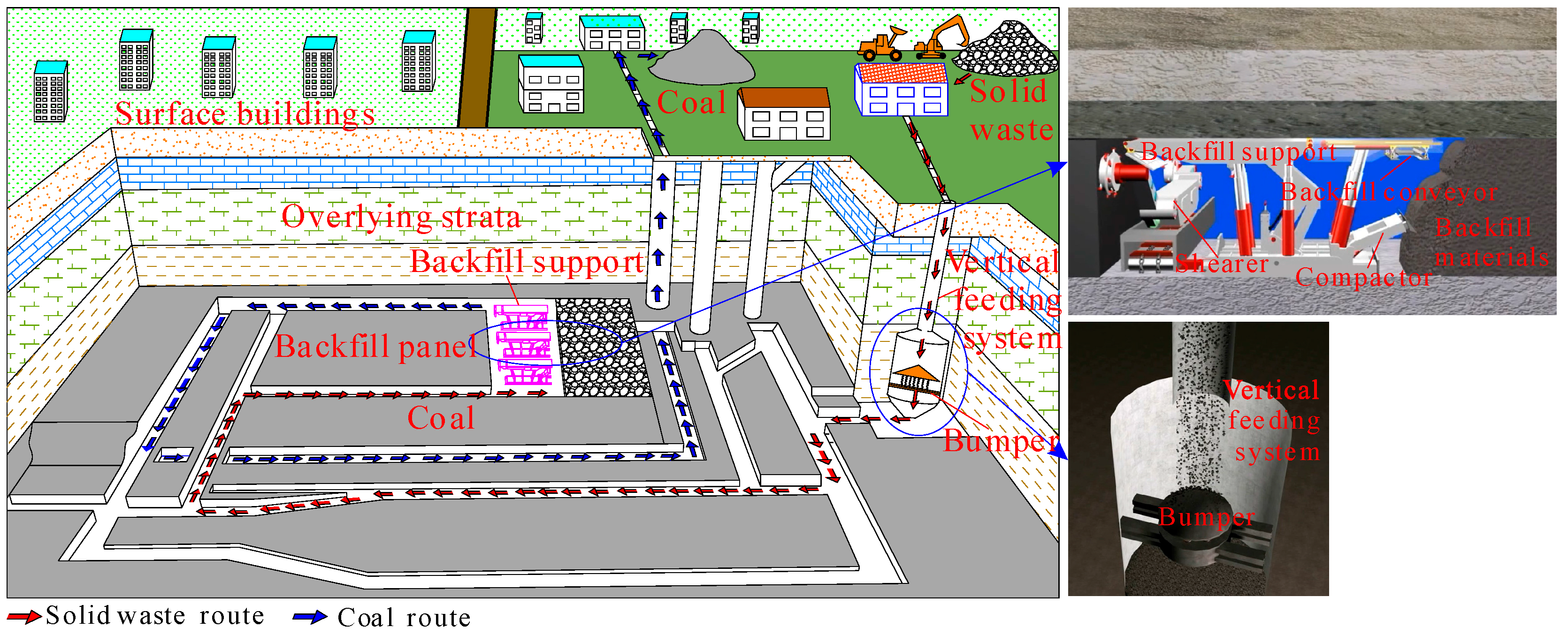
Figure 2.
Photographs for underground backfill: (a) backfill support; (b) backfill conveyor; and (c) no gap with roof.
Figure 2.
Photographs for underground backfill: (a) backfill support; (b) backfill conveyor; and (c) no gap with roof.
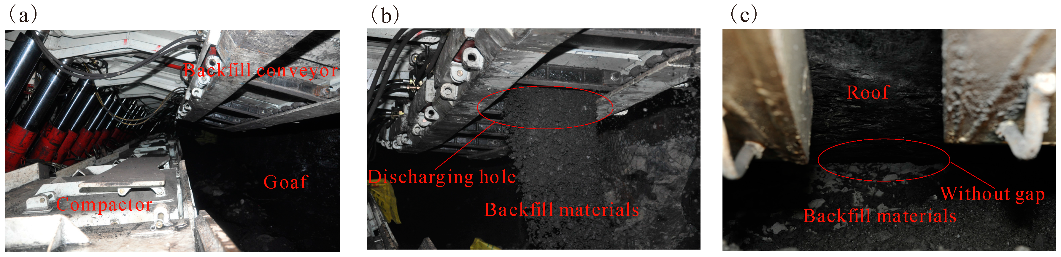
Figure 3.
Position of the coal mine and layout of the 6304 working panel.

Figure 4.
The numerical analysis model and basic parameters.

Figure 5.
The testing machine and a self-built compaction device.

Figure 6.
Stress-strain curves for backfill materials.
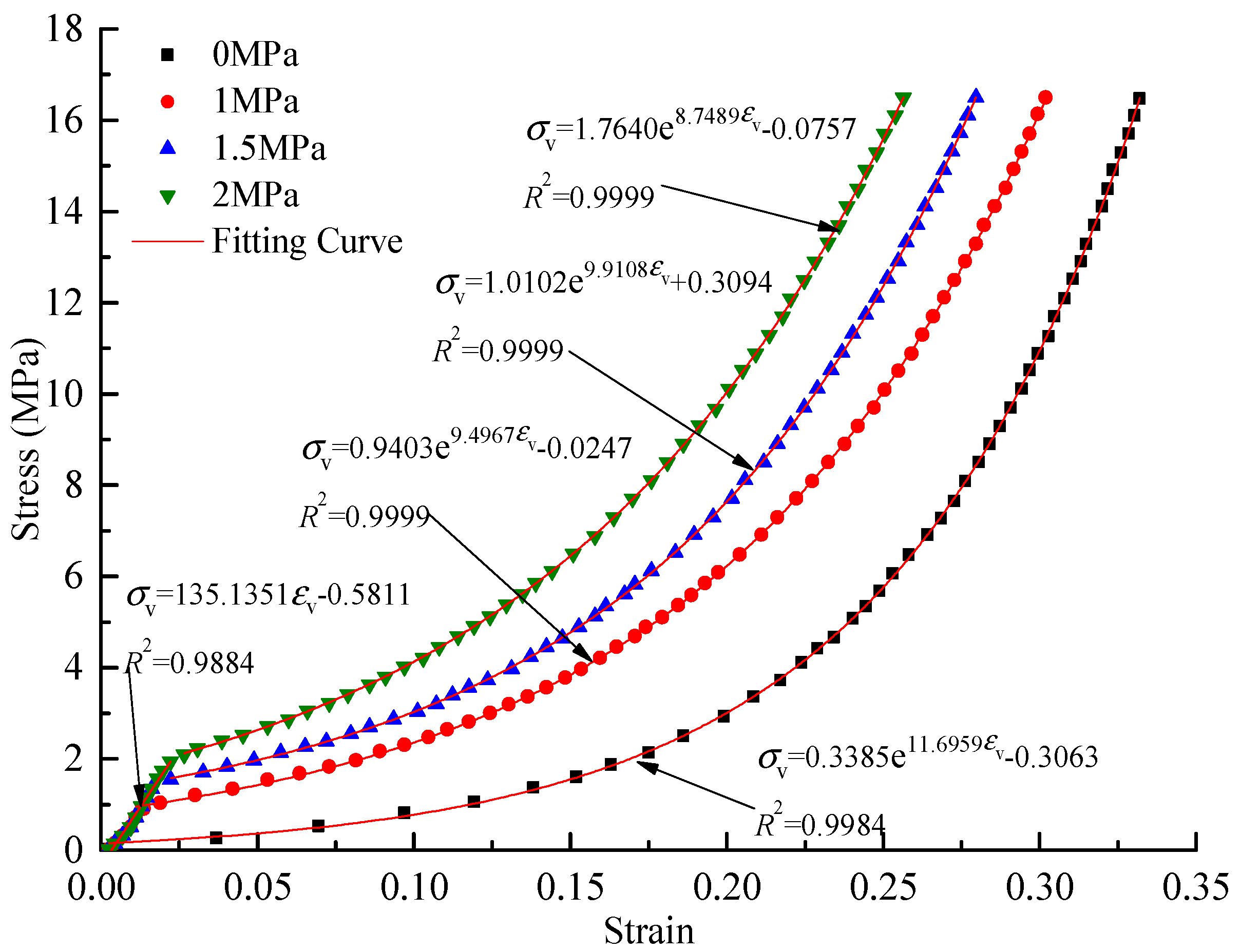
Figure 7.
Maximum subsidence of the hard roof for different roof-controlled backfill ratios.

Figure 8.
Distributions of advanced abutment stress for different roof-controlled backfill ratios: (a) 0%; (b) 40%; (c) 60%; (d) 82.5%; (e) 91%; (f) 93%; and (g) 97%.
Figure 8.
Distributions of advanced abutment stress for different roof-controlled backfill ratios: (a) 0%; (b) 40%; (c) 60%; (d) 82.5%; (e) 91%; (f) 93%; and (g) 97%.
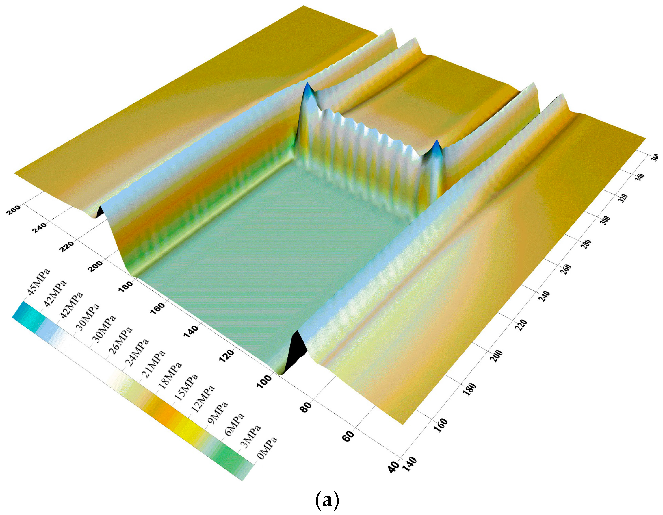


Figure 9.
Comparative analysis of advanced abutment stress for different roof-controlled backfill ratios.
Figure 9.
Comparative analysis of advanced abutment stress for different roof-controlled backfill ratios.

Figure 10.
Strain energy distributions for different roof-controlled backfill ratios: (a) 0%; (b) 40%; (c) 60%; (d) 82.5%; (e) 91%; (f) 93%; and (g) 97%.
Figure 10.
Strain energy distributions for different roof-controlled backfill ratios: (a) 0%; (b) 40%; (c) 60%; (d) 82.5%; (e) 91%; (f) 93%; and (g) 97%.
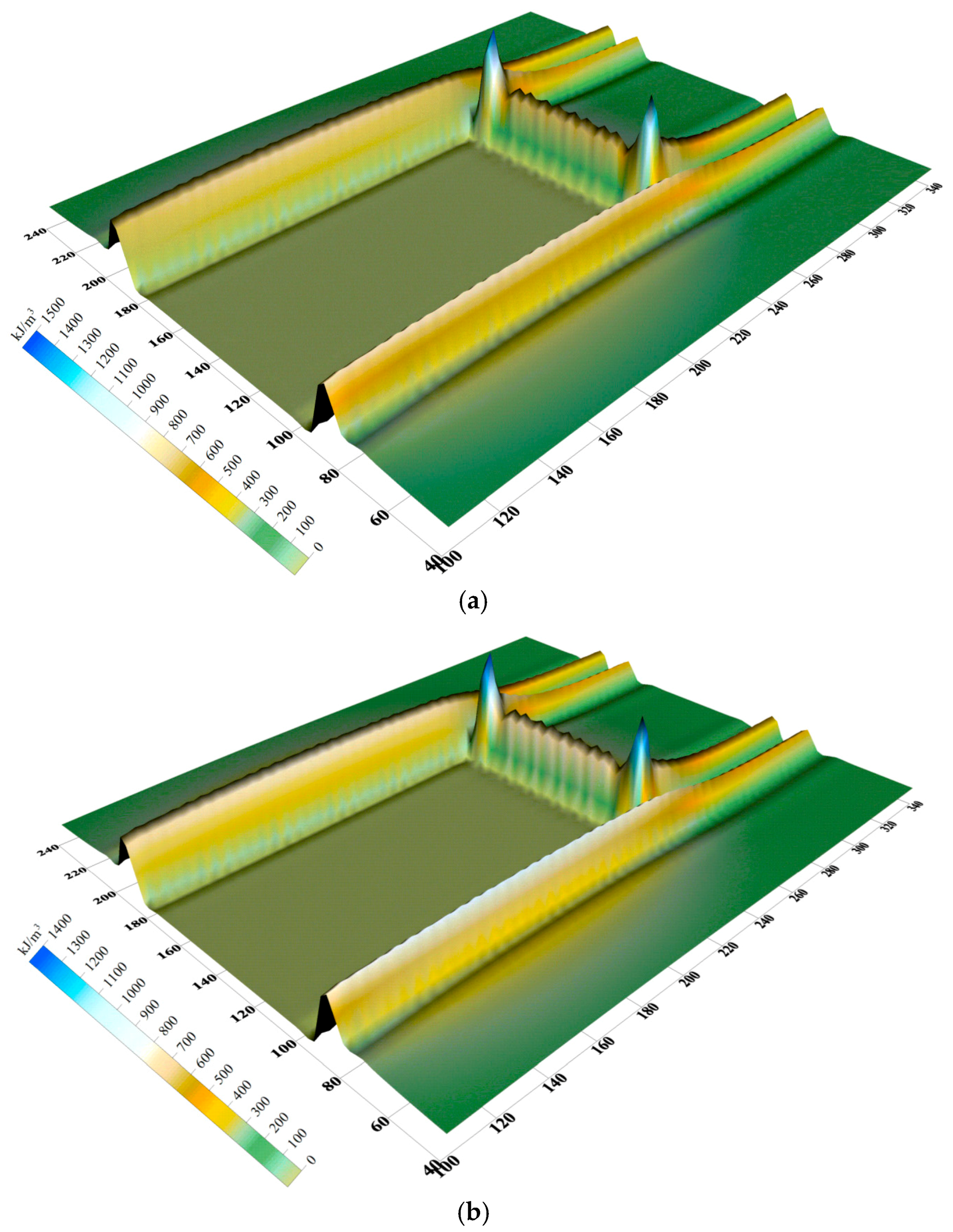


Figure 11.
Comparative analysis of strain energy for different roof-controlled backfill ratios.

Table 1.
The details of roofs and floors in the No. 3 coal seam.
| Mine Area | Rock Category | Thickness (m) | Rock Features |
|---|---|---|---|
| Main roof | Fine- and medium-grained sandstone | 32.5~49.75 41.63 | The rock is grey-white in colour and consists of a lot of quartz, and feldspar with a small amount of dark, green minerals: f = 8~10. |
| Immediate roof | Mudstone | 0.0~1.02 | The rock is brown-grey in colour and contains many plant root fossils: f = 2~3. |
| Immediate floor | Aluminous mudstone | 0.0~3.20 | The rock is light grey in colour and smooth textured, and it contains plant fossil fragments: f = 2~3. |
| Main floor | Fine-grained sandstone | 2.7~8.43 5.85 | The rock is light to dark-grey in colour, and is dense and hard: f = 6~8. |
Table 2.
Simulation schemes in different backfill ratios.
| Group | Roof-Controlled Backfill Ratio (%) | Backfill Height (m) | Initial Applied Stress (MPa) | Mining Distance (m) |
|---|---|---|---|---|
| 1 | 0 | 0 | 0 | 150 |
| 2 | 40 | 1.75 | 0 | 150 |
| 3 | 60 | 2.50 | 0 | 150 |
| 4 | 82.5 | 3.50 | 0 | 170 |
| 5 | 91 | 3.50 | 1.0 | 195 |
| 6 | 93 | 3.50 | 1.5 | 500 |
| 7 | 97 | 3.50 | 2.0 | 500 |
Table 3.
Stress-strain relationships under different backfill ratios.
| Group | Roof-Controlled Backfill Ratio (%) | Initial Applied Stress (MPa) | Stress-Strain Relationship |
|---|---|---|---|
| 1 to 4 | 0, 40, 60, and 82.5 | 0 | |
| 5 | 91 | 1.0 | (0 ≤ σv < 1.0) |
| (1.0 ≤ σv) | |||
| 6 | 93 | 1.5 | (0 ≤ σv < 1.5) |
| (1.5 ≤ σv) | |||
| 7 | 97 | 2.0 | (0 ≤ σv < 2.0) |
| (2.0 ≤ σv) |
Table 4.
Comparison of distribution of advanced abutment stress.
| Roof-Controlled Backfill Ratio (%) | Backfill Height (m) | Initial Applied Stress (MPa) | Advanced Abutment Stress (MPa) | Distance between Stress Peak and Coal Rib (m) | Stress Concentration Factor | Influence Distance (m) |
|---|---|---|---|---|---|---|
| 0 | 0 | 0 | 44.9 | 3.0 | 2.7 | 45.0 |
| 40% | 1.75 | 0 | 44.1 | 3.0 | 2.7 | 45.0 |
| 60% | 2.50 | 0 | 42.3 | 3.0 | 2.6 | 45.0 |
| 82.5% | 3.50 | 0 | 33.0 | 6.0 | 2.0 | 35.0 |
| 91% | 3.50 | 1.0 | 30.8 | 6.0 | 1.9 | 30.0 |
| 93% | 3.50 | 1.5 | 28.6 | 6.0 | 1.7 | 30.0 |
| 97% | 3.50 | 2.0 | 24.4 | 6.0 | 1.5 | 25.0 |
© 2017 by the authors. Licensee MDPI, Basel, Switzerland. This article is an open access article distributed under the terms and conditions of the Creative Commons Attribution (CC BY) license (http://creativecommons.org/licenses/by/4.0/).
Share and Cite
MDPI and ACS Style
Li, M.; Zhou, N.; Zhang, J.; Liu, Z. Numerical Modelling of Mechanical Behavior of Coal Mining Hard Roofs in Different Backfill Ratios: A Case Study. Energies 2017, 10, 1005. https://doi.org/10.3390/en10071005
AMA Style
Li M, Zhou N, Zhang J, Liu Z. Numerical Modelling of Mechanical Behavior of Coal Mining Hard Roofs in Different Backfill Ratios: A Case Study. Energies. 2017; 10(7):1005. https://doi.org/10.3390/en10071005
Chicago/Turabian StyleLi, Meng, Nan Zhou, Jixiong Zhang, and Zhicheng Liu. 2017. "Numerical Modelling of Mechanical Behavior of Coal Mining Hard Roofs in Different Backfill Ratios: A Case Study" Energies 10, no. 7: 1005. https://doi.org/10.3390/en10071005
Note that from the first issue of 2016, this journal uses article numbers instead of page numbers. See further details here.