
Multi-Frequency Control in a Stand-Alone Multi-Microgrid System Using a Back-To-Back Converter


Department of Electrical Engineering, Incheon National University, Songdo-dong, 119 Academy-ro, Yeonsu-gu, Incheon 22012, Korea
*
Author to whom correspondence should be addressed.
Energies 2017, 10(6), 822; https://doi.org/10.3390/en10060822
Submission received: 4 May 2017
/
Revised: 7 June 2017
/
Accepted: 13 June 2017
/
Published: 17 June 2017
(This article belongs to the Special Issue Advanced Operation and Control of Smart Microgrids)
Abstract
:A stand-alone multi-microgrid (MMG) system can be formed by connecting multiple stand-alone microgrids (MGs). In the stand-alone MMG system where the frequencies of each MG system are different, a back-to-back (BTB) converter can be used for interconnecting the adjacent MG system. The frequency control performance of the MMG system can be improved by designing the suitable controller of the BTB converter. This study proposes a multi-frequency control in the BTB converter to improve the performance of frequency regulation in the MMG system. Autonomous power sharing between each MG system is achieved by using the proposed multi-frequency control. The stand-alone MMG system where two stand-alone MG systems with different nominal frequencies are interconnected using the BTB converter is simulated in this study to show the feasibility of the proposed multi-frequency controller. Each stand-alone MG system consists of an inverter-based distributed generator (DG) that uses a grid-forming converter with a conventional frequency droop controller. The inverter-based DG is responsible for the primary frequency control in each MG system. To show the effectiveness of the proposed multi-frequency control, a comparison study of the multi-frequency control and the single frequency control is presented in this study. Simulation results show that the system stability can be improved by using the proposed multi-frequency controller.
1. Introduction
A stand-alone multi-microgrid (MMG) system where several microgrids (MGs) are interconnected has gained more attention recently [1,2,3,4,5]. Interconnecting multiple stand-alone MG systems can bring the economic benefit due to the ability of sharing surplus power in each MG. Improving the system reliability is another advantage of the MMG system because the amount of load-shedding could be reduced, as mentioned in [6,7]. Moreover, the integration of renewable energy resources (RESs) into the MG system can be increased due to the flexible frequency qualities in the MMG system [8].
Generally, the connection of multiple stand-alone MGs in the MMG system can be classified into two types: by the AC line with the use of a breaker [9,10,11,12,13,14,15] or by the DC line with the use of the back-to-back (BTB) converters [16,17,18,19]. Connecting multiple MGs by the breaker or static switch with an appropriate synchronization algorithm can bring the advantage of the investment costs, however, managing power sharing between each MG might be difficult. Such topology is suitable for the multiple MG systems where the system frequency and voltage of all MGs are the same. Besides, the use of the BTB converter for interconnecting multiple MGs can easily manage the power sharing between multiple MGs. The system frequency and voltage of each MG can be controlled independently, which can provide the flexible frequency and voltage in the MMG system [8,16,17]. The flexible frequency operation strategy of the MMG system that considers different frequency qualities has been presented in [8] to enhance the penetration of RESs. The Ross Island project has built a physical dual frequency (50 Hz and 60 Hz) interlinked system by using a microgrid control distributed system [20]. Several researchers have proposed the use of BTB converters for connecting MG systems with the utility grid, in which the bidirectional power flow between the MG system and the grid can be easily regulated [21,22,23,24]. The topology of the hybrid MG system with DC connection at the BTB converter presented in [22] could bring the benefit of multiple AC and DC MGs integration at a common point. The use of the BTB converter can not only improve the power quality [23], but also limit the fault current in the MG system [24]. Interconnected multiple MG systems can support each other during contingencies by using the modified angle droop control strategy for the BTB converter [25].
The development of the MMG system poses some new challenges of coordination control between each MG system. Several MMG system control strategies have been presented to improve the frequencies in the MMG system. In [8], a distributed control strategy to control the power sharing among multiple stand-alone MGs has been proposed. Intertied microgrids, in which the adjacent MGs are connected by the BTB converters, has been discussed in [16,17] to achieve flexible frequency and voltage. An autonomous droop scheme proposed in [16,17] for intertied microgrids can achieve reserve sharing between overloaded and under-loaded microgrids. A droop frequency control scheme has been proposed in [26] to provide dynamic frequency support of the MMG system. The proposed control schemes in [16,17,26] are based on the fluctuation of the DC-link voltage of the BTB converter to improve the frequency of each MG system. However, the coupling of the frequency control and the dc-link voltage regulation in these control schemes might have a negative impact on the converter stability because the dc-link voltage of the BTB converter is oscillated by the disturbance in each MG system. Several control strategies of the DC-link voltage have been proposed for the BTB converters to improve the stability of the MMG system as well as the stability of the BTB converter [27,28,29]. The interface between multiple MGs based on the BTB converters has been discussed in [7,8,19] to enhance system stability since each MG can participate in the voltage and frequency regulation. Distribution-interline power flow controller has been used for interconnecting multiple MGs to manage the power sharing and optimally coordinate the adjacent MGs [18]. The frequency control algorithm of two connected MG systems has been presented in [30] to achieve the maximum collaboration between two MG systems with the minimum changes in the micro-sources power output. The hierarchical MMG system proposed in [31] is used to improve the frequency control performance in the transition mode.
In the stand-alone MMG system, regulating the system frequency in the acceptable deviation range plays an important role. The control system of the MMG system should be designed properly to ensure the system stability. Several frequency control strategies have been presented in previous works. However, these previous works mainly focused on the regulation of single frequency in the MMG system or design of the frequency management systems with complex algorithms like in [16,17,29,30]. The contribution of this study is to propose a multi-frequency control strategy in the MMG system. Compared to the frequency management systems in [16,17,29,30], the proposed multi-frequency control strategy is a simpler approach for regulating multiple frequencies in the MMG system. The proposed control strategy does not require any communication system, thus making it easy to extend the MMG system with the proposed multi-frequency control strategy. The system stability of the MMG system can be improved when the multi-frequency control is used in the BTB converter and power sharing between each MG system can be achieved autonomously by using the proposed multi-frequency control.
The tested MMG system considered in this study consists of two MG systems with different nominal frequencies (50 Hz and 60 Hz). It is assumed that the rated voltages of two the MGs are equal to 380 V. Although the rated voltages of two MGs are supposed to be the same, different values can be set for each MG without affecting the proper functioning of the proposed multi-frequency control. The BTB converter with the proposed multi-frequency control is used to interlink the two MGs. In each MG system, an inverter-based distributed generation (DG) with a conventional frequency droop control scheme is used as the main power supply. The feasibility of the proposed multi-frequency control is evaluated by testing the MMG system under different load change scenarios. To show the effectiveness of the multi-frequency control, the performance of the proposed multi-frequency control is compared to the single frequency control scheme.
The remaining of this study is arranged as follows: the inverter-based distributed generation in the stand-alone MG system is described in Section 2. Section 3 presents the architecture of the stand-alone MMG system with the BTB converter and the proposed multi-frequency control. The parameters of the tested MMG system and the simulation results are discussed in Section 4. The main conclusions are shown in Section 5.
2. Inverter-Based Distributed Generation
Recently, the use of the inverter-based DGs is becoming popular in MG systems. Compared to a conventional MG system using a synchronous generator such as a diesel generator, an MG system with inverter-based DGs has low inertia time constant value. The controller of the inverter-based DGs should be designed properly to ensure the system stability. Generally, DG power converters can be classified into three types: grid-feeding, grid-forming, and grid-supporting converters. In the MG system with the absence of the synchronous generator, the grid-forming converter is usually used to generate the reference voltage and frequency. This type of converter is used for energy storage systems (ESSs) in which the power exchange with the MG system is bidirectional. Generally, the ESSs consist of a voltage source converter connecting to the DC source where a battery, a superconducting coil or a supercapacitor can be connected. The grid-feeding converter can be used for renewable generation sources such as wind and photovoltaic. The grid-supporting converter also can be used for the ESSs as additional reserves to support the utility grid when the MG system is operated in the grid-connected mode. Since this study focuses on the stand-alone MMG system, the grid-forming converter is used for ESSs to maintain the system frequency and voltage.
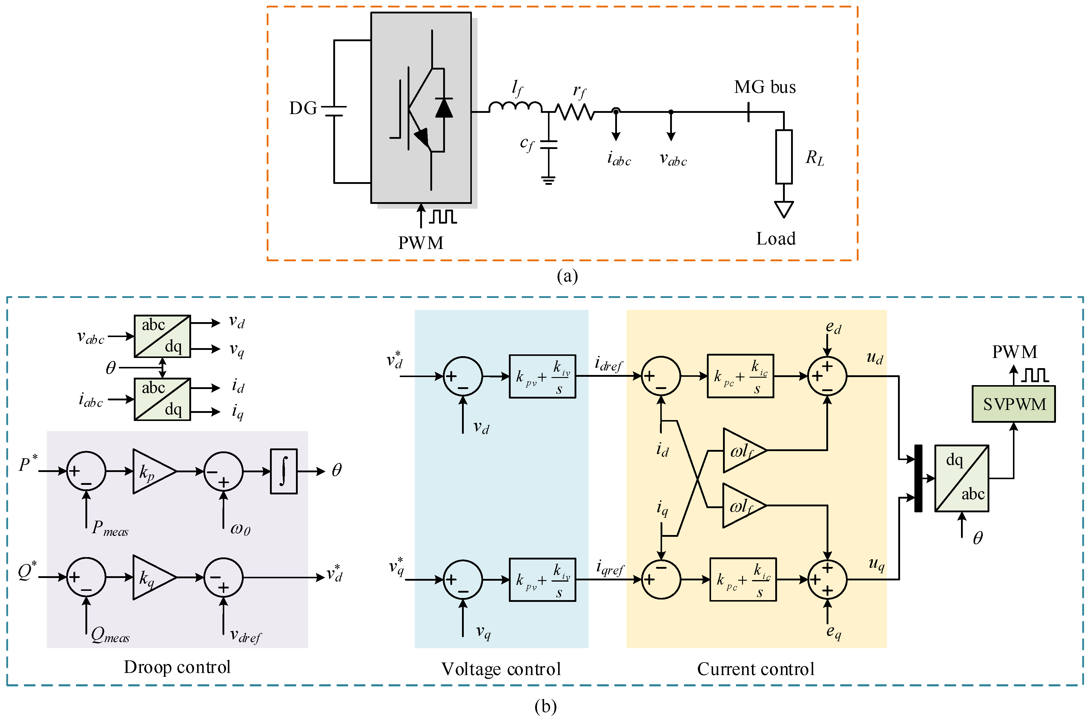
The topology of an inverter-based DG that plays a role of grid-forming converter is shown in Figure 1. The overall control system of DG shown in Figure 1b includes three cascaded loops: current loop, voltage loop, and droop power control loop.
The outputs of the current control loop are the modulating signals, ud and uq, given by:
where kpc and kic are the PI parameters of the current control loop.
The reference currents, idref and iqref, are generated by the voltage control loop, and given by:
where kpv and kiv are the PI parameters of the voltage control loop.
Voltage references, and , are given by the output of the droop power control loop, in which the is generally set to zero and is defined by Equation (5):
where is the reference voltage of the MG system; is the reference reactive power; and is the reactive power droop gain.
The reference angle, θ, is generated by the droop real power, given by:
where is the reference angular frequency; is the reference real power; and is the real power droop gain.
The selection of droop gains, and , are given by Equation (7) [32]:
where and are the maximum and minimum angular frequency deviations, respectively, and and are the maximum and minimum voltage deviations, respectively.
3. A Stand-Alone MMG System and Proposed Multi-Frequency Control
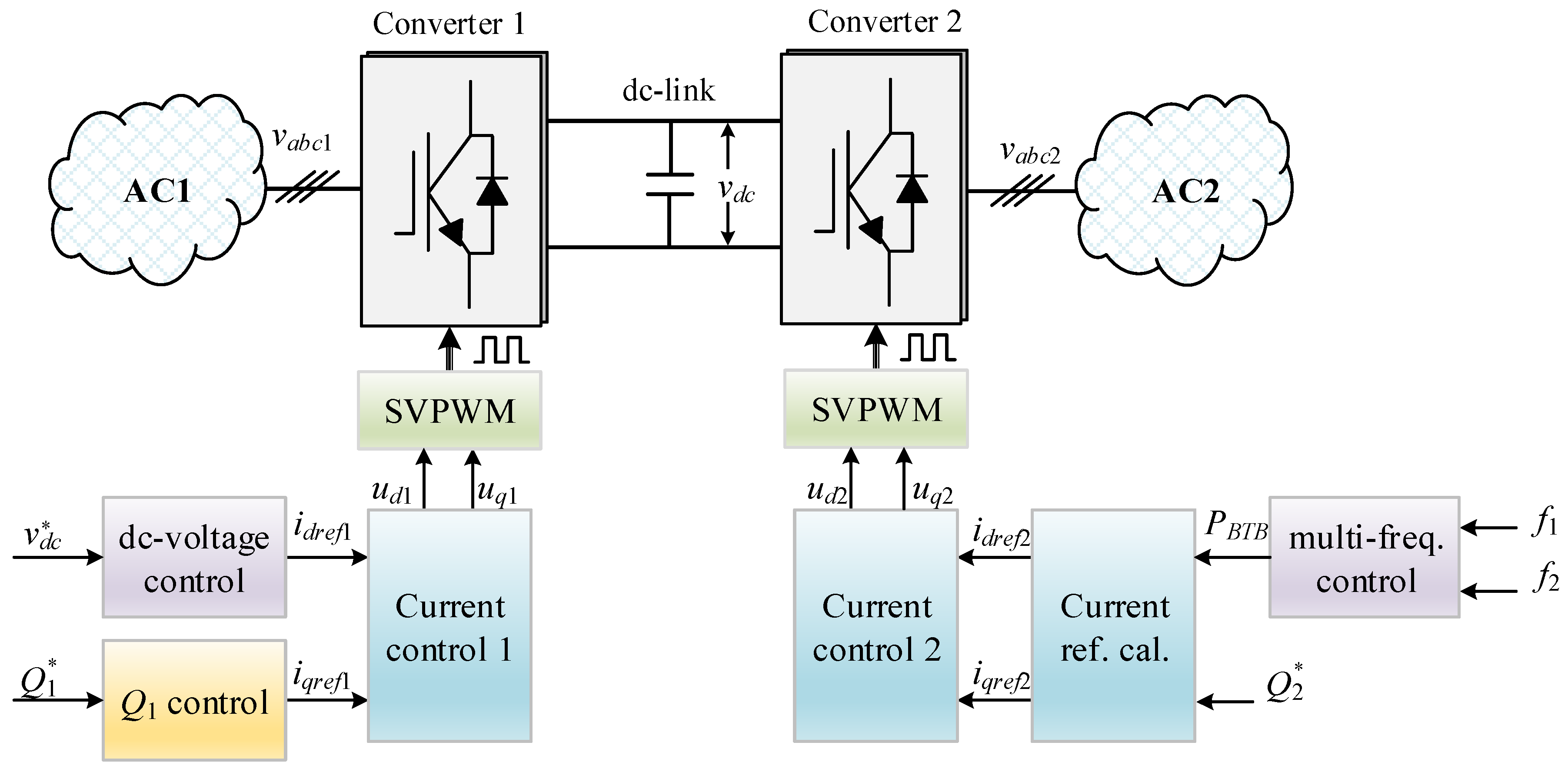
The proposed MMG system is shown in Figure 2, where a BTB converter based on a two-level voltage-source-converter (VSC) is used for interconnecting two adjacent MGs. The BTB converter consists of converters 1 and 2, in which Converter 1 is responsible for the regulation of the dc-link voltage whereas Converter 2 is used for regulating the frequencies of two adjacent MGs. In each MG, the inverter-based DG with the conventional droop control scheme is used.
3.1. Control Diagram of Converter 1
The function of Converter 1 is to regulate the dc-kink voltage of the BTB converter. The cascaded control loops, which consist of current and voltage control loops, are based on synchronous reference frame control. The schematic diagram of the cascaded control loops is shown in Figure 3.
By using the synchronous reference frame control, the control variables such as three-phase voltage and current are converted into dc value (dq-frame). The outputs of current control loop are the modulating signals, ud1 and uq1, as given by:
where and are the reference and measured currents of MG1, respectively; kpc and kic are the proportional–integral (PI) parameters of current control loop; is the angular frequency of MG1.
The dq-current of the converter can be independently controlled, in which the reactive power of MG1 (Q1) is controlled by the d-current, given by:
where is the reference reactive power; is the measured reactive power; and are the PI parameters of the voltage controller.
The reference current is generated by the outer dc-link voltage controller, as given by:
where and are the reference and measured dc-voltages of the BTB converter, respectively; and are the PI parameters of the dc-link voltage controller.
3.2. Multi-Frequency Control for Converter 2
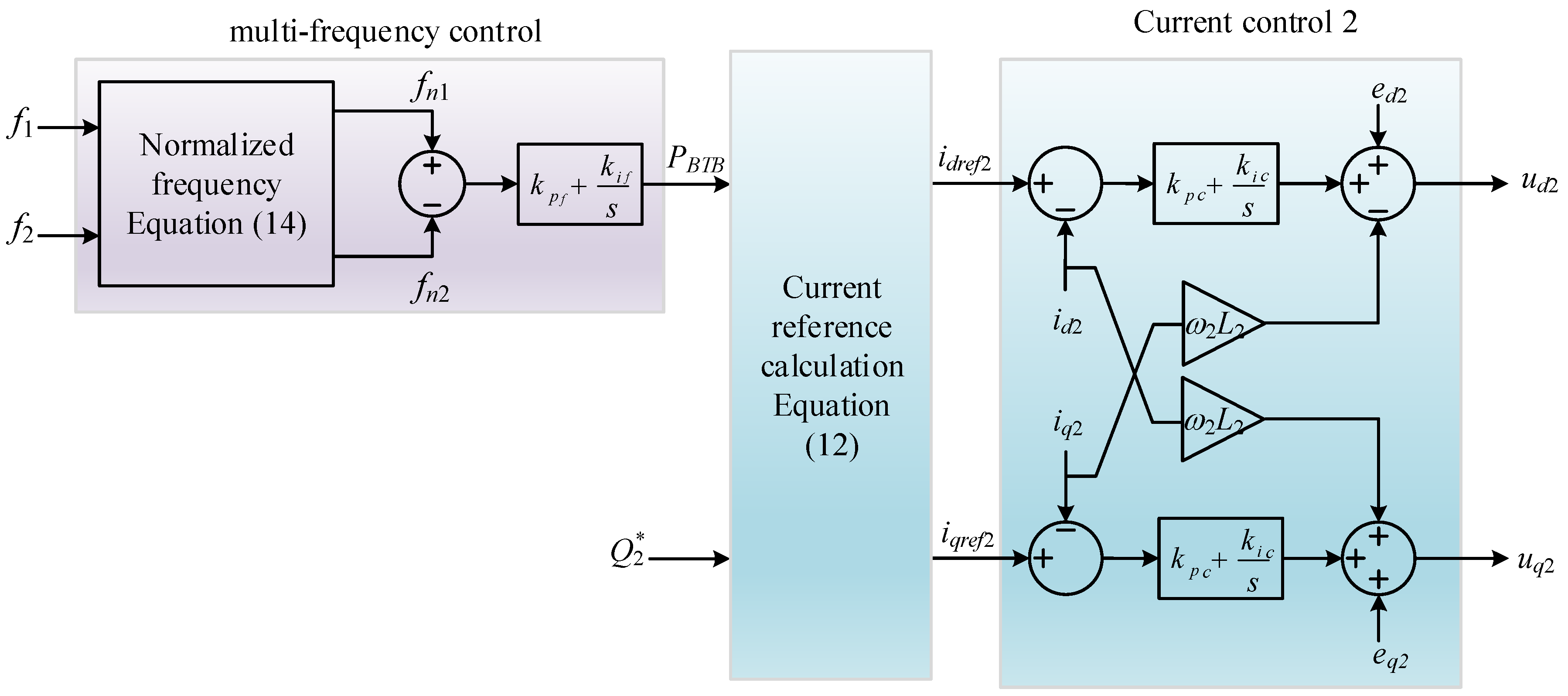
Converter 2 is responsible for the multi-frequency control of two MGs. The control diagram of Converter 2 is shown in Figure 4, which includes the Current Control 2, reactive power control (Q2), and the multi-frequency control loop. The schematic diagram of Current Control 2 is similar to that of Current Control 1. The reference currents, and , are generated by the reference real and reactive power, as shown in Equation (12). The reference real power (PBTB) is given by the outer multi-frequency controller, as in Equation (13):
where and are the normalized frequencies of MGs 1 and 2, respectively; and are the PI parameters of the multi-frequency controller, respectively.
The frequency of each MG is normalized to achieve the unique value of frequency deviation. Equation (14) shows the normalized frequency of MGi.
where, represents the measured frequency of MGi; is the rated frequency of MGi; and are the maximum and minimum frequency deviations, respectively; is the normalized frequency of MGi.
The operation principle of the proposed multi-frequency control is explained in Figure 5. Initially, the normal operation points of two MGs are A1 and A2. It is assumed that the load in MG1 increases suddenly, which results in the reduction of MG1 frequency from f01 to f1′. The operation point of MG1 is changed from A1 to B1. Owing to the use of the proposed multi-frequency control, the power through the BTB converter (PBTB) calculated by Equation (13) is transferred to MG1 to compensate for the load disturbance. As a result, the MG1 frequency is recovered gradually whereas the MG2 frequency decreases slightly. The system frequencies of two MGs are stable at new steady-state values (C1 and C2) when the normalized frequencies of two MGs are equal.
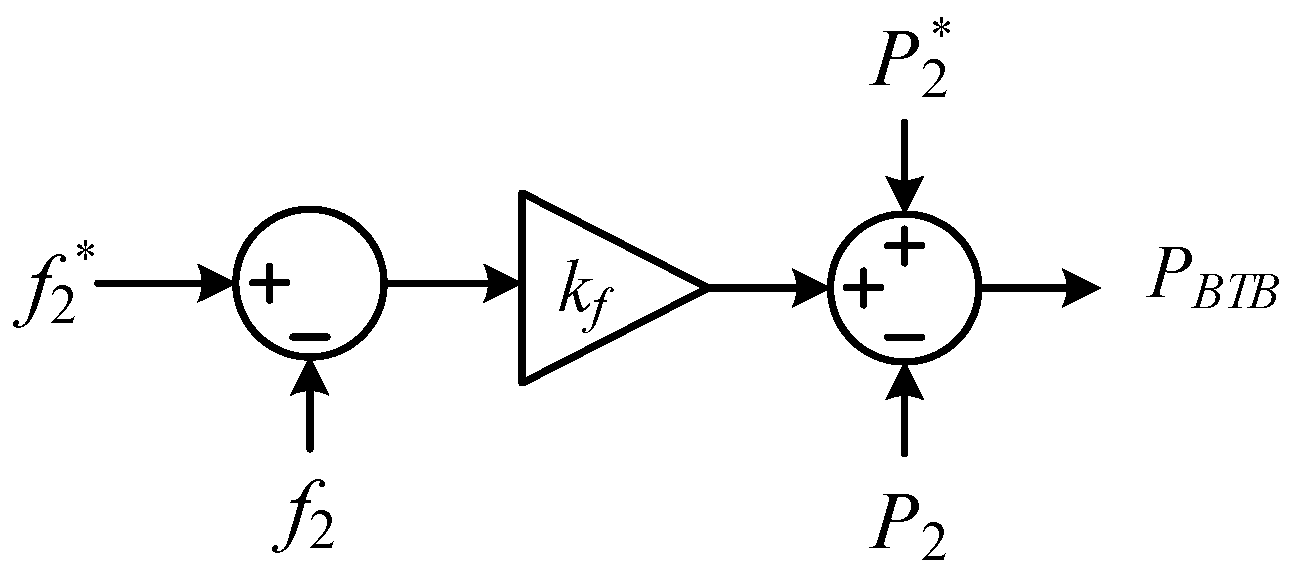
To evaluate the effectiveness of the proposed multi-frequency control, the single frequency droop control that can control only one MG frequency (either MG1 or MG2) is implemented in Converter 2 to compare with the proposed multi-frequency control. This study considers the droop frequency of MG2 (f2) for the comparison. The control diagram of the single frequency droop control of MG2 is shown in Figure 6 where kf is the droop gain of MG2 frequency.
4. Simulation Results
The proposed multi-frequency control is tested firstly on a simple MMG system that consists of two stand-alone MG systems. Several load change scenarios are considered in this case. The complex MMG system that consists of three stand-alone MG systems was tested secondly. In each MG system, wind generations and ESSs are included to evaluate the performance of the proposed multi-frequency control. The detailed case simulation study using the Matlab/Simulink software (MathWorks, Natick, MA, USA) was performed. The fixed-step solver with the ode3 algorithm is adopted to simulate the model with the step size of 50 μs. The switching frequency of the BTB converters is equal to 10 kHz.
4.1. Simple MMG system
Each MG in the MMG system consists of an inverter-based DG and a load. The configuration of the MMG system is shown in Figure 7 and the nominal power of each component is listed in Table 1.
The dynamic performance of the proposed multi-frequency control is evaluated by simulating the MMG system under load change conditions. Three cases are considered in this study, as follows:
- Case 1: 10 kW load connects to MG1 at 3 s and 20 kW load disconnects from MG1 at 7 s.
- Case 2: 10 kW load connects to MG2 at 3 s and 20 kW load disconnects from MG2 at 7 s.
- Case 3: 10 kW load connects to MG1 at 3 s and 10 kW load connects to MG2 at 7 s.
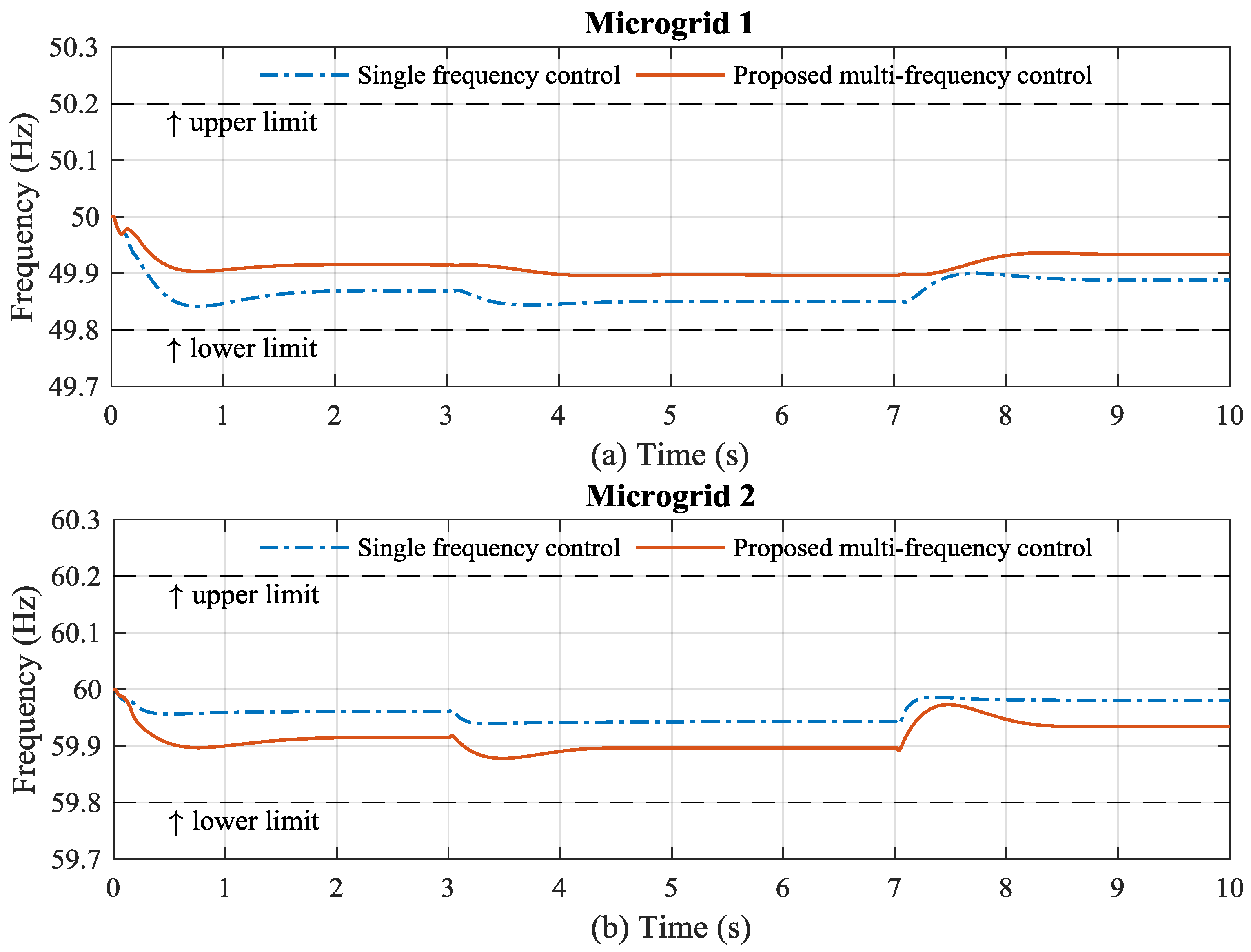
Figure 8 shows two frequencies of the MMG system using either single frequency control or the proposed multi-frequency control in Case 1. It can be seen that the frequencies of two MGs are regulated stably within the allowable frequency deviation (±0.2 Hz for both MGs). Initially, the single frequency controller used in each DG results in the steady-state error of the frequency. At 3 s, the 10 kW load connects to MG1 causing a slight reduction of the frequency in MG1. 20 kW load disconnection from MG1 results in the increase of the MG1 frequency. By using either single frequency control or the proposed frequency control in the BTB converter, the MG1 frequency trends are similar. However, in the MMG system with the single frequency control, the frequency deviation of MG1 is larger than that in the MMG system with the proposed frequency control. The MG2 frequency in the case of the MMG system with the single frequency control remains constant because there is no disturbance in MG2. In the case of the MMG with the proposed multi-frequency control, the frequencies of both MGs are considered in the BTB converter. The disturbance in MG1 can be recognized by the proposed multi-frequency control. The power reserve in MG2 can then be shared accordingly to recover the MG1 frequency. As a result, the MG2 frequency is deviated by the disturbance in MG1.
The frequency deviations of two MGs with the disturbance of load in MG2 are shown in Figure 9. The frequencies of the two MGs are regulated stably in the allowable frequency deviation range. In the case of the MMG system with the single frequency control, the MG2 frequency deviation is smaller than that in the MMG system with the proposed frequency control. The load disturbance in MG2 leads to the change of MG2 frequency (f2) that is used for the single frequency control in the BTB converter. As a result, the power reserve in MG1 can be shared with MG2 to recover the MG2 frequency. However, the frequency deviation of MG1 in the MMG system with the single frequency control is larger than that of the MMG system with the proposed multi-frequency control, even though there is no disturbance in the MG1 system.
Case 3 simulates load disturbances in both MGs. Figure 10 shows the frequency deviations of two MGs in the MMG system using either the single frequency control or the proposed multi-frequency control. It can be seen that the MMG system with the single frequency control is stable until the 10 kW load connects to MG2. The load disturbance in MG2 leads to the reduction of the MG2 frequency. The power reserve of MG1 is transferred to MG2 through the BTB converter to recover the MG2 frequency, which results in the drop in the MG1 frequency out of the allowable frequency deviation range, as shown in Figure 10a. By comparison, the proposed multi-frequency control can regulate stably the frequencies of the two MGs in this case. By considering both frequencies in the multi-frequency control of the BTB converter, the stability of the MMG system can be improved.
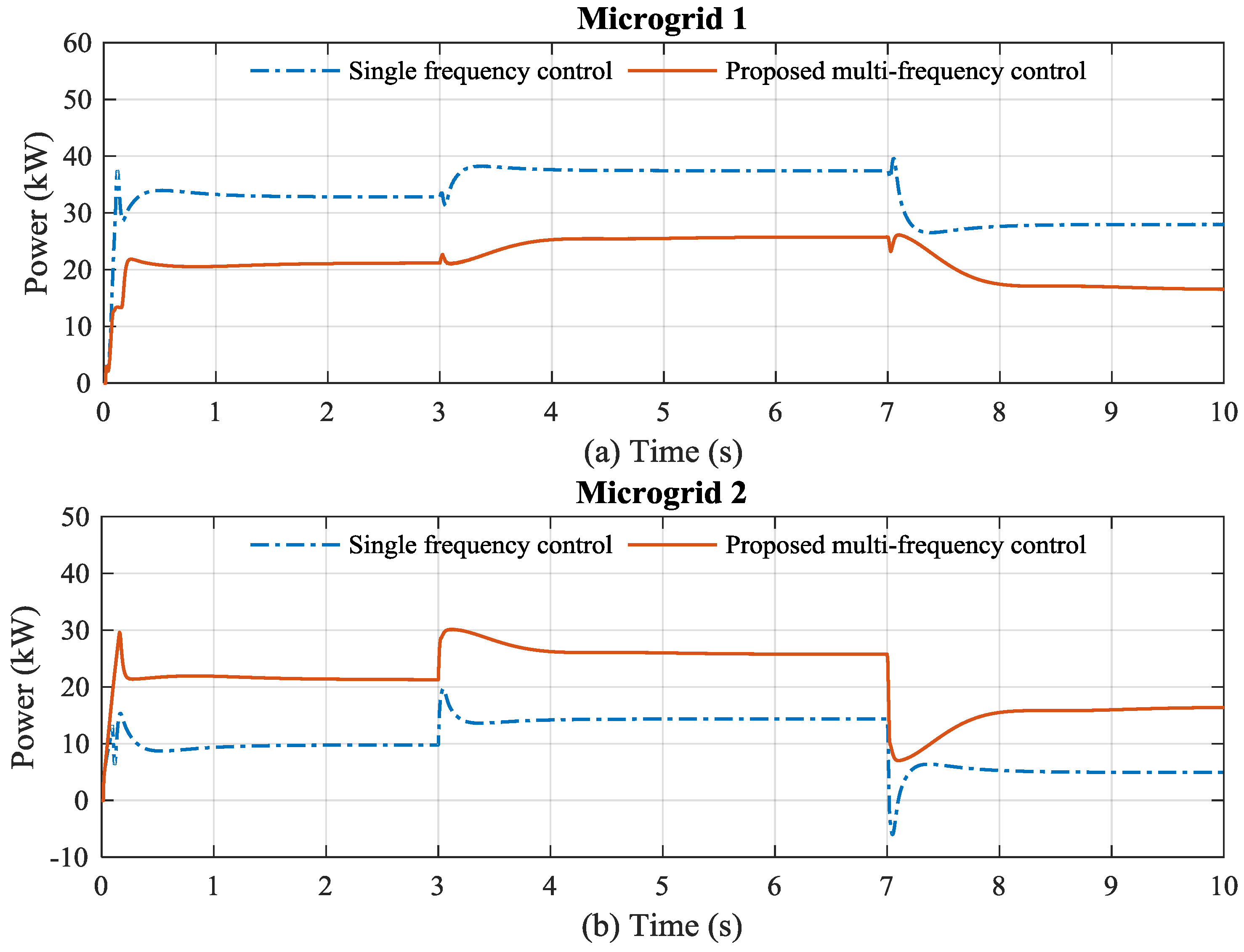
The inverter-based DG with the droop controller is responsible for the primary frequency control in each MG. The power of the DG should be generated rapidly to compensate for the load disturbance. Figure 11 shows the DG output power of two MGs in Case 1 where the load disturbance is only in the MG1. In the case of the MMG system with the single frequency control in the BTB converter, the DG1 compensates fully for the load change whereas the DG2 output power is maintained constant during the load disturbance in MG1. It is observed that the MG2 does not support the load disturbance in the MG1 system if the single frequency control scheme is used in the BTB converter. By comparison, in the case of the MMG system with the proposed multi-frequency control, the MG2 system can support the load disturbance in the MG1 system by regulating the DG2 power output. As a result, the DG1 power output can be reduced as compared to the case of the MMG system with the single frequency control.
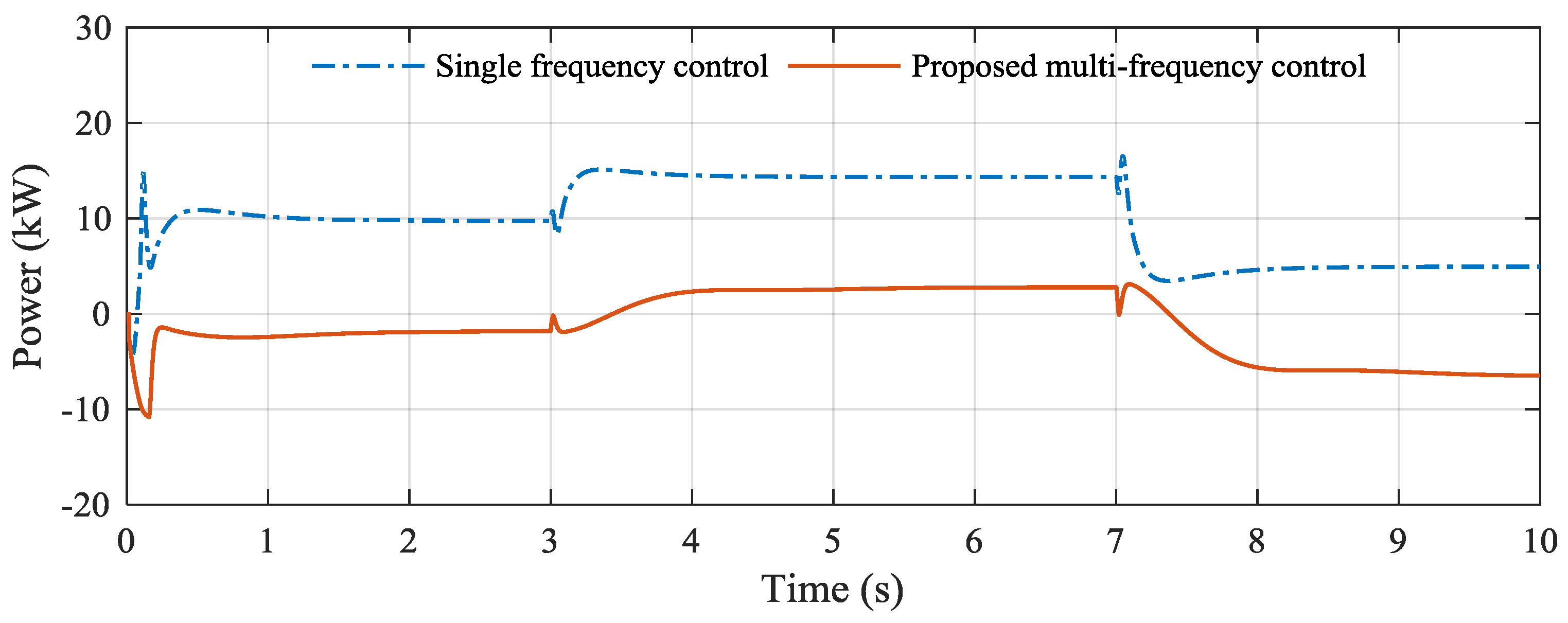
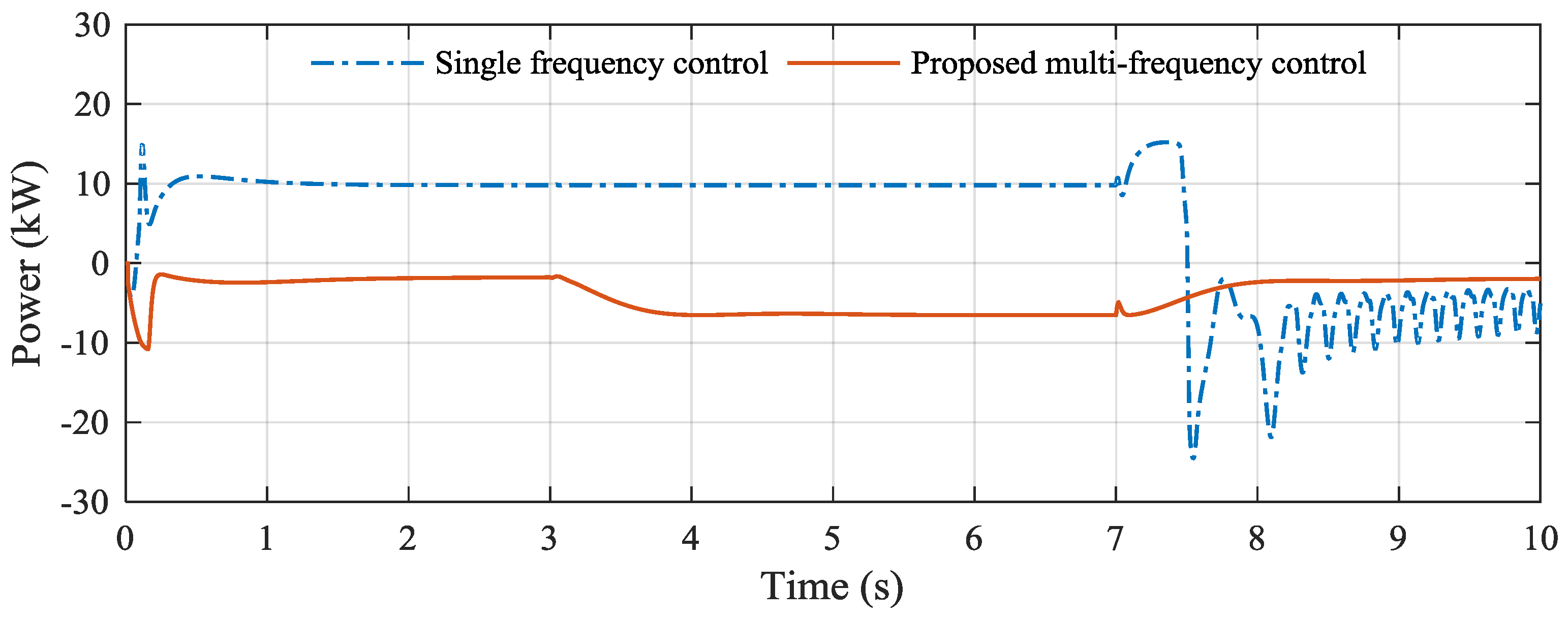
The single frequency control of the BTB converter is only effective in the case of load change in MG2, as shown in Figure 12. The MG1 system can support for the load change in the MG2 system by adjusting the output power of DG1. However, the DG1 output power nearly reaches the power rating whereas the DG2 output power is much lower than the DG1 output power. In Case 3 where the load disturbances are in both MGs, the MMG system with the single frequency control is unstable when the load in MG2 is connected at 7 s, as shown in Figure 13. The DG1 output power reaches the maximum value, which results in a drop in the MG1 frequency below the lower limit. Since there is no additional power source to compensate for the drop in frequency, the MG1 system becomes unstable. By comparison, the proposed multi-frequency control still stably maintains the frequencies of the two MGs system. The power of each DG can be effectively shared by the proposed multi-frequency control to improve the stability of the MMG system.
In the case of the MMG system where the adjacent MG system is interconnected by the BTB converter, the power reserve can be shared through the BTB converter to improve the system frequency. Depending the control scheme of the BTB converter, the sharing power between each MG is different. Figure 14, Figure 15 and Figure 16 show the power sharing of two MGs in three cases. In the case of the MMG system with the single frequency control, it can be seen that the power of MG1 is always transferred to the MG2 system. As a result, the MG2 frequency deviation is much smaller than the MG1 frequency. In the case of the MMG system with the proposed multi-frequency control, the bidirectional power sharing between two MGs is effectively achieved according to the load change in the MMG system.
4.2. Complex MMG system
The proposed multi-frequency control is tested on the complex MMG system that consists of three stand-alone MG systems, as shown in Figure 17. Each stand-alone MG system consists of a wind turbine generator (WTG) and an energy storage system (ESS). The WTG is based on the induction generator for the sake of simplicity. The nominal powers of three WTGs are equal to 40 kVA. The ESS converter is based on the grid-forming converter to maintain the system frequency and voltage. The nominal powers of three ESSs are the same to the DG rating, as mentioned in Section 4.1. The nominal load powers of MG1 and MG3 are 20 kW whereas the nominal load power of MG2 is 25 kW. The nominal frequency of MG2 is 60 Hz while those of the other MGs are 50 Hz. The MG1 and MG3 systems are connected to the MG2 through the BTB12 and BTB23, respectively. The frequency control performance of the proposed multi-frequency control is compared with the single frequency control.
The wind speed and output power of three WTGs are shown in Figure 18. It is assumed that the wind speed of the WTG2 in the MG2 system fluctuates significantly, which results in a significant fluctuation in the MG2 frequency. Therefore, two BTB converters control the MG2 frequency in the case of the single frequency control scheme. The single frequency control scheme is mentioned in Section 4.1. In the case of multi-frequency control scheme, the BTB12 regulates the MG1 and MG2 frequencies whereas the BTB23 control MG2 and MG3 frequencies.
Figure 19 shows the frequencies of three MG systems in the case of single and multi-frequency control scheme. Both control strategies can regulate the frequency of each MG system stably within the acceptable deviation range. It is observed that the deviation of MG2 frequency in the case of single frequency control strategy is smaller than that of the multi-frequency control strategy because two BTB converters are used for controlling the MG2 frequency only in the case of the single frequency control strategy. The trend of MG2 frequency in this case is similar to the result obtained in the previous section (Figure 9). The MG1 and MG3 frequency deviations in the case of single frequency control strategy is larger than those of the multi-frequency control strategy. There is a trade-off between the MG2 frequency and other MG frequencies. Using the single frequency control strategy in the MMG system, only one MG system can be supported by other MGs. By comparison, in the MMG system with the use of the multi-frequency control strategy, all MG systems can support others to maintain their frequencies in the acceptable ranges. Overall, it should be better to regulate all frequencies in the MMG system instead of only one MG frequency. The proposed multi-frequency control strategy could bring the benefits of autonomous sharing power between each MG system.
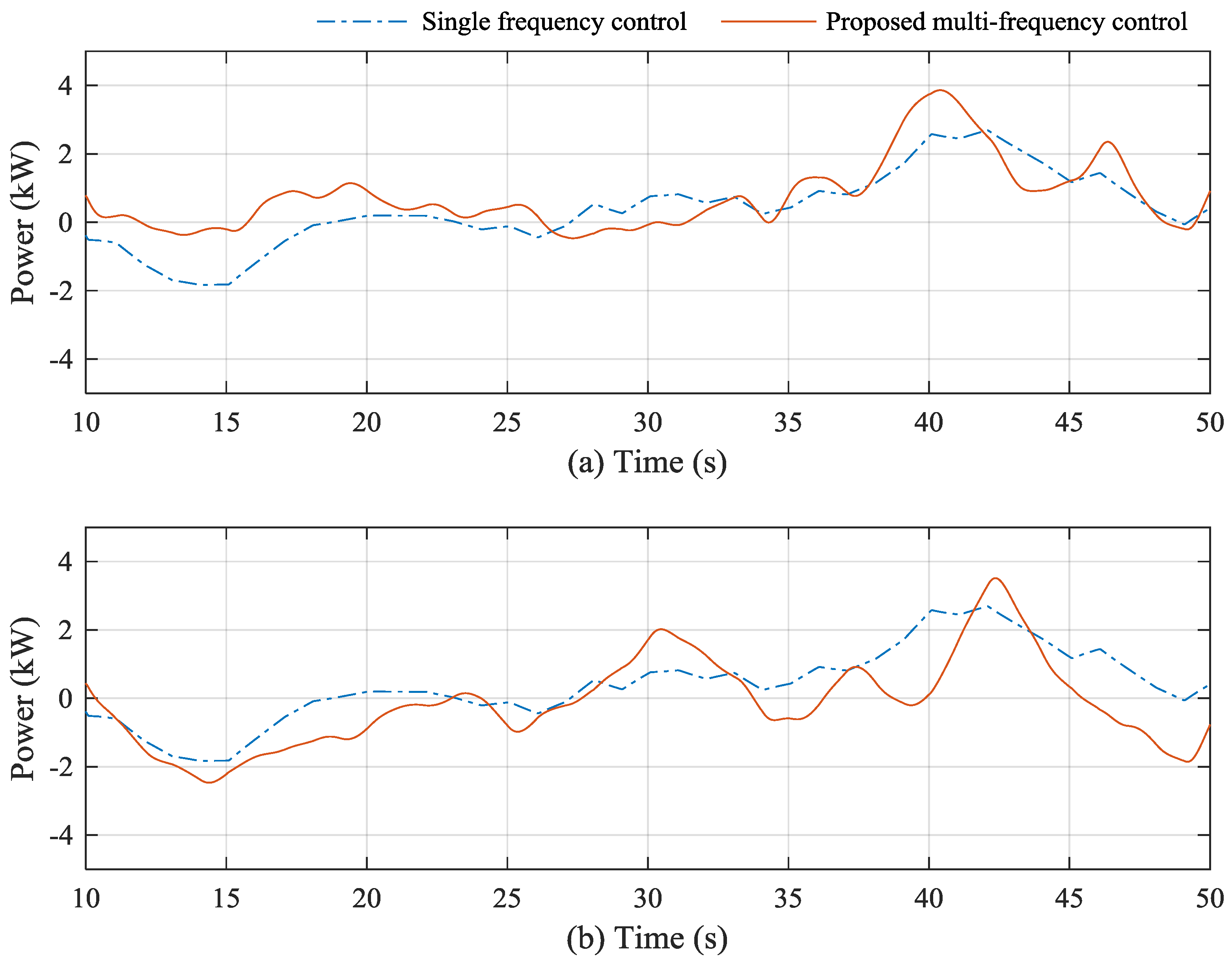
The ESS output powers in three MG systems are shown in Figure 20. The main function of the ESS is to regulate the system frequency and voltage. In the proposed MMG system, the main power supply for the load is the wind generations. To maintain the system frequency and voltage, the ESS should compensate for the fluctuation in wind power output. It can be seen at around 15 s in Figure 20, that the ESS operates in the charging mode when the output power of WTG is high. From 40 s to 45 s, since the output WTG is lower than the load demand, the ESS supplies the additional power for the load. In the case of MMG system with the use of single frequency control strategy, the ESS2 output power is lower than that of the multi-frequency control strategy, whereas the output powers of ESS1 and ESS3 are larger than those in case of the multi-frequency control. As a result, for the long-term operation of the MMG system with the use of the single frequency control strategy, the state-of-charge (SoC) of the ESS1 and ESS3 might reach to the limit faster than the case of using multi-frequency control strategy. The proposed multi-frequency control strategy might have a positive impact on the SoC of ESSs in the MMG system.
The power sharing through the BTB converters is shown in Figure 21. The positive power of the BTB converters represent for the power transfer to the MG2 system. It can be seen that MG1 and MG3 mostly transfer power to the MG2 system in the case of single frequency control strategy. The MG2 system transfers power to the MG1 and MG3 systems only in the case of high power of WTG2 (around 15 s). By comparison, the power sharing between each MG system can be achieved equally by using the multi-frequency control strategy. The MG2 power can be transferred to the MG3 system when the output power of the WTG3 is low (at around 35 s and 48 s).
5. Conclusions
A stand-alone MMG system with the use of a BTB converter for interlinking the adjacent MG systems has been presented in this study. The multi-frequency control implemented in the BTB converter has been proposed for managing the frequencies of multiple MG systems. A comparison study of the single frequency control and multiple frequency control has been presented. The drawback of the single frequency control of the BTB converter is the existence of the trade-off between each of MG frequencies, in which the MG2 frequency is much better than other frequencies. As a result, it is suitable for the MMG system where one MG system requires high-quality frequency. By comparison, the proposed multi-frequency control can address the drawback of the single frequency control by compensating for disturbances in all MGs. The frequency deviations of all MG system can be achieved equally with the use of the proposed control strategy for the BTB converters. The multi-frequency control strategy is suitable for MMG systems in which the penetration of renewable generation in each MG system is high due to the ability of bidirectional sharing power between each MG system. The proposed multi-frequency control is a simple approach to regulate multiple frequencies in the MMG system compared to the other frequency control algorithms. The proposed strategy does not require any communication system for regulating multiple frequencies, thus, it can be easily applied for the extended MMG system with more stand-alone MG systems. The proposed control strategy also can be applied for the MMG system where the frequency quality of each MG system is different. Coordinated frequency control between the ESS of each MG system and the BTB converter using proposed multi-frequency control might bring better performance of frequency regulation, which will be considered in our future work.
Acknowledgments
This work was supported by the Power Generation & Electricity Delivery Core Technology Program of the Korea Institute of Energy Technology Evaluation and Planning (KETEP), granted financial resource from the Ministry of Trade, Industry & Energy, Republic of Korea (No. 20141020402350).
Author Contributions
The paper was a collaborative effort between the authors. The authors contributed collectively to the theoretical analysis, modeling, simulation, and manuscript preparation.
Conflicts of Interest
The authors declare no conflict of interest.
References
- Nikmehr, N.; Najafi, R.S. Reliability Evaluation of Multi-Microgrids Considering Optimal Operation of Small Scale Energy Zones under Load-Generation Uncertainties. Int. J. Electr. Power Energy Syst. 2016, 78, 80–87. [Google Scholar] [CrossRef]
- Arefifar, S.A.; Ordonez, M.; Mohamed, Y.A.I.; Member, S. Energy Management in Multi-Microgrid Systems—Development and Assessment. IEEE Trans. Power Syst. 2017, 32, 910–922. [Google Scholar] [CrossRef]
- Song, N.-O.; Lee, J.-H.; Kim, H.-M. Optimal Electric and Heat Energy Management of Multi-Microgrids with Sequentially-Coordinated Operations. Energies 2016, 9, 473. [Google Scholar] [CrossRef]
- Chanda, S.; Srivastava, A.K.; Member, S. Electric Distribution Systems with Multiple Microgrids. IEEE Trans. Smart Grid. 2016, 7, 2859–2868. [Google Scholar] [CrossRef]
- Hussain, A.; Bui, V.-H.; Kim, H.-M. Robust Optimization-Based Scheduling of Multi-Microgrids Considering Uncertainties. Energies 2016, 9, 278. [Google Scholar] [CrossRef]
- Farzin, H.; Member, S.; Fotuhi-firuzabad, M. Enhancing Power System Resilience through Hierarchical Outage Management in Multi-Microgrids. IEEE Trans. Smart Grid. 2016, 7, 2869–2879. [Google Scholar] [CrossRef]
- Hossain, M.J.; Mahmud, M.A.; Milano, F.; Bacha, S.; Hably, A. Design of Robust Distributed Control for Interconnected Microgrids. IEEE Trans. Smart Grid 2016, 7, 2724–2735. [Google Scholar] [CrossRef]
- Suh, J.; Yoon, D.H.; Cho, Y.S.; Jang, G. Flexible Frequency Operation Strategy of Power System with High Renewable Penetration. IEEE Trans. Sustain. Energy. 2017, 8, 192–199. [Google Scholar] [CrossRef]
- Liu, W.; Gu, W.; Xu, Y.; Wang, Y.; Zhang, K. General Distributed Secondary Control for Multi-Microgrids with Both PQ-Controlled and Droop-Controlled Distributed Generators. IET Gener. Transm. Distrib. 2017, 11, 707–718. [Google Scholar] [CrossRef]
- Zamora, R.; Srivastava, A.K.; Member, S. Multi-Layer Architecture for Voltage and Frequency Control in Networked Microgrids. IEEE Trans. Smart Grid 2016, PP. [Google Scholar] [CrossRef]
- Wu, J.; Guan, X. Coordinated Multi-Microgrids Optimal Control Algorithm for Smart Distribution. IEEE Trans. Smart Grid 2013, 4, 2174–2181. [Google Scholar] [CrossRef]
- Chiu, W.; Sun, H.; Poor, H.V.A. Multiobjective Approach to Multimicrogrid System Design. IEEE Trans. Smart Grid 2015, 6, 2263–2272. [Google Scholar] [CrossRef]
- Yuen, C.; Oudalov, A.; Timbus, A. The Provision of Frequency Control Reserves from Multiple Microgrids. IEEE Trans. Ind. Electron. 2011, 58, 173–183. [Google Scholar] [CrossRef]
- Wang, C.; Yang, P.; Ye, C.; Wang, Y.; Xu, Z.; Member, S. Voltage Control Strategy for Three/Single Phase Hybrid Multimicrogrid. IEEE Trans. Energy Convers. 2016, 31, 1498–1509. [Google Scholar] [CrossRef]
- Arefifar, S.A.; Ordonez, M.; Mohamed, Y.A.I. Voltage and Current Controllability in Multi-Microgrid Smart Distribution Systems. IEEE Trans. Smart Grid 2016, PP. [Google Scholar] [CrossRef]
- Nutkani, I.U.; Loh, P.C.; Wang, P.; Jet, T.K.; Blaabjerg, F. Intertied AC-AC Microgrids with Autonomous Power Import and Export. Int. J. Electr. Power Energy Syst. 2015, 65, 385–393. [Google Scholar] [CrossRef]
- Nutkani, I.U.; Loh, P.C.; Member, S.; Blaabjerg, F. Distributed Operation of Interlinked AC Microgrids with Dynamic Active and Reactive Power Tuning. IEEE Trans. Ind. Appl. 2013, 49, 2188–2196. [Google Scholar] [CrossRef]
- Kargarian, A.; Rahmani, M. Multi-Microgrid Energy Systems Operation Incorporating Distribution-Interline Power Flow Controller. Electr. Power Syst. Res. 2015, 129, 208–216. [Google Scholar] [CrossRef]
- Bala, S.; Venkataramanan, G. Autonomous power electronic interfaces between microgrids. In Proceedings of the IEEE Energy Conversion Congress and Exposition, San Jose, CA, USA, 20–24 September 2009; pp. 3006–3013. [Google Scholar]
- ABB Project Reference: Ross Island, Wind/Diesel System Antarctica. Available online: http://new.abb.com/power-generation/references/ross-island-research-station (accessed on 16 June 2017).
- Majumder, R.; Ghosh, A.; Ledwich, G.; Zare, F. Power Management and Power Flow Control with Back-to-Back Converters in a Utility Connected Microgrid. IEEE Trans. Power Syst. 2010, 25, 821–834. [Google Scholar] [CrossRef]
- Majumder, R. A Hybrid Microgrid with DC Connection at Back to Back Converters. IEEE Trans. Smart Grid 2014, 5, 251–259. [Google Scholar] [CrossRef]
- Niiranen, J.; Komsi, R.; Routimo, M.; Lähdeaho, T.; Antila, S. Experiences from a back-to-back converter fed village microgrid. In Proceedings of the IEEE Innovative Smart Grid Technologies Conference Europe (ISGT Europe), Gothenberg, Sweden, 11–13 October 2010; pp. 1–5. [Google Scholar]
- Majumder, R.; Dewadasa, M.; Ghosh, A.; Ledwich, G.; Zare, F. Control and Protection of a Microgrid Connected to Utility Through Back-To-Back Converters. Electr. Power Syst. Res. 2011, 81, 1424–1435. [Google Scholar] [CrossRef]
- Goyal, M.; Ghosh, A. Microgrids Interconnection to Support Mutually During Any Contingency. Sustain. Energy Grids Netw. 2016, 6, 100–108. [Google Scholar] [CrossRef]
- Susanto, J.; Shahnia, F.; Ghosh, A.; Rajakaruna, S. Interconnected microgrids via back-to-back converters for dynamic frequency support. In Proceedings of the IEEE Power Engineering Conference (AUPEC), 2014 Australian Universities, Perth, WA, Australia, 28 September–1 October 2014; pp. 1–6. [Google Scholar]
- Hagiwara, M.; Akagi, H. An Approach to Regulating the DC-Link Voltage of a Voltage-Source BTB System during Power Line Faults. IEEE Trans. Ind. Appl. 2005, 41, 1263–1271. [Google Scholar] [CrossRef]
- Tang, C.Y.; Chen, Y.F.; Chen, Y.M.; Chang, Y.R. Dc-Link Voltage Control Strategy for Three-Phase Back-To-Back Active Power Conditioners. IEEE Trans. Ind. Electron. 2015, 62, 6306–6316. [Google Scholar] [CrossRef]
- Tang, C.Y.; Tsai, C.J.; Chen, Y.M.; Chang, Y.R. Dynamic Optimal AC Line Current Regulation Method for Three-Phase Active Power Conditioners. IEEE J. Emerg. Select. Top. Power Electron. 2017, 5, 901–911. [Google Scholar] [CrossRef]
- Khederzadeh, M.; Maleki, H.; Asgharian, V. Frequency Control Improvement of two Adjacent Microgrids in Autonomous Mode Using Back to Back Voltage-Sourced Converters. Int. J. Electr. Power Energy Syst. 2016, 74, 126–133. [Google Scholar] [CrossRef]
- Madureira, A.G.; Pereira, J.C.; Gil, N.J.; Lopes, J.A.P.; Korres, G.N.; Hatziargyriou, N.D. Advanced Control and Management Functionalities for Multi-Microgrids. Eur. Trans. Elect. Power 2011, 21, 1159–1177. [Google Scholar] [CrossRef]
- Pogaku, N.; Prodanovic, M.; Green, T.C. Modeling, Analysis and Testing of Autonomous Operation of an Inverter-Based Microgrid. IEEE Trans. Power Electron. 2007, 22, 613–625. [Google Scholar] [CrossRef]
Figure 1.
Single MG system: (a) single MG system; (b) control scheme of the grid-forming converter.

Figure 2.
Typical MMG system using BTB converter.

Figure 3.
The control diagram of Converter 1.
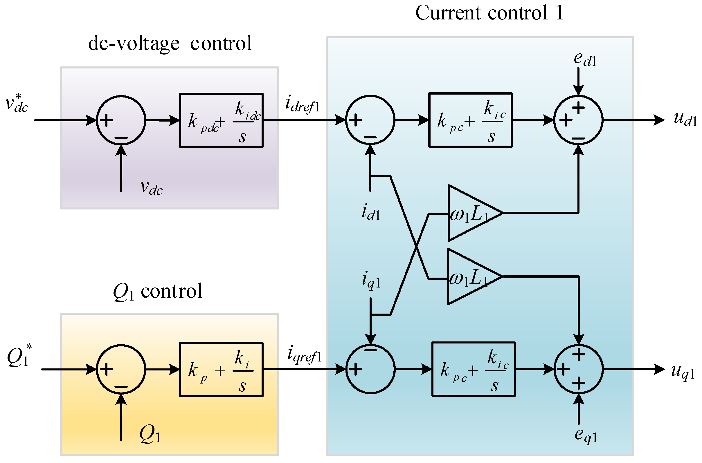
Figure 4.
The control diagram of Converter 2.

Figure 5.
Characteristic of proposed frequency control: (a) droop frequency in MG1; (b) droop frequency in MG2; (c) normalized frequency of MG1; (d) normalized frequency of MG2.
Figure 5.
Characteristic of proposed frequency control: (a) droop frequency in MG1; (b) droop frequency in MG2; (c) normalized frequency of MG1; (d) normalized frequency of MG2.
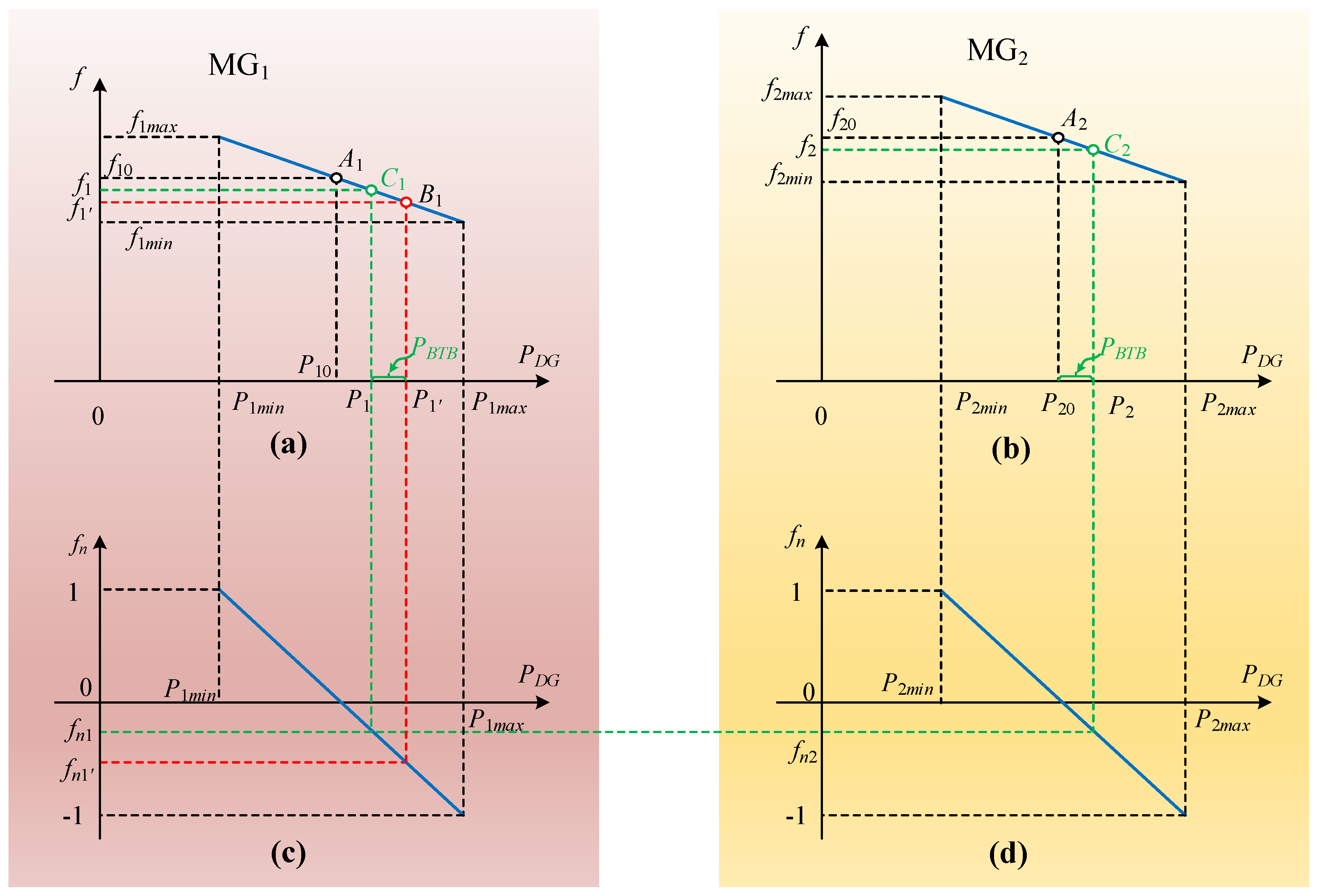
Figure 6.
The single frequency droop control.

Figure 7.
The tested multi-microgrid system.
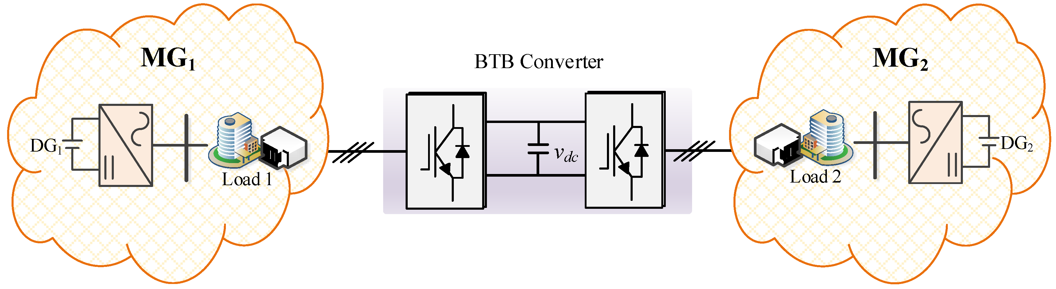
Figure 8.
MG frequencies in the case 1: (a) MG1 frequency; (b) MG2 frequency.
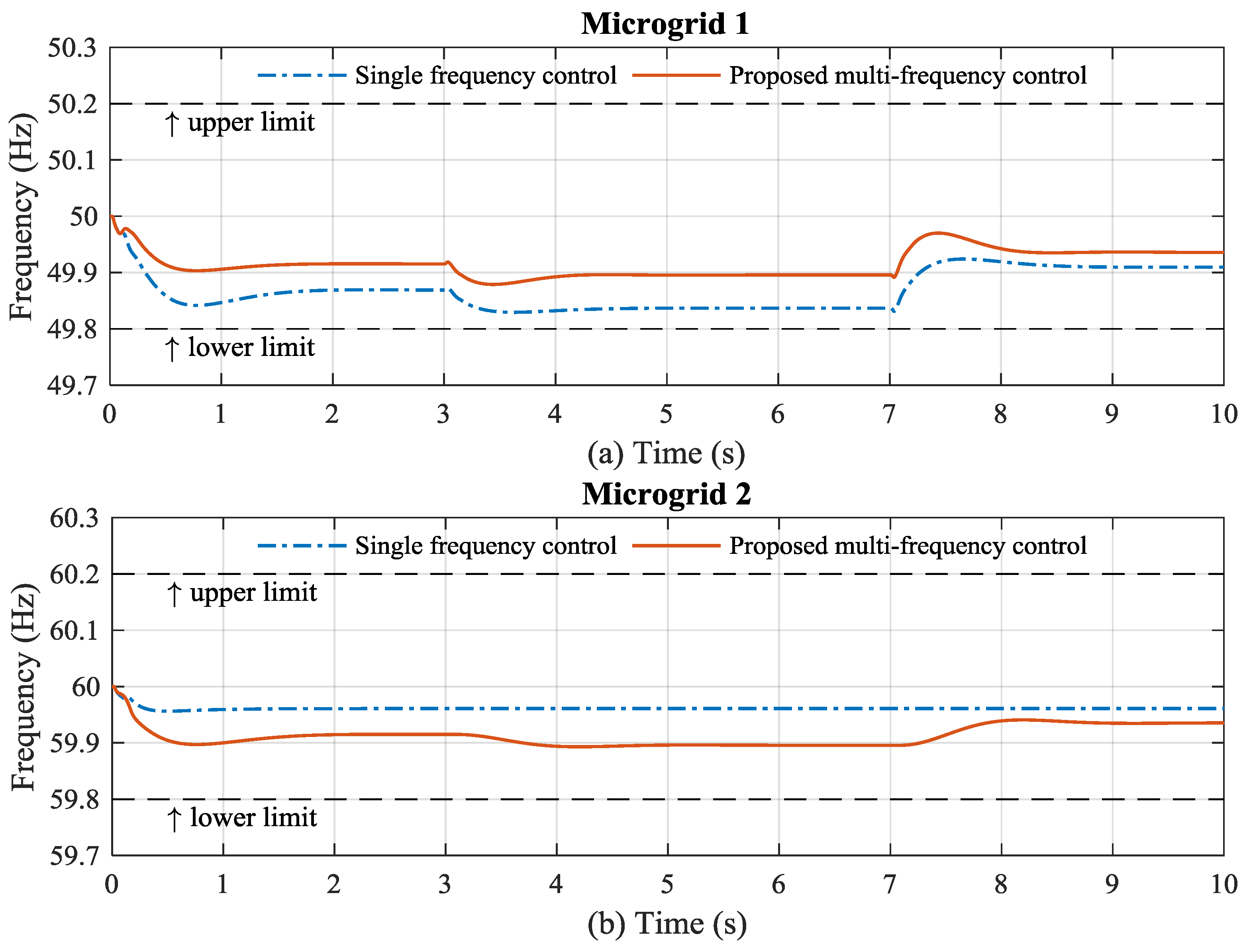
Figure 9.
MG frequencies in the case 2: (a) MG1 frequency; (b) MG2 frequency.

Figure 10.
MG frequencies in the case 3: (a) MG1 frequency; (b) MG2 frequency.

Figure 11.
DG power in the case 1: (a) DG1 power; (b) DG2 power.
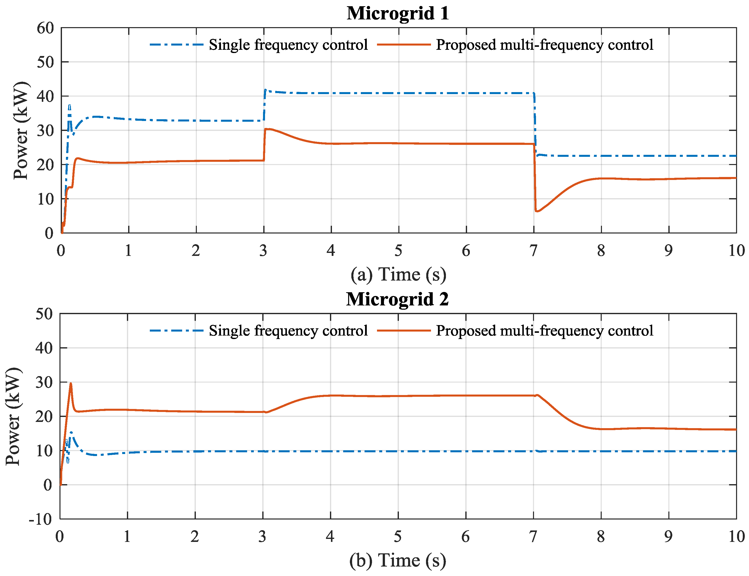
Figure 12.
DG power in the case 2: (a) DG1 power; (b) DG2 power.

Figure 13.
DG power in the case 3: (a) DG1 power; (b) DG2 power.
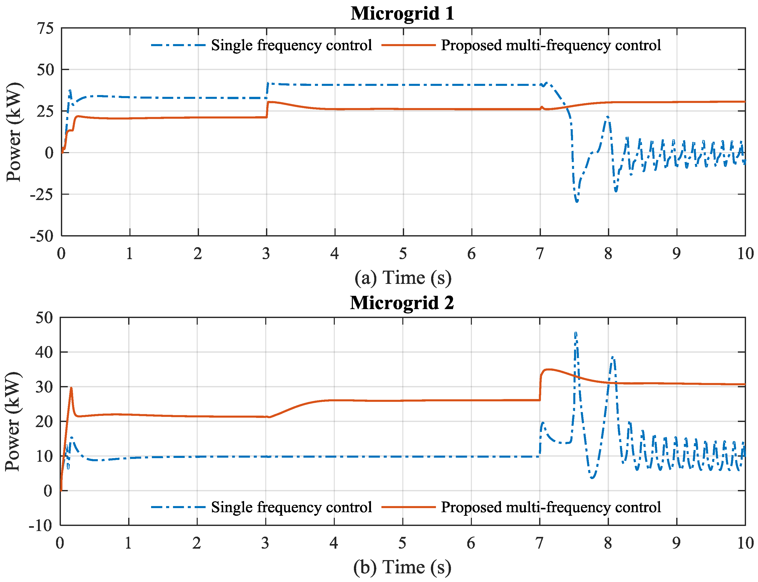
Figure 14.
Power sharing through the BTB converter in the case 1.
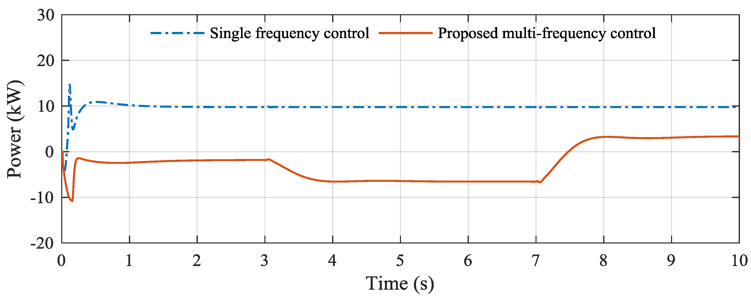
Figure 15.
Power sharing through the BTB converter in the case 2.

Figure 16.
Power sharing through the BTB converter in the case 3.

Figure 17.
Complex MMG system.
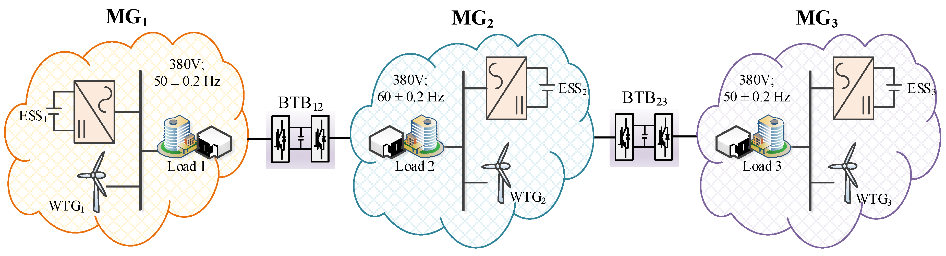
Figure 18.
Wind speed and wind power of WTGs: (a) wind speed; (b) output wind power.
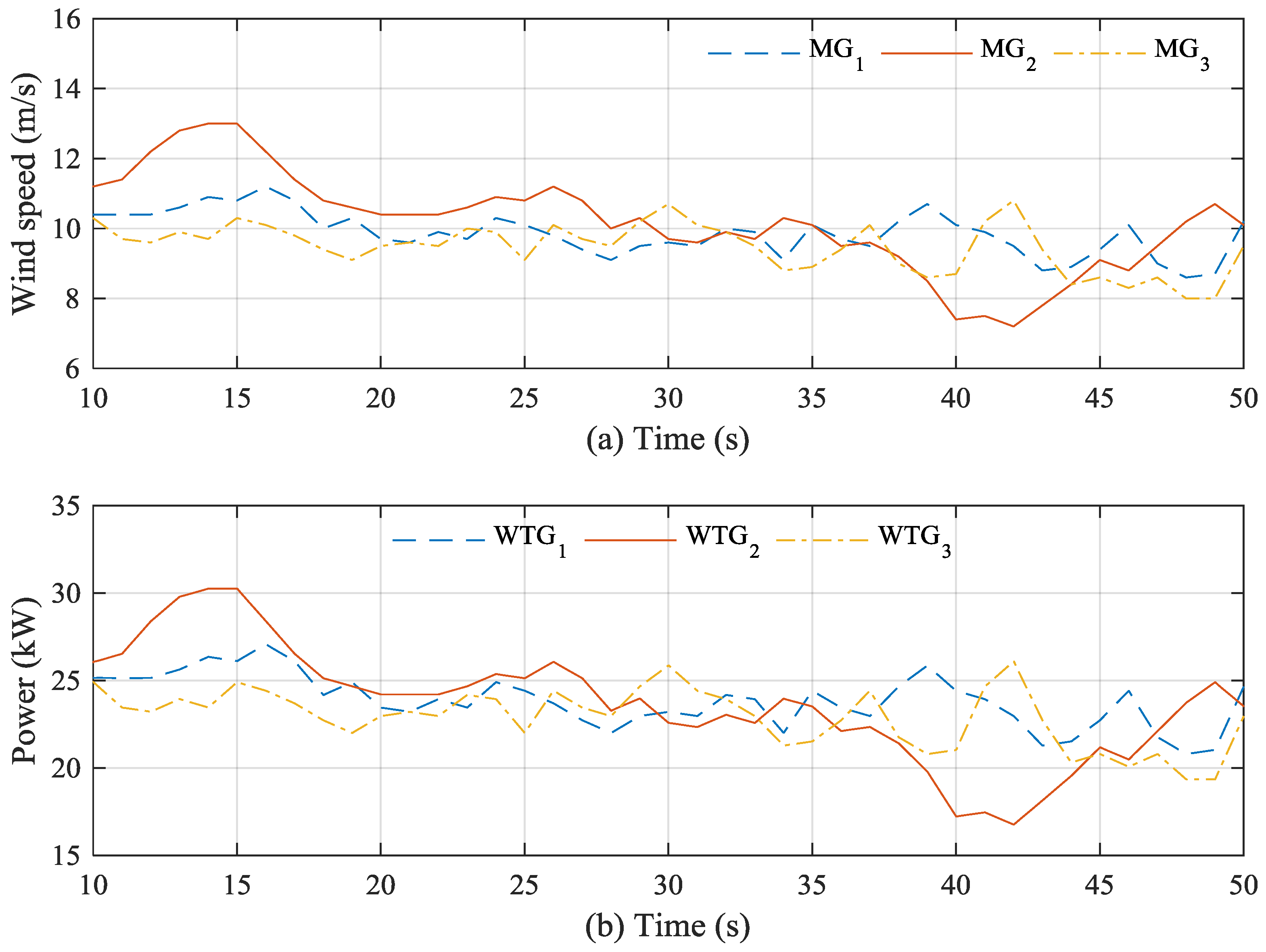
Figure 19.
MG frequencies: (a) MG1 frequency; (b) MG2 frequency; (c) MG3 frequency.
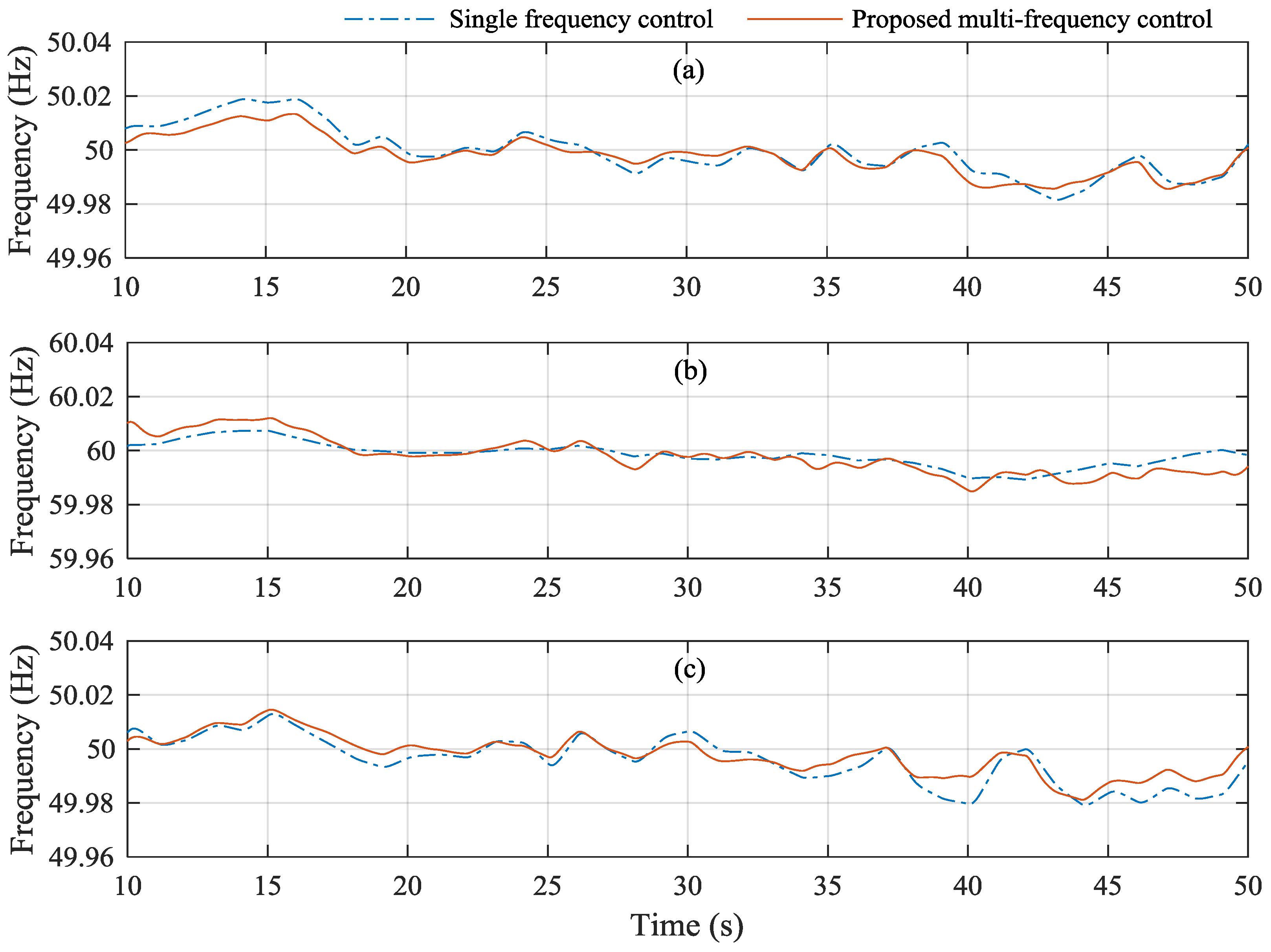
Figure 20.
ESSs powers: (a) ESS1; (b) ESS2; (c) ESS3.
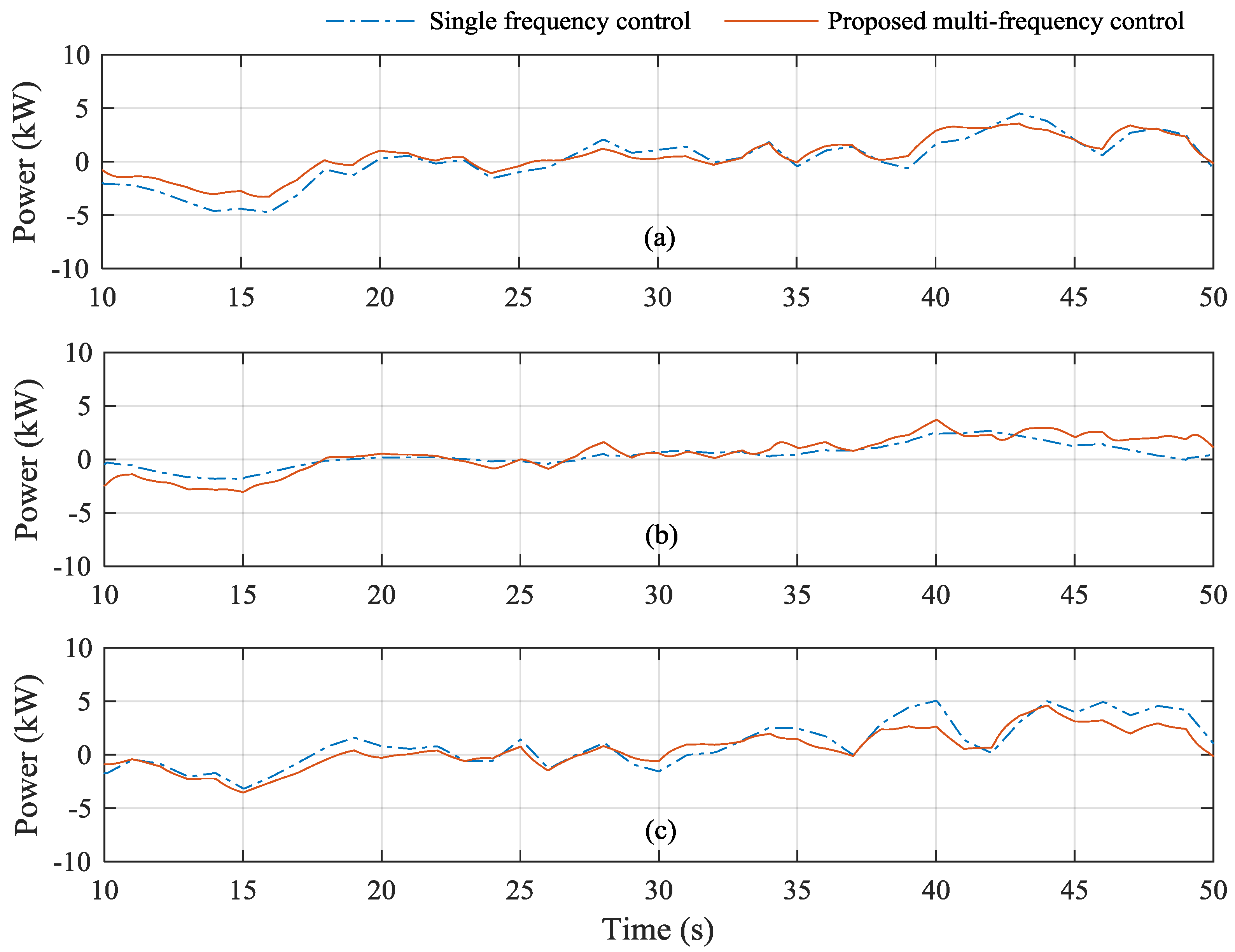
Figure 21.
Power sharing through the BTB converter: (a) BTB12; (b) BTB23.


Table 1.
System parameters.
| Components | Microgrid 1 | Microgrid 2 |
|---|---|---|
| System frequency | 50 Hz | 60 Hz |
| Maximum frequency deviation | 0.2 Hz | 0.2 Hz |
| System voltage | 380 V | 380 V |
| Nominal power of DG | 40 kW | 40 kW |
| Load | 20 kW | 20 kW |
© 2017 by the authors. Licensee MDPI, Basel, Switzerland. This article is an open access article distributed under the terms and conditions of the Creative Commons Attribution (CC BY) license (http://creativecommons.org/licenses/by/4.0/).
Share and Cite
MDPI and ACS Style
Yoo, H.-J.; Nguyen, T.-T.; Kim, H.-M. Multi-Frequency Control in a Stand-Alone Multi-Microgrid System Using a Back-To-Back Converter. Energies 2017, 10, 822. https://doi.org/10.3390/en10060822
AMA Style
Yoo H-J, Nguyen T-T, Kim H-M. Multi-Frequency Control in a Stand-Alone Multi-Microgrid System Using a Back-To-Back Converter. Energies. 2017; 10(6):822. https://doi.org/10.3390/en10060822
Chicago/Turabian StyleYoo, Hyeong-Jun, Thai-Thanh Nguyen, and Hak-Man Kim. 2017. "Multi-Frequency Control in a Stand-Alone Multi-Microgrid System Using a Back-To-Back Converter" Energies 10, no. 6: 822. https://doi.org/10.3390/en10060822
Note that from the first issue of 2016, this journal uses article numbers instead of page numbers. See further details here.