
Offshore Facilities to Produce Hydrogen

1
NAVANTIA, San Fernando-Puerto Real Shipyard, 11519 Puerto Real, Spain/Universidad Politécnica de Madrid, (ETSIN) Avda. Arco de la Victoria 4, 28040 Madrid, Spain
2
Universidad Politécnica de Madrid, (ETSIN) Avda. Arco de la Victoria 4, 28040 Madrid, Spain
*
Author to whom correspondence should be addressed.
Energies 2017, 10(6), 783; https://doi.org/10.3390/en10060783
Submission received: 3 April 2017
/
Revised: 22 May 2017
/
Accepted: 31 May 2017
/
Published: 6 June 2017
(This article belongs to the Special Issue Marine Energy)
Abstract
:As a result of international agreements on the reduction of CO2 emissions, new technologies using hydrogen are being developed. Hydrogen, despite being the most abundant element in Nature, cannot be found in its pure state. Water is one of the most abundant sources of hydrogen on the planet. The proposal here is to use energy from the sea in order to obtain hydrogen from water. If plants to obtain hydrogen were to be placed in the ocean, the impact of long submarines piping to the coast will be reduced. Further, this will open the way for the development of ships propelled by hydrogen. This paper discusses the feasibility of an offshore installation to obtain hydrogen from the sea, using ocean wave energy.
1. Introduction
Energy is responsible for causing 80% of European Union, EU, greenhouse gas (GHG) emissions and it is the root cause of climate change and air pollution. In addition, Europe depends more and more on the importation of hydrocarbons to fuel energy production. In this way, if the current conditions do not change, the EU will need to increase its energy imports from 50 to 65% by 2030, and the dependence on imported gas is expected to increase from 57% to 84% and on oil from 82% to 93% [1].
The challenge for climate and energy policies is to balance three objectives: assurance of energy supplies, competitive energy prices and decarbonisation [2] Taking into account that EU achieved an 18% reduction in GHG emissions by 2012, compared to 1990, and a 13% increase of final energy consumption came from renewable sources in 2011, the solution involves developing technologies to exploit renewable energy.
During the last few years, new technologies are being developed to generate energy in a clean, efficient and decentralized way, so that they do not pose a high cost to the environment [3]. In fact, research and commercial fuel cell start-up seems destined to be the way forward for high technology development during this century. It is expected that the installation and operation of these facilities, as well as the construction of applications, components, and systems will create in the near future numerous jobs with a high technological content [4].
A fuel cell can be defined as an electrochemical device that transforms, directly and continuously, the energy from the oxidation of hydrogen into electrical energy. Its operating principle is the opposite of that of electrolysis:
Hydrogen + Oxygen <=> Electricity + Water.
Hydrogen can be obtained in different ways, and ideally, the energy required to get it should come from a renewable source, thus providing a completely clean fuel. This paper discusses the feasibility of an offshore installation to obtain hydrogen from the sea, using the ocean wave energy to get the necessary electric energy. First, a review of hydrogen production is provided, followed by a summary of the different methods that exist today in order to produce the ocean energy that the hydrogen production installation requires. Finally, conclusions about the use of offshore facilities for electricity production are presented.
2. Hydrogen Production Facilities
Nowadays 96% of the produced hydrogen is obtained from fossil fuels and 95% of the production is consumed “in situ” [5]. The main methods to obtain hydrogen are as follows:
- (1)
- Reforming (with steam or oxygen): hydrogen is produced from hydrocarbons, mainly natural gas. The process takes place in two stages; in the initial phase the natural gas is converted into hydrogen, carbon dioxide and carbon monoxide. The second stage consists of producing additional hydrogen and carbon dioxide from the carbon monoxide obtained in the first stage. To do so, the carbon monoxide is treated with a high temperature steam current or oxygen:
- (2)
- Partial oxidation of fossil fuels with O2 default: a mixture of hydrogen is obtained, which is purified later on. The amounts of oxygen and water vapor are controlled so that the gasification continues without input of energy:
- (3)
- Water Electrolysis: passing electrical currents through the water to dissociate the water molecule into hydrogen and oxygen. The process is much more expensive than the use of steam reforming, but it produces high-purity hydrogen.
- (4)
- Photolysis: this procedure employs solar radiation through microorganisms or specific designed semiconductors to generate electrical power capable of producing water electrolysis.
- (5)
- Biomass gasification: it consists of making the biomass undergo a process of incomplete combustion between 700 °C and 1200 °C. The resulting product is a gas mainly composed of hydrogen, methane and carbon monoxide.
- (6)
- Pyrolysis: it consists of the incomplete combustion of biomass in the absence of oxygen to 500 °C. The result is charcoal and a gas mixture of carbon monoxide, carbon dioxide, hydrogen and light hydrocarbons.
- (7)
- Photobiological production: more than 400 varieties of primitive plants have been identified, such as green algae or cyanobacteria, by means of which hydrogen can be produced using only solar light, water and hydrogenase enzyme.
Of the above, the only ones that scarcely produce carbon dioxide by-products are photo-biological production, photolysis and hydrolysis. We have selected the last of these processes for this paper since the others are still in research stages, as shown in Table 1.
The main problem of obtaining hydrogen by hydrolysis compared to reforming is its high production costs. One way to reduce these costs is to increase the working temperature. The production of hydrogen from steam results in a decrease of the cost proportional to the temperature increase; at 1500 °K the production costs are 50% lower than the costs of the conventional process [7]. Although the total required energy of the process is increased, most of the additional heat energy required can be obtained from residual heat from other processes [8]. Table 2 shows the energy necessary to drive water electrolysis in different situations.
2.1. Seawater Electrolysis
Hydrolysis does not need a large amount of water to obtain significant amounts of hydrogen; two liters of water produce approximately a quantity of hydrogen with the power of one liter of gasoline [10]. There is also an inexhaustible source of raw materials in the water of the oceans.
The electrolytic process is as follows: a substance is dissolved in a given solvent, so that the ions constituting the substance are in the solution. Then an electrical current is applied to a pair of conductive electrodes placed inside the dissolution. The negative charged electrode, the cathode, attracts the positive ions or cations and the positive charged electrode, the anode, attracts the negative one, or anions. The energy required to separate the ions and increase their concentration around the electrodes comes from an electrical power source that keeps the potential difference between them. At the electrodes, electrons are absorbed or emitted by ions, concentrating the desired compound elements. Thus in the water electrolysis, hydrogen is formed at the cathode and oxygen at the anode.
2.2. Plant Design
Most hydrogen generators are alkaline, using a KOH solution (unipolar or bipolar), or polymer electrolyte membrane (PEM); the electrolyte is a conductive solid membrane.
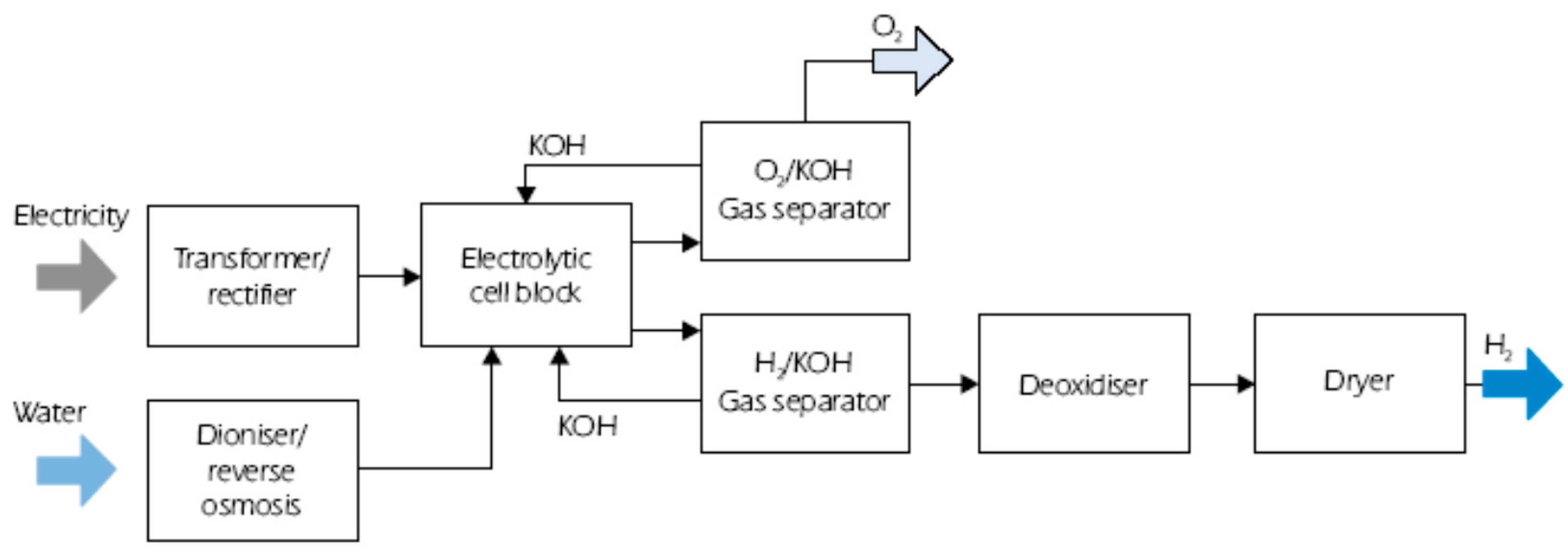
As it can be seen in Table 3 there are several types of hydrogen generators, but most of them are under investigation. In general, a hydrogen generator is composed of several electrolyte cells, manufactured in a modular form to facilitate assembly and disassembly. Its depiction appears in Figure 1.
Each cell has the following parts:
- Diaphragms for micro-filtration of gases. They must meet three main requirements: permeability to ions H3O+ and OH−, impermeability to H2 and O2 and resistance against the electrolyte under high pressure and temperature conditions. The diaphragm determines the purity of produced gases, the total performance of the hydrogen generator and facilitates the mechanical seal of the cells.
- Electrolytic medium, KOH solution.
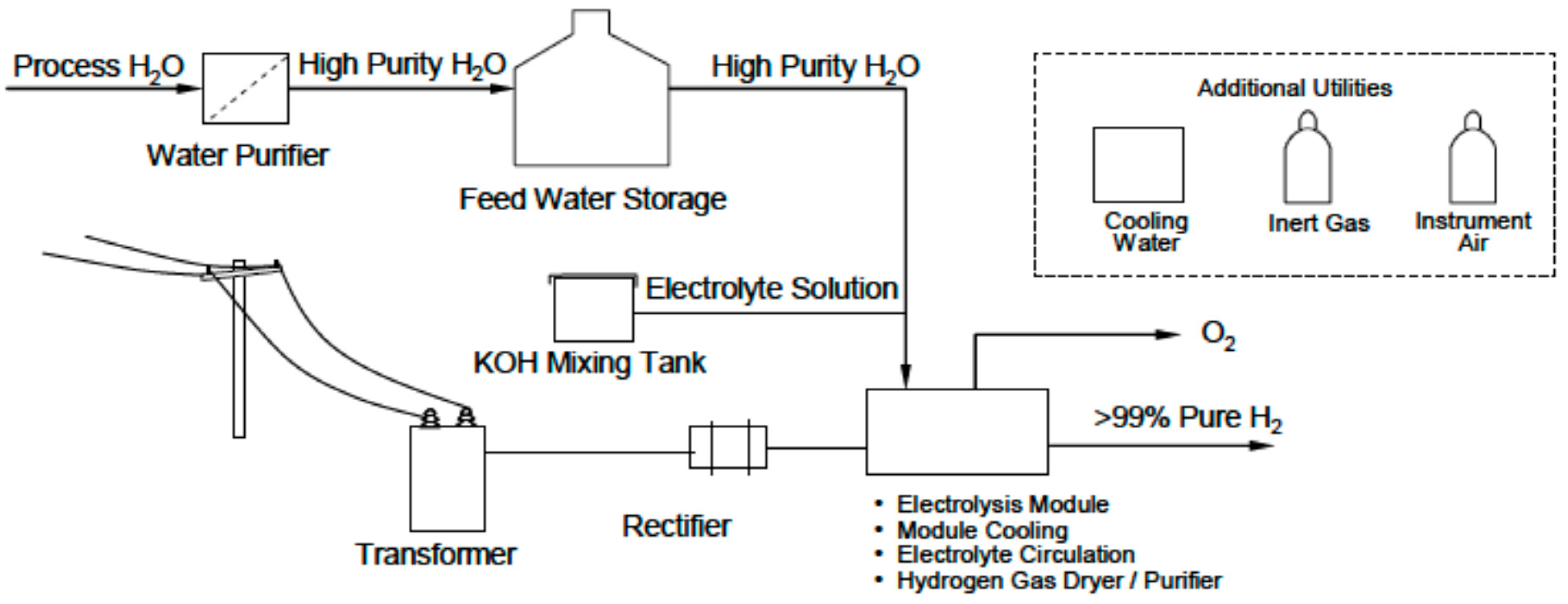
The typical requirements of a hydrolysis plant include electricity for electrolysis, water cooling for the hydrogen generating unit, pressurization and inert gas units and means for hydrogen storage [13], as shown in Figure 2.
It is important to highlight that hydrogen production using pressurized water requires less power than when hydrogen compressors are used. The difference is about 15% kW, which demonstrates the advantage of using water pressurized via pumps instead of power consuming compressors [14].
2.3. Storage and Transportation of Hydrogen
Due to its low density, hydrogen is a difficult gas to store. However there is a wide variety of possibilities for its storage so that the most appropriate technique for each application can be selected.
2.3.1. Gaseous Hydrogen Storage
The most conventional way to store hydrogen is in steel tanks or low pressure bottles (35 MPa) or high-pressure bottles (70 MPa) in order to reduce the volume they occupy. An alternative for the storage of hydrogen, for automotive applications, is by means of glass microspheres. The hydrogen charging process is done by taking advantage of the permeability of high pressure hydrogen (35–70 MPa) at a temperature of 300 °C which allows it to be introduced into the microspheres held within a pressure-resistant container. Once charging is complete, the unit cools down to ambient temperature with the gas being retained in the microspheres. Later on, for its proper use, it is necessary to heat the microspheres up to 200–300 °C, in order to release the hydrogen in a controlled way and feed the engine or fuel cell. The main problems presented by this technique are the low volumetric density of the hydrogen, the high filling pressures and the high release temperature of the hydrogen. However, they offer the advantage of being inherently safe because during transportation the hydrogen is at a low pressure and it allows use of non-spherical or cylindrical tanks. A storage density of 5.4% wt. is achieved [8].
2.3.2. Liquid Hydrogen Storage
Hydrogen can be stored in liquid form at cryogenic temperatures (−253 °C). The main advantage of this system is its high energy density per volume unit, even at relatively low pressures. Its main disadvantage is that there are evaporation losses during the periods in which it is not used if the containers are not adequately isolated and insulated. Another liquid storage system used is based on borohydride solutions. In this case, the hydrogen is released from a catalytic hydrolysis reaction:
NaBH4 (l) +2H2O (l) → 4H2 (g) +NaBO2 (s)
The theoretical storage density of this technique is 10.9% wt. [8].
2.3.3. Solid Hydrogen Storage
Solid storage is potentially safe and efficient, both for stationary and transportation applications. Three only three given groups of materials are considered suitable for this type of storage [8,15]:
(1) Materials based on carbon (nanotubes and graphite nanofibers)
Carbon nanotubes (CNT) are made of curved and closed hexagonal carbon nets, forming nanometric tubes of carbon with excellent properties. They are lightweight, hollow and porous with a high mechanical resistance. This system allows storage densities which are double that of the liquid hydrogen tanks. However this storage is possible only at −196 °C and when left at ambient temperature a large part of it evaporates.
(2) Rechargeable Hydrides:
Hydrogen has the property of reacting with different transition metals forming hydrides. The reactions are reversible under adequate conditions of pressure and temperature, therefore a certain mass of metal can be charged and discharged a virtually unlimited number of times and can be used as a solid storage tank of hydrogen. Almost all the hydrides operate at moderate pressures, there is no leakage and they allow purification of the hydrogen, which is released when heat is applied to materials and pressure is reduced. This type of storage is safe and easy to use and allows more hydrogen per volume unit to be stored than with liquid hydrogen. However the weight of the system is high as a result of the low hydrogen retention levels (<2.5% wt.).
(3) Chemical hydrides (reagents with H2O)
They can generate hydrogen by hydrolysis reactions.
2.3.4. Gaseous Hydrogen Transportation
Hydrogen gas is usually compressed in tanks at 20–70 MPa. Conventional compressed gas tanks, 20–35 MPa, are made of austenitic steel, and for higher pressures new composite materials of carbon fiber and polymer or aluminum reinforced with carbon fiber are being developed. These tanks can be transported by truck, rail or ship. Likewise, hydrogen pipe-transportation technology is commercially established, Germany has a gas pipeline with a length of 210 km working since 1939, it transports 8900 kg/h of hydrogen using a pipe with a diameter of 0.25 m and at a pressure of 2 MPa [16]. The pipelines used to transport hydrogen must have larger diameter than the current ones used for natural gas or an increased pressure to supply the same amount of energy. For equal-energy capacity of the transport line, the total cost of a gas-pipeline for hydrogen is in the order of six times more than that for natural gas [8].
2.3.5. Liquid Hydrogen Transportation
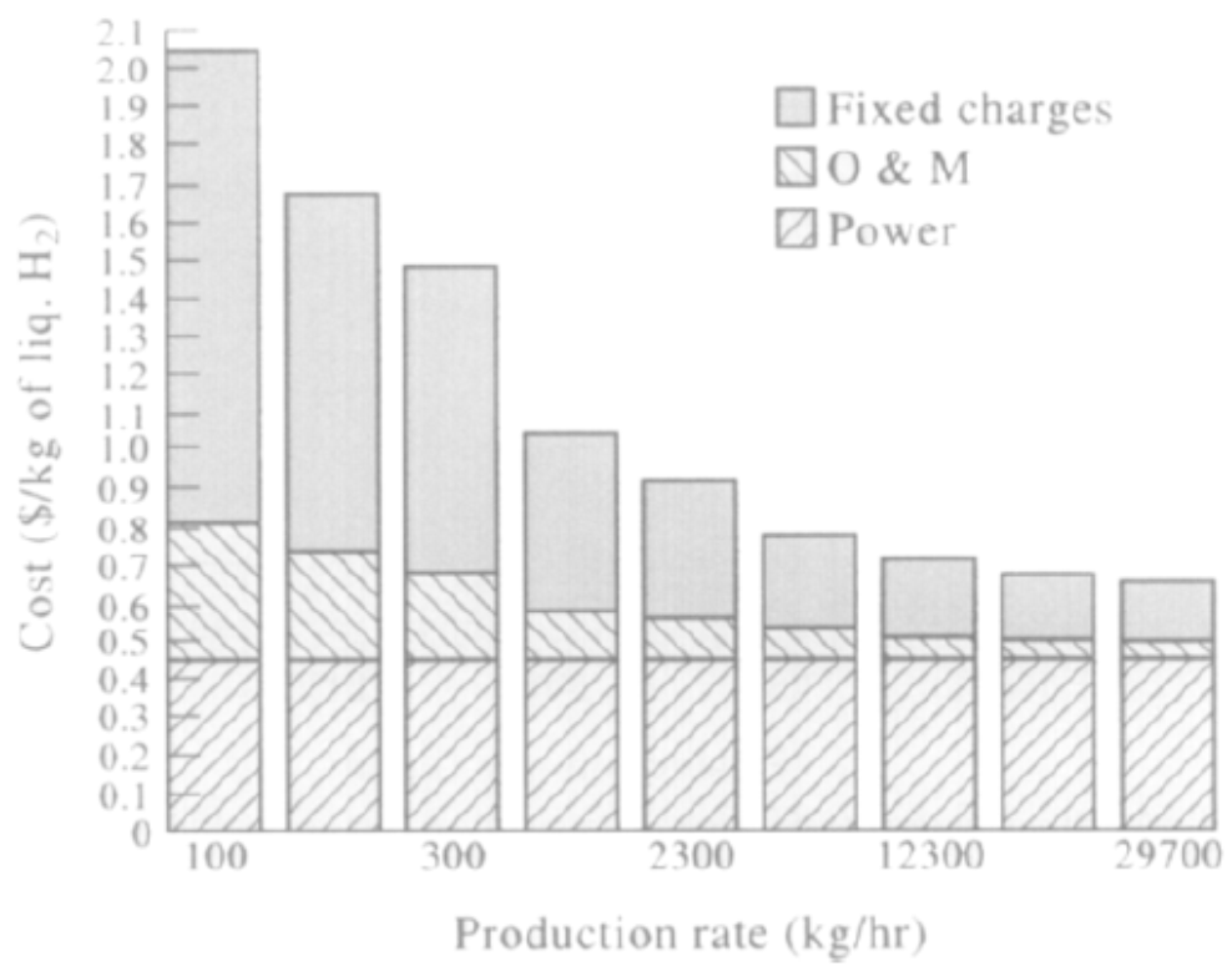
In the liquefaction process, a large amount of primary energy is consumed. However, as shown in Figure 3, this process offers a significant economy of scale, so that for above a determined production volume the option of blending can be adopted.
When transporting liquid hydrogen by truck or by ship over long distances, it is necessary to take into consideration that evaporative losses can reach amounts between 0.2% and 0.4% of the liquid hydrogen per day. In the case of transport by sea, fast ships would be required to limit the impact of these losses, or that the product could be recovered and used for the propulsion of the ship.
3. Possibility of Off-Shore Facilities
One of the determining factors for the viability of an off-shore hydrogen generation facility is that the electric power generator device provide sufficient power on-site for the exploitation of the off-shore plant. Table 5 shows the consumption of a medium off-shore unit.
This electric balance does not take into account the consumption of the equipment required for the generation and accumulation of hydrogen. According to National Renewable Energy Laboratory, NREL, [13] hydrolysis plants consume less than 50 KWh/Kg of the generated hydrogen, with an efficiency level of 67%. If we increase the pressure and/or temperature, we shall get better efficiency values, but for this article we will use the values stated in the table above. If we consider that the daily production of a theoretical hydrogen production facility would be 50,000 Kg/day [13], we would need a power of 104 MW. Therefore, for the offshore installation to be autonomous, it would need a device or set of them, capable of providing at least 105.21 MW.
4. Off-Shore Electrical Energy Production
Sea-waves have the greatest energy density of all renewable energy sources and, although it is highly variable, it is possible to forecast the waves at a certain point several days in advance. The power of the waves is usually measured using the standardize wave energy transport flux. The flux, in kilowatts per meter of crest length (kW/h) is given by:
where g denotes the acceleration caused by gravity, 9.8086 m/s2 and ρ denote the density of seawater, 1.025 kg/m3. Thus, periods between 7 s and 10 s and amplitudes of 3 m produce energy flows in the range of 40–50 KW/m [19,20]. Table 6 shows different equations used for the estimation of the energy flux (kW/m) from the waves.
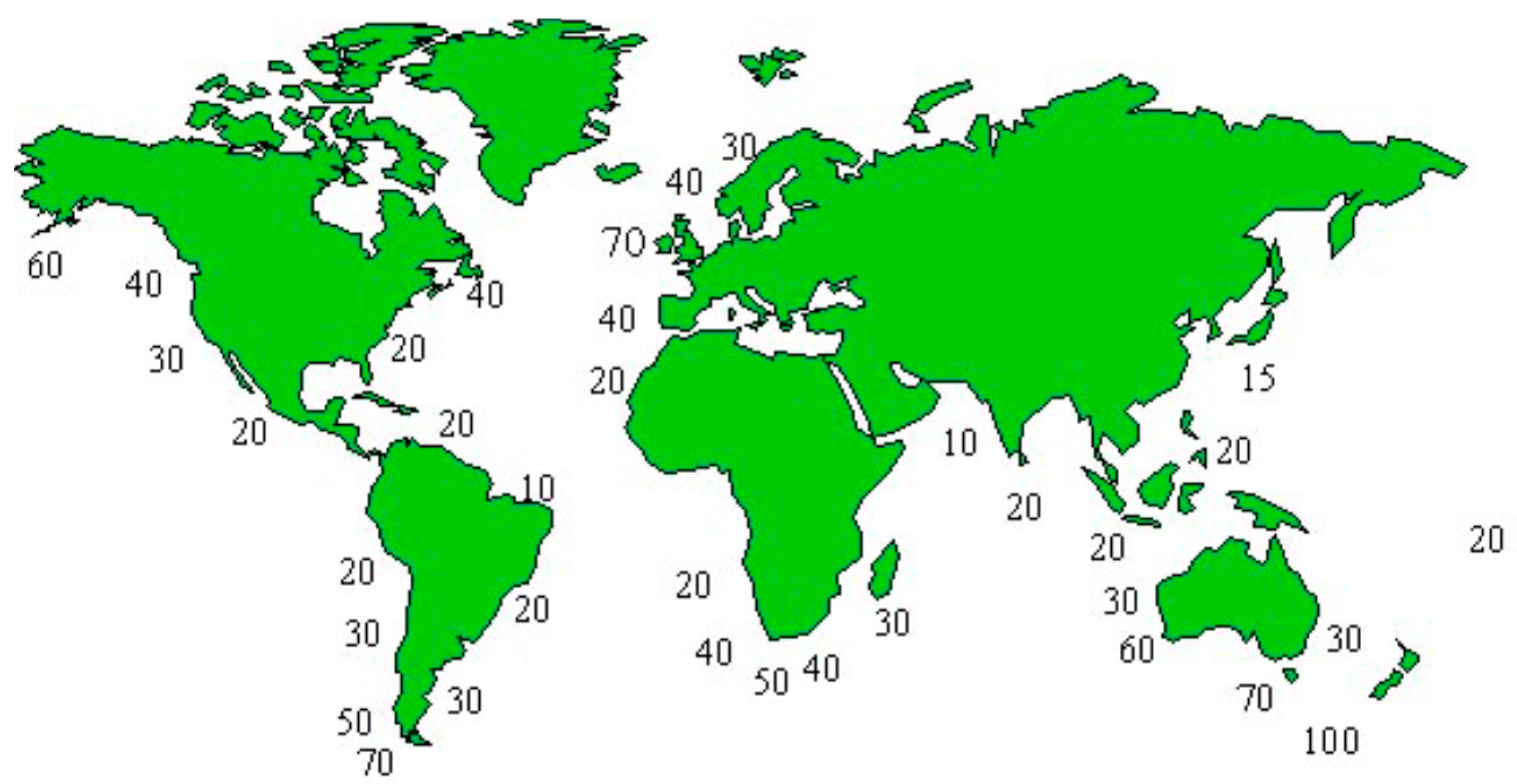
Wave energy is not evenly distributed throughout the planet, so most activity occurs between 30° and 60° of latitude in both hemispheres, induced by the prevailing westerly winds blowing in these regions. Figure 4 presents the wave energy distribution around the world.
Note that the waves lose energy when the depth decreases due to the friction between the particles of deep water and the seabed. This loss of energy implies a reduction of the useful energy that can be extracted from waves. The energy from the waves becomes electricity in two steps. It first becomes a combination of kinetic and potential energy by means of any of more than a thousand patented Wave Energy Converter (WEC) devices, which absorb the energy of the waves by a mechanical process; in the next step, the power absorbed by the mentioned device becomes electricity through air or water turbines, hydraulic oil systems or direct generators.
WEC devices are classified according to their relative position on the coast, to their capability to extract energy and by their geometry and relative position with respect to the waves. According to their relative position on the coast they can be classified as on-shore, close to the coast and off-shore.
According to their capability to extract energy they can be classified as low, medium or large capacity.
According to their geometry and relative position to the waves they can be classified as:
- Wave Activated Bodies (WAB), waves cause the body parts of a device to oscillate relative to each other, alternatively, the whole body may oscillate against a fixed reference. The oscillatory motion can be heave, pitch or roll. Hydraulic systems are generally employed to compress oil, air or water, which is then used to drive a generator. The main axis could be parallel to the front of waves or to the direction of the waves (attenuator).
- Oscillating Water Columns (OWC), it is like a caisson breakwater with a gap on the seaside face, which encloses a mass of water. Waves cause the water to rise and fall and this alternately compresses and decompresses an air column trapped inside. The energy is extracted from the oscillating air flow by using turbines.
- Overtopping Devices (OTD), use a sloping plate that leads the waves over the top of it into a reservoir located immediately behind it. The energy is extracted via turbines, using the difference in water levels between the reservoir and the average sea water level.
- Point Absorber (FP), it is a floating structure which absorbs energy from all directions through its movements at/near the water surface. It converts the motion of the buoyant top relative to the base into electrical power.
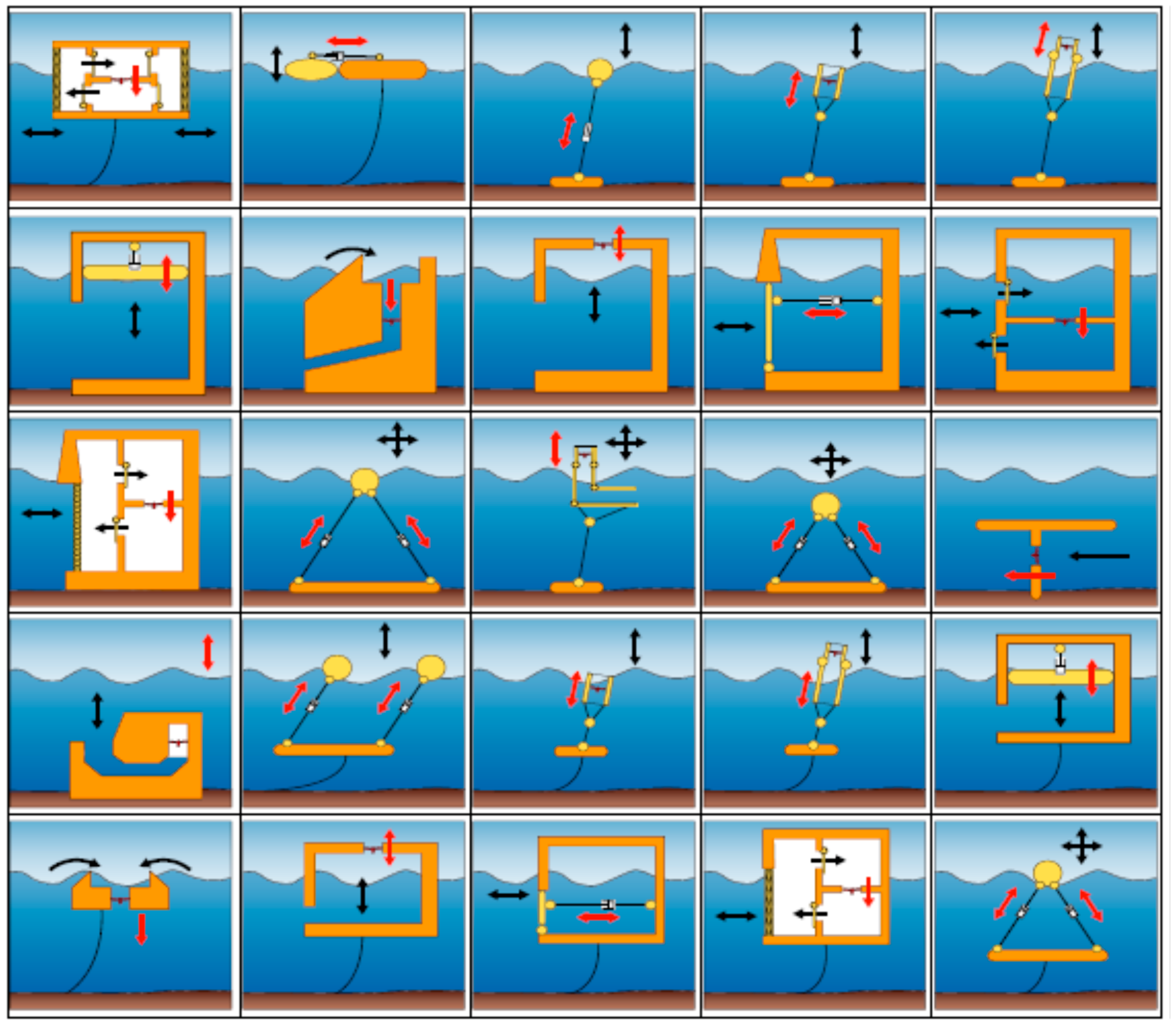
Figure 5 outlines schematically various devices according to their geometry and position relative to the waves.
Depending on the bathymetry and geology of the coast and the energy level of the waves at the place where the hydrogen generation plant will be installed, we shall select one type of WEC or another, and whether to use a single device or a farm. Table 7 shows the characteristics of several WECs.
In addition to the energy of the waves, ocean currents and tides are also energy vectors to be taken into account. For an effective use of tidal energy, the amplitude of the tide should be at least five meters and there should be a bay suitable for collecting and storing the water of the high tide.
Although tides are predictable and their supply is constant with a potential that does not vary significantly each year, the period during which energy can be generated is shorter than that of a conventional system, so it is necessary to invest in large facilities (Figure 6).
Dykes are built to take advantage of the tidal amplitude. They enclose bays to store water during high tide; it is retained there until low tide and then released through turbines during the intertidal hours using the potential energy caused by the slope between the dyke and the sea. The installation can be designed to harness the energy only during the emptying stage, operating in an elementary cycle of simple effect, or in both directions, operating according to an elementary cycle of double effect and it can have two-way turbines.
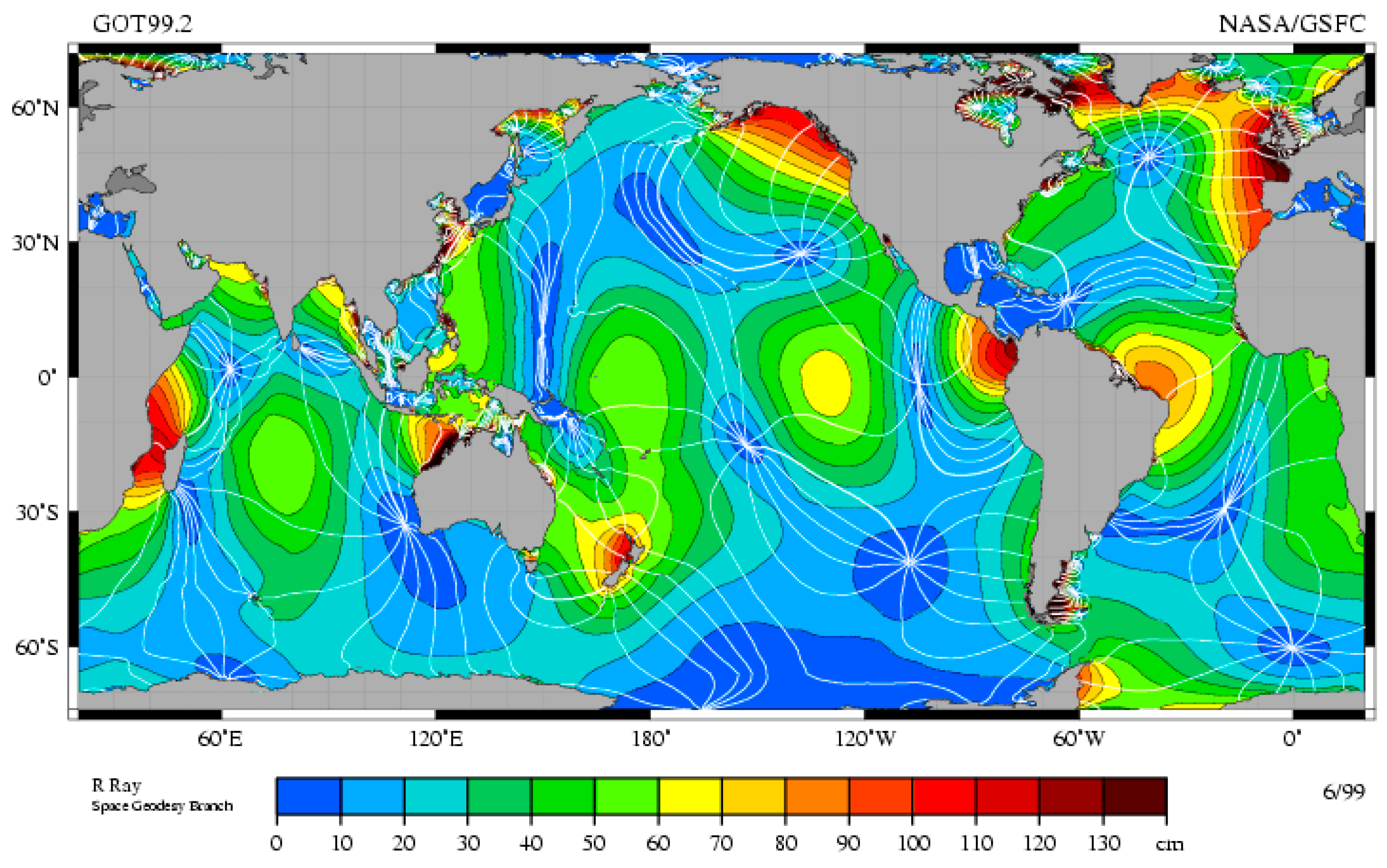
Finally, we must consider the ocean currents as a source of ocean energy. Currents are a surface movement of the oceans waters and they are composed of a horizontal movement produced by the wind and the inertia of the liquid mass to the Earth’s rotation and a vertical movement due to the centrifugal force of the Earth’s rotation. This movement is limited by the bathymetry of the seabed and the coasts, the difference in temperature between surface and deep waters, the effect of seasons and deviations of the currents due to the Coriolis effect (Figure 7). Currents can be classified according to several criteria, the most commonly used are:
- According to its temperature,
- ○
- Warm: surface water flow, has its origin in the inter-tropic zone and flows from the eastern coasts of the continents towards mid and high latitudes in opposite direction to the Earth’s rotation.
- ○
- Cold: cold water flow, moving as a result of the Earth’s rotation from the western coasts of the continents due to the rise of cold waters of great depths in the inter-tropic and sub-tropic zone.
- According to the phenomenon that generates the current,
- ○
- Oceanic: produced by the inertia of the Earth’s rotation; therefore they present a constant movement, in general, in E-W direction in the inter-tropic zone or in the opposite direction in the middle of high latitudes.
- ○
- Tide: they are superficial and periodic currents with daily cycle produced by the moon and the sun attraction.
- ○
- Wave: they are produced by winds, in particular, by storms and hurricanes associated with the movement of the air masses, both from the continent and from the sea.
- ○
- Longshore drift: resulting from the action of ocean currents reaching coasts which present some inclination or deviation from the original direction of the current.
- ○
- Density: it is due to the decrease in temperature (and increase in density) of the water mass as long as the depth is increased. Its effect is more pronounced in the straits.
- According to the depth:
- ○
- Impulsion: they are vertical movements generated below 1000 m in depth moving towards the surface to compensate the surface currents.
- ○
- Gradient or discharge: they are superficial horizontal movements generated by the Earth’s rotation and are affected by the prevailing winds. They are circular or spiral currents, turning right at latitudes close to the Tropic of Cancer, and turning to the left in the Tropic of Capricorn.
The advantage offered by the currents is their predictability and a capacity factor between 40% and 60% [20]. Maximum loads that will be borne can be accurately predictable, not so with WEC devices and they do not need supporting infrastructure since they can be moored to the seabed, floating in such a way that they are capable of aligning themselves to the current.
If they are used with a diffuser they can be designed to increase the pressure drop, recovering part of the pressure corresponding to the downstream speed. Devices that harness the energy of the currents are similar to wind turbines. In this case the turbine rotor is mounted on structures moored at the bottom or suspended from a float. (Figure 8 and Figure 9) [20].
The power we can obtain from the currents is a function of the turbine diameter and the current speed. Nowadays current speed must be over 3 knots in order to be usable, and between 2 and 4 m/s to be profitable.
Another type of technology that is being developed for the use of the marine currents consists of sliding airboats. The airboat is coupled to a swing-arm whose movement is caused by the lifting thrust of the current over a wing-like surface. This motion pumps a hydraulic fluid into a turbine to generate electricity [24].
5. Conclusions
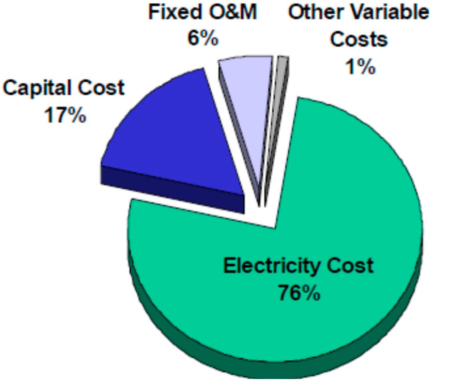
One of the main factors influencing the generation of hydrogen is the cost of the electricity used in its generation, almost 80% of the total costs [13], as shown in Figure 10. Reducing the cost of electricity by using renewable energies would allow the competitive use of hydrogen as a fuel for the automotive industry amongst others. Off-shore hydrogen production and supply facilities would facilitate the development of fuel cells for ships, submarines and Unmanned Undersea Vehicle (UUV) propulsion, reducing sea shipment costs and the risk of contamination by fuel spills as well as CO2 emissions into the atmosphere [25].
In addition these facilities would serve as a lever for research on floating structures for ocean energy use, promoting the development and diversification of the shipbuilding industry in areas where they would be deployed.
Furthermore, taking into account that the increase of the global population shall be nearly 34% by 2050 with many of them living close to the coast in non-OECD (Organization for Economic Co-operation and Development) countries, which are presently under-developed, there will exist the opportunity to utilize new energy infrastructures. These countries will be interested in the use of WEC that allows their independence of importing fossil fuels from other countries and produce electricity with fuel cells thus reducing the imports costs and the costs of the transport of the electricity.
National governments use many policy instruments to ensure and enable investments in ocean energy technologies. Not only investing directly in R&D but encouraging and supporting the contribution from public and private investors. The goal of all these policies is to reduce the world energy sector’s carbon emissions, whilst minimizing impacts on marine environments [26].
Author Contributions
Pilar Blanco-Fernández designed the paper, took care of the literature review, provided the background and filtered the results and Francisco Pérez-Arribas supervised the paper writing
Conflicts of Interest
The authors declare no conflict of interest
References
- Commission of the European Communities. Communication from the Commission to the European Council and the European Parliament, an Energy Policy for Europe; European Commission: Brussels, Belgium, 2007. [Google Scholar]
- Erbach, G. EU Climate and Energy Poicies Post-2020. Available online: http://www.europarl.europa.eu/RegData/bibliotheque/briefing/2014/130681/LDM_BRI(2014)130681_REV1_EN.pdf (acceseed on 2 April 2017).
- Haug, M. Public Support to Hydrogen and Fuel Cells: An International Perspective; International Energy Agency IEA: Virginia, WA, USA, 2004. [Google Scholar]
- International Energy Agency. Clean Energy, Progress Report; Organization for Economic Co-operation and Development/International Energy Agency (OECD/IEA): Paris, France, 2011. [Google Scholar]
- González, A. The Hydrogen economy, why and what for. La economía del Hidrógeno, Por qué y para qué. 16 June 2007. Available online: http://docplayer.es/21748924-La-economia-del-hidrogeno.html (accessed on 2 April 2017).
- Escapa, A. Hydrogen Production Simultaneously to the Purification of Residual Waters by Means of Biocatalytic Electrolysis; Instituto de Medio Ambiente, Recursos Naturales y Biodiversidad: León, Spain, 2011. [Google Scholar]
- Fierro, J.L. lychnos. Cuadernos de la Fundación General CSIC. Available online: http://www.fgcsic.es/lychnos/es_es/articulos/hidrogeno_metodologias_de_produccion (accessed on 20 March 2017).
- González, A. Production, storage and Hydrogen distribution. Producción, Almacenamiento y Distribución de hidrógeno. Available online: http://hrudnick.sitios.ing.uc.cl/alumno14/hidrog/trans-almac-dist.htm (accessed on 2 April 2017).
- Prince-Richard, S. A Techno-Economic Analysis of Decentralized Electrolytic Hydrogen Production for Fuel Cell Vehicles; University of Victoria: Victoria, BC, Canada, 2004. [Google Scholar]
- Schatz Energy Research Center (SERC). Humboldt State University. Available online: http://www.schatzlab.org/spanish/h2fuel.html (accessed on 15 March 2017).
- González, A. El Hidrógeno Como Vector Energético y las Pilar de Combustible; Instituto Nacional de Técnica Aeroespacial (INTA): Madrid, Spain, 2013. [Google Scholar]
- Conde, E.; Reyes, E. Production and Storage of Hydrogen. Producción y Almacenaje de Hidrógeno. Available online: http://ingenieros.es/files/proyectos/Produccion_y_alamcenaje_hidrogeno.pdf (accessed on 2 April 2017).
- Genovese, J. Current State-of-the-Art Hydrogen Production Cost Estimate Using Water Electrolysis; National Renewable Energy Laboratory: Golden, CO, USA, 2009. [Google Scholar]
- Laoun, B. Thermodynamics aspect of high pressure hydrogen production by water electrolysis. Revue Energies Renouv. 2007, 10, 435–444. [Google Scholar]
- Hirscher, M. State of the Art and Trends in Material Development for Hydrogen Storage; Asociación Española del Hidrógeno: Sevilla, Spain, 2014. [Google Scholar]
- Fernández-Bolaños, C. Hydrogen distribution. Energética del hidrógeno. Contexto, Estado Actual y Perspectivas de Futuro. 3.3 Distribución del hidrógeno. Sevilla, E.T.S.I. 2005. Available online: http://bibing.us.es/proyectos/abreproy/3823/ (accessed on 3 April 2017).
- Syed, M.T.; Sherif, S.A.; Veziroglu, T.N.; Sheffield, J.W. An economic analysis of three hydrogen liquefaction systems. Int. J. Hydrogen Energy 1998, 23, 565–576. [Google Scholar] [CrossRef]
- Sustainable Energy. Energía Sostenible. Available online: http://www.energiasostenible.net/almacenamiento_y_transporte_de_hidrog.htm (accessed on 20 March 2017).
- Calero, R.; Carta, J.A.; Padrón, J.M. Wave Energy. Energía; Energía del Oleaje; Ayuntamiento de las Palmas: Las Palmas, Spain, 2000. [Google Scholar]
- Fernández, P. Biblioteca Sobre Ingeniería Energética. Available online: http://files.pfernandezdiez.es/EnergiasAlternativas/mar/PDFs/02Corrientes.pdf (accessed on 20 March 2017).
- Cavia del Olmo, B. Exploitation of the wave energy potential depending on the range of work of prototype devices. In Explotación del Potencial de Energía del Oleaje en Función del Rango de Trabajo de Prototipos Captadores; Universidad Politécnica de Cataluña: Barcelona, Spain, 2009. [Google Scholar]
- NASA Scientific Visualization. Available online: https://svs.gsfc.nasa.gov//stories/topex/tides.html (accessed on 17 March 2017).
- NASA Ocean Motion. Available online: http://oceanmotion.org/global-surface-currents.htm (accessed on 17 March 2017).
- Agencia Andaluza de la Energía. Andalucía Energy Agency (Agencia Andaluza de la Energía; Consejería De Economía, Innovación, Ciencia Y Empleo). Available online: https://www.agenciaandaluzadelaenergia.es/es/documentacion/tipo-de-documento/informes-y-estudios/recursos-de-energias-marinas-en-andalucia-fase-ii (accessed on 23 March 2017).
- Carrillo, F. Hydrogen, a Unique Chemical Element; UCLM: Puertollano, Spain, 2007. [Google Scholar]
- Ocean Energy Systems. An International Vision for Ocean Energy 2017; Ocean Energy Systems OES: Lisbon, Portugal, 2017. [Google Scholar]
Figure 1.
Diagram of an alkaline electrolyze [12].
Figure 1.
Diagram of an alkaline electrolyze [12].

Figure 2.
Electrolysis process flow diagrams [13].
Figure 2.
Electrolysis process flow diagrams [13].

Figure 3.
Cost of power, operation and maintenance and fixed charges on capital investment of an optimized large-scale hydrogen liquefier [17].
Figure 3.
Cost of power, operation and maintenance and fixed charges on capital investment of an optimized large-scale hydrogen liquefier [17].

Figure 4.
Distribution of wave energy in deep waters in kW/m of ridge length [19].
Figure 4.
Distribution of wave energy in deep waters in kW/m of ridge length [19].

Figure 5.
Different devices to extract energy from the waves [19].
Figure 5.
Different devices to extract energy from the waves [19].

Figure 6.
Global map of tidal amplitude [22].
Figure 6.
Global map of tidal amplitude [22].

Figure 7.
Main global current [23].
Figure 7.
Main global current [23].
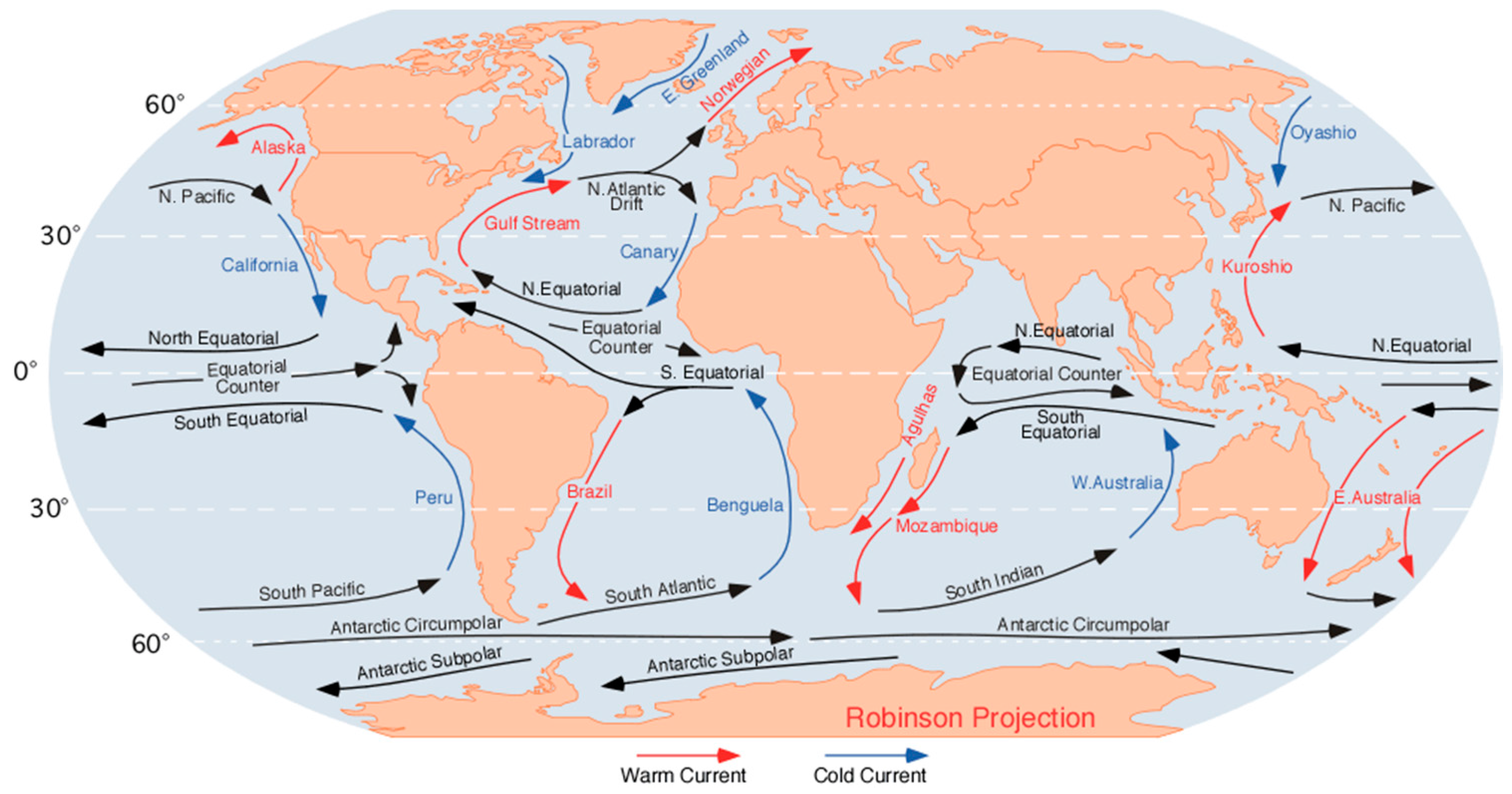
Figure 8.
Marine current devices, axial rotor and cross flow.

Figure 9.
Marine current devices, supports.
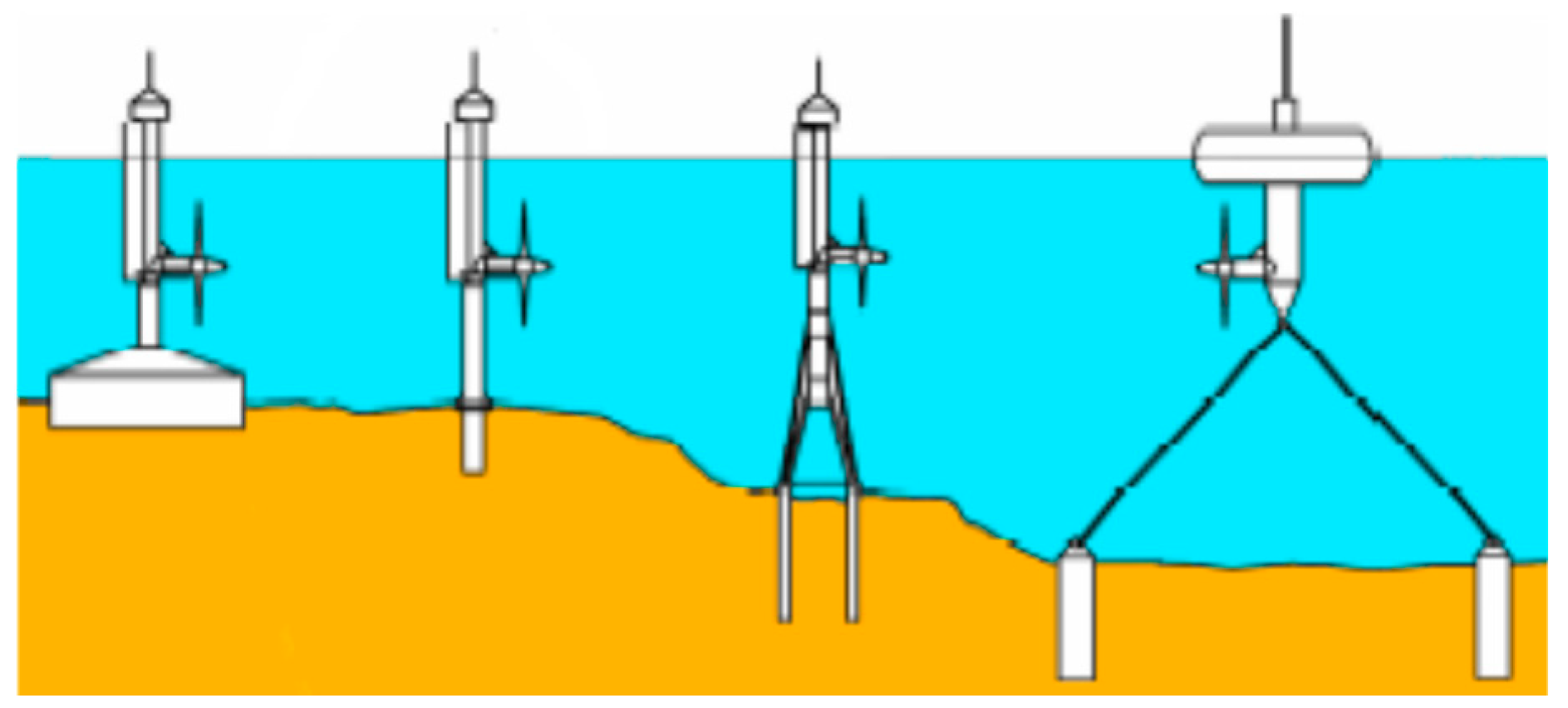
Figure 10.
Hydrogen Production, cost breakdown.


Table 1.
Comparison between different technologies of hydrogen production [6].
Table 1.
Comparison between different technologies of hydrogen production [6].
| Technology | Substratum | Efficiency | Availability | CO2 Emissions |
|---|---|---|---|---|
| Reforming | Hydrocarbons | 70%–85% | Commercial | High |
| Partial Oxidation | Hydrocarbons | 60%–75% | Commercial | High |
| Auto-heat Reforming | Hydrocarbons | 60%–75% | Short term | High |
| Plasma Reforming | Hydrocarbons | 9%–85% | Long term | High |
| Biomass gasification | Biomass | 35%–50% | Commercial | Mid |
| Photolysis | Water | 0.5% | Long term | Null |
| Dark fermentation | Biomass | 60%–80% | Long term | Null-Low |
| Photo fermentation | Biomass | 0.1% | Long term | Null-Low |
| Electrolysis biocatalyst | Biomass | 78% | Long term | Null-Low s |
| Alkaline Electrolysis | Water | 50–60% | Commercial | Mid |
| PEM Electrolysis | Water | 55–70% | Short term | Mid |
| Solid Oxides (SOFC) Electrolysis | Water | 40–60% | Medium-term | Mid-High |
| Water heat-lysis | Water | − | Long term | Mid-High |
| Photo-electrochemical water lysis | Water | 12.4% | Long term | Null |
Table 2.
Theoretical energy use of water electrolysis as a function of pressure and temperature, based on reversible voltage Erev, thermoneutral voltage Etn and higher-heating-value voltage EHHV (assuming current efficiency of 100%) [9].
Table 2.
Theoretical energy use of water electrolysis as a function of pressure and temperature, based on reversible voltage Erev, thermoneutral voltage Etn and higher-heating-value voltage EHHV (assuming current efficiency of 100%) [9].
| Pressure | Temperature | Single-Cell Voltage | Theoretical Energy Use | |
|---|---|---|---|---|
| bar | °C | Volt | kWh/Nm3·H2 | kWh/kg·H2 |
| 1 | 25 | Erev = 1.229 | 2.94 | 32.7 |
| Etn = 1.481 | 3.54 | 39.4 | ||
| EHHV = 1.481 | 3.54 | 39.4 | ||
| 1 | 1000 | Erev = 0.922 | 2.10 | 24.5 |
| Etn = 1.292 | 3.02 | 34.4 | ||
| EHHV = 1.714 | 4.10 | 45.6 | ||
| 400 | 25 | Erev = 1.344 | 3.21 | 35.7 |
| Etn = 1.596 | 3.81 | 42.4 | ||
| EHHV = 1.596 | 3.81 | 42.4 | ||
Table 3.
Fuel cell types [11].
Table 3.
Fuel cell types [11].
| Technology | Operation T (°C) | Fuel | Performance | Power |
|---|---|---|---|---|
| Alkaline (AFC) | 80–100 | H2 | 60 | 5–150 KW |
| Polymer (PEM) | 70–80 | H2 pure or from the reforming of hydrogenated compounds | 40–50 | 5–250 KW |
| Direct Methanol (DMFC) | 50–100 | Dilute methanol | 30–40 | 0.01–0.2 |
| Phosphoric Acid (PAFC) | 200–220 | H2 from the reforming of GN or methanol | 40–50 | 50 KW–2 MW |
| Carbonates (MCFC) | 600–650 | H2 and CO from the internal reforming of natural gas or coal gasification | 45–60 | 100KW–2 MW |
| Solid Oxides (SOFC) | 800–1000 | 50–65 | 100–250 KW |
Table 4.
Characteristics of Hydrogen storage methods.
| Technology | Volume (L) | Mass (Kg) | Density (%H2 by Weight) |
|---|---|---|---|
| 35 MPa, H2 compressed | 145 | 45 | 6.7 |
| 70 MPa, H2 compressed | 100 | 50 | 6.0 |
| Cryogenic, H2 liquid | 90 | 40 | 7.5 |
| Metal hydrides, H2 solid | 55 | 215 | 1.4 |
Table 5.
Average power consumption of an off-shore platform.
| Service | Normal Operation | Emergency |
|---|---|---|
| kW | kW | |
| Ballast | 145.00 | 0.00 |
| Accommodation | 84.40 | 20.00 |
| Air | 28.00 | 0.00 |
| Cooling | 254.00 | 0.00 |
| Miscellaneous | 39.60 | 0.00 |
| Services | 383.60 | 0.00 |
| Ventilation-A/C | 105.00 | 0.00 |
Table 6.
Summary of wave energy equations depending on the model selected [21].
Table 6.
Summary of wave energy equations depending on the model selected [21].
| Model | Distribution | Flux (kW/m) | |
|---|---|---|---|
| Pierson-Moskowitz | |||
| Bretshneider-Mitsuyasu | |||
| Jonswap | |||
| ISSC |
Table 7.
Main features of WECs.
| Name | Type | Power (kW) | Used Surface (m2) | Ratio Approx. Power/Surface (×103) | Efficiency | Fluid | Place |
|---|---|---|---|---|---|---|---|
| Alda | OWC | 1000 | - | - | Air | On-Shore | |
| Aquabuoy | FP | 500 | 157 | 3183 | 40% | sea water | Off-Shore |
| AWS | FP | 1200 | 90 | 13,296 | Air | Near Shore | |
| Cockerell | WAB | 2000 | 5000 | 400 | pressure oil | Off-Shore | |
| BBDB | OWC | 200 | 36 | 5556 | 35% | Air | Near Shore |
| Breakwave | OWC | 750 | 525 | 1427 | Air | On-Shore | |
| Ship Kaimei | WAB | 2000 | 960 | 2083 | <10% | Air | Off-Shore |
| Cylinder of Bristol | WAB | 2,000,000 | 1,656,000 | 1208 | sea water | Off-Shore | |
| Clam | OWC | 2500 | 2827 | 884 | Air | Off-Shore | |
| Converter of Belfast | OWC | 75 | 51 | 1471 | Air | On-Shore | |
| Unión Fenosa | OWC | 27 | 48 | 559 | sea water | On-Shore | |
| El Pato Salter | WAB | 2310 | 4050 | 570 | 90% | pressure oil | Off-Shore |
| in China | OWC | 30 | 40 | 750 | 10–35% | Air | On-Shore |
| in Kujukuri | OWC | 30 | 31 | 955 | Air | On-Shore | |
| in Pico | OWC | 500 | 96 | 4167 | 54% | Air | On-Shore |
| Energetech | OWC | 500 | 875 | 571 | Air | On-Shore | |
| Kvaerner | OWC | 600 | 79 | 6366 | Air | On-Shore | |
| Limpet | OWC | 500 | 84 | 5952 | Air | On-Shore | |
| Migthy Wale | OWC | 110 | 1200 | 92 | 54% | Air | Near Shore |
| Multiwave Plane | OTD | 30 | 22 | 1374 | sea water | Near Shore | |
| NEL | OWC | 2,000,000 | 1,552,000 | 1289 | 46% | Air | Off-Shore |
| Nereida | OWC | 250 | 700 | 537 | Air | On-Shore | |
| Oyster | WAB | 500 | 216 | 2315 | sea water | Near Shore | |
| Pelamis | WAB | 750 | 490 | 118 | 72% | pressure oil | Off-Shore |
| PowerBuoy | FP | 20 | 20 | 1531 | pressure oil | Off-Shore | |
| Sakata | OWC | 60 | 360 | 167 | 18% | Air | On-Shore |
| Searev | FP | 500 | 375 | 1333 | pressure oil | Off-Shore | |
| SSG | OTD | 12,000 | 75,000 | 1944 | 50% | sea water | Everywhere |
| Tapchan | OTD | 400 | 7000 | 57 | 33% | sea water | On-Shore |
| Wavebob | FP | 1500 | 225 | 6667 | pressure oil | Off-Shore | |
| Wavedragon | OTD | 6000 | 51,000 | 160 | 81% | sea water | Off-Shore |
| Waveroller | WAB | 13 | 16 | 825 | pressure oil | Near Shore | |
| Wavestar | Multy FP | 6000 | 1440 | 4167 | pressure oil | Near Shore |
© 2017 by the authors. Licensee MDPI, Basel, Switzerland. This article is an open access article distributed under the terms and conditions of the Creative Commons Attribution (CC BY) license (http://creativecommons.org/licenses/by/4.0/).
Share and Cite
MDPI and ACS Style
Blanco-Fernández, P.; Pérez-Arribas, F. Offshore Facilities to Produce Hydrogen. Energies 2017, 10, 783. https://doi.org/10.3390/en10060783
AMA Style
Blanco-Fernández P, Pérez-Arribas F. Offshore Facilities to Produce Hydrogen. Energies. 2017; 10(6):783. https://doi.org/10.3390/en10060783
Chicago/Turabian StyleBlanco-Fernández, Pilar, and Francisco Pérez-Arribas. 2017. "Offshore Facilities to Produce Hydrogen" Energies 10, no. 6: 783. https://doi.org/10.3390/en10060783
Note that from the first issue of 2016, this journal uses article numbers instead of page numbers. See further details here.