
Influence of Stratigraphic Conditions on the Deformation Characteristics of Oil/Gas Wells Piercing Longwall Pillars and Mining Optimization


Abstract
:1. Introduction
2. Background and Methodology
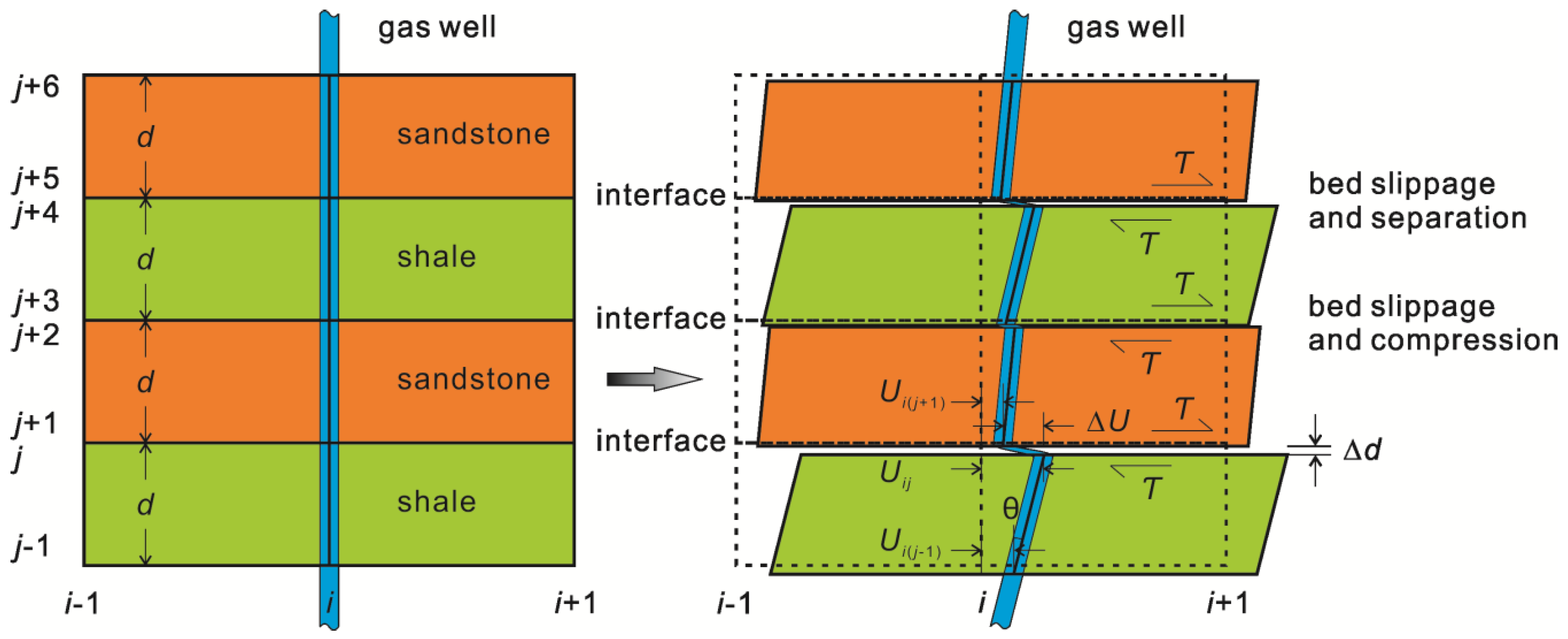
2.1. Strata and Well Deformation
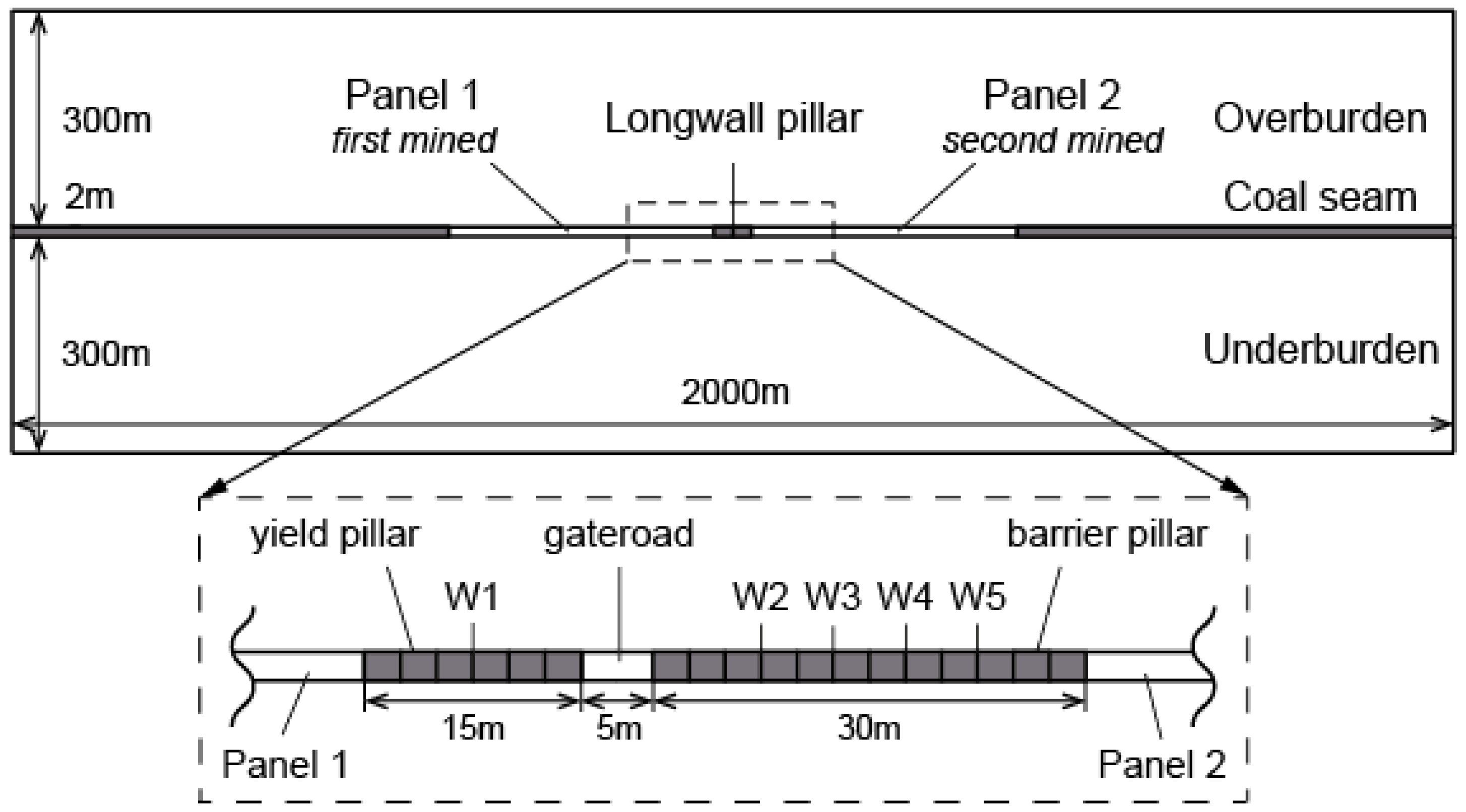
2.2. Geological Setting and Mining Parameters
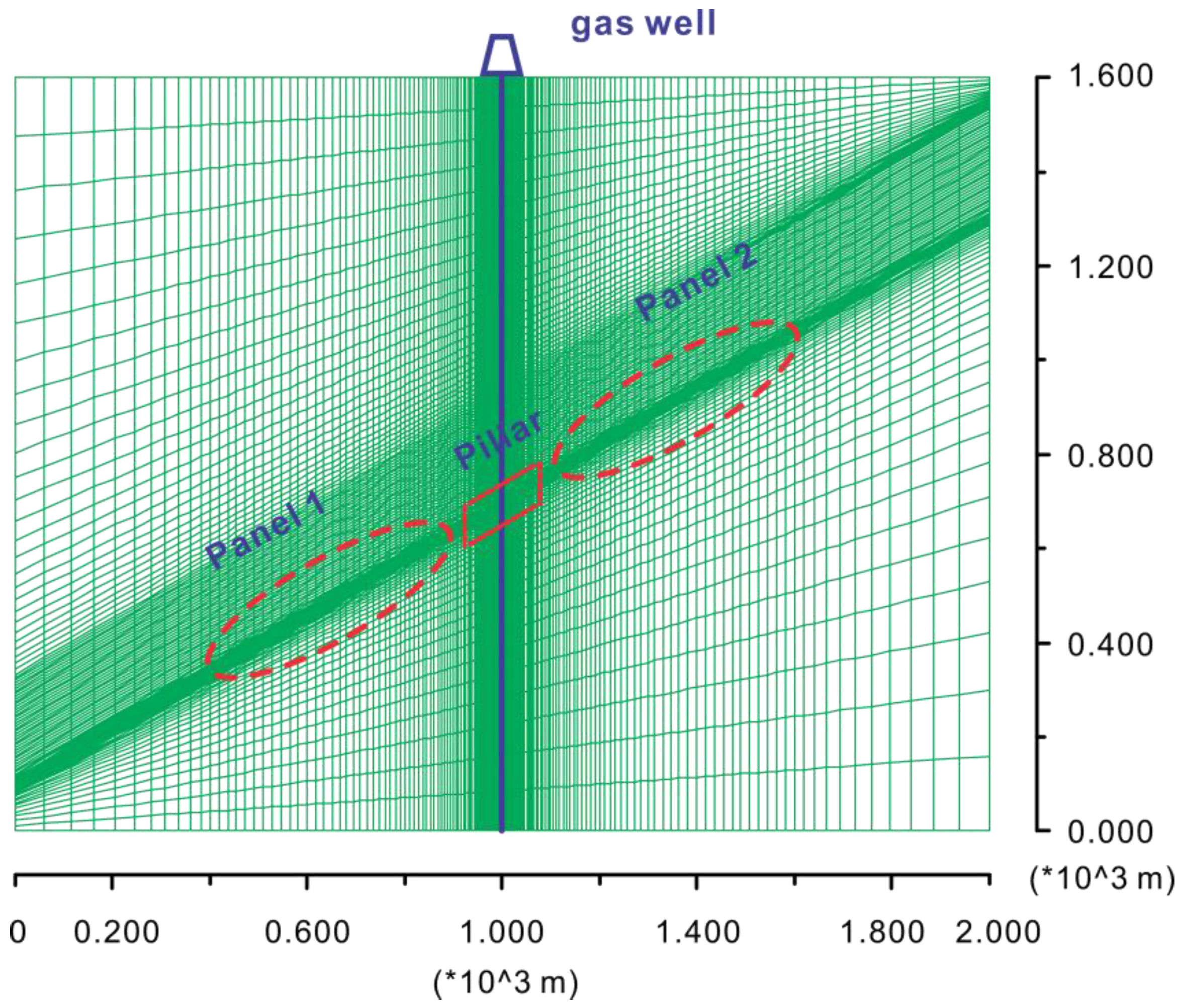
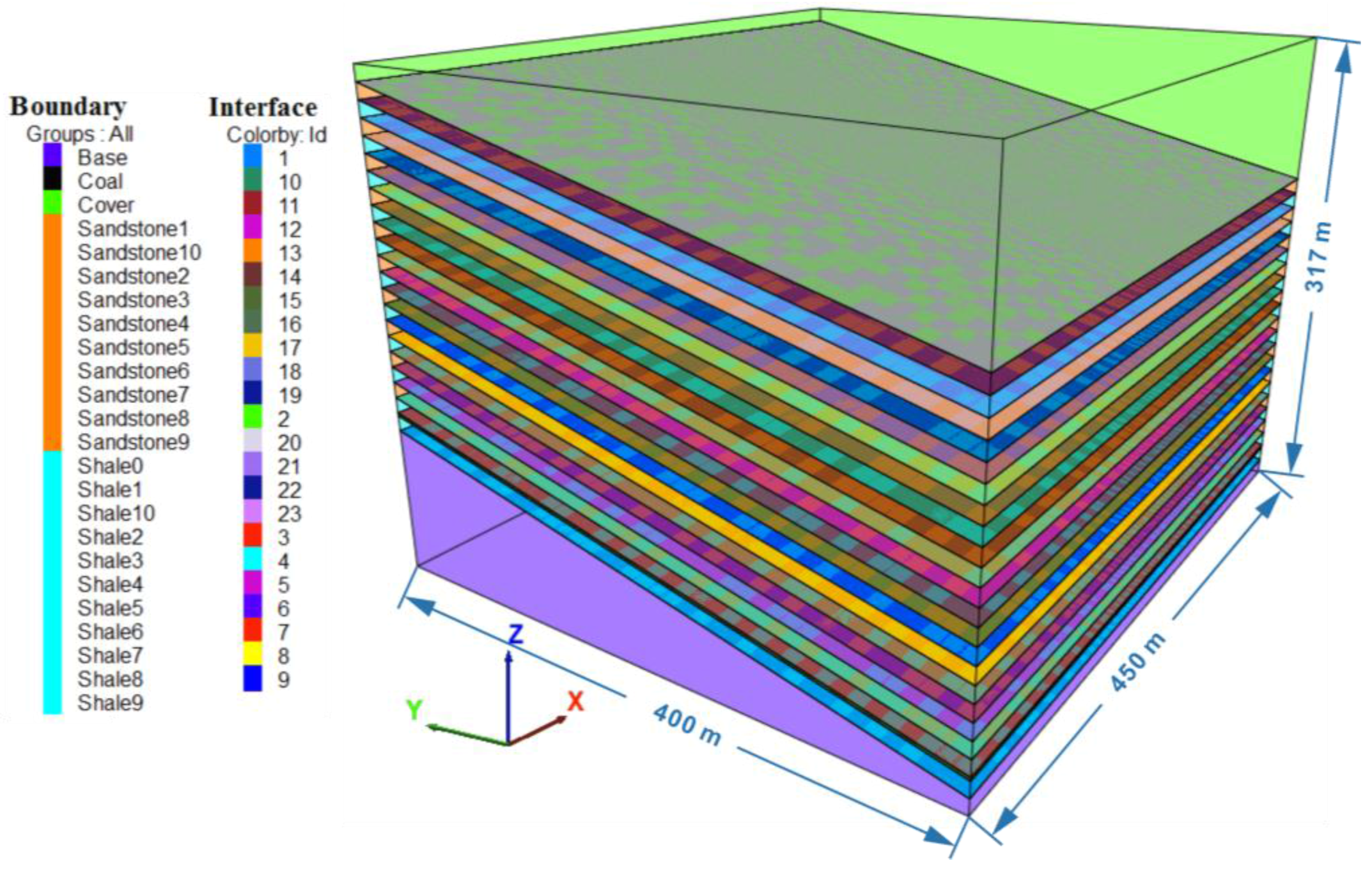
2.3. Model
3. Analysis of Model Results
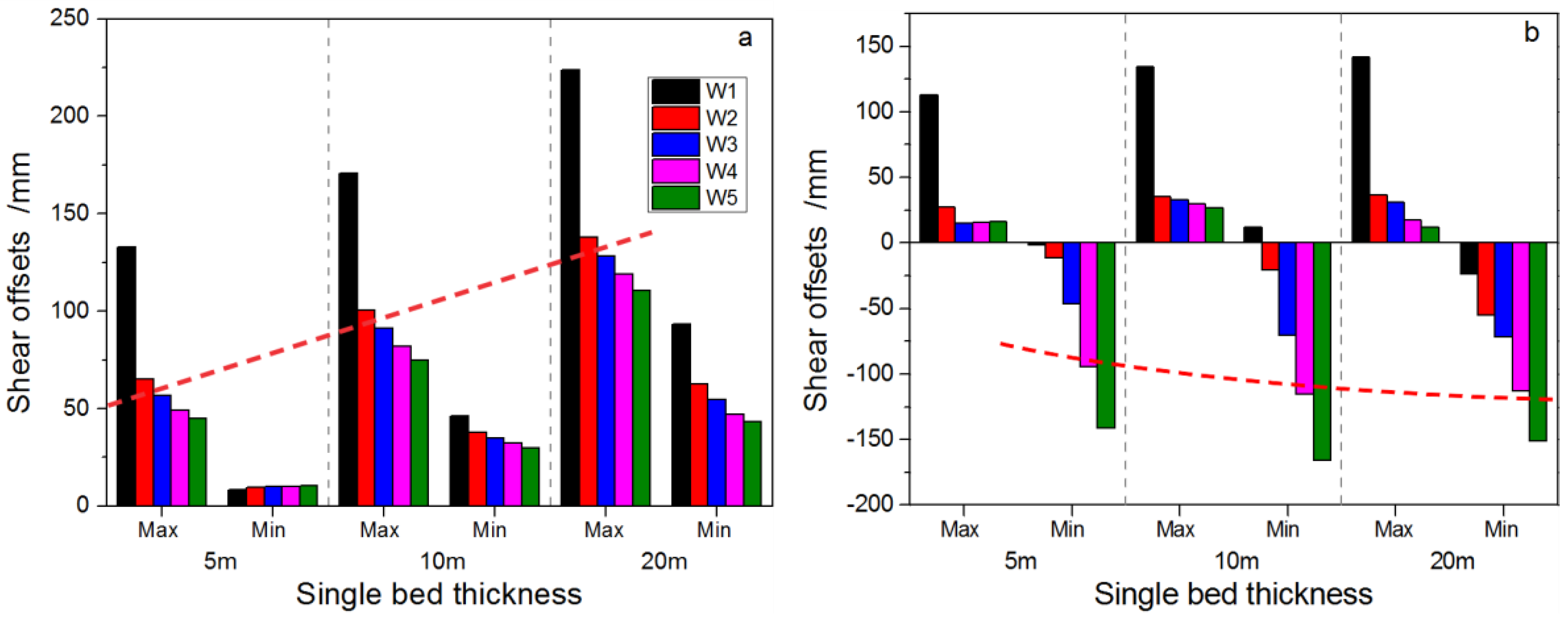
3.1. Influence of Single Rock Layer Thickness (SRLT)
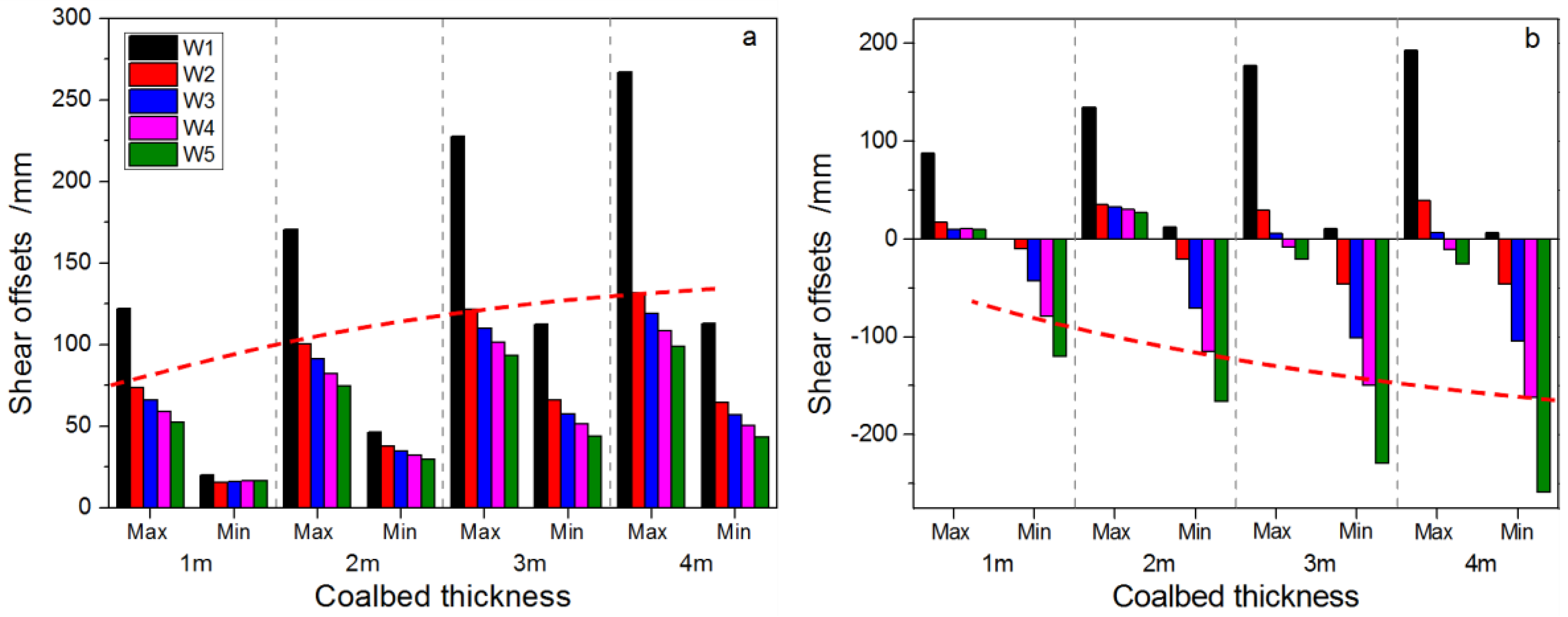
3.2. Influence of Seam Mining Height (SMH)
3.3. Influence of Seam Dip Angle (SDA)
4. Panel Layout and Mining Optimization for Inclined Coal Seams
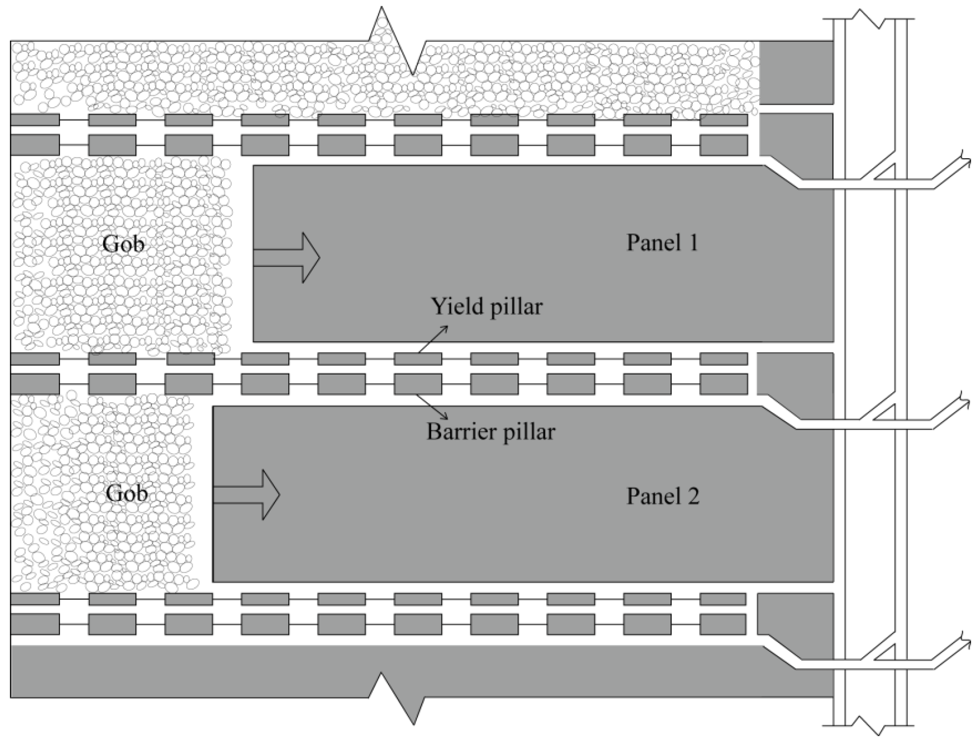
4.1. Optimization on Mining Sequence in Longwall Mining Along Strike
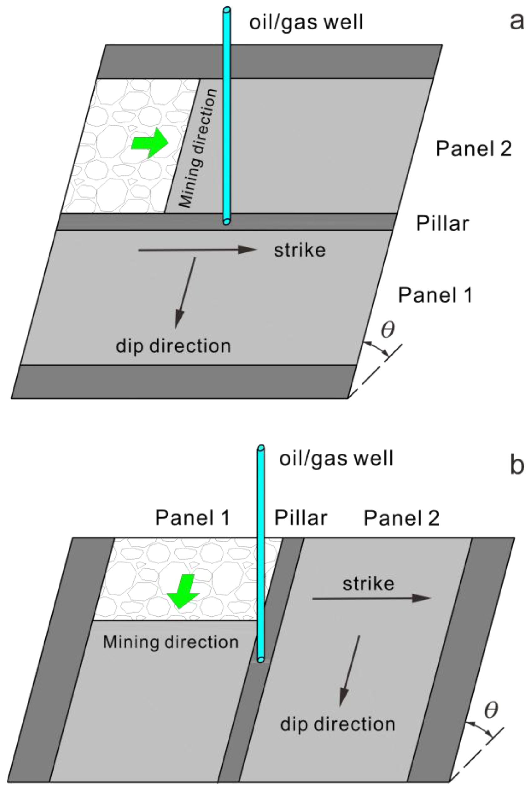
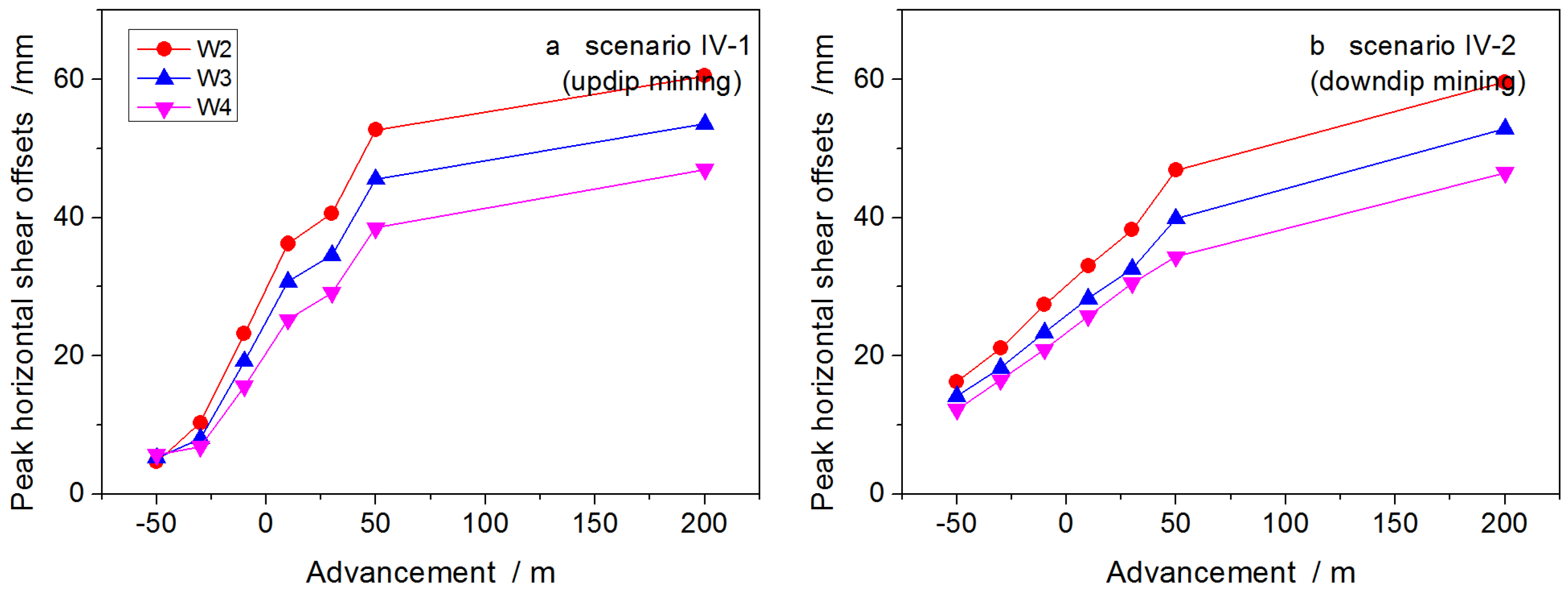
4.2. Optimization of Panel Advance Direction in Longwall Mining Along Dip
4.3. Recommendations for the Effective Control of Hydrocarbon Well Stability
- Spatiotemporal considerations should be given to maintaining well stability. First, mining openings around the wells should be as symmetrical as possible so as to reduce shear and distortion deformation of the wells. Second, if permissible, installation of wells should be delayed. It is better to install wells after mining-induced strata movement stabilizes. For wells installed before mining, coordinated mining of panels surrounding the wells should be performed. A reasonable mining sequence should be designed so as to create symmetrical mining openings. If permissible, simultaneous extraction of the twin panels or synchronous extraction of the twin panels with a small lag distance (Figure 18) is desired to neutralize the deformation induced by the sequential removal of the panels. It should be noted that the twin panels both have a standalone haulage and ventilation system. For inclined coal seams, if longwall mining along strike is employed, the downdip panel should be extracted before the updip panel; if longwall mining along dip is employed (dip angle ≤12°), either updip or downdip mining can be practiced.
- When the panel approaches the well (e.g., within tens of meters), measures such as reducing the mining height and adjusting panel advance rate, will mitigate well deformation. In cases of shallow but thick coal seams, coupled with low strength overlying strata, panels should be advanced slowly so as to mitigate strata movement and stabilize well deformation. For deep coal seams with high strength overlying strata of significant thickness, where strata failure requires more energy and movement or deformation cannot be effectively propagated, panels should be rapidly advanced so as to shorten the duration of roof deformation and shift the disruptive mining-induced influence away from the well.
- Underground longwall mining provides easy access to modify rocks surrounding the hydrocarbon wells and provides the possibility to carry out such measures as wellbore reinforcement and wall rock de-stressing. Prior to panel extraction, grouting reinforcement through the gateroad (entry) can be performed for wall rocks (the pillar that the well penetrates in the six- or nine-pillar configuration, and its roof and floor rocks) around the hydrocarbon wells as wells in these rocks (pillar) are more vulnerable to failure. The reason for employing grouting reinforcement to the pillar is that the plastic zone within the long-weathered pillar (deformation, corrosion and creep) after panel extraction is very likely to expand significantly as the service life of hydrocarbon wells generally outlives that of the pillar. Grouting can not only plug the fissures within the rock mass, but also strengthen the capacity of the rock to withstand deformation through increasing the cohesion and internal friction angle. Moreover, grouting can improve the mechanical properties of the seam floor and roof interfaces as well as the interfaces between soft and stiff layers, strengthening the cohesive effect at interfaces and restraining shear offsets between beds. In addition, the underlying reason behind the large deformation of the pillar and the adjacent roof and floor rocks is that stresses are highly concentrated when the panel approaches the well. Therefore, borehole pressure relief can be carried out in the stress concentration zones so as to ameliorate the stress condition of the surrounding rocks and reduce deformation of the wells.
- At the base of the main hydrocarbon well, multi-branched horizontal wells are installed, covering an extensive area and serving over a long duration. Therefore, installation of these wells is not only time-consuming, but expensive. For hydrocarbon wells installed in areas where geological conditions are unfavorable and the risk of mining-induced well instability is high, mining methods such as partial extraction, strip extraction, room-and-pillar mining or cut-and-fill mining are recommended.
- For wells to be installed in areas with large existing goafs, exploration wells can be drilled to gain a clear understanding of the condition of the goafs before drilling the hydrocarbon wells. If desired or needed, the goafs may be grouted to improve stability and longevity.
5. Conclusions
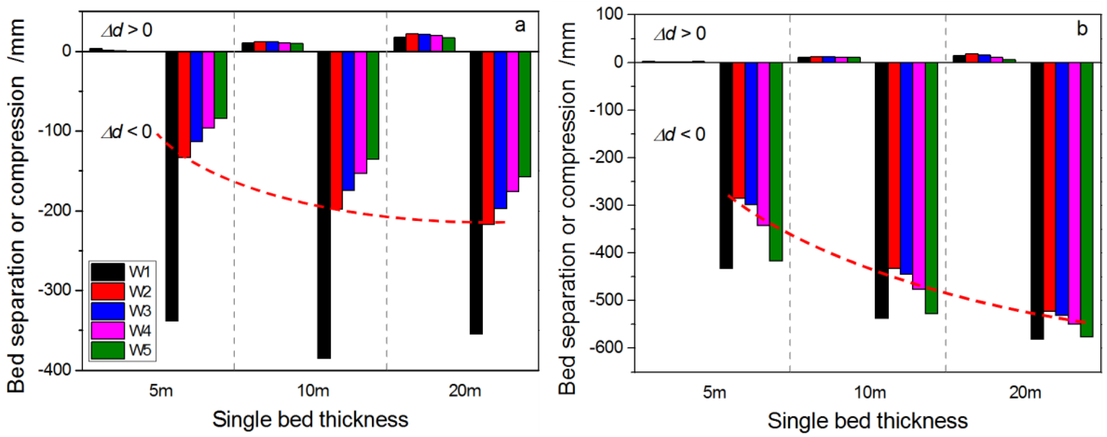
- The peak horizontal shear offset at the weak interface between soft and stiff layers is positively correlated to SRLT. After removal of the first panel, the peak horizontal shear offsets of various wells grow approximately linearly with increasing SRLT; when SRLT doubles, peak horizontal shear offsets grow only by ~40–70%. After removal of the twin panels, peak horizontal shear offsets of wells rise logarithmically with increasing SRLT. Once the SRLT exceeds 10 m, the effect of SRLT on shear deformation at the bedding interfaces apparently attenuates. When SRLT increases from 5 to 10 m, peak horizontal shear offsets of wells grow by ~20–50%. After either one or both panels are removed, vertical delamination and compression of wells rise approximately logarithmically with increasing SRLT.
- The peak horizontal shear offsets of wells at interfaces are positively correlated to SMH. As well trajectory W1 is closest to the first mined panel, it suffers the most severe mining-induced influence. The peak horizontal shear offset of well trajectory W1 grows linearly with increasing SMH after the first panel is removed. Conversely, peak horizontal shear offsets of the other well trajectories (W2–W5) rise approximately logarithmically with increasing SMH after either one or both panels are removed. The difference between effects of increasing SMH on the magnitude of shear offsets of various wells is magnified after the extraction of the second panel. As SMH increases, vertical delamination and compression between beds both grow approximately logarithmically after either one or both panels are removed. Moreover, the difference between the effects of increasing SMH on the magnitude of vertical compressions of various wells is smaller after both panels are removed.
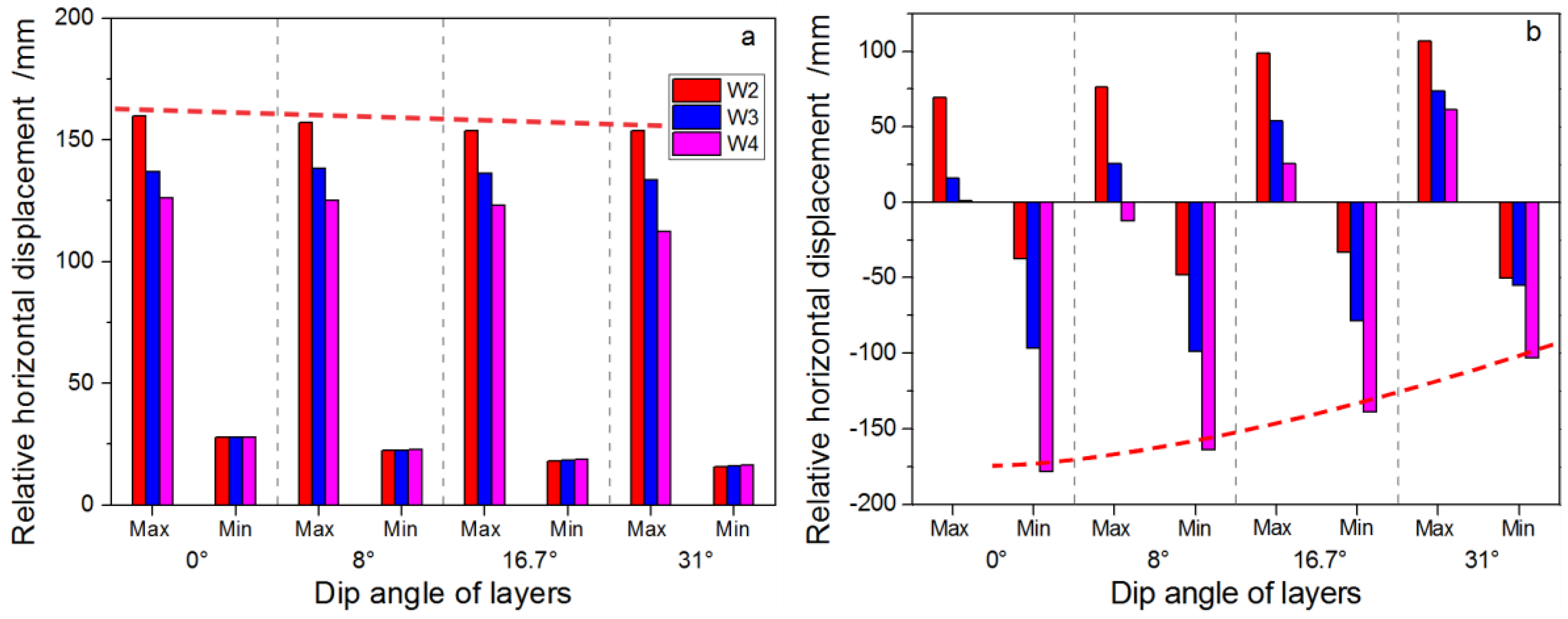
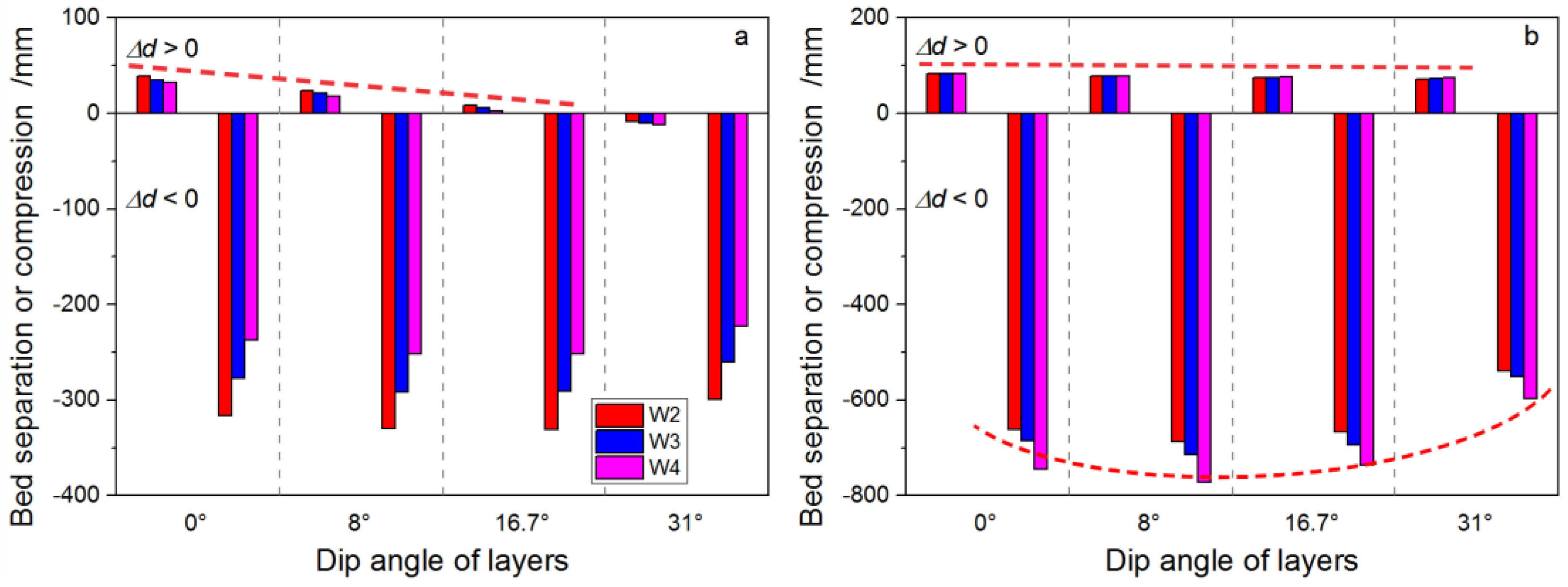
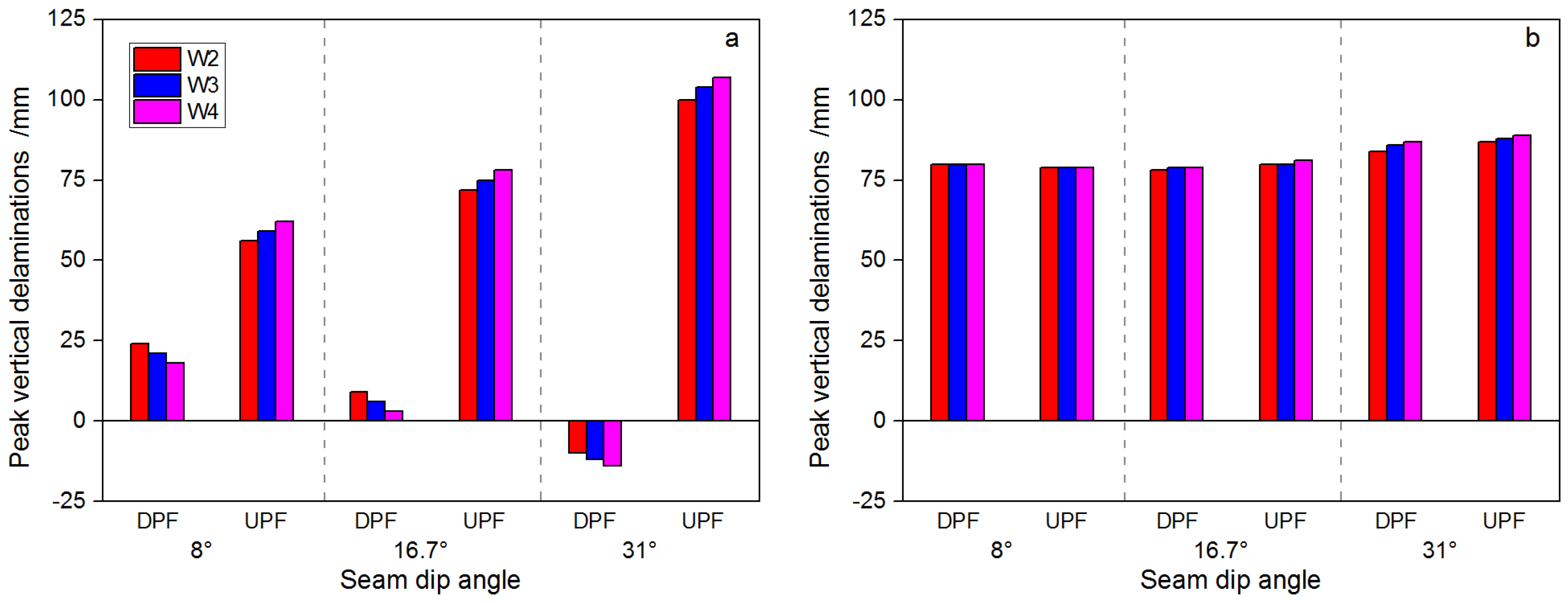
- SDA exerts an influence on deformation at bedding interfaces. This influence is compounded by the layout of panels inside the inclined coal seam as well as the extraction sequence and the location of the well piercing the pillar. As SDA increases, tensile-induced normal delamination between layers gradually shifts to compression, with shear slip along the inclined interface and compression between beds as the dominant deformation mode. Risk of well shearing due to horizontal shear offset does not increase after either one or both panels are removed. However, shear-tensile/compression at interfaces between beds is elevated, making the well more prone to S-shaped shear failure.
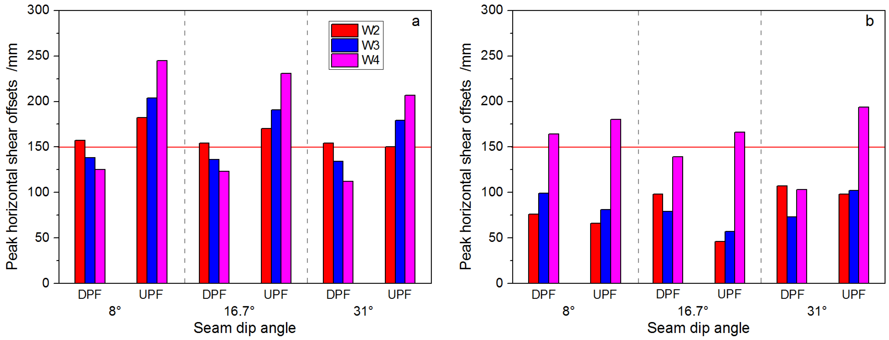
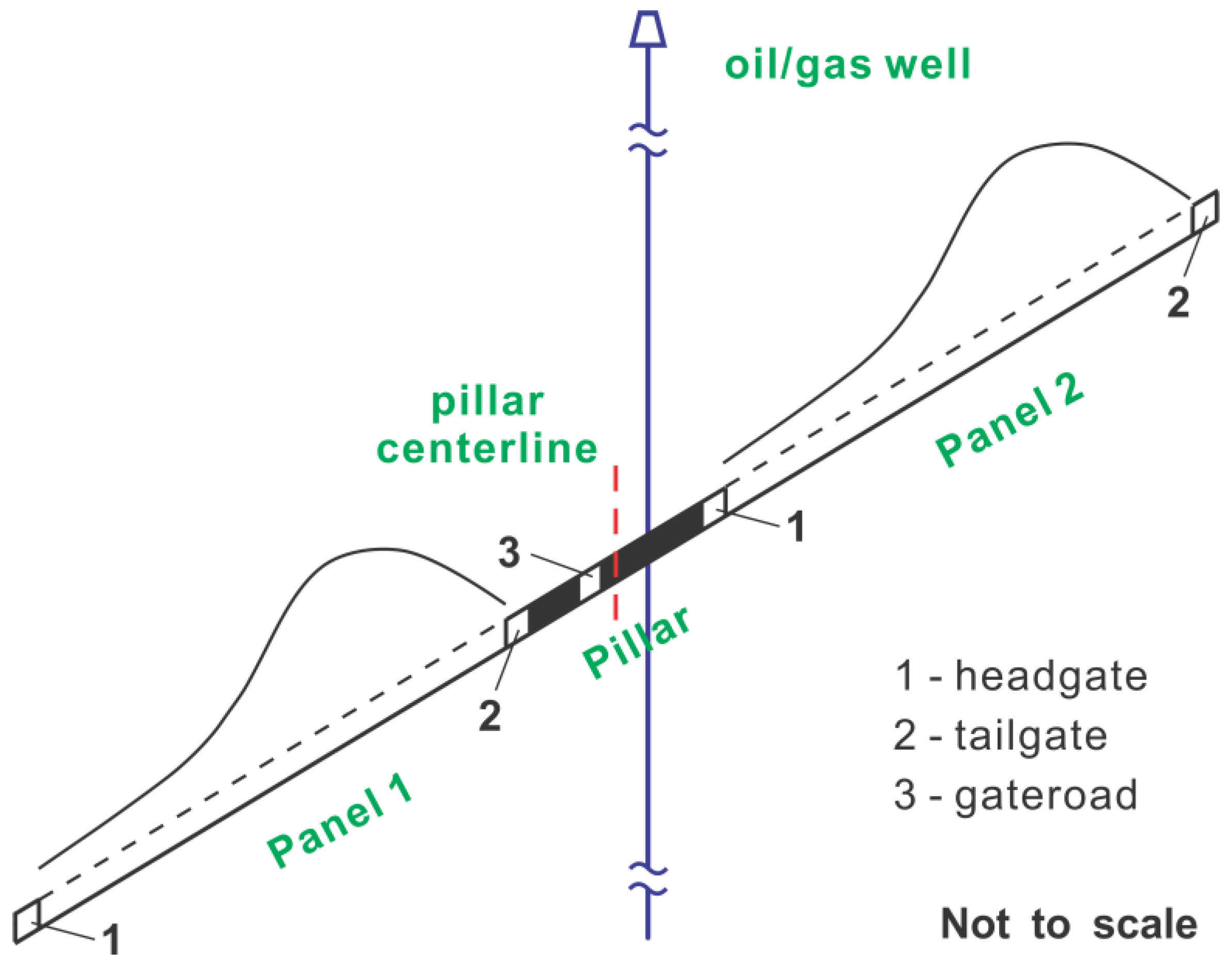
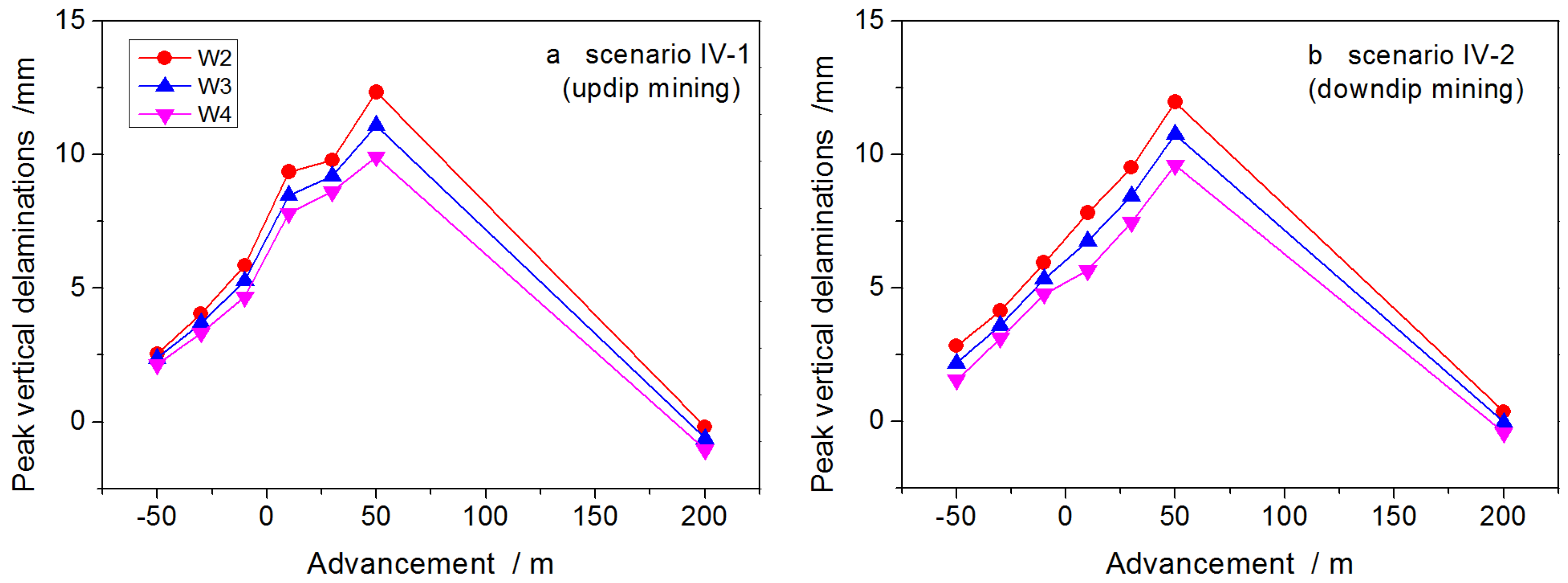
- For longwall panels mined along strike, extraction of the downdip (deep) panel prior to the updip (shallow) side is more favorable for well stability as the horizontal shear offset and vertical delamination between beds are smaller during the whole mining cycle of the twin panels. The offset location of the optimal well trajectory inside the pillar is also correlated to SDA. In general, increasing SDA results in larger deviation of the optimal well trajectory from the pillar centerline, being located closer to the updip panel that is later removed. For longwall mining along dip when SDA is <12°, both the magnitude and evolution of the peak horizontal shear offset and the peak vertical delamination at weak interfaces resulting from both downdip mining and updip mining are similar as the panel advances, indicating that either method is acceptable.
Acknowledgments
Author Contributions
Conflicts of Interest
References
- Feng, X.; Zhang, N.; Chen, X.; Gong, L.; Lv, C.; Guo, Y. Exploitation contradictions concerning multi-energy resources among coal, gas, oil, and uranium: A case study in the Ordos Basin (Western North China Craton and Southern Side of Yinshan Mountains). Energies 2016, 9, 119. [Google Scholar] [CrossRef]
- Christopher, D.L.; Jaime, K.; David, P.G.; Arnold, G.D.; John, A.H. Trenton and Black River carbonates in the Union Furnace area of Blair and Huntingdon Counties, Pennsylvania: Introduction. In Field Trip Guidebook for the Eastern Section AAPG Annual Meeting; John, A.H., Ed.; Pennsylvania Geological Survey: Pittsburgh, PA, USA, 2003. [Google Scholar]
- Liang, S.; Elsworth, D.; Li, X.; Yang, D. Topographic influence on stability for gas wells penetrating longwall mining areas. Int. J. Coal Geol. 2014, 132, 23–36. [Google Scholar] [CrossRef]
- Liang, S.; Elsworth, D.; Li, X.; Fu, X.; Yang, D.; Yao, Q.; Wang, Y. Dynamic impacts on the survivability of shale gas wells piercing longwall panels. J. Nat. Gas Sci. Eng. 2015, 26, 1130–1147. [Google Scholar] [CrossRef]
- Rostami, J.; Elsworth, D.; Watson, R. Study of Borehole Stability for Gas Wells in Longwall Mining Areas; Pennsylvania State University, State College: Hershey, PA, USA, 2012. [Google Scholar]
- Scovazzo, V.A.; Russell, P.M. Industry research into gas and oil well protective coal pillar design. In Proceedings of the 32nd International Conference on Ground Control in Mining, Morgantown, WV, USA, 30 July–1 August 2013; pp. 45–52. [Google Scholar]
- Su, W.H. Effects of longwall-induced stress and deformation on the stability and mechanical integrity of shale gas wells drilled through a longwall abutment pillar. Int. J. Min. Sci. Technol. 2017, 27, 115–120. [Google Scholar] [CrossRef]
- Wang, Y.; Watson, R.; Rostami, J.; Wang, J.; Limbruner, M.; He, Z. Study of borehole stability of Marcellus shale wells in longwall mining areas. J. Petrol. Explor. Prod. Technol. 2013, 4, 1–13. [Google Scholar] [CrossRef]
- Davies, R.J.; Almond, S.; Ward, R.S.; Jackson, R.B.; Adams, C.; Worrall, F.; Herringshaw, L.G.; Gluyas, J.G.; Whitehead, M.A. Oil and gas wells and their integrity: Implications for shale and unconventional resource exploitation. Mar. Pet. Geol. 2014, 56, 239–254. [Google Scholar] [CrossRef]
- Vidic, R.D.; Brantley, S.L.; Vandenbossche, J.M.; Yoxtheimer, D.; Abad, J.D. Impact of shale gas development on regional water quality. Science 2013, 340, 1235009. [Google Scholar] [CrossRef] [PubMed]
- Miyazaki, B. Well integrity: An overlooked source of risk and liability for underground natural gas storage. Geol. Soc. 2009, 313, 163–172. [Google Scholar] [CrossRef]
- Rice, G.S.; Hood, O.P. Oil and Gas Wells through Workable Coal Beds: Papers and Discussions; Bureau of Mines: Washington, DC, USA, 1913.
- Peng, S.; Morsey, K.; Zhang, Y.; Luo, Y.; Heasley, K. Technique for assessing the effects of longwall mining on gas wells—Two case studies. Trans. Soc. Min. metal. Explor. Inc. 2003, 314, 107–115. [Google Scholar]
- Liang, S. Study on the Stability of Vertical Shale Gas Wells Penetrating Longwall Mining Areas. Ph.D. Thesis, China University of Mining and Technology, Xuzhou, China, 2015. [Google Scholar]
- Karacan, C.Ö.; Goodman, G. Hydraulic conductivity changes and influencing factors in longwall overburden determined by slug tests in gob gas ventholes. Int. J. Rock Mech. Min. Sci. 2009, 46, 1162–1174. [Google Scholar] [CrossRef]
- Palchik, V. Localization of mining-induced horizontal fractures along rock layer interfaces in overburden: Field measurements and prediction. Env. Geol. 2005, 48, 68–80. [Google Scholar] [CrossRef]
- Palchik, V. Experimental investigation of apertures of mining-induced horizontal fractures. Int. J. Rock Mech. Min. Sci. 2010, 47, 502–508. [Google Scholar] [CrossRef]
- Qian, M. Theoretical study of key stratum in ground control. J. China Coal Soc. 1996, 21, 225–230. [Google Scholar]
- Aadnoy, B.S.; Chenevert, M.E. Stability of highly inclined boreholes. SPE Drill. Eng. 1987, 2, 364–374. [Google Scholar] [CrossRef]
- Gough, D.I.; Bell, J.S. Stress orientations from oil-well fractures in Alberta and Texas. Can. J. Earth Sci. 1981, 18, 638–645. [Google Scholar] [CrossRef]
- Haimson, B.C.; Song, I. Laboratory study of borehole breakouts in Cordova Cream: A case of shear failure mechanism. Int. J. Rock Mech. Min. 1993, 30, 1047–1056. [Google Scholar] [CrossRef]
- Tan, C.P.; Rahman, S.S.; Richards, B.G.; Mody, F.K. Integrated rock mechanics and drilling fluid design approach to manage shale instability. In Proceedings of the SPE/ISRM Rock Mechanics in Petroleum Engineering, Trondheim, Norway, 8–10 July 1998. [Google Scholar]
- Tan, C.P.; Willoughby, D.R. Critical mud weight and risk contour plots for designing inclined wells. In Proceedings of the 68th Annual Technical Conference and Exhibition of the Society of Petroleum Engineers, Houston, TX, USA, 3–6 October 1993; pp. 101–115. [Google Scholar]
- Zheng, Z.; Kemeny, J.; Cook, N.G.W. Analysis of borehole breakouts. J. Geophys. Res. 1989, 94, 7171. [Google Scholar] [CrossRef]
- Zoback, M.D.; Moos, D.; Mastin, L.; Anderson, R.N. Well bore breakouts and in situ stress. J. Geophys. Res. Solid Earth 1985, 90, 5523–5530. [Google Scholar] [CrossRef]
- Bennion, D.B.; Thomas, F.B.; Bietz, R.F. Low permeability gas reservoirs: problems, opportunities and solutions for drilling, completion, stimulation and production. In Proceedings of the SPE Gas Technology Symposium Society of Petroleum Engineers, Calgary, AB, Canada, 28 April–1 May 1996; pp. 117–131. [Google Scholar]
- Bjornsson, E.; Hucik, B.; Szutiak, G.; Brown, L.A.; Evans, H.; Curry, D.; Perry, P. Drilling optimization using bit selection expert system and ROP prediction algorithm improves drilling performance and enhances operational decision making by reducing performance uncertainties. In Proceedings of the SPE Annual Technical Conference and Exhibition, Society of Petroleum Engineers, Houston, TX, USA, 26–29 September 2004; pp. 1–6. [Google Scholar]
- Clancey, B.; Khemakhem, A.S.; Bene, T.; Schmidt, M. Design, construction and optimization of big-bore gas wells in a giant offshore field. In Proceedings of the SPE/IADC Drilling Conference, Amsterdam, The Netherlands, 20–22 February 2007; pp. 1–9. [Google Scholar]
- Supon, S.B.; Adewumi, M.A. Experimental study of the annulus pressure drop in a simulated air-drilling operation. SPE Drill. Eng. 1991, 6, 74–80. [Google Scholar] [CrossRef]
- Bruno, M.S. Subsidence-induced well failure. SPE Drill. Eng. 1992, 7, 148–152. [Google Scholar] [CrossRef]
- Chen, J.; Wang, T.; Zhou, Y.; Zhu, Y.; Wang, X. Failure modes of the surface venthole casing during longwall coal extraction: A case study. Int. J. Coal Geol. 2012, 90–91, 135–148. [Google Scholar] [CrossRef]
- Dusseault, M.B.; Bruno, M.S.; Barrera, J. Casing shear: Causes, cases, cures. SPE Drill. Complet. 2001, 16, 98–107. [Google Scholar] [CrossRef]
- Liu, C.; Zhou, F.; Yang, K.; Xiao, X.; Liu, Y. Failure analysis of borehole liners in soft coal seam for gas drainage. Eng. Fail. Anal. 2014, 42, 274–283. [Google Scholar] [CrossRef]
- Whittles, D.N.; Lowndes, I.S.; Kingman, S.W.; Yates, C.; Jobling, S. The stability of methane capture boreholes around a long wall coal panel. Int. J. Coal Geol. 2007, 71, 313–328. [Google Scholar] [CrossRef]
- Gutierrez, J.J. Estimating Highway Subsidence Due to Longwall Mining. Master’s Thesis, University of Pittsburgh, Pittsburgh, PA, USA, 2008. [Google Scholar]
- Jeran, P.; Adamek, V. Subsidence Due to Undermining of Sloping Terrain: A Case Study; United States Department of Interior Bureau of Mines: Washington, DC, USA, 1988.


| Study Group | Scenario | SRLT (m) | SMH (m) | SDA (°) | Seam Burial Depth (m) |
|---|---|---|---|---|---|
| Group I | I-1 | 5 | 2 | 0 | 300 |
| I-2 | 10 | 300 | |||
| I-3 | 20 | 300 | |||
| Group II | II-1 | 10 | 1 | 0 | 300 |
| II-2 (I-2) | 2 | 300 | |||
| II-3 | 3 | 300 | |||
| II-4 | 4 | 300 | |||
| Group III | III-1 | 10 | 2 | 0 | 900 |
| III-2 | 8 | 900 | |||
| III-3 | 16.7 | 900 | |||
| III-4 | 31 | 900 |
| Lithology | Thickness (m) | Cumulative Thickness (m) | Bulk K (GPa) | Shear G (GPa) | Density ρ (Kg/m3) | Cohesion c (MPa) | Friction Angle Φ (°) | Tension σt (MPa) | ||
|---|---|---|---|---|---|---|---|---|---|---|
| - | 280 | 300 | Alternating layers of soft shale and stiff sandstone in overburden | |||||||
| Sandstone/limestone | 10 | 302 | 13.3 | 8.0 | 2650 | 88 | 30 | 1.0 | ||
| Shale/mudstone | 10 | 3.3 | 2.0 | 2300 | 21 | 30 | 0.4 | |||
| Coal seam | 2.0 | 2.3 | 1.4 | 1500 | 1.5 | 30 | 0.01 | |||
| Shale/mudstone | 10 | 3.3 | 2.0 | 2300 | 21 | 30 | 0.4 | |||
| Sandstone/limestone | 10 | 13.3 | 8.0 | 2650 | 88 | 30 | 1.0 | |||
| - | 280 | 602 | Alternating layers of soft shale and stiff sandstone in underburden | |||||||
| Mechanic Properties of Interfaces between Adjacent Beds | ||||||||||
| Shear Stiffness Ks (MPa) | Normal Stiffness Kn (MPa) | Friction Angle φ (°) | ||||||||
| 17 | 17 | 20 | ||||||||
© 2017 by the authors. Licensee MDPI, Basel, Switzerland. This article is an open access article distributed under the terms and conditions of the Creative Commons Attribution (CC BY) license (http://creativecommons.org/licenses/by/4.0/).
Share and Cite
Liang, S.; Elsworth, D.; Fu, X.; Li, X.; Yao, Q. Influence of Stratigraphic Conditions on the Deformation Characteristics of Oil/Gas Wells Piercing Longwall Pillars and Mining Optimization. Energies 2017, 10, 775. https://doi.org/10.3390/en10060775
Liang S, Elsworth D, Fu X, Li X, Yao Q. Influence of Stratigraphic Conditions on the Deformation Characteristics of Oil/Gas Wells Piercing Longwall Pillars and Mining Optimization. Energies. 2017; 10(6):775. https://doi.org/10.3390/en10060775
Chicago/Turabian StyleLiang, Shun, Derek Elsworth, Xuehai Fu, Xuehua Li, and Qiangling Yao. 2017. "Influence of Stratigraphic Conditions on the Deformation Characteristics of Oil/Gas Wells Piercing Longwall Pillars and Mining Optimization" Energies 10, no. 6: 775. https://doi.org/10.3390/en10060775