
Effects of Variable Diffuser Vanes on Performance of a Centrifugal Compressor with Pressure Ratio of 8.0


Turbomachinery Laboratory, State Key Laboratory of Automotive Safety and Energy, Tsinghua University, Beijing 100084, China
*
Author to whom correspondence should be addressed.
Energies 2017, 10(5), 682; https://doi.org/10.3390/en10050682
Submission received: 4 April 2017
/
Revised: 6 May 2017
/
Accepted: 9 May 2017
/
Published: 12 May 2017
(This article belongs to the Section I: Energy Fundamentals and Conversion)
Abstract
:In numerous applications, centrifugal compressors are required to provide a high pressure ratio with good efficiency while also working in a wide operating range. This is a challenge because as pressure ratio increases, efficiency and operating range inevitably decline. This paper studies the effects of a variable geometry diffuser on the performance and operating range of a centrifugal compressor with high pressure ratios of up to 8.0. The numerical method employed three-dimensional Reynolds-averaged Navier-Stokes simulations. An analysis of the matching of the vaned diffuser with the impeller for different working conditions and diffuser vane angles is presented. The results show that improved matching of the adjusted diffuser increased efficiency by 4.5%. The range extension mechanism of the variable diffuser is explained, and it is shown that adjusting the vane angle by +6° to −6° extended the operating range of the compressor by up to 30.0% for pressure ratios between 5.0 and 6.0. The interaction between diffuser and impeller was examined, and the independent characteristic of the impeller is illustrated. The connection between the incidence angle at the leading edge of the impeller and flow separation near the tip of the impeller is discussed.
1. Introduction
Centrifugal compressors are extensively used in the industry [1]. Besides gas turbines and turboshaft engines, unmanned air vehicles (UAVs) are also one of the important applications of centrifugal compressors. Compression ignition engines are suggested as a suitable choice for the propulsion system of high altitude unmanned air vehicles [2,3,4]. Because of the lower air consumption compared to turbojets, turbocharged compression ignition engines can deliver constant power at different levels of altitude. However, to maintain constant inlet manifold pressure at high altitudes, a turbocharger with a high-pressure ratio centrifugal compressor is needed. Furthermore, high-altitude aircraft need to have long endurance, which requires using propulsion systems with high efficiency [4]. Designing a highly efficient centrifugal compressor with a high pressure ratio needs to use the vaned diffuser. However, the use of vaned diffusers will narrow the stable operating range of the compressor.
The operation of a high pressure ratio centrifugal compressor with a wide operating range involves the impeller and/or the diffuser working close to or above their stability margin [5]. As a result, flow instability is a bottleneck for developing high pressure ratio centrifugal compressors with wide flow range. At high pressure ratio, the considerable negative pressure gradient in the flow path of the compressor inevitably causes flow instability, which restricts the operating range of a compressor. In addition, the matching between the impeller and diffuser plays a crucial role in designing a high-performance centrifugal compressor. According to Cumpsty [6], poor matching between the impeller and diffuser is a common reason for low performance of the high pressure ratio compressors.
Various methods have been proposed and used for extending the operating range and improving the performance of compressors. Examples of these methods are the application of backswept blades [7], casing treatment [8], tandem diffusers [9], and shell cooling [10]. The variable geometry method is an alternative way to improve the performance and operating range of the compressor by adjusting the geometry of the compressor under different working conditions [11]. Potential locations for the application of the variable geometry method are upstream and downstream of the impeller. The variable vaned diffuser is one of the applications of the variable geometry method. In this approach, the geometrical parameters of the diffuser’s blade, such as blade stagger angle, distance from impeller blade’s trailing edge and blade’s solidity, are adjustable. In each scenario, the geometry would be changed in such a way that the performance of the compressor adapts to the operational requirements. Simon et al. [12] used a vaned diffuser with a different angle in conjunction with variable inlet guide vanes to improve both the operating range and the efficiency of the compressor. Salvage [13] employed a variable geometry split-ring pipe diffuser to improve the surge margin of a compressor with an excess impeller-diffuser gap. Ziegler et al. [14] used a vaned diffuser with adjustable vane angle and radial gap between diffuser vanes and the impeller to study the interaction between the diffuser and the impeller. They adjusted the radial gap ratio between 1.04 and 1.18 and found that the total pressure ratio of the compressor rises with a decrease of radial gap. In a recent work, Huang et al. [15] found that the variable diffuser method can extend the stable operating range of a centrifugal compressor from 23.5% to 54.9% at a pressure ratio of 4.8 with changing the diffuser vane angles by 10°.
In the recent years, with the rising demand for UAVs, turbocharged engines and gas turbines with higher performance, research on high-pressure ratio centrifugal compressors with wide operating ranges is gaining popularity. Zheng et al. [16] showed the potential benefit of the operating range extension of the centrifugal compressor for a turbocharged engine and its operating line. In order to meet requirements of future engine generations, compressors with pressure ratios significantly higher than the current standard are required [17,18]. The application of variable diffuser vanes on the high pressure ratio compressor has not been reported in the literature, and the validity of the effects on the performance of such compressor has not been verified. In this paper, effects of variable diffuser vanes on the performance of a centrifugal compressor with a high pressure ratio of 8.0 are investigated. The compressor is of a new design that is under development for application in gas turbines and the future generation of single-stage high pressure ratio turbochargers.
The main body of this work consists of three parts. Firstly, the research methodology is stated. Secondly, compressors maps with different setups of diffuser vane angles are shown, and the effects of variable diffuser vanes on range extension and performance are discussed. Thirdly, component performances, especially the impeller’s characteristics, are analyzed to reveal flow physics and intention to provide new insights for compressor design.
2. Methodology
In this study, CFD simulations were conducted based on three-dimensional, steady-state, compressible, finite volume layout. Numeca FINE/Turbo 10.1 EURANUS solver was used for the computations to solve Reynolds-averaged Navier-Stokes equations. The central scheme with Jameson type dissipation [19] and fourth-order Runge-Kutta scheme were used for spatial and temporal discretization respectively. The Spalart-Allmaras one-equation model [20] was selected as turbulence model.
We used a high pressure ratio centrifugal compressor. The compressor has 24 impeller blades, 19 diffuser vanes and can achieve peak pressure ratio of 8.0 and peak isentropic efficiency of 79.9%; Other details are presented in Table 1. We meshed passage of impeller and diffuser together and applied periodic matching on the side faces of the passage to make the computational domain. We employed a multi-block structured mesh with O4H topology scheme. The final grid of a single passage consisted of 1 million nodes which 56% of them were allocated to the impeller. The tip clearance was set to constant 5.6% of exit blade height. The minimum skewness angles in the impeller and diffuser were 16° and 37° respectively, and maximum expansion ratios were below 3. The average y+ of the mesh was around 1.6 with the highest value lower than 10, which is suitable for the Spalart-Allmaras turbulence model to appropriately resolve the viscous sublayer. A schematic of the impeller blade and diffuser vane passages is shown in Figure 1.
Boundary conditions at the inlet consisted of the absolute total temperature of 288.15 K, the absolute total pressure of 101.325 kPa and the normal velocity. Likewise, an averaged static pressure with backflow control was imposed at the outlet. The casing surface and blades were defined as static non-slip solid boundary and rotational non-slip solid boundary, respectively. The non-reflecting 2D method was used to model the rotor-stator interface. The same compressor prototype with the same numerical setup was used in a previous study by present co-authors, and the mesh quality, grid independency, and reliability of the turbulence model were validated [21]. The simulations were performed at 1.0Nmax, 0.9Nmax, 0.8Nmax and 0.6Nmax rotational speeds. The peak of each pressure ratio speed line was determined to be the surge point as it provides a good approximation for the flow instability [6]. Diffuser vanes were rotated in the range of [–6°, 6°] to investigate the effects of diffuser vane angles on the performance of the compressor. The leading edge of the diffuser vanes was used as a pivot point for the rotation, to maintain the width of the vaneless region and the gap ratio between impeller blade’s trailing edge and diffuser vane’s leading edge. A schematic of the impeller and diffuser vanes with different stagger angles is shown in Figure 2. The angles are relative to the stagger angle of the datum diffuser. For the closed diffuser, the diffuser vanes were rotated clockwise, and the diffuser throat area decreased, while for the open diffuser, the vanes were rotated counter-clockwise and the diffuser throat area increased.
3. Results and Discussion
3.1. Discussion on Extension of Stable Operating Range
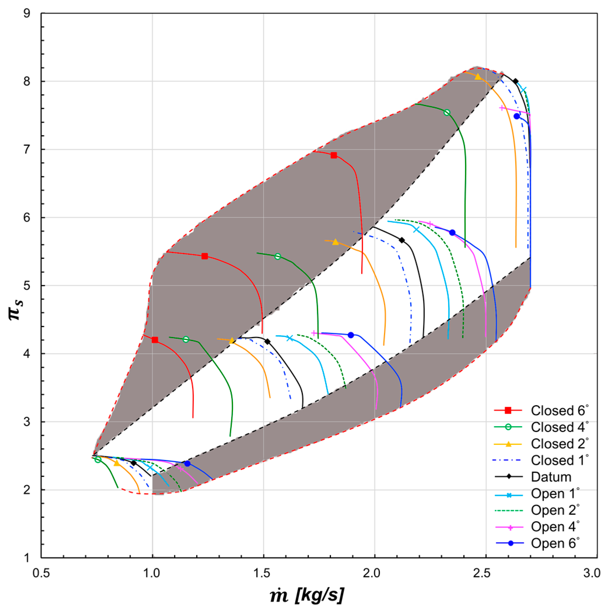
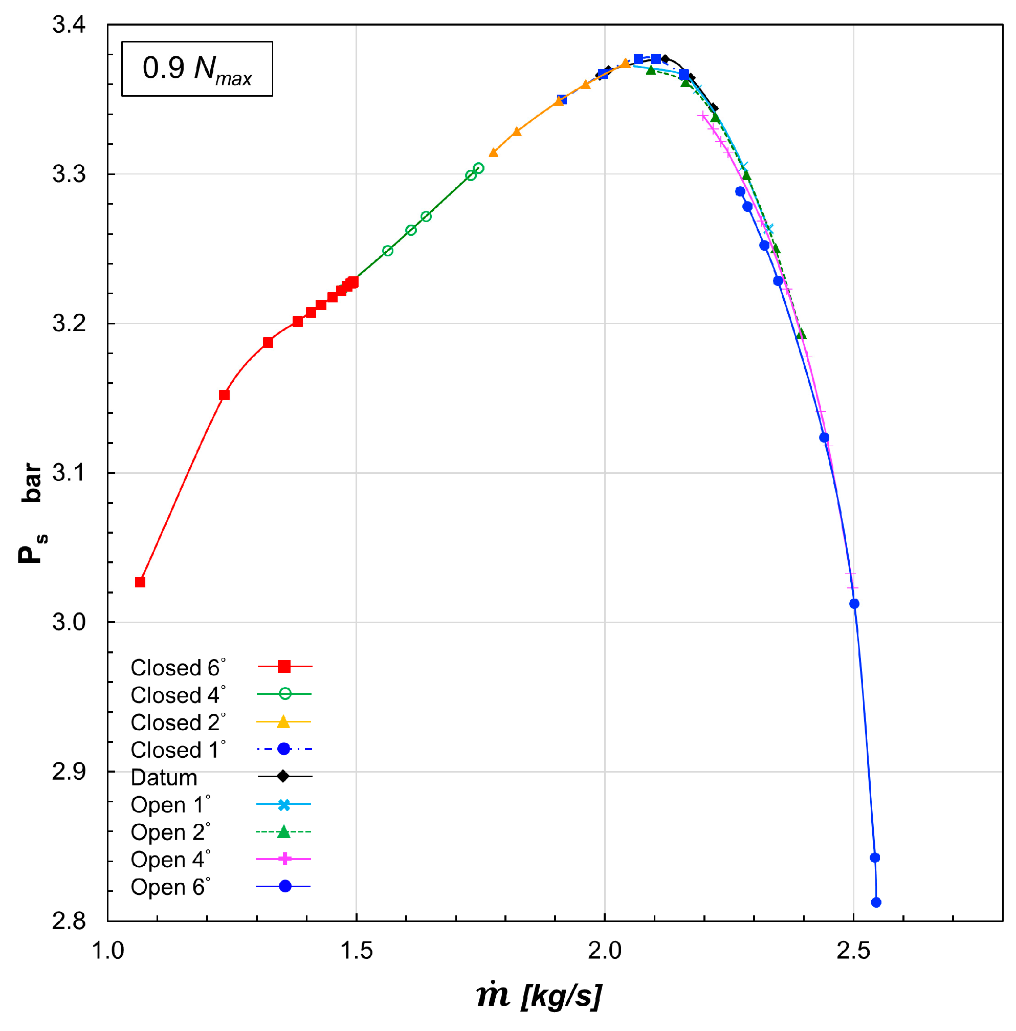
The compressor pressure ratio characteristic curves for various stagger angles of diffuser vanes are shown in Figure 3.
The datum compressor reaches a pressure ratio of 8.0 at the maximum rotational speed. The extended part of the operating range is highlighted and can be compared with the operating range of the datum compressor. It can be seen that the compressor with variable diffuser vanes has a significantly wider range compared to the datum compressor. In order to evaluate the range extension potential of the variable diffuser, the stable operating range (SOR) of compressor is defined by Equation (1). In Equation (1), and represent the lowest and highest mass flow rates within the operating range at each pressure ratio, respectively.
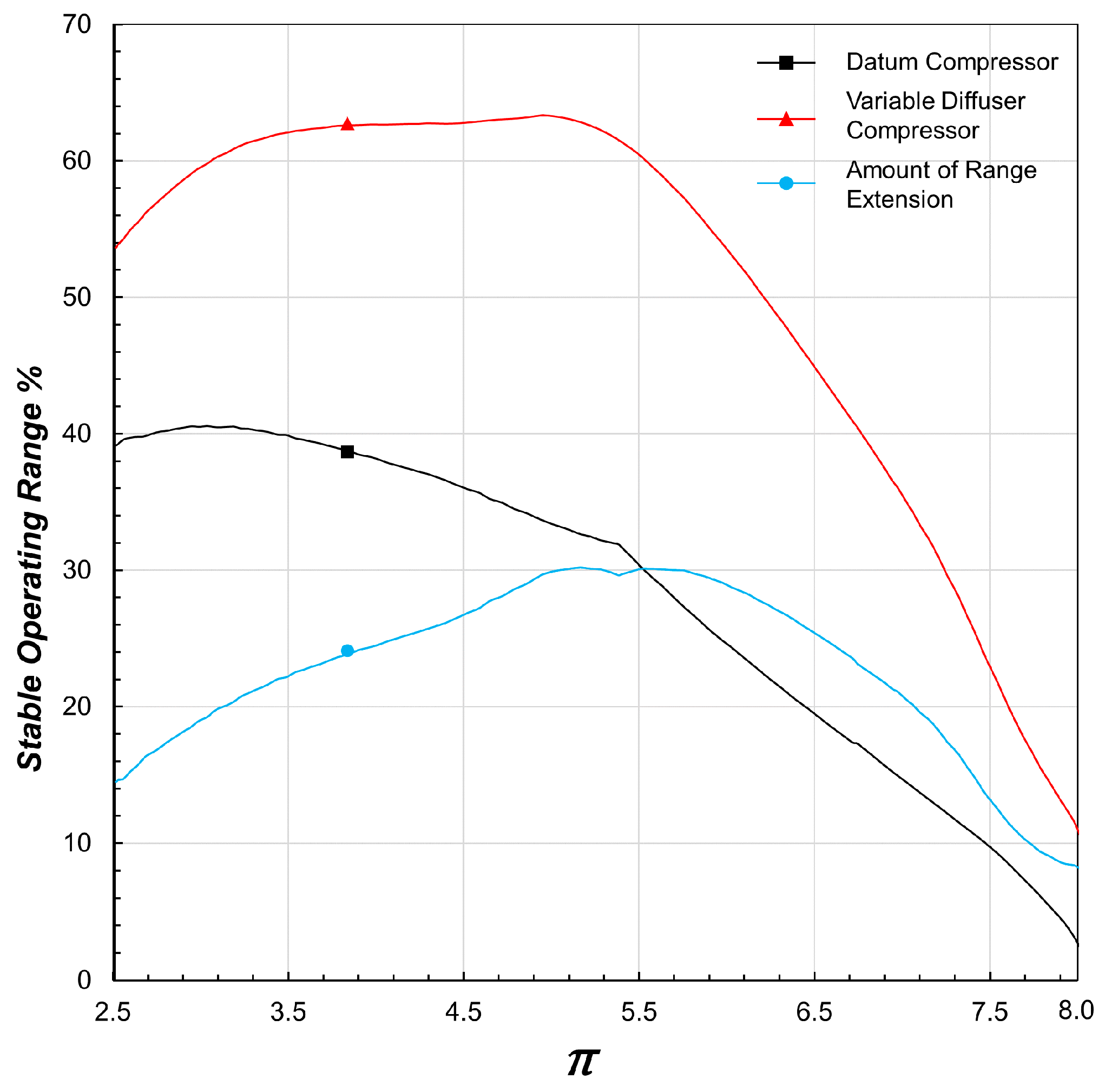
The stable operating ranges of the datum compressor and the compressor with variable diffuser vane angles are shown in Figure 4. The difference between the two is the extended range value that is achieved by employing the variable geometry method. The highest stable operating range of the datum compressor is 40.5%, which is at a low pressure ratio of 3.0. By using a variable angle vaned diffuser, operating range increases greatly and reaches the maximum of 63.3% at the medium pressure ratio of 4.9.
Because of the various effects of the variable diffuser on the compressor performance and the mechanisms governing the range extension at different speeds and pressure ratios, the amount of range extension of the compressor is not constant and varies with different rotation speeds and pressure ratio levels. When we close the diffuser, the operating range of the compressor shifts to the left on the map because of the decrease of the surge mass flow rate. On the other hand, when we open the diffuser, the choke mass flow rate increase and the operating range shifts to the right on the map. At maximum pressure ratio and rotational speed (Nmax), the shift of the surge line to the lower mass flow rates because of the closing of the diffuser is the main factor for the operating range extension. Although at this rotation speed the opening of the diffuser increases the throat area of the diffuser, it does not have any effects on the choke mass flow rate of the compressor. This indicates that at Nmax choking does not happen at the diffuser, and choke mass flow rate of the compressor is dominantly controlled by the choking in the impeller. Since at high pressure ratios of above 7.0 the range extension is only due to the shift of the surge line, the amount of range extension is below 20%.
At medium pressure ratio (4 to 6) and rotational speed (0.9Nmax, 0.8Nmax), closing the diffuser shifts the surge line significantly to the left on the map and widen the stable operating range. Besides, opening the diffuser moves the choke line to the right, toward the higher mass flow rates. At these rotational speeds, the choking of the datum compressor no longer happens at the impeller and the choke mass flow rate of the compressor is determined by the diffuser. Because the choking of the diffuser happens at the throat of the diffuser, the higher throat area of the open diffuser increases the choke mass flow of the diffuser, which in turn increases the choke mass flow rate of the compressor. Since at medium pressure ratios both surge and choke lines shift by changing the angles of the diffuser vanes, the amount of range extension increases and reaches the peak of 30% for pressure ratios between 5.0 and 6.0.
At a low pressure ratio and rotational speed (0.6Nmax), opening the diffuser increases the choke mass flow rate of the compressor and expands the operating range of the compressor by shifting the choke line. However, the surge mass flow rate of the compressor has very little change. At low mass flow rates, the tip region of the leading edge of the impeller is highly unstable. This is the main reason for instability and stall in the compressor at low rotation speeds and pressure ratios. Because of this, closing the diffuser vanes does not improve the stability of the compressor, and the surge mass flow rate of the compressor does not change. Therefore, the amount of range extension of the datum compressor decreases to about 15% at a low pressure ratio of 2.5.
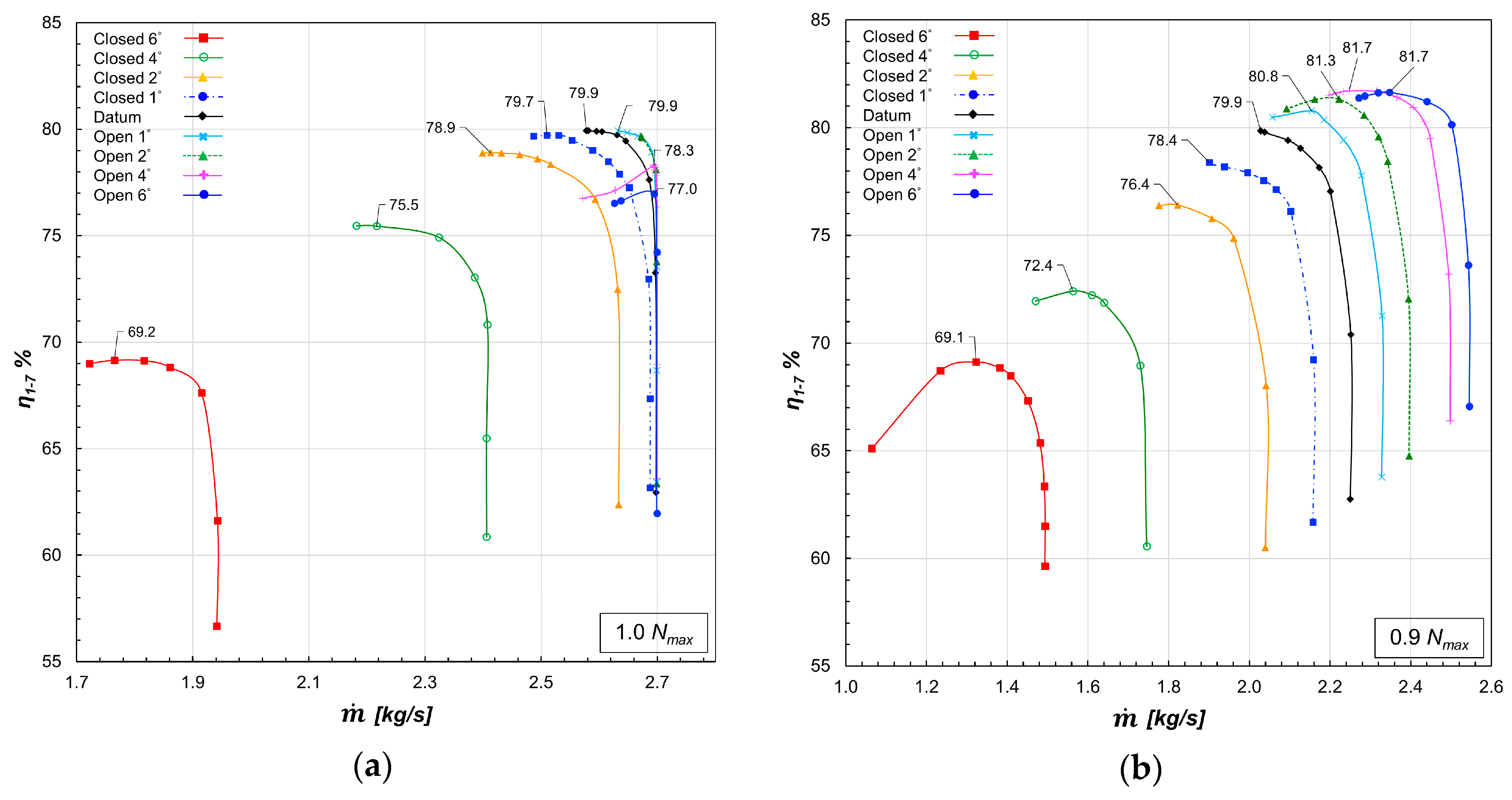
3.2. Discussion on Efficiency Performance
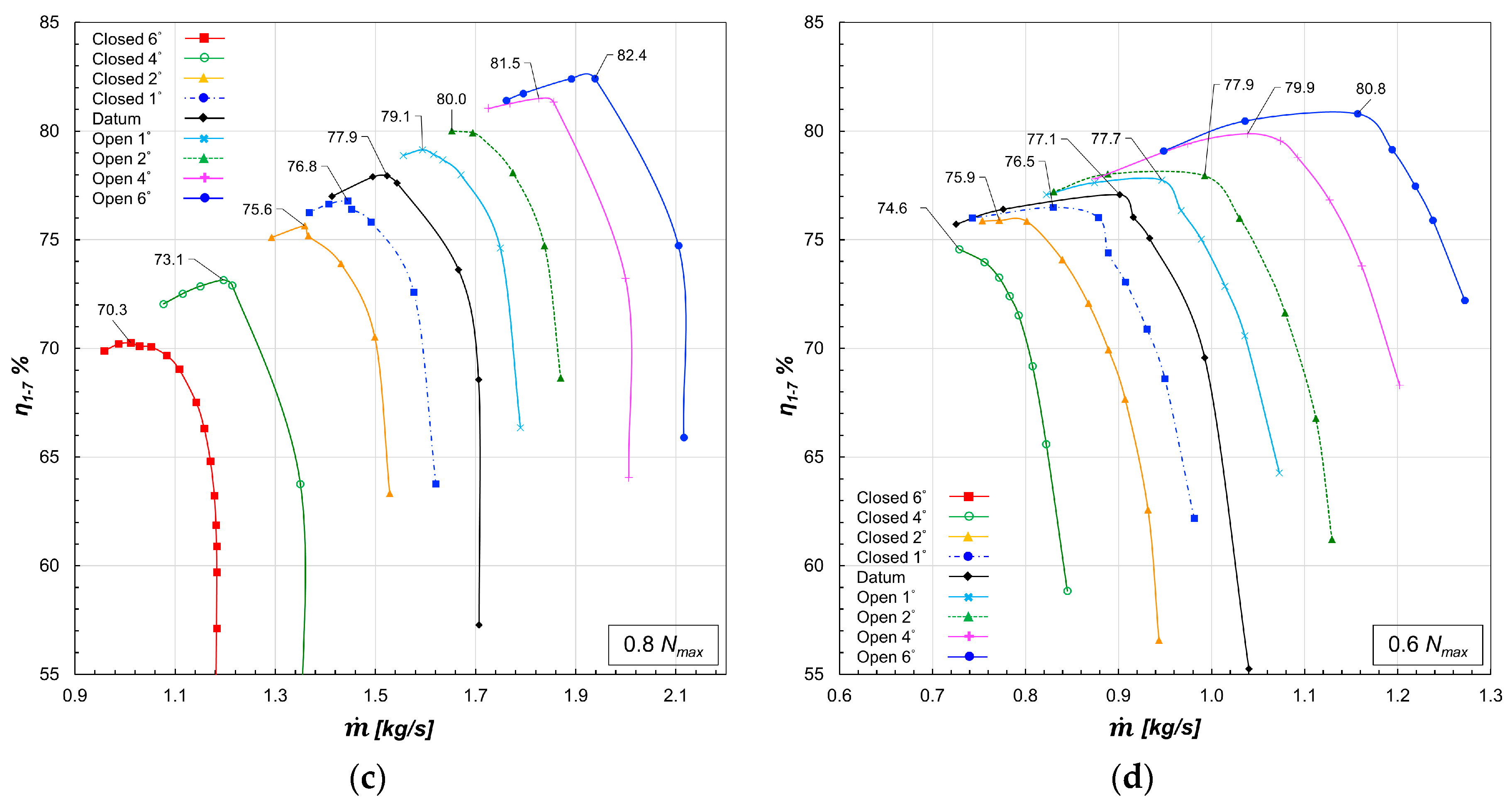
The compressor efficiency for different diffuser vane angles and rotational speeds are shown in Figure 5. As shown in Figure 5a, at high rotational speed and pressure ratio despite significant range extension, the efficiency of the compressor decreases by closing the diffuser vanes. At maximum rotational speed (Nmax), the datum compressor reaches the peak efficiency of 79.9%, while the “closed 6°” case reaches a peak efficiency of only 69.1%. We can see the same trend at the rotational speed of 0.9Nmax for closing the diffuser. By contrast, at this speed, the efficiency of the diffuser increases by opening the diffuser vanes and the “open 4°” case has the highest efficiency of 81.7%. This is because the impeller and diffuser of the datum compressor were designed and matched for the best efficiency at the Nmax as it is the design speed. However, as the rotational speed of the compressor decreases, the impeller and diffuser become unmatched since the diffuser throat area needed for the appropriate matching increases [22]. As a result, at lower rotational speeds of 0.8Nmax and 0.6Nmax the compressor with the largest diffuser throat area, which is the “open 6°” case, has the highest efficiency.
For further discussion of the efficiency performance of the compressor at different speeds for different diffuser vane angles, it is necessary to evaluate the matching between the impeller and diffuser. As shown by Tamaki et al. [23], if the flow capacity of the impeller and that of the diffuser match closely; the compressor will have the best performance at the design speed. This assumption also applies to the speeds higher or lower than the design speed. As demonstrated by Dixon and Hall [24], the choke mass flows of the impeller and vaned diffuser are dependent on the impeller blade speed and stagnation conditions at the diffuser inlet, respectively, besides their respective throat area. These circumstances vary at different rotational speeds so the component that chokes and determines the choke mass flow rate of the compressor for each speed line may be different. To analyze the choke mass flow of the impeller and diffuser and the matching between them, we study the component performance of the impeller and diffuser.
The diffuser loss coefficient and adiabatic efficiency of the impeller for different cases are shown in Figure 6. The impeller efficiency calculated by using the gas-state parameters of the inlet, the rotor-stator interface and the outlet of the compressor and Equation (2).
The diffuser loss coefficient is computed by using Equation (3).
As stated before, at maximum rotational speed, the datum compressor has the highest efficiency. The reason is that as we see in Figure 6a, the choke mass flow rate of the impeller (2.69 kg/s) is in line with the choke mass flow rate of the diffuser. The close matching of the choke mass flow rates makes the impeller and diffuser work at their highest performance at a mass flow rate of 2.57 kg/s, which is the peak efficiency point of the stage. In other diffuser vane configurations, due to the alteration of the diffuser throat area, the choke mass flow rate of the diffuser changes and mismatches with the impeller. This mismatching results in the significant drop in the stage efficiency, and as this mismatching increases by closing the diffuser vanes, the stage efficiency decreases further.
The choke mass flow rates of both impeller and diffuser decrease as the rotational speed of the impeller decreases [24], but the rate of decline of the choke mass flow rate of the diffuser is larger than that of the impeller. This difference leads to the off-design matching problem between the impeller and diffuser at lower speeds, which result in lower efficiency of the datum compressor, compared to cases with open diffuser vanes. As shown in Figure 6b, at 0.9Nmax opening the diffuser vanes increases the choke mass flow rate of the diffuser and makes it closer to the impeller choke mass flow rate. The improvement in matching between impeller and diffuser increases the efficiency of the compressor by 4.5% in the “open 6°” case at 0.8Nmax. At this speed, the peak stage efficiency of the open cases is even higher than the peak stage efficiency of the datum compressor at Nmax because, in addition to the higher impeller efficiency, the open diffusers are more efficient.
As shown in Figure 6 and Figure 7 in Casey and Rusch [22], the off-design matching problem between the impeller and diffuser is more severe in high pressure ratio compressors, which have high design tip speed. This effect elevates the compressor efficiency deterioration due to the mismatching at speeds other than the design speed. Implementing the variable geometry method to improve the matching by changing the diffuser vane angle at different speeds is a feasible solution for improving the performance of modern high pressure ratio compressors. A demonstration of the potential benefits of implementation of this method for a super high pressure ratio compressor is provided in this paper.
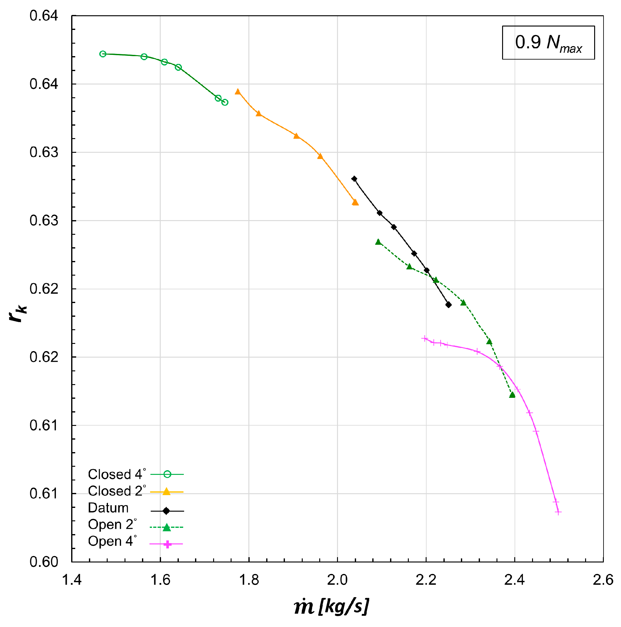
Figure 7 illustrates the degree of reaction for different diffuser vane angles at a rotational speed of 0.9Nmax. The degree of reaction of a centrifugal compressor is the ratio of the rotor static enthalpy rise to the stage stagnation enthalpy rise. The degree of reaction for a stage without inlet swirl can be calculated using the following equation:
As the diffuser vane angle decreases, the mass flow rate of the air passing through the impeller and so the velocity of the flow at the impeller outlet decrease. Also because of the backswept blade, the work input of the impeller increases with the decrease of the mass flow rate. As a result, the degree of reaction of the compressor increases with the decrease in the variable diffuser vane angle.
3.3. Discussion on Effects of the Variable Diffuser on the Impeller
Tamaki et al. [23] assumed in their work on matching between the impeller and diffuser that using different diffuser types does not affect the performance of the impeller and it keeps working with the same performance characteristic. Ziegler et al. [14] reported that the impact of vaned diffusers with different radial gaps and diffuser angles on the performance of the impeller is insignificant. These previous studies have been done on compressors with medium pressure ratio levels. We are not aware of any studies done on high pressure ratio compressors to investigate the effect of a variable diffuser on impeller performance.
As can be seen in Figure 6, at every speed, the performance characteristic curves of the impeller for different diffuser vane angles over the broad operating range form a uniform and continuous curve. This uniform trend implies the performance of the impeller is independent of the downstream vane diffuser system. To evaluate this, the average static pressure at impeller exit for different diffuser vane angles is studied.
Figure 8 shows the average static pressure at rotor–stator interface at 0.9Nmax. Figure 8 indicates that the impeller performance is the same over the operating range, for different diffuser vane angles. In order to investigate the flow condition at the impeller, various flow parameters at impeller exit for cases with different diffuser angles but the same mass flow rate are shown in Figure 9, Figure 10 and Figure 11. At this mass flow rate, the stage has different performance and operating conditions with various diffuser settings, but we can see that the flow conditions at impeller exit are the same. This confirms the independence of the impeller performance from the diffuser vane’s configuration.
Applying variable geometry diffuser technique significantly increases the operating range of the compressor. This makes the impeller to work stably in a much wider mass flow range than operating range of a conventional fixed geometry compressor with the same impeller. Since the performance of the impeller is independent of the diffuser, this technique can be used to study the performance of a new impeller at the design process and improve the accuracy of the matching between the impeller and diffuser in the operating conditions in question.
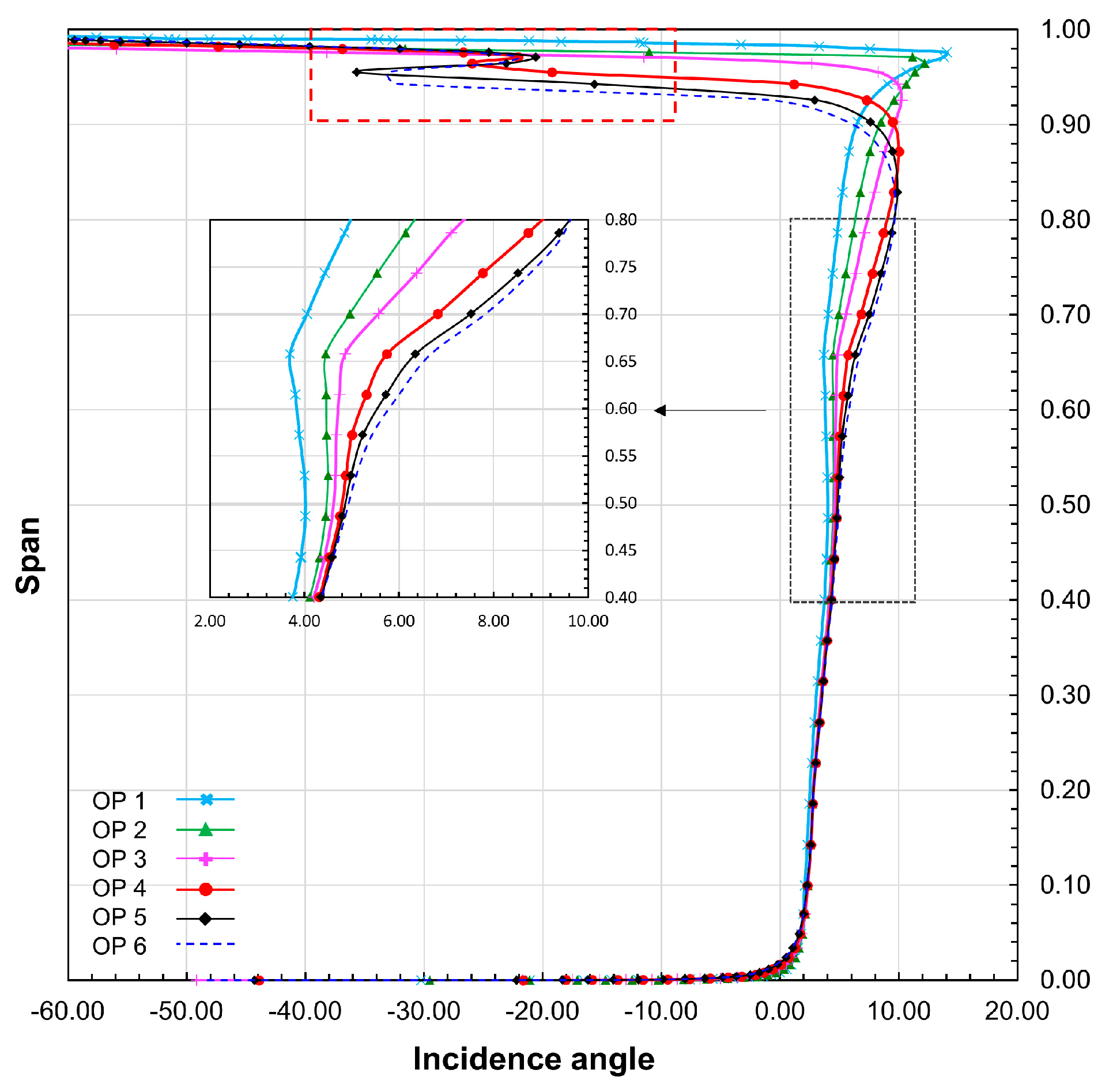
Although closing the diffuser significantly extends the stable operating range of the compressor by shifting the surge line to the lower mass flow rates, but working at low mass flow rates increases the incidence angle at the impeller leading edge. Figure 12 shows the pitch-averaged spanwise distribution of the incidence angle at the impeller leading edge six different operating points at 0.9Nmax. As shown in Table 2, operating points of 1 to 5 are for the “Closed 2°” case from choke to surge, respectively, and the operating point 6 is the choke point of the “Closed 4°” case. As the mass flow decreases, the incidence angle mid-span increases. This rise of the incidence angle decreases the stability of the tip region of the impeller leading edge to the point that flow separation will happen in the tip region, and a sudden drop of the incidence angle happens at spans of above 90% in operating point 2, which is at 1.82 kg/s mass flow rate.
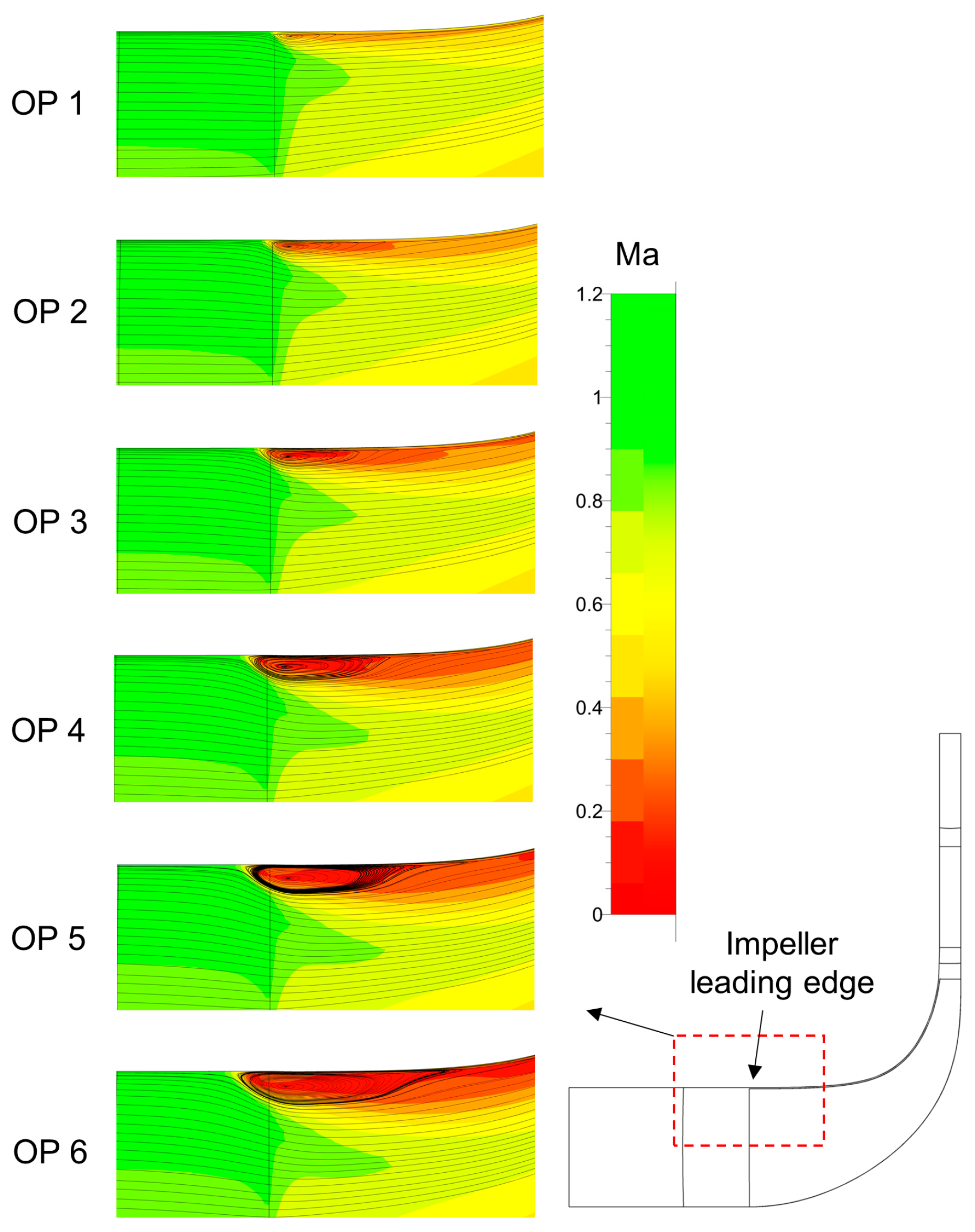
Figure 13 shows the pitch-averaged spanwise distribution of the relative Mach number at the tip region of the impeller leading edge superimposed by the streamlines for the mentioned operating points. As we can see, by an increase of the incidence angle due to the decline of the mass flow, the tip region becomes significantly unstable and flow recirculation vortex emerges. As the mass flow decreases further, the vortex grows and impinges the lower spans.
As the performance of the impeller is independent of the diffuser, at each speed there is a critical mass flow rate below which the impeller tip region will become unstable and flow separation emerges, regardless of the diffuser setting or the stage-wide working condition (such as choke or surge). Although at operating points below the critical mass flow rate, the stage might be working stably by closing the diffuser, the flow separation at the impeller tip region may damage the impeller due to increasing blade fatigue.
4. Conclusions
In this work, a variable diffuser vane was employed to improve the operating range and performance of a high pressure ratio centrifugal compressor. This study employed steady-state numerical simulations using Reynolds-averaged Navier-Stokes equations. Different diffuser vane rotation angles in a range from −6 to +6 were used to examine the effects on the performance of the compressor. The main conclusions can be summarized as follows.
- A variable vaned diffuser can significantly improve the operating range of centrifugal compressors. The effects of a variable vaned diffuser on high pressure ratio centrifugal compressors are verified. The stable operating range extended at different pressure ratio levels. There is an increase of 30.0% in the operating range of the current case for pressure ratios between 5.0 and 6.0. At higher rotational speeds, the main contributor to range extension is the shifting of the surge line to lower mass flow rates, which is due to the closing of the diffuser. At lower rotational speeds, changing the angle of diffuser vanes has minimal impact on the surge mass flow rate while it significantly shifts the choke line. At medium rotational speeds, both surge and choke lines shift by changing the diffuser vane angle. Thus, both contribute to extending the operating range.
- A variable vaned diffuser has a significant impact on the compressor’s efficiency. At higher rotational speeds, the choke mass flow of the diffuser is matched by that of the impeller. Thus, opening the diffuser at these speed neither shifts the choke line nor improves the efficiency. At lower rotation speeds, however, the impeller and diffuser are not matched and choking happens at the diffuser. Because of this, opening the diffuser extends the operating range by shifting the choke line to higher mass flows and increases the efficiency of the stage by up to 4.5% at 0.8Nmax by improving the matching between impeller and diffuser.
- The impeller performance is independent of the modification in diffuser vane angle. For every rotation speed, the component performance of the impeller is a consistent curve even for diffusers with different vane angles. A change in the diffuser settings did not change the flow conditions at the impeller exit.
- Centrifugal impellers coupled with variable diffusers are able to operate in a wide range of mass flow rates. This is proposed as a general method to study the behavior of the impeller over a wide range of mass flow rates. By applying this approach, a critical point in the operating range of the impeller from stability was found.
- At each rotation speed, there is a certain mass flow rate for the impeller where the incidence angle at the impeller leading edge reaches a critical point. Because of the high incidence angle, instability and separation vortexes will arise in the near-tip region of the impeller as the mass flow rate decreases. This critical point is independent of diffuser settings and stage-wide working conditions such as choke or surge, which means even when the stage is in a stable condition there might be large separation vortexes at the near-tip region of the impeller. The instability in the impeller will grow larger with a further decrease in the mass flow rate.
Acknowledgments
We would like to thank the National Natural Science Foundation of China (Grant No. 51176087) for supporting this research.
Author Contributions
Mohsen Ebrahimi acquired the data and wrote the paper; Qiangqiang Huang, Xiao He and Xinqian Zheng revised the paper and offered useful suggestions to write the paper; in addition, Qiangqiang Huang assisted in analyzing the data.
Conflicts of Interest
The authors declare no conflict of interest.
Nomenclature
| A | passage area |
| h | enthalpy |
| mass flow rate | |
| choke mass flow rate | |
| surge mass flow rate | |
| Ma | Mach number |
| Nmax | maximum rotational speed of the impeller |
| P | pressure |
| T | temperature |
| r | distance in the radial direction |
| rk | degree of reaction |
| y+ | normalized wall distance |
| Z | number of blades |
| γ | specific heat ratio = 1.4 (constant) for air in this paper |
| η | total-to-total isentropic efficiency |
| π | total-to-total pressure ratio |
| ω | loss coefficient |
Subscripts
| 1 | impeller inlet |
| 2 | impeller exit |
| 3 | rotor-stator interface |
| 4 | diffuser inlet |
| 5 | diffuser outlet |
| 7 | outlet |
| I | impeller |
| D | diffuser |
| S | stage |
| s | static |
| t | total |
References
- Krain, H. Review of Centrifugal Compressor’s Application and Development. J. Turbomach. 2005, 127, 25–34. [Google Scholar] [CrossRef]
- Bents, D.J.; Mockler, T.; Maldonado, J.; Harp, J.L., Jr.; King, J.F.; Schmitz, P.C. Propulsion System for Very High Altitude Subsonic Unmanned Aircraft; NASA Technical Briefs DRC-98-61; NASA Lewis Research Center: Cleveland, UT, USA, 1998.
- Bettner, J.L.; Blandford, C.S.; Rezy, B.J. Propulsion System Assessment for Very High UAV under ERAST; NASA CR-195469; NASA: Cleveland, UT, USA, 1995.
- Rodgers, C. Turbocharging a high altitude UAV C.I. engine. In Proceedings of the 37th Joint Propulsion Conference and Exhibit, Salt Lake City, UT, USA, 8–11 July 2001; American Institute of Aeronautics and Astronautics: Reston, VA, USA, 2001. [Google Scholar]
- Rodgers, C. Flow Ranges of 8.0:1 Pressure Ratio Centrifugal Compressors for Aviation Applications. In Proceedings of the ASME Turbo Expo 2005 Parts A and B, Reno, NV, USA, 6–9 June 2005; Volume 6, pp. 801–811. [Google Scholar]
- Cumpsty, N.A. Compressor Aerodynamics, 2nd ed.; Krieger: Malabar, FL, USA, 2004. [Google Scholar]
- Rodgers, C.; Brown, D. A Performance Autopsy of Three Centrifugal Compressors for a Small Gas Turbine. In Proceedings of the ASME Turbo Expo 2010: Power for Land, Sea, and Air (Volume 5: Industrial and Cogeneration; Microturbines and Small Turbomachinery; Oil and Gas Applications; Wind Turbine Technology), Glasgow, UK, 14–18 June 2010; pp. 239–247. [Google Scholar]
- Zheng, X.; Zhang, Y.; Yang, M.; Bamba, T.; Tamaki, H. Stability Improvement of High-Pressure-Ratio Turbocharger Centrifugal Compressor by Asymmetrical Flow Control—Part II: Nonaxisymmetrical Self-Recirculation Casing Treatment. J. Turbomach. 2012, 135, 21007. [Google Scholar] [CrossRef] [PubMed]
- Li, P.-Y.; Gu, C.-W.; Song, Y. A New Optimization Method for Centrifugal Compressors Based on 1D Calculations and Analyses. Energies 2015, 8, 4317–4334. [Google Scholar] [CrossRef]
- Moosania, S.; Zheng, X. Comparison of Cooling Different Parts in a High Pressure Ratio Centrifugal Compressor. Appl. Sci. 2016, 7, 16–28. [Google Scholar] [CrossRef]
- Whitfield, A. Review of Variable Geometry Techniques Applied to Enhance the Performance of Centrifugal Compressors. In Proceedings of the International Compressor Engineering Conference, West Lafayette, IN, USA, 25–28 July 2000; pp. 63–70. [Google Scholar]
- Simon, H.; Wallmann, T.; Mönk, T. Improvements in Performance Characteristics of Single-Stage and Multistage Centrifugal Compressors by Simultaneous Adjustments of Inlet Guide Vanes and Diffuser Vanes. J. Turbomach. 1987, 109, 41–47. [Google Scholar] [CrossRef]
- Salvage, J.W. Development of a Centrifugal Compressor With a Variable Geometry Split-Ring Pipe Diffuser. J. Turbomach. 1999, 121, 295–304. [Google Scholar] [CrossRef]
- Ziegler, K.U.; Gallus, H.E.; Niehuis, R. A Study on Impeller-Diffuser Interaction—Part I: Influence on the Performance. J. Turbomach. 2003, 125, 173–182. [Google Scholar] [CrossRef]
- Huang, Q.; Zheng, X. Potential of variable diffuser vanes for extending the operating range of compressors and for improving the torque performance of turbocharged engines. Proc. Inst. Mech. Eng. Part D J. Automob. Eng. 2017, 231, 555–566. [Google Scholar] [CrossRef]
- Zheng, X.; Huang, Q. Potential of the range extension of compressors with a variable inlet prewhirl for automotive turbocharged engines with an ultra-high-power density. Proc. Inst. Mech. Eng. Part D J. Automob. Eng. 2015, 229, 1959–1968. [Google Scholar] [CrossRef]
- Zsiga, N.; Voser, C.; Onder, C.; Guzzella, L. Intake Manifold Boosting of Turbocharged Spark-Ignited Engines. Energies 2013, 6, 1746–1763. [Google Scholar] [CrossRef]
- Gwehenberger, T.; Thiele, M.; Seiler, M.; Robinson, D. Single-Stage High-Pressure Turbocharging. In Proceedings of the ASME Turbo Expo 2009: Power for Land, Sea, and Air (Volume 5: Microturbines and Small Turbomachinery; Oil and Gas Applications), Orlando, FL, USA, 8–12 June 2009; pp. 103–113. [Google Scholar]
- Jameson, A. Time Dependent Calculations Using Multigrid, with Applications to Unsteady Flows Past Airfoils and Wings. In Proceedings of the AIAA 10th Computational Fluid Dynamics Conference, Honolulu, HI, USA, 24–26 June 1991; p. 14. [Google Scholar]
- Spalart, P.R.; Allmaras, S.R. A one-equation turbulence model for aerodynamic flows. La Rech. Aerosp. 1994, 1, 5–21. [Google Scholar]
- He, X.; Zheng, X.; Wei, J.; Zeng, H. Investigation of Vaned Diffuser Splitters on the Performance and Flow Control of High Pressure Ratio Centrifugal Compressors. In Proceedings of the ASME Turbo Expo 2016: Turbomachinery Technical Conference and Exposition (Volume 2D: Turbomachinery), Seoul, Korea, 13–17 June 2016; p. V02DT42A008. [Google Scholar]
- Casey, M.; Rusch, D. The Matching of a Vaned Diffuser With a Radial Compressor Impeller and Its Effect on the Stage Performance. J. Turbomach. 2014, 136, 121004. [Google Scholar] [CrossRef]
- Tamaki, H.; Nakao, H.; Saito, M. The Experimental Study of Matching Between Centrifugal Compressor Impeller and Diffuser. J. Turbomach. 1999, 121, 113–118. [Google Scholar] [CrossRef]
- Dixon, S.L.; Hall, C.A. Centrifugal Pumps, Fans, and Compressors. In Fluid Mechanics and Thermodynamics of Turbomachinery; Elsevier: Amsterdam, The Netherlands, 2014; pp. 265–317. [Google Scholar]
Figure 1.
Impeller and diffuser grid.
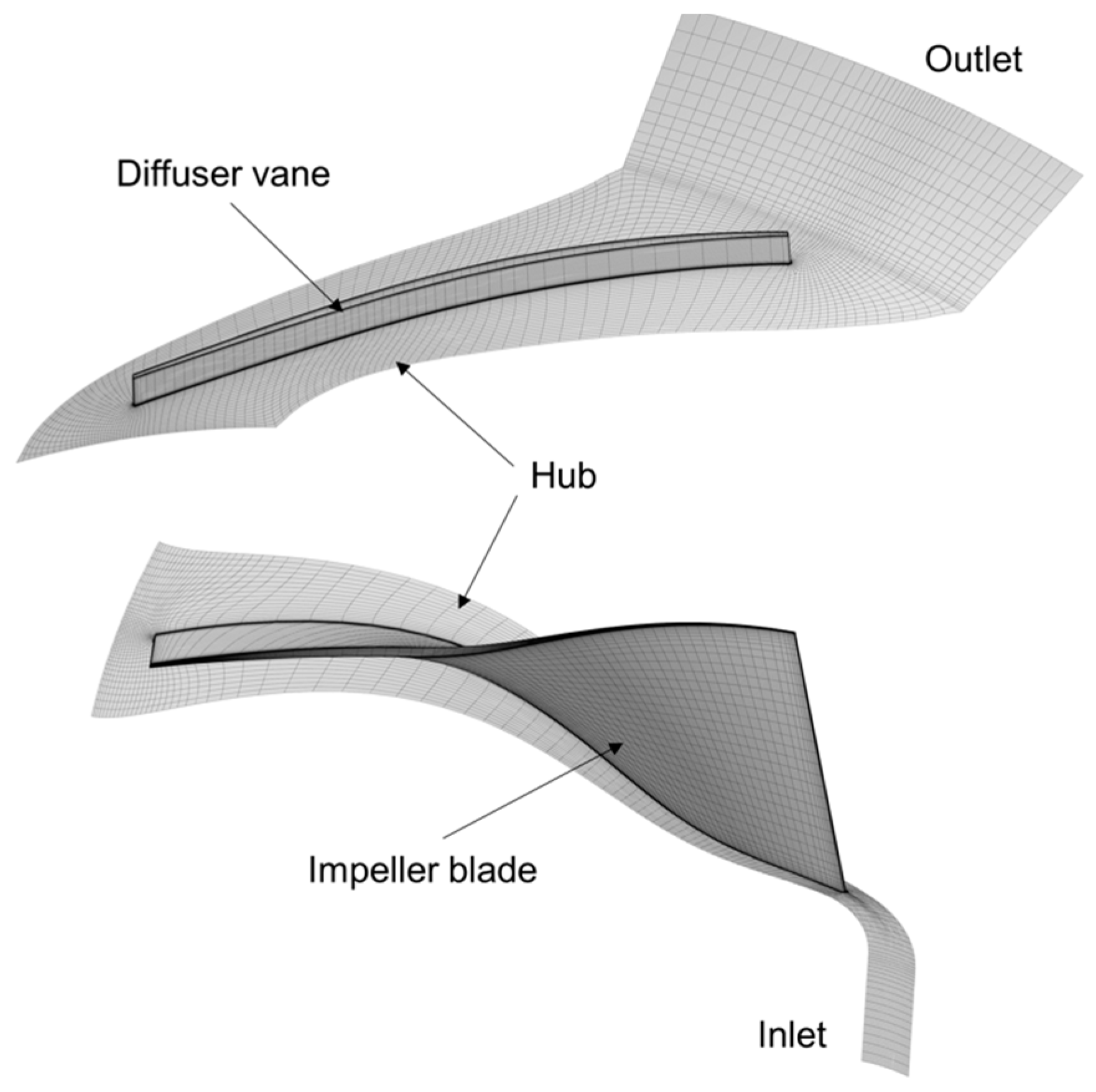
Figure 2.
The compressor impeller together with the diffuser vanes at different angles.
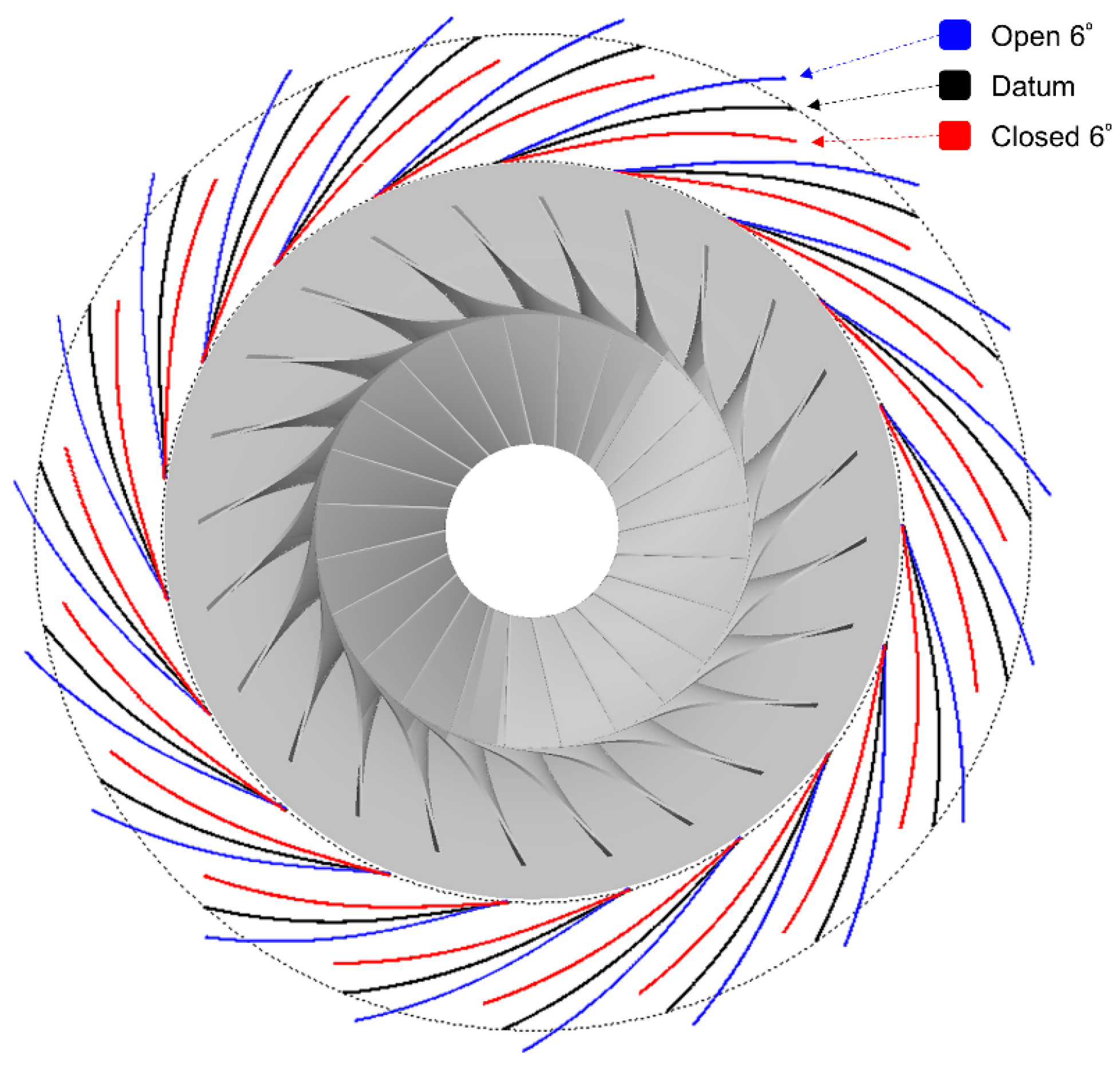
Figure 3.
Compressor map for different diffuser vane angles and rotational speeds. Extended range of the compressor is highlighted.
Figure 3.
Compressor map for different diffuser vane angles and rotational speeds. Extended range of the compressor is highlighted.

Figure 4.
Comparison between the SOR of the datum compressor and variable diffuser compressor for different pressure ratios.
Figure 4.
Comparison between the SOR of the datum compressor and variable diffuser compressor for different pressure ratios.

Figure 5.
Compressor efficiency performance for various diffuser vane angles and rotational speeds. (a) Nmax; (b) 0.9Nmax; (c) 0.8Nmax; (d) 0.6Nmax.
Figure 5.
Compressor efficiency performance for various diffuser vane angles and rotational speeds. (a) Nmax; (b) 0.9Nmax; (c) 0.8Nmax; (d) 0.6Nmax.


Figure 6.
Diffuser loss coefficient and adiabatic efficiency of the impeller at different rotational speeds. (a) Nmax; (b) 0.9Nmax; (c) 0.8Nmax; (d) 0.6Nmax
Figure 6.
Diffuser loss coefficient and adiabatic efficiency of the impeller at different rotational speeds. (a) Nmax; (b) 0.9Nmax; (c) 0.8Nmax; (d) 0.6Nmax

Figure 7.
Degree of reaction for different diffuser vane angles at 0.9Nmax.

Figure 8.
Average static pressure at the rotor–stator interface for different diffuser vane angles.

Figure 9.
Static pressure contours at the rotor–stator interface for different diffuser vanes angles at 2.25 kg/s mass flow rate.
Figure 9.
Static pressure contours at the rotor–stator interface for different diffuser vanes angles at 2.25 kg/s mass flow rate.
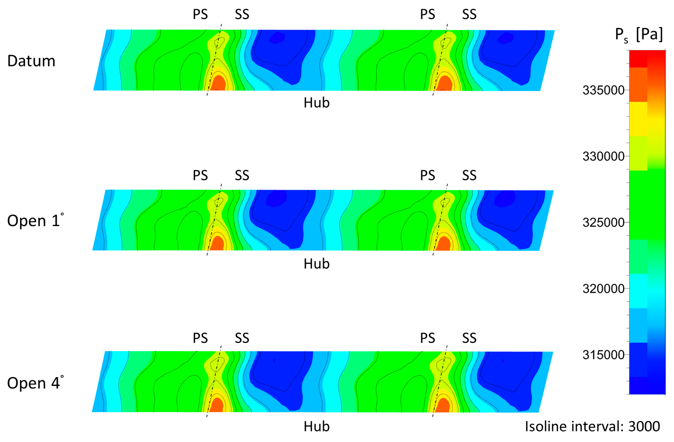
Figure 10.
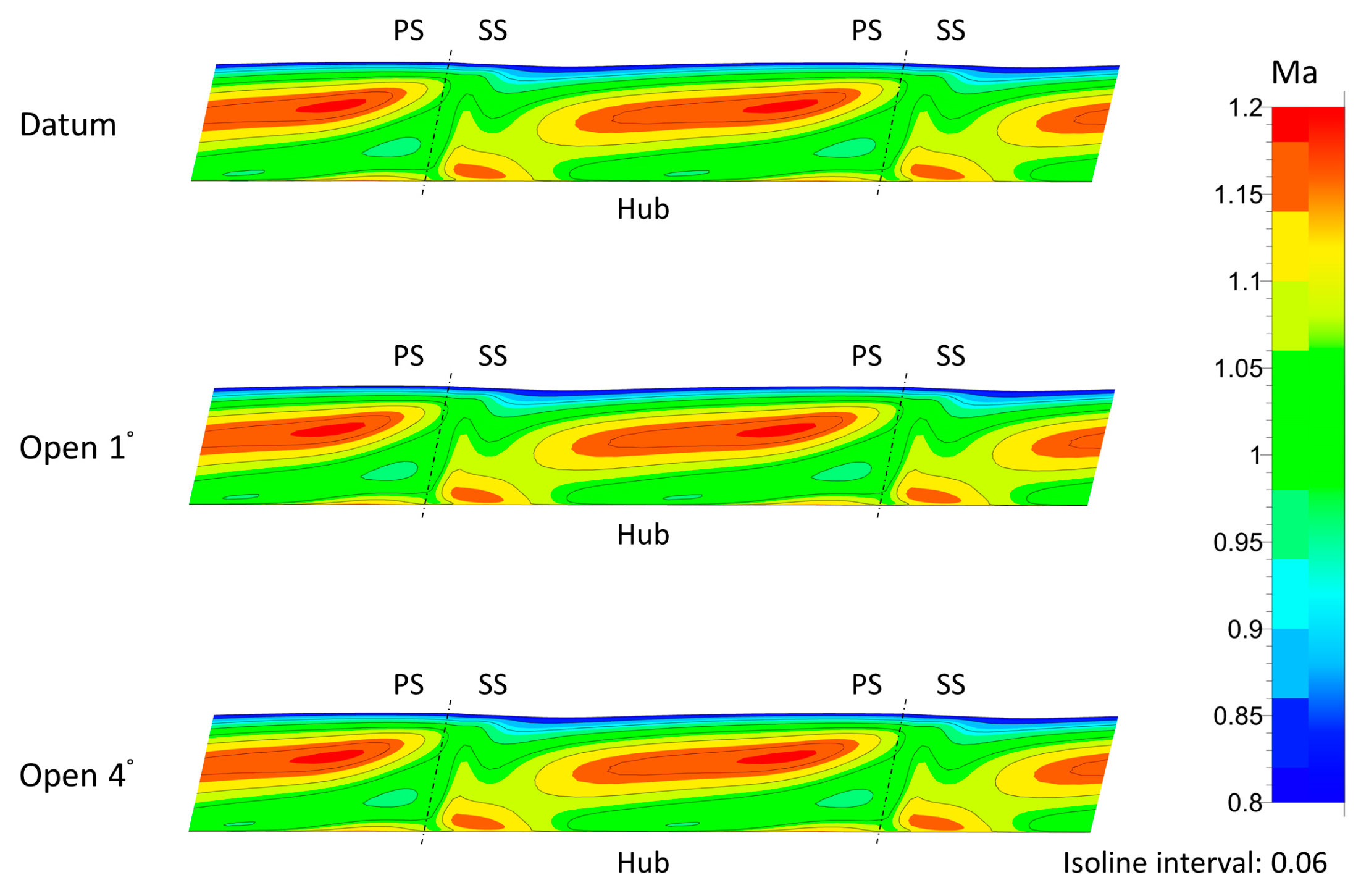
Absolute Mach number contours at the rotor–stator interface for different diffuser vanes angles at 2.25 kg/s mass flow rate.
Figure 10.
Absolute Mach number contours at the rotor–stator interface for different diffuser vanes angles at 2.25 kg/s mass flow rate.

Figure 11.
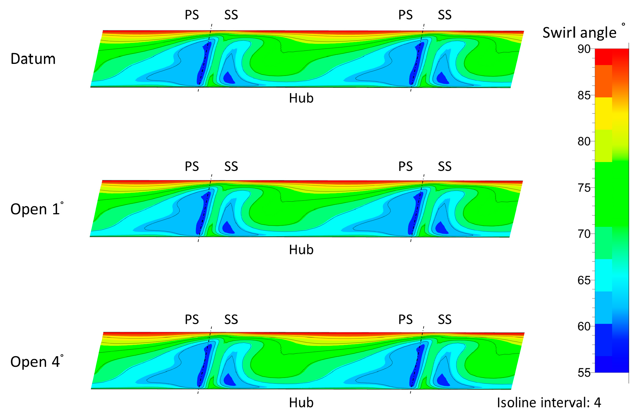
Swirl angle contours at the rotor-stator interface for different diffuser vanes angles at 2.25 kg/s mass flow rate.
Figure 11.
Swirl angle contours at the rotor-stator interface for different diffuser vanes angles at 2.25 kg/s mass flow rate.

Figure 12.
Pitch averaged spanwise distribution of incidence angle at leading edge of the impeller.

Figure 13.
Pitch-averaged spanwise contour of the relative Mach number at tip of the impeller leading edge superimposed with streamlines.
Figure 13.
Pitch-averaged spanwise contour of the relative Mach number at tip of the impeller leading edge superimposed with streamlines.

Table 1.
Compressor specifications.
| Impeller | ||
| Number of blades | ZI | 24 |
| Maximum rotational speed | Nmax (r/min) | 52,440 |
| Diffuser | ||
| Number of Vanes | ZD | 19 |
| Area ratio | A5/AThroat | 2.0 |
| Normalized leading edge radius | r4/r2 | 1.10 |
| Normalized trailing edge radius | r5/r2 | 1.48 |
© 2017 by the authors. Licensee MDPI, Basel, Switzerland. This article is an open access article distributed under the terms and conditions of the Creative Commons Attribution (CC BY) license (http://creativecommons.org/licenses/by/4.0/).
Share and Cite
MDPI and ACS Style
Ebrahimi, M.; Huang, Q.; He, X.; Zheng, X. Effects of Variable Diffuser Vanes on Performance of a Centrifugal Compressor with Pressure Ratio of 8.0. Energies 2017, 10, 682. https://doi.org/10.3390/en10050682
AMA Style
Ebrahimi M, Huang Q, He X, Zheng X. Effects of Variable Diffuser Vanes on Performance of a Centrifugal Compressor with Pressure Ratio of 8.0. Energies. 2017; 10(5):682. https://doi.org/10.3390/en10050682
Chicago/Turabian StyleEbrahimi, Mohsen, Qiangqiang Huang, Xiao He, and Xinqian Zheng. 2017. "Effects of Variable Diffuser Vanes on Performance of a Centrifugal Compressor with Pressure Ratio of 8.0" Energies 10, no. 5: 682. https://doi.org/10.3390/en10050682
Note that from the first issue of 2016, this journal uses article numbers instead of page numbers. See further details here.