1. Introduction
The fossil energy crisis has expedited the development of renewable power generation (RPG) [
1]. The microgrid (MG), an important part of the future smart grid, can flexibly organize the RPG integration into the power system [
2,
3,
4,
5]. Typical RPGs such as wind and photovoltaic generation have high intermittent and fluctuating natures, which deteriorate the stability of the power system [
6]. Consequently, energy storage systems (ESSs) are essential in the MG to sustain the output power, voltage, and frequency [
7,
8,
9]. The superconducting magnetic energy storage (SMES) system is a promising ESS in MG applications due to its significant life cycle and power density advantages [
10,
11,
12]. The SMES system has been used in MG for the power smoothing, load following, power oscillation damping, power factor correction, and dynamic voltage improvement [
13]. In this study, SMES is applied in MG for the power smoothing in the grid-connected (GC) mode as well as the frequency and voltage regulation in the islanded mode.
The power conditioning system (PCS) is used to transfer the energy between the superconducting coil and the AC grid. The power switch of the PCS can be the half-controlled device thyristor or the fully-controlled device such as insulated gate bipolar transistor (IGBT). The PCS topology is divided into two types: voltage source converter (VSC), and current source converter (CSC) [
2]. In this study, and IGBT switched VSC-based topology is adopted for SMES due to the mature technology and wide applications.
The control performance of SMES mainly relies on a PCS control strategy [
14]. The VSC-based SMES system has relatively high nonlinear and coupling characteristic because the PCS of a SMES system includes the DC/DC chopper and VSC. Robustness should be an important consideration in any SMES system to maintain its stability due to its high nonlinear and coupling characteristics [
15,
16]. In the real implementation, the model mismatch is inevitable due to the parameter drift and uncertainty [
17,
18]. In some cases, the structural parameters of the SMES converter may actively improve the certain performance such as the output impedance of the converter (the switching ripple filters). A controller with poor robustness might substantially undermine the performance in the SMES applications [
18,
19] whereas a controller with strong robustness can maintain satisfactory performance and prevent the redesign process. Conventionally, the proportional–integral (PI) strategy is employed to control the PCS of SMES. However, the PI-based SMES system might present an unsatisfactory robustness [
20] because the SMES and MG systems are both complex nonlinear and strongly coupling systems [
21]. Since the partially linearized model of the SMES system is usually used to design the PI controller, the PI method can only obtain the local stability and the respectable performance near the equilibrium point [
20]. When the operation points deviate from the balance point, the conventional PI method might achieve poor performance, and even become unstable. To solve the problem, in [
22], the authors have proposed an H
2/H
∞-based robust PI control method for the SMES system. However, this approach employs the particle swarm optimization (PSO) strategy to adjust the PI parameters, which increases the computation and complexity of the SMES control system significantly.
Nonlinear control methods such as hysteresis, sliding, and fuzzy control methods, which can improve the robustness of the system compared with the conventional PI method [
23], have been studied in the converter control areas [
24,
25,
26]. Hysteresis control is simple to implement with good transient performance and robustness, but the unfixed switching frequency may increase the difficulty of the filter design. Sliding control is insensitive to the parameter variation and disturbance, but nonetheless, chattering problems will deteriorate the control performance. Fuzzy control can be applied to the complicated system to enhance the control robustness. However, it presents low steady performance, and the design is not systematic. Due to their respective defects, these methods are subject to limitations when applied in a SMES control system. Recently, an advanced nonlinear control strategy, the so-called energy shaping passivity (ESP)-based control method, has drawn the interest of many researchers [
27,
28,
29]. The property of passivity, a special case of the system’s dissipation characteristics, means that the energy injected from the outside is always less than the energy accumulated in the system. The passivity is an important concept in control theory because it corresponds to the Lyapunov stability of the system. The passivity-based control (PBC) is a class of the advanced control using an expected energy storage function and the damping injection, which guarantees the system’s passivity to achieve control stability. Unlike the conventional control concept which focuses on the signal, the PBC considers the controller design from the viewpoint of the energy which is the essential attribute of the physical system. Therefore, some desired control properties can be achieved easily such as the global stability, strong robustness, etc. Compared with the “classical” PBC which is usually called the Lyapunov control, the ESP-based control is proved to be superior because it retains the Lagrangian structure of the system [
30]. Energy shaping (ES) is the power configuration process to stabilize the closed-loop control system at the expected equilibrium point. Interconnection and damping assignment (IDA) strategy, which have low control complexity and outstanding performance, can be considered as an effective implementation of ES [
31]. In the IDA methodology, the structure of the expected system is firstly described by the port-controlled Hamiltonian (PCH) equations. Then the energy of the closed-loop system is configured to match the structure of the scheme. Finally, the control input can be achieved by solving the resulting simultaneous equations. The advantage to ESP-based method over the other nonlinear regulation approaches lies in the full consideration of the system interconnection features, which results in a straightforward controller implementation [
32]. In contrast to the traditional PI control, the ESP-based approach provides better transient control performance. Moreover, the ESP-based approach can remain stable and robust over a wider operation range than PI control [
33]. Consequently, the ESP-based control method can achieve superior robustness performance in SMES application in comparison with the conventional PI method.
The ESP-based method has been studied in the areas of mechanics, astronautics, robotics, and power electronics [
33,
34,
35,
36,
37,
38,
39,
40]. Recently, the ESP-based strategy has been studied for power converter control applications such as AC/DC converters [
36], motor drive converters [
37], battery charging converters [
38], GC inverters [
39], and active power filters (APFs) [
40]. Although the ESP-based controllers are designed and can get good control effect, there are still some limitations in these studies. References [
36,
37,
38,
39] only focused on the control performance of ESP-based strategy itself and did not compare the performance of ESP-based method with that of some other approaches. Besides, the conditions of parameter variations, which are very common in the practical application, were not examined in [
37,
38,
39]. Additionally, the PI regulator proposed in [
40] for the comparison has an unclear design basis and a weak control effect.
So far, no ESP-based strategy has been proposed for the SMES control. In this study, the ESP-based method is implemented to control the PCS of the SMES for robustness improvement of the SMES system. In particular, the robustness to the uncertainties of the converter parameters is considered in this paper. Furthermore, a step-by-step ESP-based design method including the robustness considerations for the SMES system is proposed, which might provide a useful reference for other ESP-based researches. The IDA strategy and integral operation incorporate organically to ensure the outstanding performance even under the model mismatch circumstances. The robustness of the ESP-based SMES controller is compared with that of the conventional PI controller. Besides, the DC current in the superconducting coil is also compared between ESP-based and PI control system to evaluate the efficiency of ESP-based SMES control system. The remainder of this paper is organized as follows:
Section 2 presents a stepwise ESP-based regulator design strategy which is used for the current control loop of SMES system with the consideration of the robustness issue.
Section 3 provides the example MG system and the overall regulation scheme of SMES system for MG application.
Section 4 offers the simulation results of the ESP-based method and compares the robustness of the ESP-based and PI methods.
Section 4 also provides some discussions of the simulation results.
Section 5 presents the experimental results. Finally,
Section 6 concludes this study.
2. Design of the Current Control Loop for SMES System Using ESP-Based method
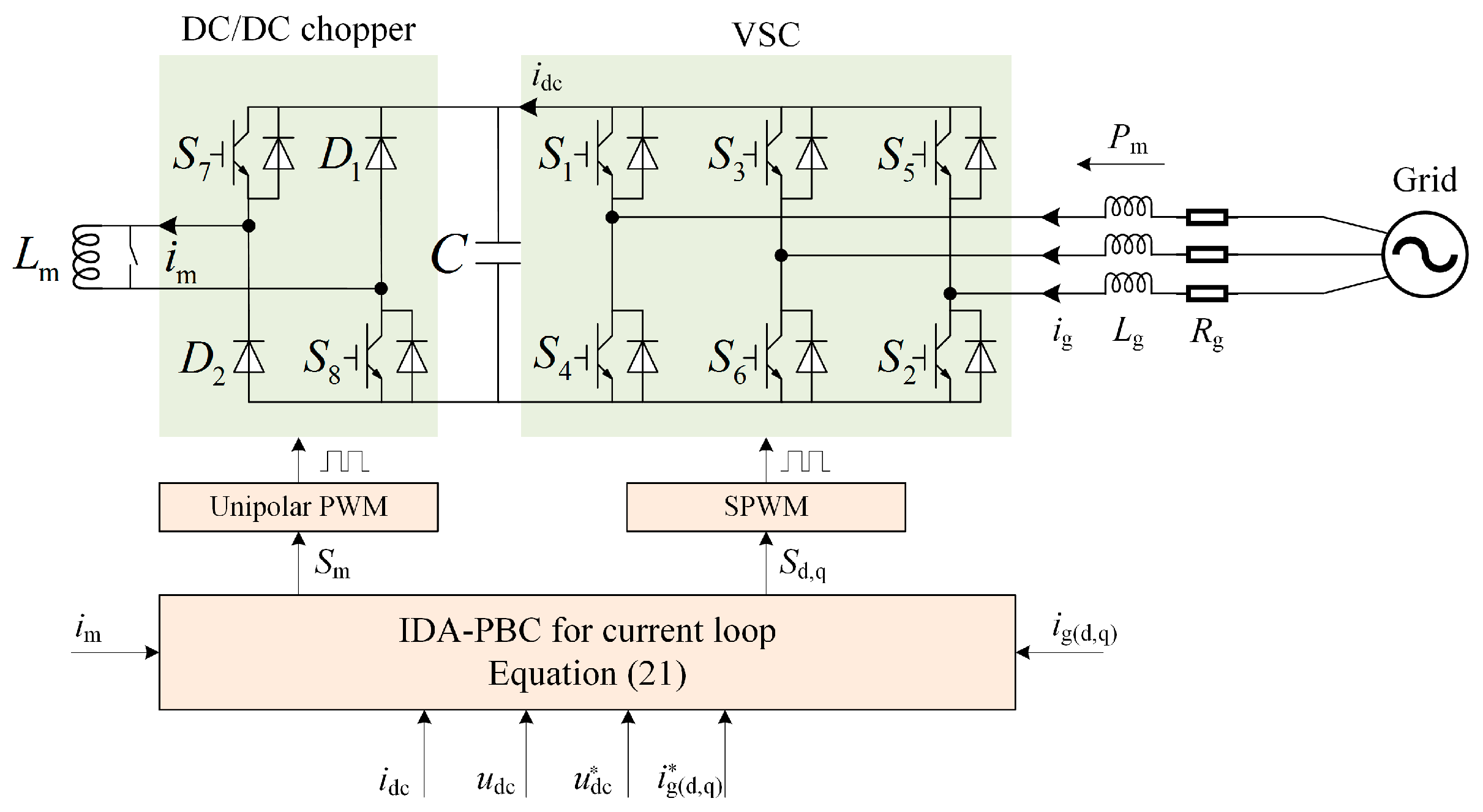
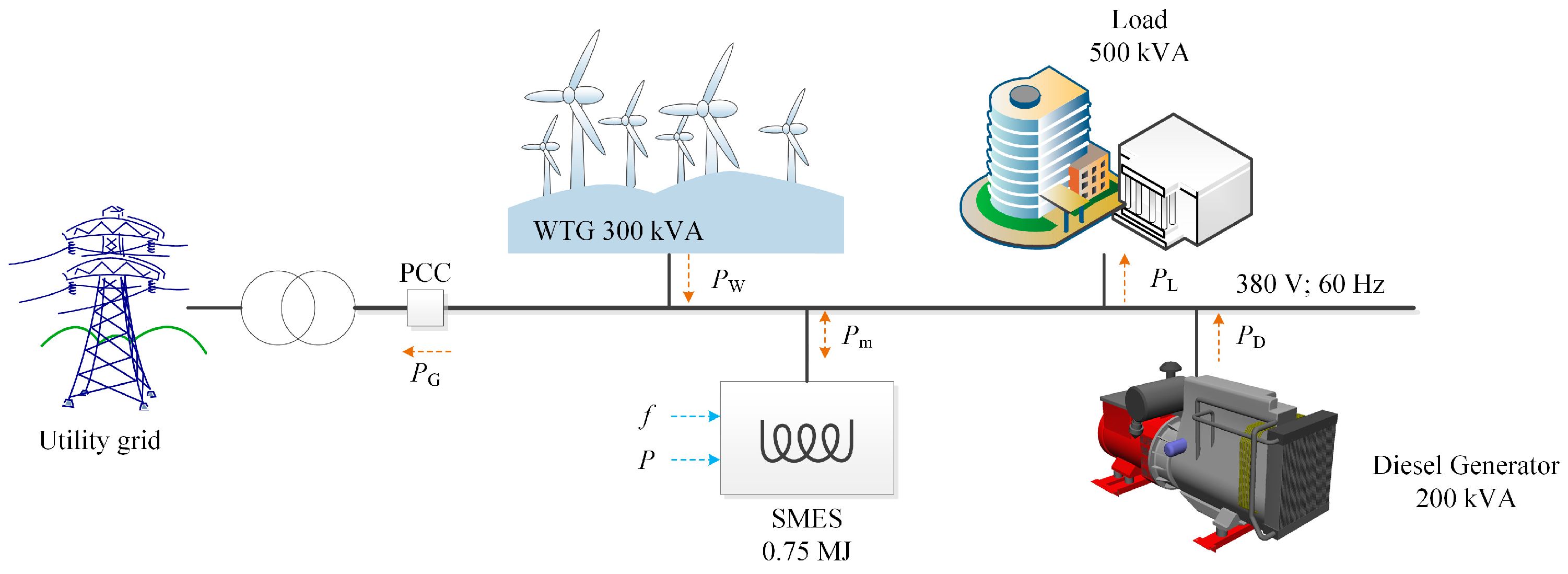
Figure 1 depicts the SMES topology utilized in this study. The superconducting coil is firstly linked to the DC capacitor by a bidirectional DC/DC chopper and then interfaced to the AC MG by a VSC. This topology is well known as VSC-based SMES. VSC can independently control the real and reactive powers transfer.
In
Figure 1,
S stands for the IGBTs, and
D is the power diode. It is assumed that the direction flowing into the SMES is positive both for the SMES current
ig and power
Pm. The superconducting coil charges and discharges through the bidirectional DC/DC converter to maintain a stable DC capacity voltage. When the DC voltage is controlled to be constant, energy releasing from the SMES is the sum of system losses and the energy injected into the grid.
In this study, the ESP-based method used in the current loop of the SMES system is proposed to contain both DC/DC and VSC converters for the robustness improvement. As shown in
Figure 1, the ESP-based control directly calculates the duty ratio of the converter to control the SMES. The detailed ESP-based design process including the robustness considerations for SMES system consists of the following four steps.
2.1. The Establishment of Mathematical Model
The design of ESP-based control method requires the mathematical model of the VSC-based SMES system. To facilitate the analysis and control, the VSC model is represented in the two-phase synchronous rotating coordinate (d-q frame). Then, the mathematical model of SMES system depicted in
Figure 1 is given as in Equation (1):
where
s represents the duty cycle of the system. In particular,
sd and
sq are for the VSC control, and
sm is for the DC/DC chopper control. To simplify the analysis,
sm is defined as in (2):
Meanwhile, in the ESP-based strategy, the PCH model of the system should be established as the following standard form:
where
R(
x) describes the damping properties of the dissipative system, and it should meet
;
J(
x) and
g(
x) can depict the interconnect characteristics of the physical system.
H(
x) is the energy function that corresponds to the storage energy of the system.
By using (1) to (3), the PCH model of the VSC-based SMES system is given as below:
2.2. The Determination of the Equilibrium Points
The IDA energy-shaping method is employed in this study because it is easy to implement and the control performance is satisfactory. The structure of closed-loop SMES control system should be configured in the following PCH equation:
The matrices with the subscript
d are the desired parameters in the feedback control system, whereas the matrices with the subscript
a mean the functions awaiting to be determined, which correspond to the parts introduced by the feedback regulation. For example,
Ha(
x) describes the energy introduced by the regulation. Based upon IDA strategy, the expected Hamilton energy function
Hd(
x) should adapt the configured structure of the closed-loop control system with the minimum value at the equilibrium point
x*. Furthermore, the balance positions of the closed-loop control system can be gained by:
Based on the instantaneous power equations in the d-q frame, the current references of VSC can be obtained:
The DC voltage should be controlled stably at the reference to maintain the proper operation of VSC. should be high enough to ensure the tracking ability of the VSC. Meanwhile, the selection of should also consider the withstand voltage capability of the IGBTs.
2.3. The Configuration of Energy Shaping and Stability Analysis
In the closed-loop control system, the desired Hamilton energy function which should meet the Equation (7) to ensure the convergence of balance points is given in Equation (9):
Energy shaping is the process to make the closed-loop system reach the expected energy
Hd by controlling the injected energy
Ha. By combining the (3) and (6), it can be obtained by:
Equation (10) is a significant constraint in the implementation of the ESP-based method. By choosing suitable indefinite matrices Ja and Ra, the expected duty ratio for PCS in the closed-loop control system can be achieved by solving Equation (10). With the control law obtained by Equation (10), the energy of the closed-loop system will converge to the expected Hd value. The system will be stable at the balance points, and the energy shaping is achieved.
The design method for indefinite matrices in the ESP-based method is provided in [
30]. For the purpose of facilitating the design and decreasing the complexity of the ESP-based controller, here the indefinite matrices are determined as:
By substituting Equations (5), (6), (9) and (11) into (10), the intermediate variable
can be eliminated. The following equation can be acquired:
Stability is an essential consideration for the regulator design. The Lyapunov second theorem is convenient to check the stability of the nonlinear system like ESP-based SMES.
Hd can be chosen as the Lyapunov function because it describes the energy features of the closed-loop control system with the nonnegative characteristic and just achieves the zero value at the balance position. This choice can substantially decrease the complexity of stability evaluation, which is a significant advantage for the ESP-based control strategy. Based on the Lyapunov criterion, the stability of the controller can be judged by the derivative of
Hd showed in Equation (13):
The derivation process of Equation (13) employs two mathematical conditions. Firstly, Jd has the antisymmetric feature. Therefore, it can be known Secondly, Rd has the nonnegative and symmetric characteristics. From Equation (13), the derivative of Hd is non-positive and just get the zero value at the balance position. Consequently, the equilibrium position gains the asymptotical stability. Moreover, it can be easily concluded that if The system can acquire a large-scale asymptotic stability near the balance position, which is another outstanding merit of the ESP-based control.
2.4. Introducing the Integrators
The ESP-based method configures of the structure and energy of the system with the aid of the PCH model. Parameter variation and the external noise may introduce the steady-state performance problem to the ESP-based method such as the existence of the steady error. For the purpose of dealing with this issue, the ESP-based control can introduce the integrators in the IDA strategy to achieve the outstanding static performance even in the situation of the model mismatch and the interference [
41]. The duty ratios are functioning to the SMES converter regulation. The original location of
sm lies in the interconnection matrix
J. It should be transferred to the input vector
u in the new PCH model for the SMES system as shown below:
The subscript n means new. It is worth noting that the state variable Lmim is ignored in the new PCH model. The reason is that the expected controlled variables are igd, igq, and udc. im is only the intermediate variable in the model and can be omitted in the integral combination.
It can be noticed in Equation (16) that
represents the differences between the actual value and the expected value for the control variables. Defining
, a new part can be introduced as:
where
is the integral coefficient matrix, and
is an introduced integrator array.
When
, the static error will be eliminated even under the parameter uncertainty situations. New parts introduced in the model are defined as:
The ESP-based SMES PCH model with the integrator extension can be built as in Equation (19):
Reference [
41] has proposed and proved the integral stability theorem for the IDA strategy. Based on this theorem, the integrator extension of IDA methodology in the PCH system will not change any stability characteristic of the control system. Furthermore, the steady errors can be eliminated by:
By taking the related variables into Equation (20), it can be finally acquired:
The determination of just needs to consider the magnitude the steady error. Equation (21) is the control law in the ESP-based method. The duty ratio of the converter can be directly calculated by the sampling value of the related variables. sd and sq are used to control the VSC, while sm is used to regulate the DC chopper. It can be concluded from Equation (21) that the ESP-based control strategy is simply implemented due to the direct calculation.
3. Test Microgrid System and SMES Control System for Microgrid Application
In this study, an AC MG consisting of the wind generation (WG), DG, load, and SMES is employed as an example. The constitution and parameters of the example MG system for the test are illustrated in
Figure 2. The rated line voltage RMS value is 380 V and the rated frequency is 60 Hz. A constant-speed wind turbine generator (WTG) is employed in the simulation with the expected output power of 300 kW. The capacity of the DG is 200 kVA. The 500 kW resistor load is considered in the simulation. The inductance value of the superconductive coil is 1.5 H, and the initial coil current is 1000 A. The forward direction of the primary power flow in MG system is also provided in
Figure 2.
has the reversible power flow characteristics, and the charge is determined to be forward.
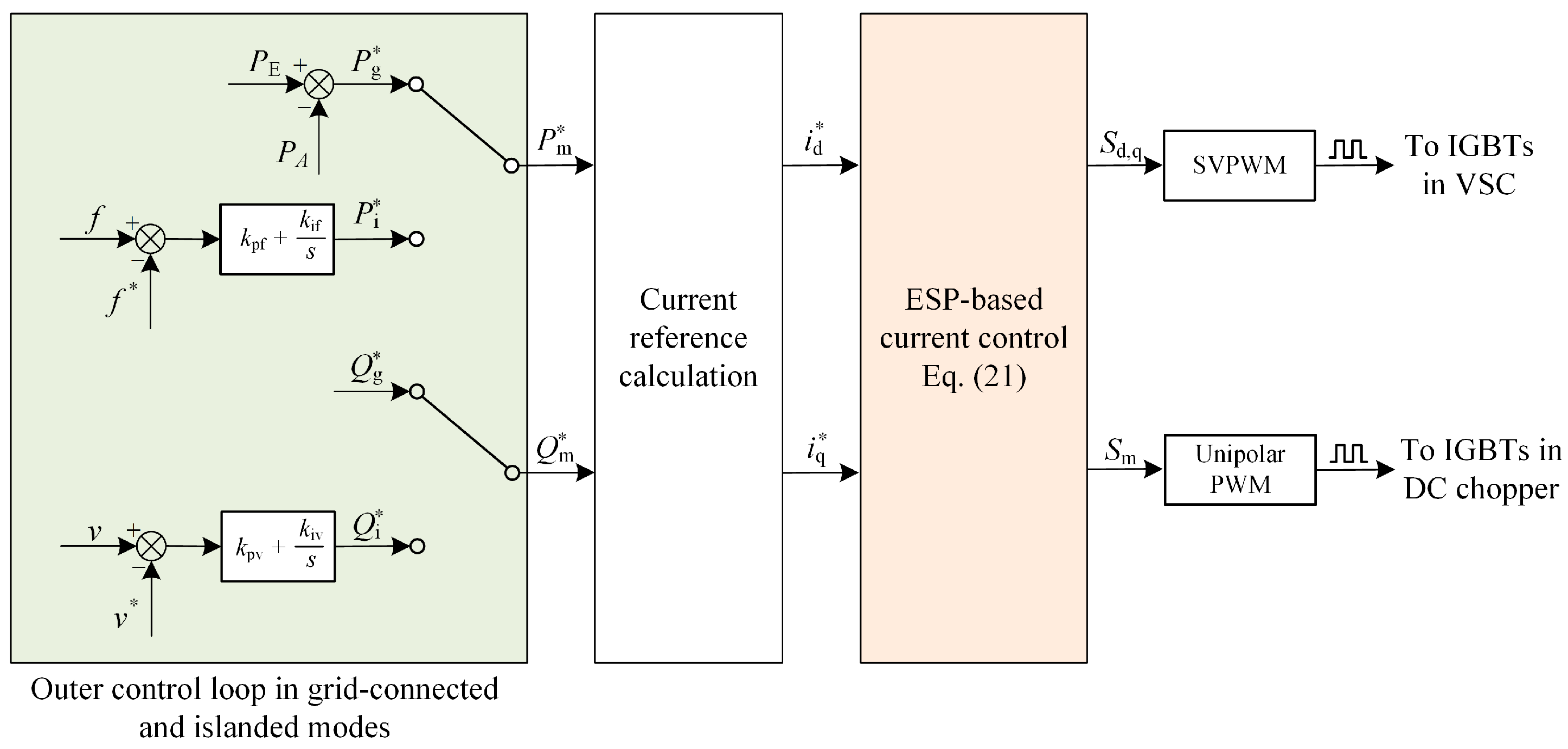
Figure 3 provides the control diagram of ESP-based SMES system. In the GC mode, the SMES real power reference is calculated by
whereas the reactive power reference is set constantly. SMES can stabilize the power fluctuation of the WG and achieve the steady power flow at the point of common coupling (PCC). The power references of SMES are obtained by using the first-order low pass filter to smooth the fluctuations in WG. In the islanded mode, an additional frequency-real power (
f-
p) PI regulator generates the real power reference of the SMES. Another outer voltage-reactive power (
v-
q) PI regulator calculates the reactive power reference of the SMES. The designed ESP-based current control strategy ensures that the SMES power can be controlled to follow the given trajectory. Meanwhile, the ESP-based strategy can stabilize the DC voltage at the given value to guarantee the normal operation of the PCS. It is noteworthy that the power tracking control is adopted without the extra power feedback in this study. Although this extra feedback can improve the precision of the power regulation, it is a tough to tune the parameters of the multi-loop PI controllers with sufficient stability. The structure of the ESP-based control system is quite different from that of the conventional PI-based control system. In the PI control system, VSC utilizes one PI controller for the power control, and the DC chopper needs another different PI regulator to maintain the DC voltage. Instead, the ESP-based method considers the SMES converters as a whole and integrates the control of VSC and DC-DC chopper together. Therefore a better overall performance it can be anticipated for the ESP-based control strategy. Finally, space vector PWM (SVPWM) technology is employed in VSC control to increase the DC voltage utilization. The unipolar PWM method is used in the DC chopper to reduce the harmonics.
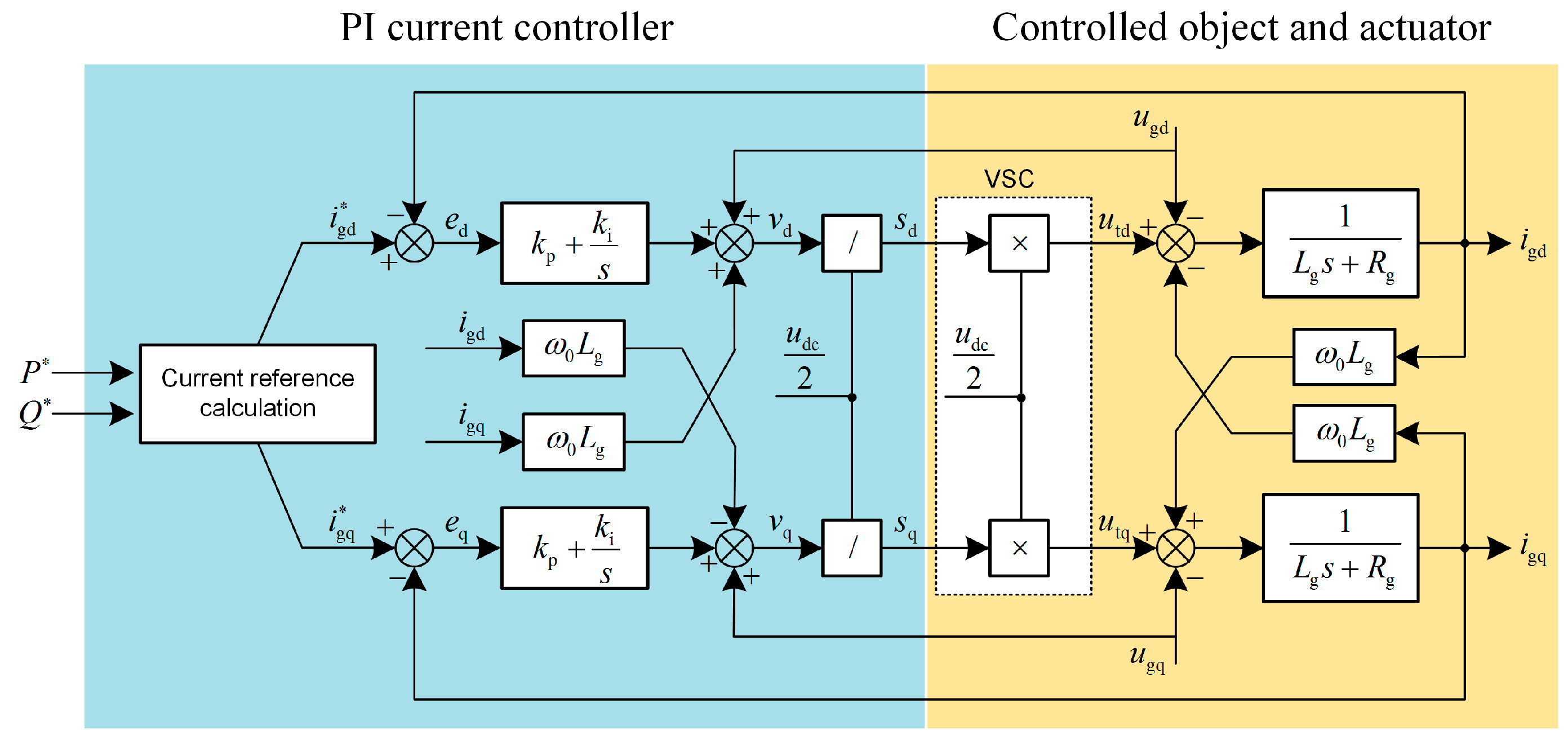
For the purpose of showing the merits of the proposed ESP-based method, the performance of the ESP-based control is compared with that of the conventional PI current control strategy in the example SMES system. In this part, the design of the conventional PI control system for comparison is briefly provided. The PI current controller for the VSC is used to regulate the output power of the SMES. The classic current feedforward decoupling PI control which is commonly employed in VSC control area is adopted in this study. The structure of the controller is depicted in
Figure 4.
As shown in
Figure 4, the grid voltage is fed forward to restrain the disturbance in the control loop. The feedforward decoupling operation eliminates the control coupling between d and q components. The detailed design strategy of this controller is presented in [
42]. The simplified control block diagram of the current loop is illustrated in
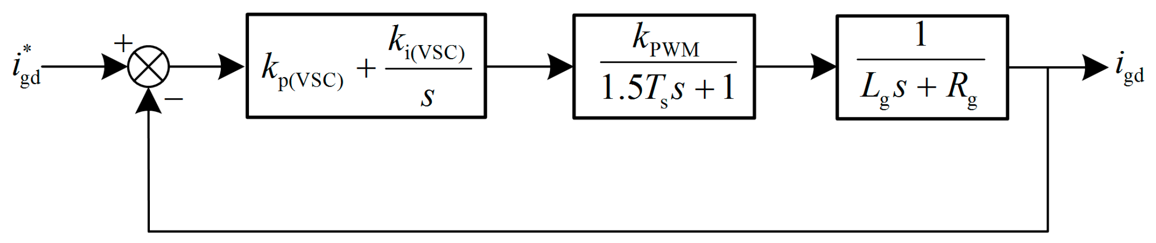
Figure 5.
In
Figure 5, the function of the PWM and sampling delay are combined into one inertia link with the time constant of 1.5
Ts. According to [
42], the adverse pole −
Rg/
Lg can be directly eliminated by the PI current controller to ensure the tracking ability of the system. By this design method, the closed-loop transfer function of the control system is a typical second-order oscillation link. Based on the optimal design method for the second-order oscillation system, the damping coefficient is determined as ξ
VSC = 0.707 to achieve the satisfactory overall performance. Accordingly, the implementation equations for PI current controller are as follows:
When the parameters of the system such as
Lg and
Rg vary, the performance of the PI control system may deteriorate because the position of the adverse pole changes and the PI controller cannot eliminate it. Meanwhile, the PI controller for the DC/DC chopper is used to control the DC voltage. The detailed design method of the PI voltage controller is proposed in [
43]. The closed-loop transfer function of the DC voltage loop is as follows:
As is shown in Equation (23), the closed-loop system is also a second-order oscillation link. In the equation, ω
n is the natural oscillation frequency;
Ti(dc) is the integral time constant in the PI voltage controller; ξ
dc is the damping ratio of the system. Considering the characteristic and demand of the DC voltage control,
Ti(dc) is chosen to be 16 ms, and ξ
dc is determined to be 2 [
43].
The additional
f-
p and
v-
q PI controllers are designed by the classic Ziegler-Nichols parameter tuning method. The primary simulation parameters are provided in
Table 1.
It should be noted that the state of charge (SOC) is a significant factor in the energy management studies which is considered for a long-term operation. However, this study focuses on the control problem in SMES which deals with the short-term operation. It is assumed that the energy managing of the SMES system has been designed appropriately. Accordingly, the SOC issue of the SMES can be neglected in our study.
4. Simulation Results and Discussion
In the simulation, the constant step-size and ode3 arithmetic is employed.
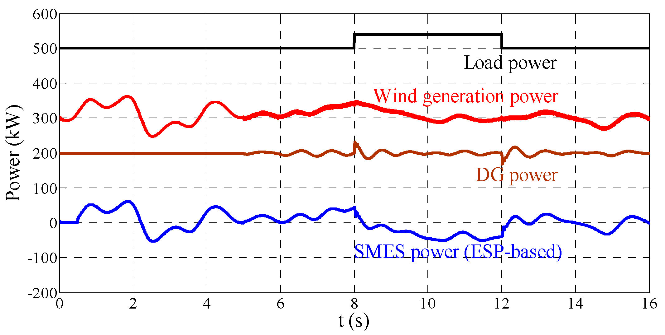
Figure 6 illustrates the power of each primary element in the example MG test system. The whole simulation period lasts 16 s. At the time point of 0.5 s, PCS converters of SMES is put into operation. At the time point of 5 s, MG transits from GC mode to the islanded mode. A load with
is switched into the MG at the time point of 8 s and disconnected at the time point of 12 s.
4.1. Simulation in the GC Mode
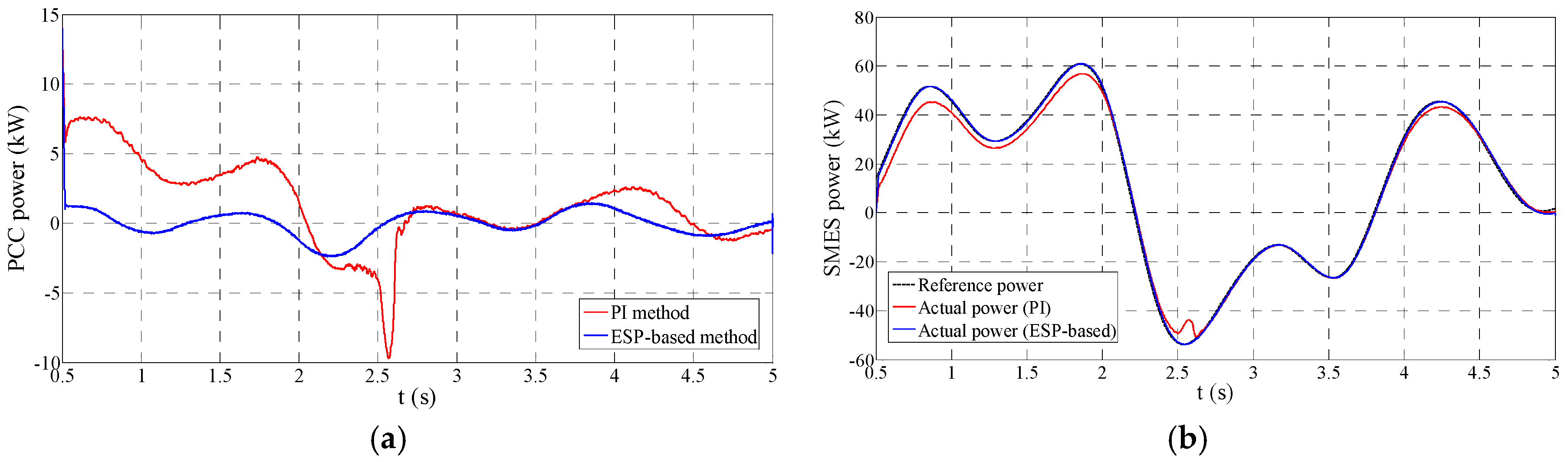
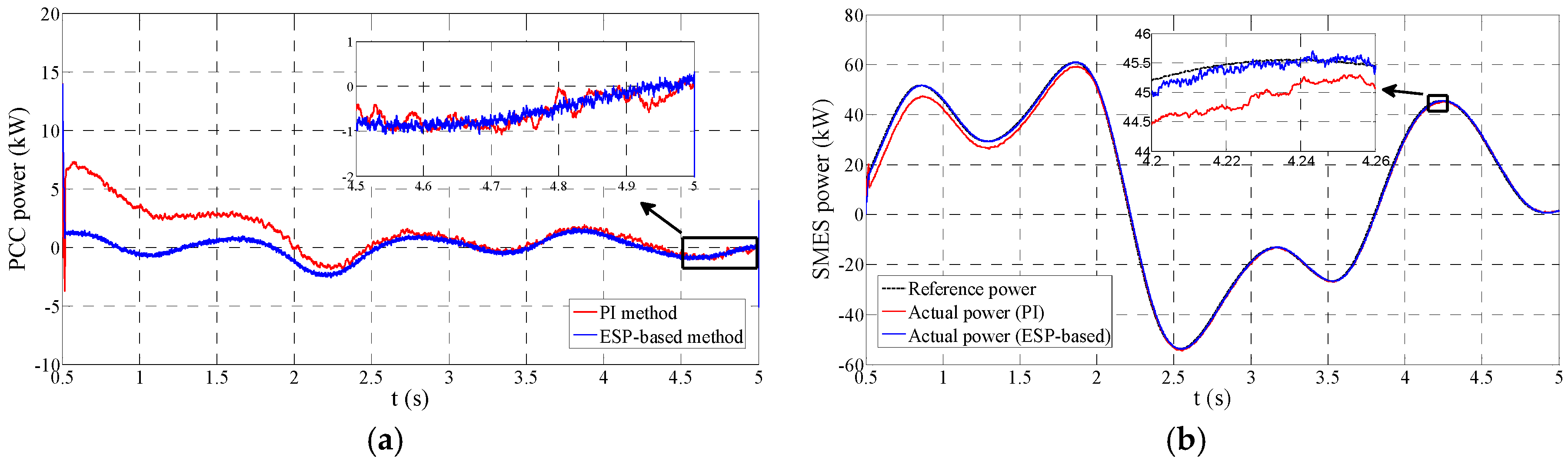
In the GC mode, SMES is employed to stabilize the WG power fluctuation, which can be seen in
Figure 7. Ideally, the constant power flow at the PCC can be achieved. In this simulation, the MG is in the GC mode before 5 s.
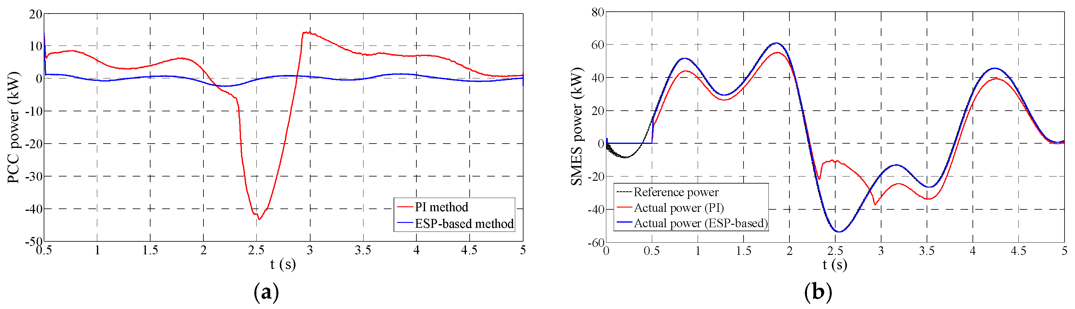
Figure 7a demonstrates the performance comparison of smoothing PCC power between PI and ESP-based control strategies under the situation of
Lg = 1 mH and
Rg = 1.1 mΩ.
Figure 7b provides a comparison of the SMES power tracking performance between these two approaches. It can be seen that both PI and ESP-based approaches can stabilize the PCC power flow and follow the power reference well. However, some visible differences between them still deserve the concern. Firstly, when the PCS of SMES is put into operation, the PI-based system has a visible 7 kW overshoot and an around 2 s regulation period as shown in
Figure 7a. Accordingly, we can notice in
Figure 7b that before 2 s the SMES power by the PI control has a distinct difference compared to the power reference and needs a regulation period to remove the error. The primary reason for this problem is that the start of the PCS is a disturbance for the control system, and the conventional PI control strategy has a relatively poor disturbance rejection performance. Conversely, the ESP-based control system practically avoids this disturbance regulation process, which can be seen in
Figure 7. Hence, the ESP-based control has stronger disturbance rejection ability in comparison to the PI method. Secondly, the steady-state performance of PI control strategy is not as satisfactory as that of the ESP-based control strategy. From the enlarged figure in
Figure 7b, it can be noticed that the ESP-based control strategy provides a smaller tracking error. Accordingly, the stabilized PCC power by the PI control strategy is not steady as that by the ESP-based control strategy. Due to the better tracking ability, the ESP-based method can reduce the low-frequency harmonic of the system and has a lower ripple in the smoothed power compared to the PI control, which can be seen in the enlarged figure of
Figure 7a.
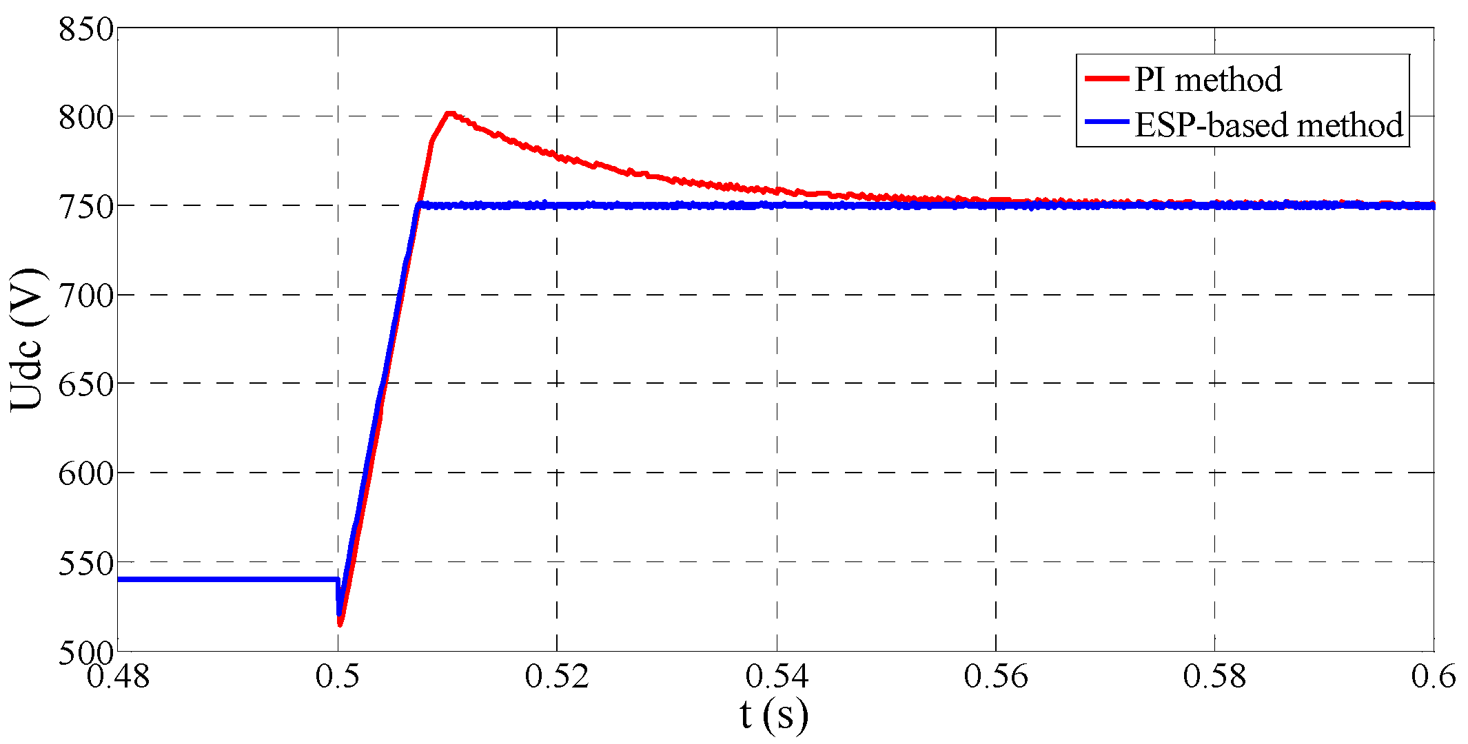
Figure 8 provides the DC voltage regulation performance. It can be found that the ESP-based control strategy has much superior dynamic performance in contrast to the PI control. More specifically, the PI control strategy has a 50 V overshoot and nearly 0.06 s regulation period. Instead, ESP-based control method turns stable in the very short time without any overshoot.
Robustness is a critical consideration for SMES control system design because the model mismatch is unavoidable in any real system. In this study, the robustness to the parameters variation of Lg and Rg are considered. The reason for this selection mainly relies on two aspects. On the one hand, the actual values of these two parameters are usually unknown and varying with the service time. Nevertheless, this kind of parameter change is often in the small range. On the other hand, these parameters could be modified deliberately to enhance the performance. This type of parameter uncertainty may be on a large scale. Hence the parameter uncertainty considered in this study is in a considerable region. If the controller can maintain the reliable performance and stability in this condition, it will greatly facilitate the design and reform of the system.
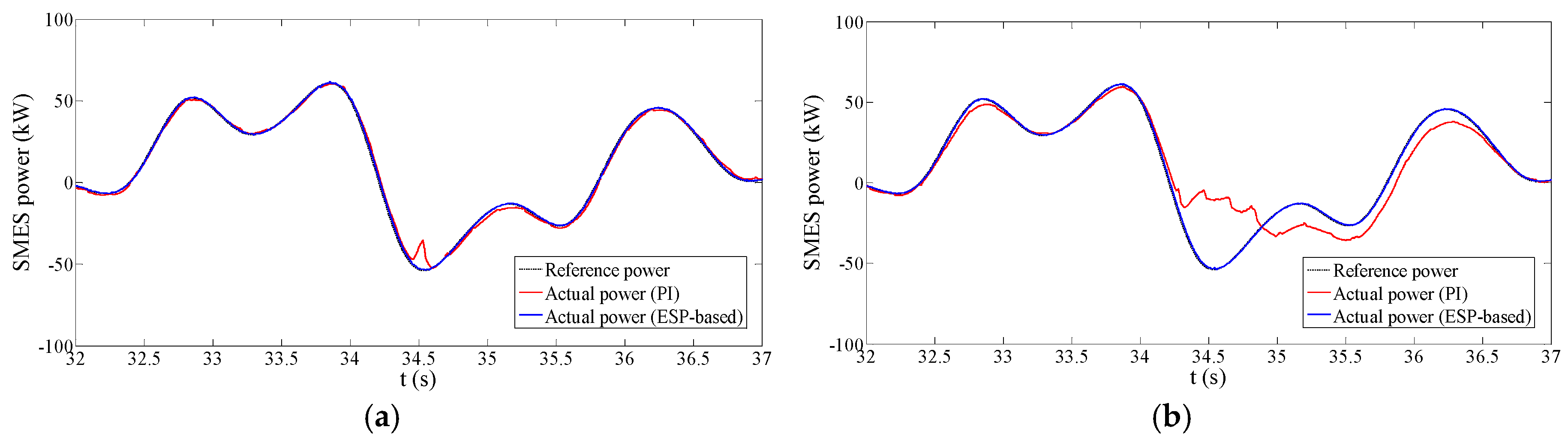
Figure 9 shows the comparison of the GC mode performance between PI and ESP-based control strategies under the condition of
Lg = 3 mH,
Rg = 0.1 Ω. while
Figure 10 provides the comparison of the situation of
Lg = 4 mH and
Rg = 0.2 Ω. It is obvious in the figures that the performance of these two approaches is quite different under the two test situations. The ESP-based control strategy keeps the good performance on both the grid power stabilizing and the reference power tracking. In contrast, the PI control strategy presents an inferior regulation performance. There is apparent reference power tracking error during most of the time. As a result, the PCC power stabilized by the PI control has a much bigger fluctuation than that by the ESP-based control. The following aspects can explain this performance difference. On the one hand, due to the enlargement of connection impedance, the tracking ability of the PCS converter decreases correspondingly. Power tracking for PCS significantly increases the difficulty and requires an outstanding tracking ability for the controller. On the other hand, PI parameters are designed based on the situation of
Lg = 1 mH and
Rg = 1.1 mΩ. Under the new circumstances, the PI control parameters are not suitable, and the controller gets a poor tracking capability. To the contrary, the ESP-based method maintains an outstanding tracking performance and presents a better robustness to parameter uncertainty. Also, we can find the performance of PI control method is especially bad near 2.5 s. Around this time, the SMES power strongly deviates from the reference power, which can be seen in
Figure 9b and
Figure 10b. Accordingly, the smoothed PCC power gets a large peak error as shown in
Figure 9a and
Figure 10a. The reason for this problem is probably that the absolute value of reference power is high and increases very steeply during this time. The PI method has serious trouble with this situation due to the insufficient tracking ability.
4.2. Simulation in the Islanded Mode
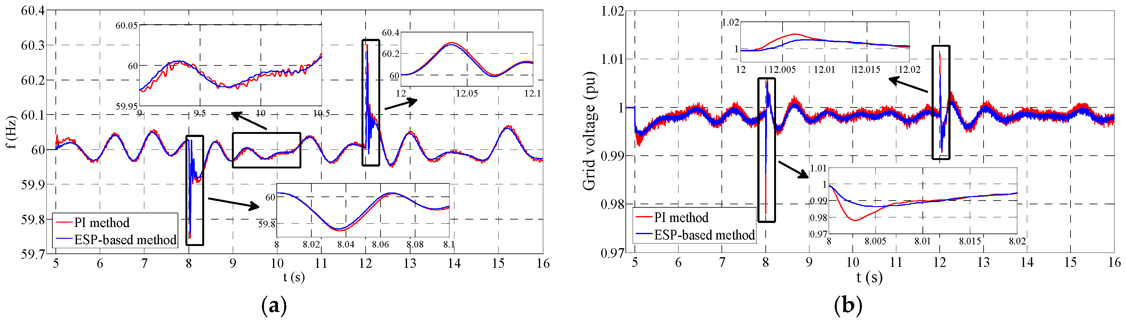
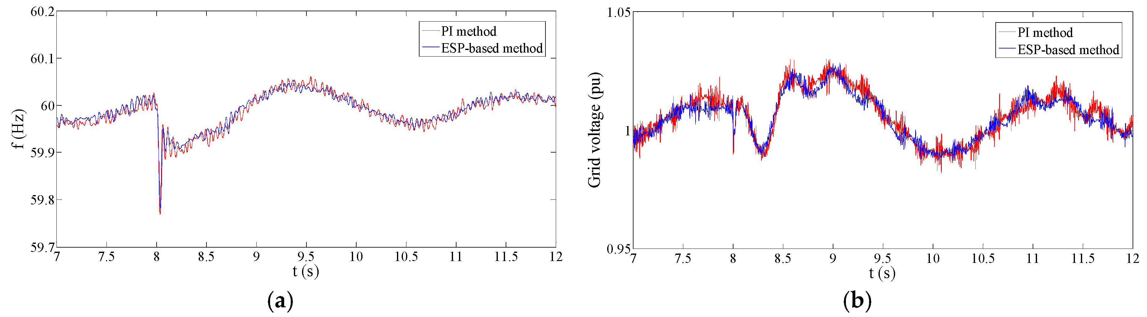
At the time point of 5 s, MG is switched to the islanded mode. The SMES system takes part in the frequency and magnitude regulation for the MG voltage.
Figure 11 provides the regulation performance under the circumstance of
Lg = 1 mH and
Rg = 1.1 mΩ.
Figure 11a,b show the comparison of the control performance in the islanded mode between PI and ESP-based control approaches, respectively. The regulation performance of the PI and ESP-based control methods is similar because the external
f-p and
v-q PI controllers are the same. Both PI and ESP-based methods can follow the reference well in this parameter situation. However, there are still some performance differences between these two approaches. On the one hand, the ESP-based control strategy presents a superior dynamic performance in comparison to the PI method. During the mode transition and load change periods, the ESP-based control has a smaller overshoot in both frequency and magnitude regulations. On the other hand, the ESP-based control method has a smaller frequency and voltage ripple.
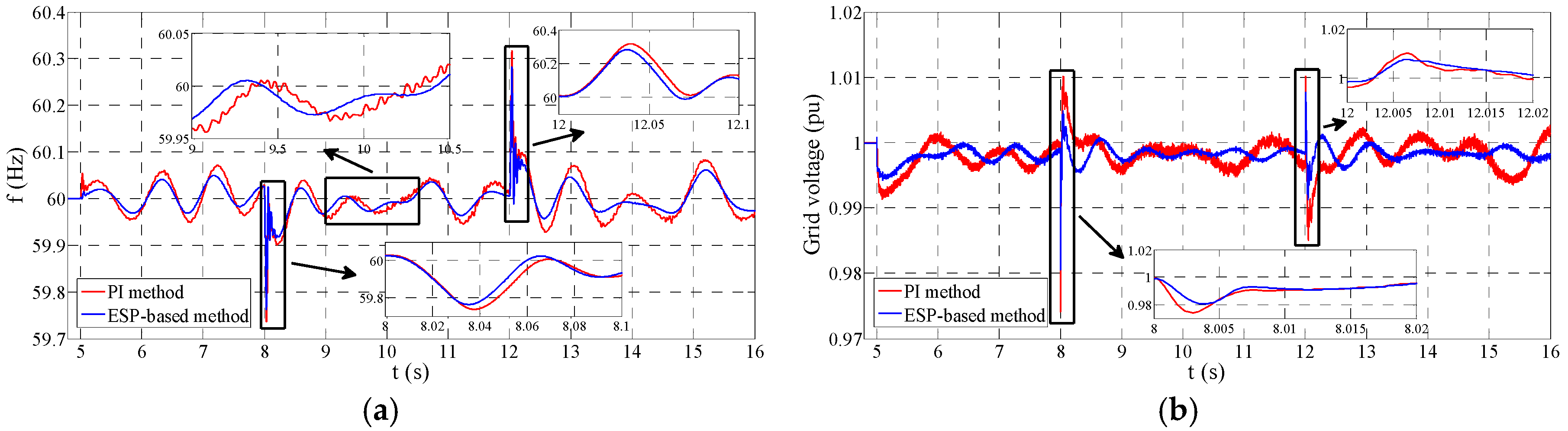
Figure 12 provides the performance comparison under the situation of
Lg = 3 mH and
Rg = 0.1 Ω. It can be found that the performance of PI and ESP-based control methods has a sharp distinction. In
Figure 12a, it is noticed that the ESP-based control provides a much smaller frequency overshoot during the islanded mode. Also, it can be seen that the frequency ripple by the ESP-based method is much lower than that by the PI method. Similarly, the voltage overshoot and ripple by the ESP-based control is also much smaller than those by the PI method. The main reason for these differences is that the tracking ability of the PI method is awful in this parameter situation as mentioned before.
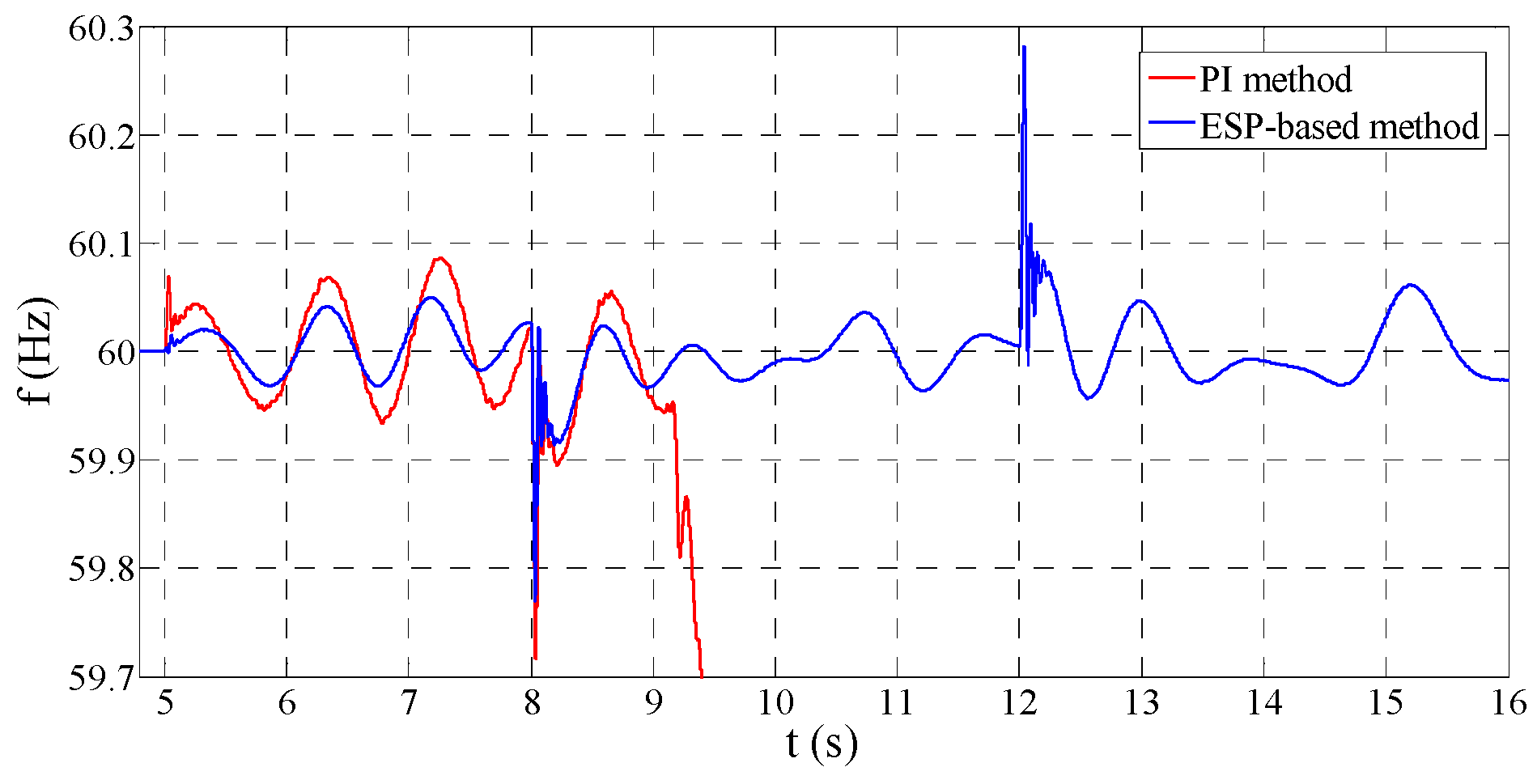
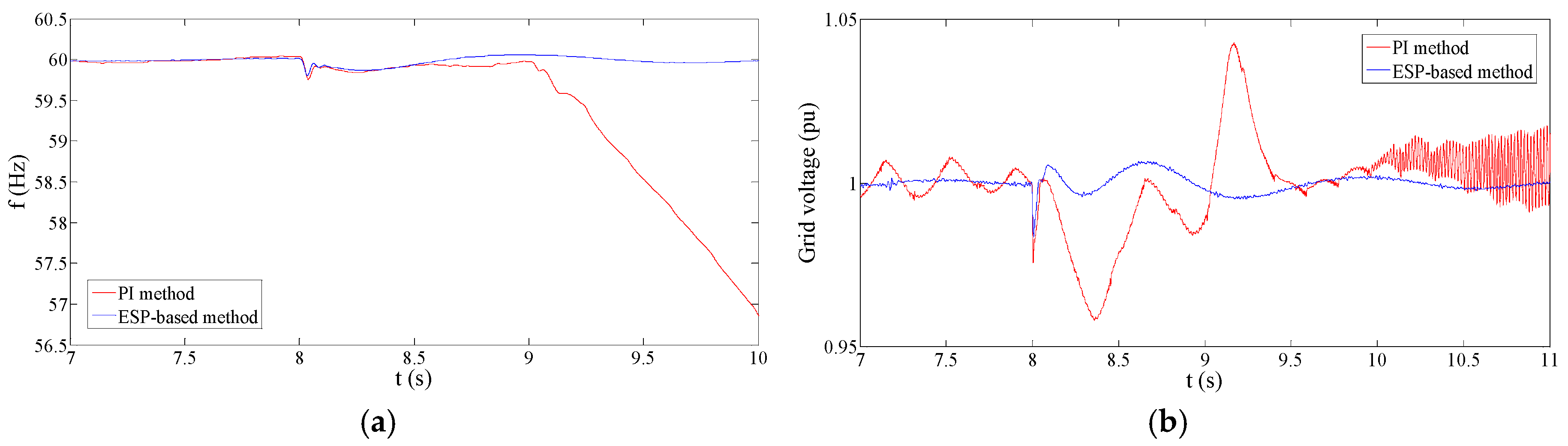
Figure 13 shows the frequency regulation performance under the situation of
Lg = 4 mH and
Rg = 0.2 Ω. It can be seen that the PI method becomes unstable, whereas the ESP-based method maintains the proper performance in this situation. The poor tracking ability can explain this stability problem for the PI method. When the power reference is large and fast-changing, the frequency regulation of the PI control method gets unstable due to the insufficient tracking capability under this parameter situation. It is concluded that the ESP-based method has a larger stability region than PI method under the situation of parameter uncertainty.
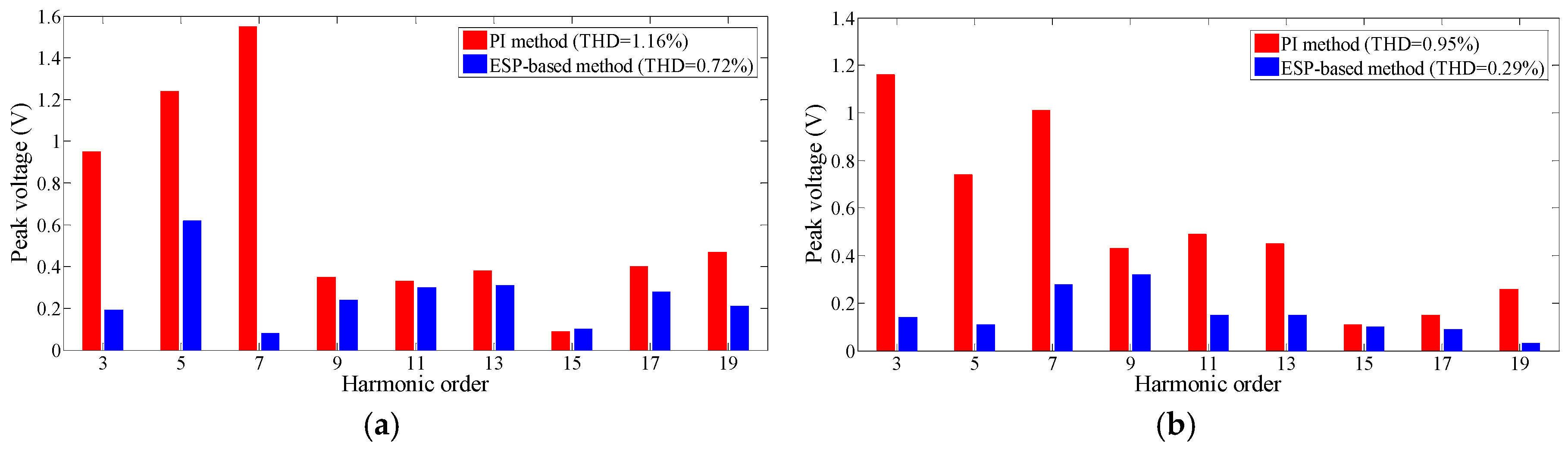
Figure 14 compares the harmonic of the grid voltage controlled by the PI and ESP-based control methods.
The results show that the typical harmonic in the grid voltage by the ESP-based method is smaller than that by the PI method due to the superior tracking ability. When the system parameters change, the harmonic performance of the ESP-based method is much better than that of the PI control.
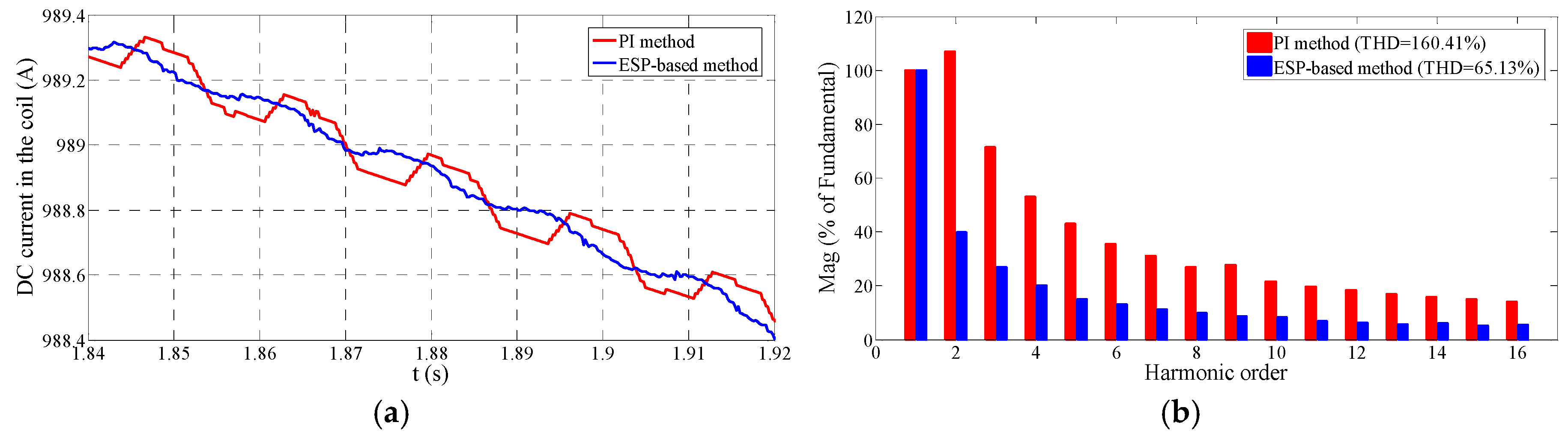
4.3. The Harmonic Analysis of the Superconducting Coil Current
The eddy current loss in the SMES system is an important consideration, for it greatly influences the efficiency of the system. Meanwhile, the eddy current loss has a significant relationship with the harmonic of the DC current in the superconducting coil, especially the low-order harmonic (2nd and 3rd) [
44]. In this part, the comparison of the DC current harmonic between PI and ESP-based methods is provided to estimate the eddy current loss conditions.
It can be easily found in
Figure 15a that the DC current by the ESP-based method is much more sinusoidal than that by the PI method. We also provide the low-order harmonic analysis in
Figure 15b. The harmonic of the DC current is substantially reduced by the ESP-based method due to the outstanding tracking ability. Therefore, the ESP-based method can be estimated to achieve the eddy current loss reduction and the system efficiency improvement.
4.4. Discussion
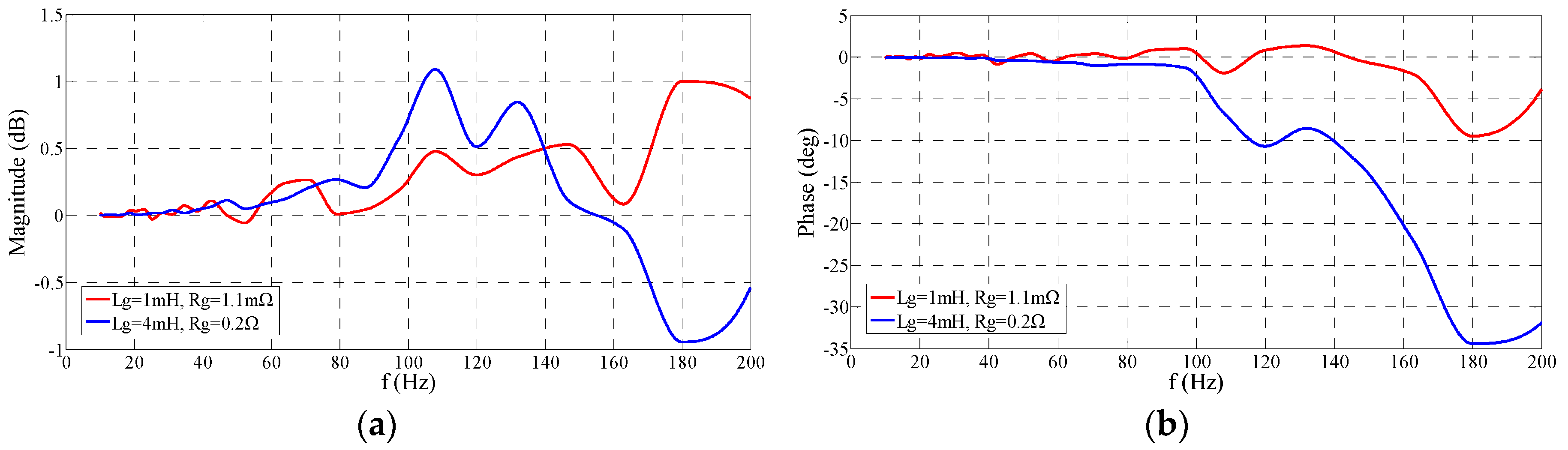
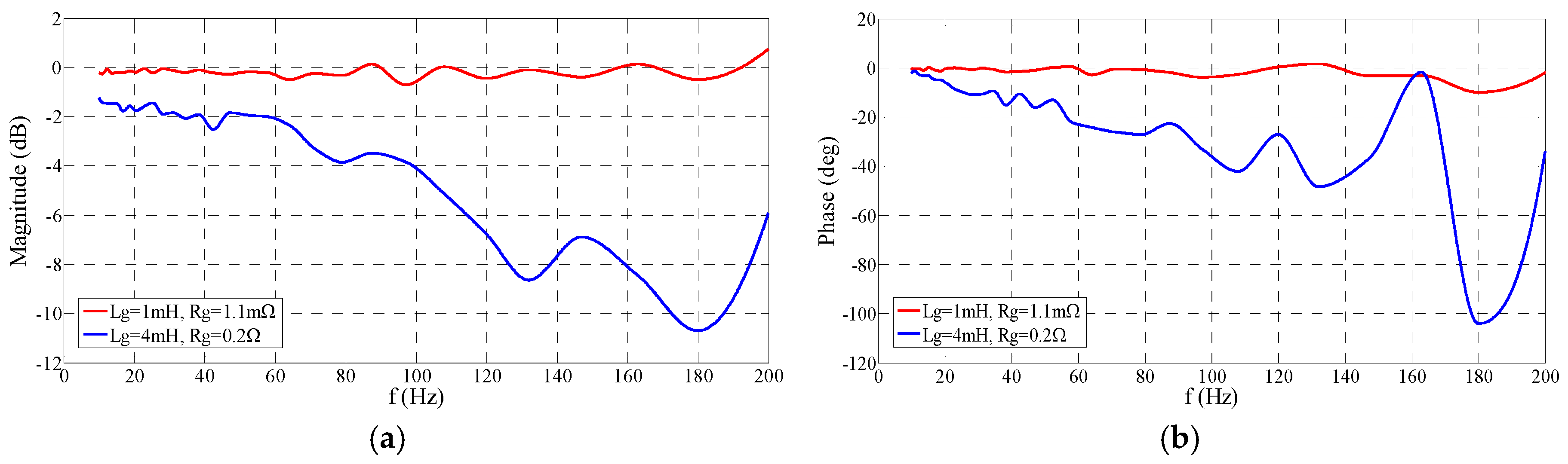
In this part, some discussions based on the simulation results are provided. Firstly, in order to well explain the difference in simulation results between PI and ESP-based method, the frequency response of the current control loops are tested by the control design toolbox in Matlab. The amplitude of the input test current is 10 A, and the frequency variation range of the input is from 10 Hz to 200 Hz.
Figure 16 and
Figure 17 provide the frequency response results of the PI and ESP-based current controllers under two different parameter situations. Under the expected parameters, both the PI and ESP-based control present a satisfactory frequency response, which proves the correctness of the controller design in this study. The magnitude gain range is within ±1 dB, and the phase shift is within ±10 degree. Both PI and ESP-based control can achieve good tracking performance under this situation. When the parameters change, the magnitude gain of the ESP-based control is still in the region of ±1 dB. Nevertheless, the maximum phase shift increases to be −35 degree which is still acceptable due to the enlargement of the output impedance of the converter. In contrast, both the magnitude and phase characteristics of the PI control deteriorate seriously under this situation. From the frequency response analysis, it can be concluded that the ESP-based control can remain the good tracking capability when parameters change, while the parameters affect the tracking ability of the PI control significantly. This conclusion also can well explain the previous simulation results.
Secondly, in order to verify the model adopted to design the ESP-based controller, a brief sensitivity analysis [
45] is provided in this part. The sensitivity analysis factor (SAF) which is defined in Equation (24) is introduced to evaluate the sensitivity of the controller to system parameters:
In Equation (24), represents the change rate of evaluating indicator; means the change ratio of the uncertain system parameter. The positive/negative signs of the SAF reveal that the evaluating indicator changes with uncertain system parameter at the same/opposite direction. In the GC mode, SMES is used to smooth the WG power. Hence, the peak-to-peak power (Pp-p) of the PCC power is adopted as the evaluating indicator.
The magnitude of
Pp-p can evaluate the steady degree and the ripple level of the smoothed power.
Table 2 provides SAF performance when the system parameters change. Considering that some parameters in the power system are prone to change, the parameter variations in the sensitivity analysis consider not only the structural parameters of SMES but also the related parameters of power grid. It can be found that the performance is not sensitive to the most of the parameter variation, which proves the effectiveness of the adopted model and the designed ESP-based controller. The performance is a little sensitive to the grid voltage and the WG power fluctuation. However,
Pp-p is still small enough to guarantee the good performance.
In the islanded mode, the frequency overshoot (△
f =
f − 60) when the load changes (at the time point of 8 s) is employed to be the evaluation indicator in the sensitivity analysis. It can be seen from
Table 3 that the most of the parameters have little effect on the transient performance of the controller.
The load change influences the transient performance of the system to some extent. If the tolerance limit of △f is determined as ±0.5 Hz, the permitted load change region is approximately ±140 kW which is obtained by the simulation test.
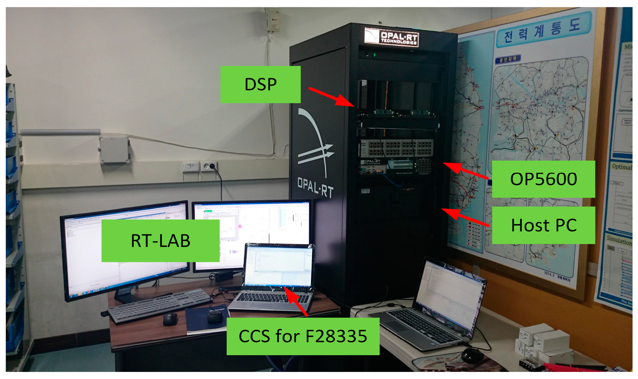
5. Experimental Verification
In order to further verify the feasibilities of the proposed control method, the real-time simulation based on the hardware-in-the-loop simulation (HILS) using OP5600 and OP8665 (OPAL-RT Technologies, Montreal, QC, Canada) is implemented. The HILS system used for the test of proposed control method is depicted in
Figure 18.
As shown in
Figure 18, the HILS system can simulate the complex MG and the converter of SMES by the programming of the software RT-LAB (Version 11, OPAL-RT Technologies, Montreal, QC, Canada). The OP8665 including the digital signal processor (DSP) TMS320F28335 implements the proposed control method by sampling the analog signal from the OP5600 and generates the PWM commands for the converter of SMES. All of the parameters in the experiment are the same with those in the previous simulation to facilitate the comparison. Nevertheless, the WG power is extended periodically every 16 s in contrast to
Figure 6.
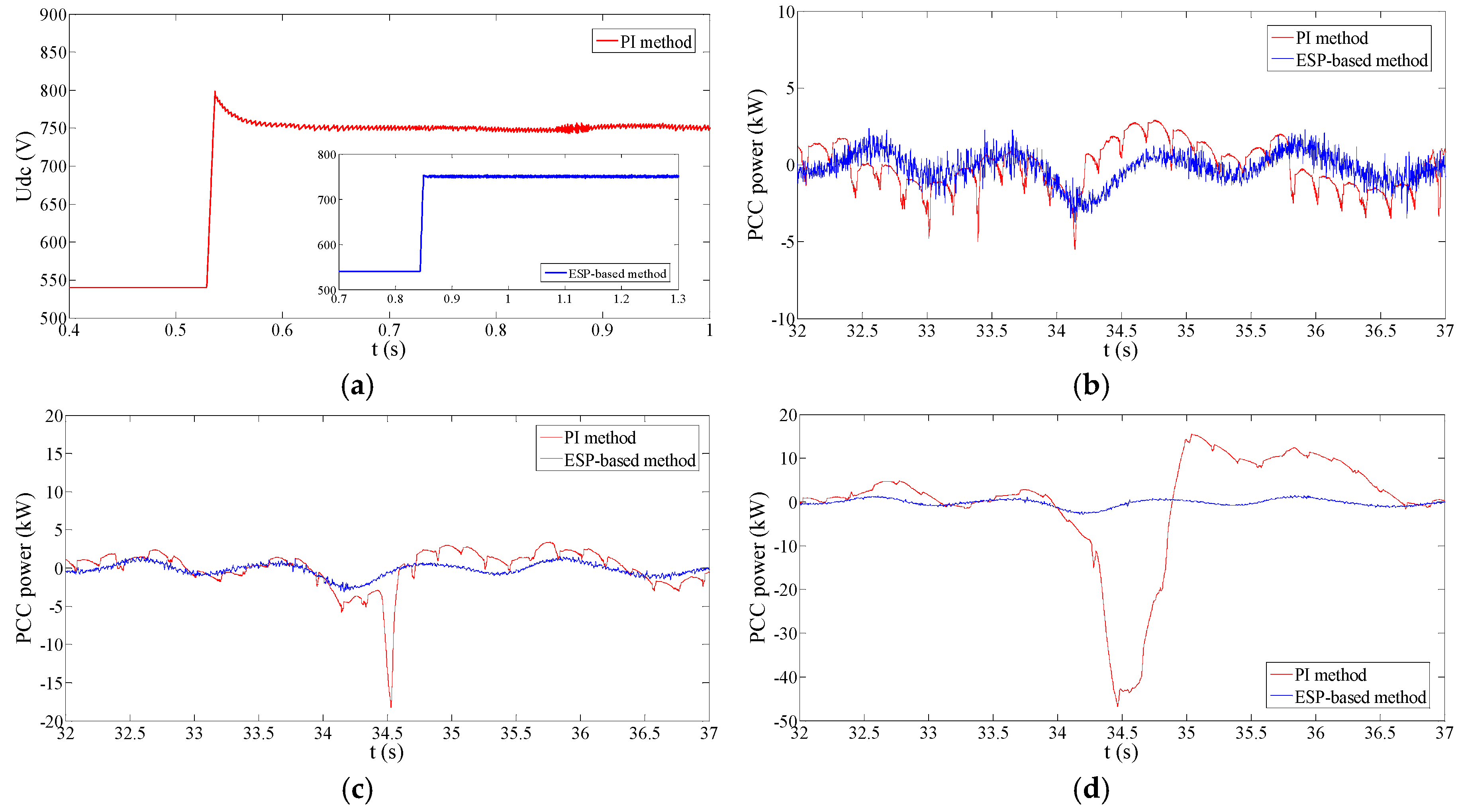
Figure 19a compares the DC voltage performance between the PI and ESP-based methods. The DC voltage by the ESP-based method has a much better transient performance without any overshoot than PI control.
Figure 19b provides the comparison of the WG power smoothing performance under the expected parameter. The performance of PI and ESP-based control methods are both satisfactory under this situation. It can be noticed that the switching ripple of ESP-based control mainly lies in the high-frequency region, which is easily absorbed by the additional LC or LCL filter.
Figure 19c,d demonstrate the performance comparison under the situation of the parameter change.
Figure 20a,b provide the SMES power tracking performance under these two conditions. The experimental results are quite similar with the previous simulation results. Both of the power smoothing and the power tracking performance are poor by the PI control method when parameters change. In contrast, the performance of ESP-based control method is still satisfactory under the situation of the parameter variation. The reasons for the performance difference have been analyzed in
Section 4.
Figure 21 provides the frequency and voltage regulation performance in the islanded mode without the parameter variation. It can be found that under the expected parameter situation the performance of the PI and ESP-based methods are quite similar. The reason is that their outer
f-
p or
v-
q controllers are the same, and in this parameter situation, both PI and ESP-based methods have the good tracking ability.
Figure 22 shows the regulation performance when
Lg = 4 mH and
Rg = 0.2 Ω. Under this situation, the PI-based control system becomes unstable due to the poor tracking capability. To the contrary, the ESP-based method remains the good regulation performance when parameters change.
6. Conclusions
In this study, an ESP-based control strategy, which can integrate the VSC and DC chopper regulation together, has been proposed for the robustness improvement of SMES systems. A stepwise ESP-based design strategy in the SMES system has been presented, which consists of four steps: building the mathematical model, establishing the balance positions, energy shaping, and introducing the integrators. The designed ESP-based regulator is easily realized in the programming. Experimental verification by using the HILS system with DSP was performed in this study to show the validity of the proposed controller.
A comparison between the ESP-based and PI strategies is presented to show the merits of the proposed ESP-based control. The parameters of the connection impedance of the PCS converter were changed to test the robustness of the controllers. Both the PI and ESP-based control methods could follow the power reference well under the expected parameter situation. Nevertheless, ESP-based control avoids the disturbance rejection process and achieves a flatter PCC power flow under the GC mode. Moreover, the ESP-based control provides a smaller overshoot and ripple in contrast to the PI control method under the islanded mode. When the system parameters change, the ESP-based control method could achieve a much superior performance than PI control. In particular, when the reference power was high in value and varied steeply simultaneously, the SMES power controlled by the PI controller would deviate from the reference due to the insufficient tracking ability. This problem also caused a weak stability region for the PI method when parameters vary. It can be concluded from the simulation results that the ESP-based control strategy has a superior robustness to the parameter variation in comparison with the conventional PI control strategy. Besides, the ESP-based method significantly reduced the harmonic of DC current compared with the PI method, which results in the reduction of eddy current losses compared to the PI control method.
The SMES with the designed ESP-based control method might provide better overall performance compared with the conventional PI-based SMES. On the one hand, the good robustness of ESP-based SMES could maintain the satisfactory performance even when converter parameters change, and this could avoid the redesign process in some cases. On the other hand, ESP-based SMES can provide better dynamic property for improving the transient performance of the power system.


