
Active Vibration Control of Swash Plate-Type Axial Piston Machines with Two-Weight Notch Least Mean Square/Filtered-x Least Mean Square (LMS/FxLMS) Filters

Maha Fluid Power Research Center, Purdue University, Lafayette, IN 47905, USA
*
Author to whom correspondence should be addressed.
Energies 2017, 10(5), 645; https://doi.org/10.3390/en10050645
Submission received: 30 March 2017
/
Revised: 21 April 2017
/
Accepted: 2 May 2017
/
Published: 6 May 2017
(This article belongs to the Special Issue Energy Efficiency and Controllability of Fluid Power Systems)
Abstract
:In this paper, swash plate active vibration control techniques were investigated utilizing the weight-limited multi-frequency two-weight notch Least Mean Square (LMS) filter with unit delay compensation and multi-frequency two-weight notch Filtered-x Least Mean Sqaure (FxLMS) filter with offline modeling to achieve adjustable swash plate vibration reduction at the desired frequency. Simulation studies of the high fidelity pump control system model including realistic swash plate moments are presented to demonstrate the feasibility of the swash plate active vibration control. A 75-c/rev swash plate type axial piston pump was modified to implement a high bandwidth pump control system which is required for canceling the swash plate vibration. High speed real-time controllers were proposed and realized using an National Instrument LabVIEW Field Programmable Gate Array (FPGA). Vibration measurements using a tri-axial swash plate acceleration sensor were conducted to show the influence and effectiveness of the proposed swash plate active vibration control system and algorithms.
1. Introduction
Positive displacement machines are used in many industrial applications such as construction machines, airplanes, agriculture, hydraulic hybrid vehicles, robots, etc. Axial piston machines are popular among various types of positive displacement machines due to their advantages of high pressure level, high efficiency, controllability, and compactness [1]. However, the principle of utilizing a finite number of displacement chambers/pistons in swash plate type axial piston pumps generates oscillating forces in the rotating group. These oscillation forces and resulting moments introduce vibrations to all pump parts, especially to the swash plate and the pump housing. Structural vibrations generate noise and decrease pump reliability by inducing fatigue wear [2,3,4,5]. Thus, it is desirable to introduce technologies which can help to damp these vibrations. Few researchers have studied passive/active vibration control techniques utilizing the pump control system. A passive swash plate vibration control technique was investigated by connecting displacement chamber and the swash plate control cylinders [6]. Active swash plate vibration control techniques relying on human tuning of the phase and amplitude of sinusoidal cancellation signal were investigated for both even and odd pistons pumps [7,8]. Recently, the author demonstrated the feasibility of active vibration control based on the adaptive Least Mean Squares (LMS) filter [9]. In this paper, swash plate active vibration control is investigated using weight-limited Two-weight Notch LMS (TNLMS) and Two-weight Notch Filtered-x LMS (TNFxLMS) filters to achieve adjustable swash plate vibration reduction at desired frequency.
2. High Bandwidth Pump Control System
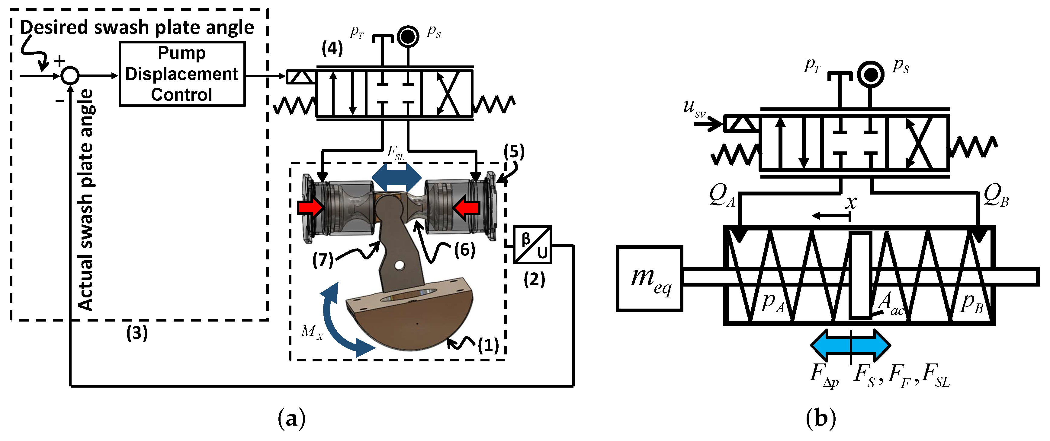
The idea of swash plate active vibration control is to compensate swash plate vibration by creating destructive interference force using the pump control system [10]. High frequency of the swash plate vibration is the main challenge for the swash plate active vibration control. The fundamental frequency of swash plate moment is piston number (z) times the fundamental frequency of rotational speed. A high bandwidth pump control system structure is proposed utilizing a high bandwidth servovalve together with an electronic swash plate angle sensor and a high-speed controller as shown in Figure 1a.
The electronic swash plate angle sensor (2) measures the angular position of the swash plate (1). The high speed controller (3) sends control signals to the servovalve (4) which regulates fluid flow to either side of the control cylinder (5) based on the swash plate angle sensor feedback signal. The translational movement of control actuator (6) is converted to a swash plate rotational motion by the linkage system connected to the swash plate lever arm (7).
Pump Control System Modelling
Figure 1b shows a simplified diagram of the pump displacement control system including a servovalve, a swash plate control actuator, and an equivalent mass. The pump control system consists of a hydraulic part and a mechanical part. The hydraulic part consists of a servovalve, which distributes fluid to either side of control cylinders, and a control cylinder, which moves the swash plate through a linkage system according to the fluid flow entering and leaving. The mechanical part comprises the swash plate and linkage systems which convert the control actuator linear motion to the swash plate rotational motion. As a simplification, all masses of the mechanical system can be lumped together as a single equivalent mass (). This simplified pump control system model can be described by combining the force balance equation (Equation (1)), pressure build-up equation (Equation (6)), servovalve flow rate (Equation (7)), and servovalve dynamics (Equation (8)).
3. Swash Plate Active Vibration Controller Design
3.1. LMS Algorithm
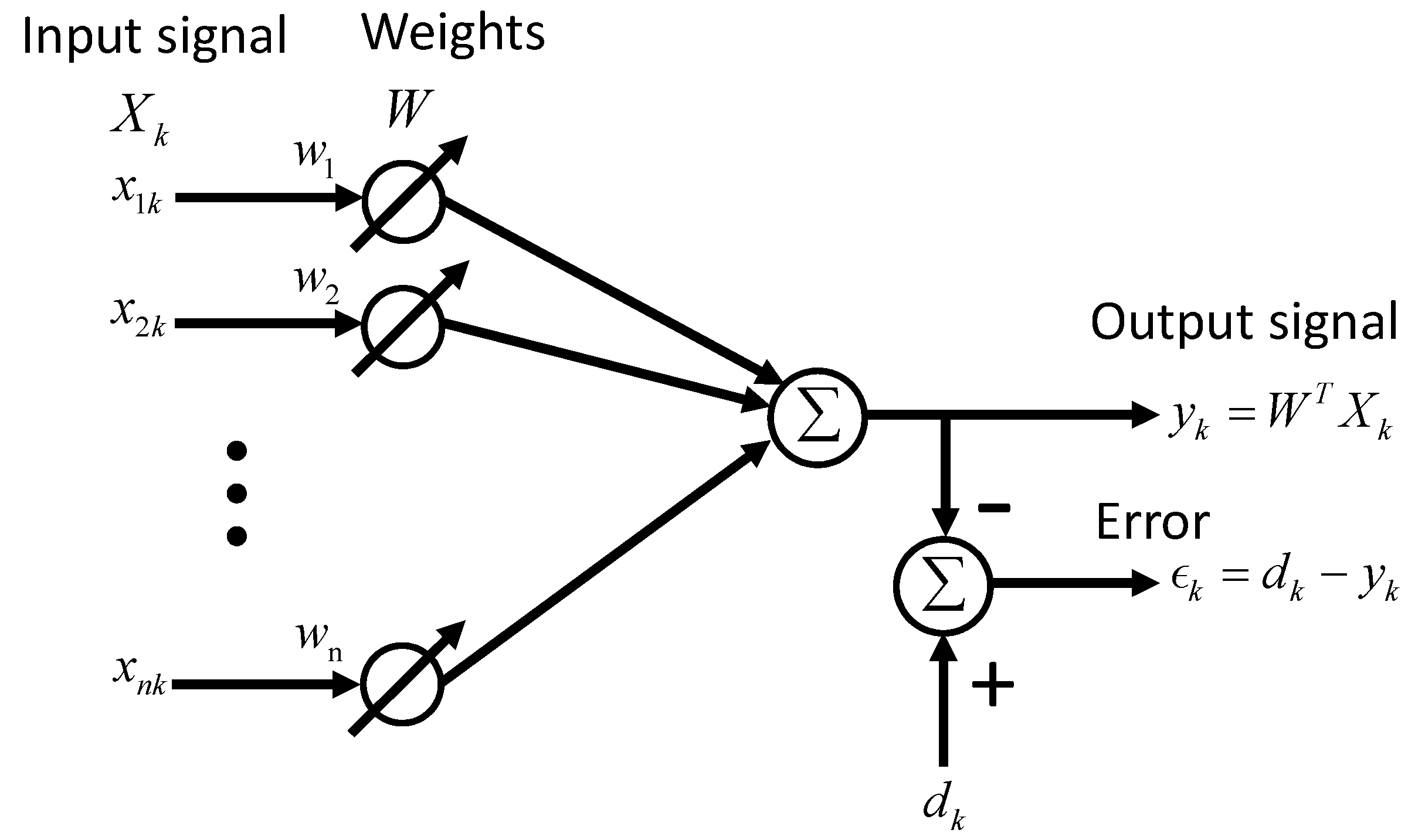
Adaptive filters and LMS algorithms are explained in this section based on the approach of Widrow and Walach [12]. Figure 2 shows the structure of an adaptive finite impulse response (FIR) filter. Where represents an input signal vector, W represents an adaptive filter weight vector, n is an adaptive filter length, and y represents an adaptive filter output signal. The error signal of an adaptive filter is defined as a difference between the desired response and the filter output signal as shown in Equation (10). The square of error can be calculated as shown in Equation (11). The mean square error () is defined as shown in Equation (12).
3.2. Two-Weight Notch LMS Filter
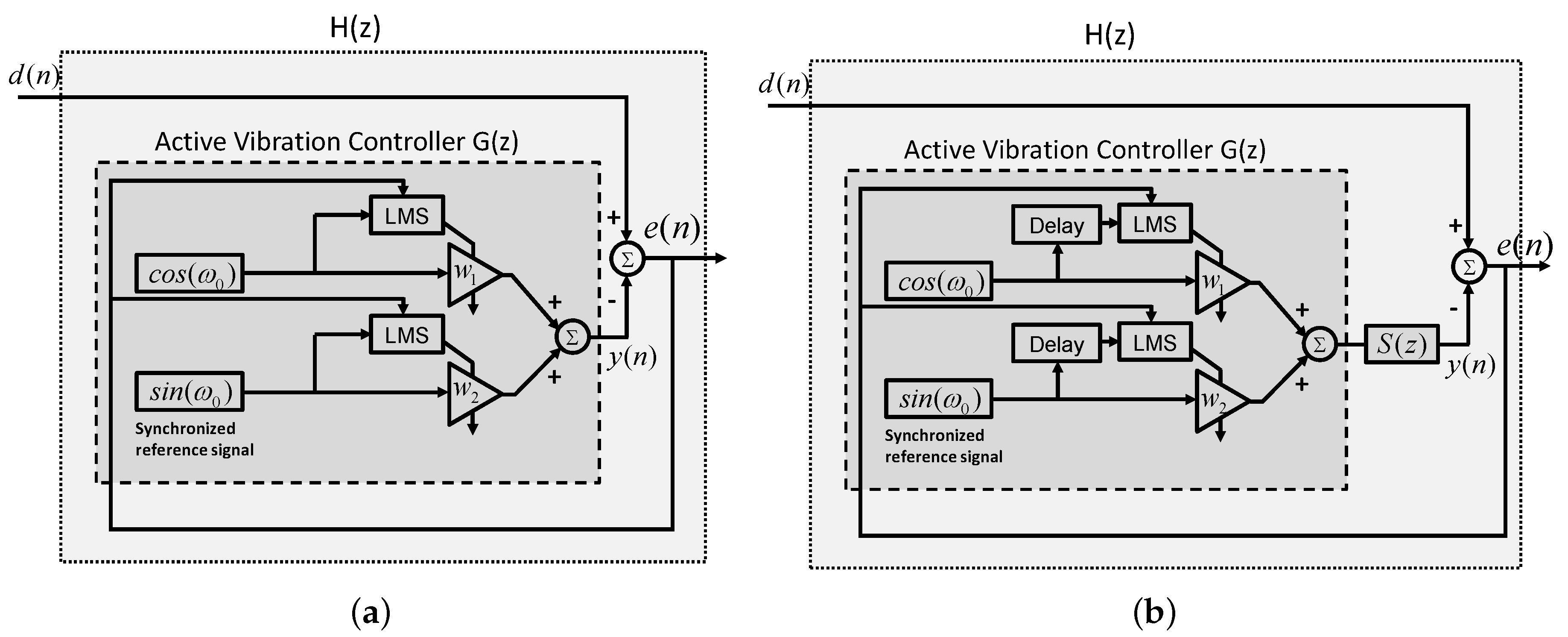
The swash plate vibration consists of multiple narrowband vibrations whose frequencies are integer multiples of the swash plate moment fundamental frequency which is a piston number times the rotational frequency. Thus, narrow band LMS filters and a rotational speed sensor can be an effective combination for the swash plate active vibration controller. The benefit of using a rotational speed sensor is the ability to generate reference signals without unfavorable feedback from the vibration cancelling signal [13]. Figure 3a shows a block diagram of the feed-forward single frequency Two-weight Notch LMS (TNLMS) filter. This feedforward controller consists of two synchronized reference signal generators, two LMS algorithms, and two weights. The method uses a weighted sum of the cosine signal and the sine signal to construct an adaptive notch filter. Widrow et al. showed that the adaptive LMS filter, can be modeled as an equivalent linear transfer function with a sinusoidal reference input as shown in Equation (17) [14].
3.3. Two-Weight Notch LMS Filter with Delay Unit Compensation
The main issue when implementing active vibration control is the generation of exactly opposite phase vibration canceling signals, which cannot be obtained without compensating system dynamics and sensor delays. Filtered-x Least Mean Square (FxLMS) algorithms, which include delay-compensating filters before the LMS algorithm, have been used to compensate this phase difference between vibrations and control signals. The TNLMS filter with delay unit compensation is a simple form of a FxLMS filter which has delay units before the LMS algorithm and adjusts phase lags of the system transfer function () as shown in Figure 3b. With the delay unit compensation, the filter output can be calculated as Equation (20).
The weights are updated by the LMS algorithm with delayed reference signals as shown in Equation (21) [13].
3.4. Two-Weight Notch FxLMS Filter with Offline Modelling
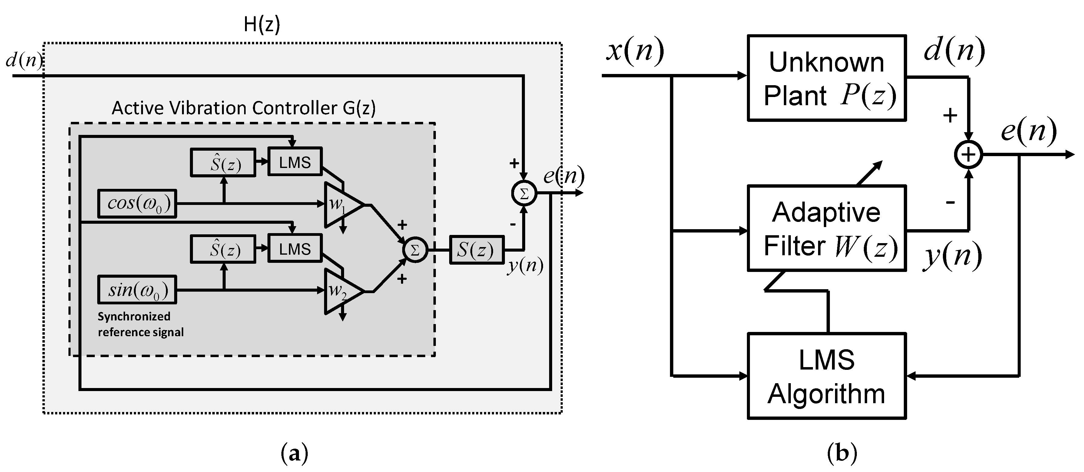
A Two-weight Notch FxLMS (TNFxLMS) filter can be constructed by using a system transfer function estimation () instead of the delay unit used in Figure 3b. Figure 4a shows a TNFxLMS filter. With the system transfer function estimation (), LMS filter weights are updated by the estimated system transfer function outputs ( and ) instead of reference signals ( and ) as shown in Equation (22).
The stability condition of FxLMS filters with system transfer function estimations is explained in detail as below [13,16]. Assume the disturbance signal () and the system transfer function estimation () as Equation (23). The error signal can be expressed as Equation (24),
where and are an amplitude and a phase of at frequency . Setting the error equation to zero, the required amplitude and phase of can be calculated as Equation (25),
The open loop transfer function which represents the relationship between the error signal and the output signal was presented by Elliott and Nelson [16] as Equation (26),
where and are the phase and the amplitude of . From Equation (26), the transfer function between the disturbance signal and the error signal can be calculated as Equation (27),
where . The effect of system transfer function estimation accuracy was investigated by Widrow and Stearns [17] as Equation (28),
where . The poles of Equation (28) can be calculated as below equation which are complex conjugate poles with radius .
Since , , and are all positive values, is also a positive value. The pole radius is larger than unity only when is negative. Therefore the stability condition can be written as Equation (30).
Lastly, slower adaptation speed of the FxLMS algorithm presented with lower estimation accuracy [18].
3.5. Swash Plate Active Vibration Controller
The swash plate active vibration controller consists of a feedback controller part and a feedforward controller part as shown in Figure 5 and Figure 6. The feedback controller is a pump displacement controller which manages the closed loop displacement control using an electronic swash plate angle sensor. A Proportional-Integral-Derivative (PID) controller can be used for the pump displacement control. The feedforward controller is a vibration controller which utilizes a rotational speed and a swash plate acceleration to generate anti-phase vibration cancelling signals which make destructive interference forces.
Two different vibration controllers are developed for the swash plate active vibration control. One is the multi-frequency two-weight notch least means square (MTNLMS) filters with delay unit compensation as shown in Figure 5. The other controller is the multi-frequency two-weight notch filtered-X least mean squares (MTNFxLMS) filter with offline modeling algorithm as shown in Figure 6 which has estimated plant model instead of the delay unit compensation. The swash plate active vibration control procedure can be explained as follows. While the displacement controller maintains the desired swash plate angle utilizing an electronic swash plate angle sensor feedback, pump rotational speed is measured and converted to harmonic frequencies of the swash plate vibration which will be used to generate cosine and sine reference signals. The reference signals proceed to the LMS algorithm through delay units or estimated model to compensate pump control system dynamics and sensor delays. The LMS algorithm updates adaptive filter weights to minimize the swash plate acceleration error signal.
Also, the estimated pump model can be determined by offline modeling techniques or online modeling techniques [13]. Figure 4b describes the off-line plant modeling technique using an adaptive LMS filter. Assuming the unknown plant is a time-invariant system, the plant can be modeled using an length L FIR filter [13]. Utilizing an input signal and an error signal of the unknown plant, the LMS algorithm updates adaptive filter weights to create a filter output which minimizes the error signal . As a result, the adaptive filter replicates the unknown plant response.
3.6. Swash Plate Active Vibration Control Simulation
Feasibility of the proposed controller was investigated utilizing Matlab Simulink (2016a) simulations prior to field-programmable gate array (FPGA) implementation and experimental study. A linearized pump model and the measured swash plate acceleration from a 75 c/rev swash plate type axial piston pump were used for this simulation study. The measured swash plate acceleration is added to the simulation. The swash plate acceleration is measured from an acceleration sensor attached to the swash plate side. The measurement operating conditions were 800 rpm rotational speed, 7° swash plate angle, and 75 bar delivery pressure. A 5 ms signal delay was added to the linear model acceleration signal output to replicate delays of a real pump control system. Added delays and pump control system phase lags are compensated by delay unit compensations of the active vibration controller.
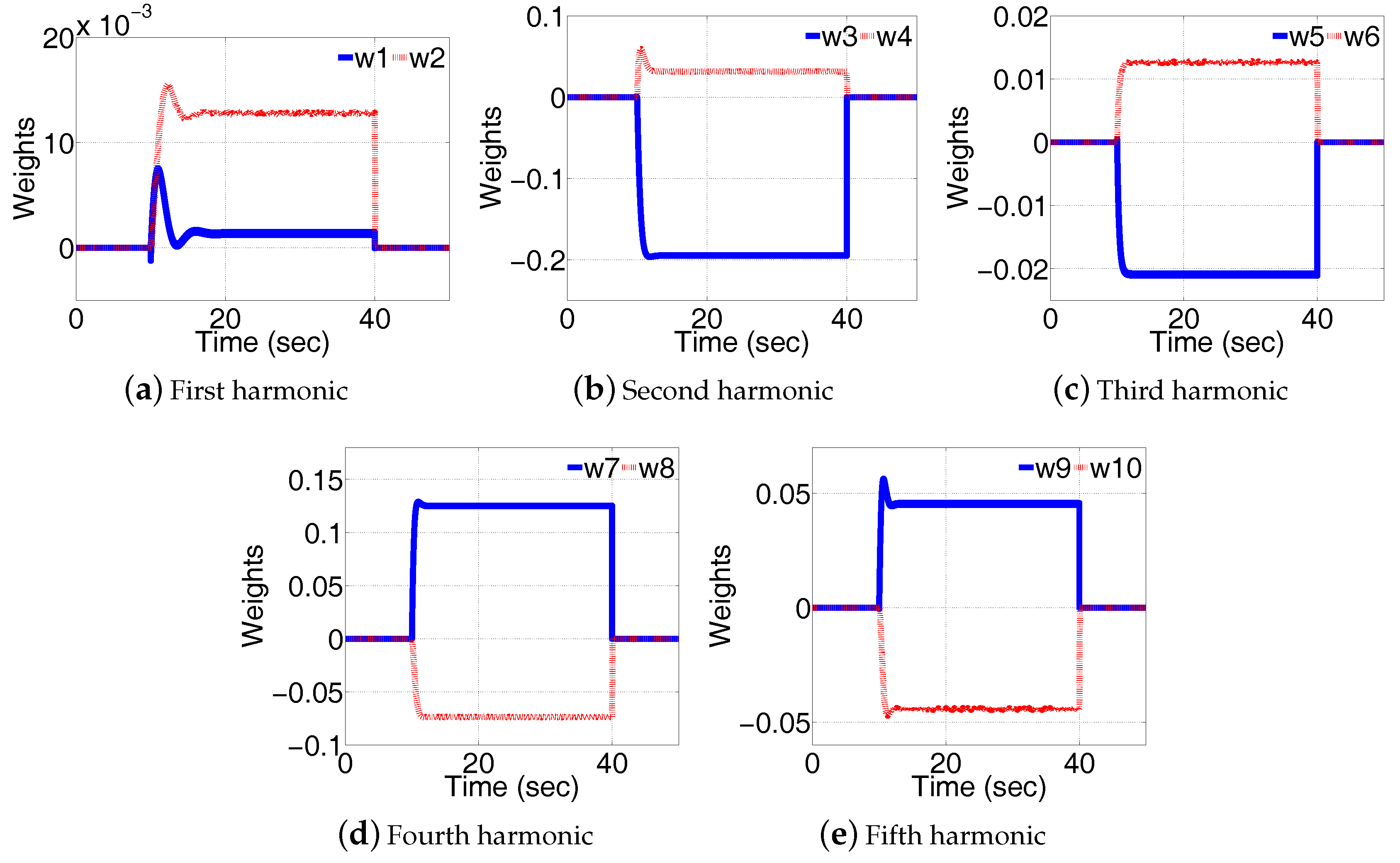
Figure 7a shows the simulated swash plate acceleration with the swash plate active vibration control. The active vibration control is activated at 10 s and deactivated at 30 s. In the simulation, the active vibration control successfully reduced added swash plate acceleration by controlling the swash plate. Figure 7b compares swash plate accelerations between “with active vibration control (AVC)” (20–30 s) and “without AVC” (40–50 s) in a frequency domain to see the effect of swash plate AVC. The frequency domain swash plate acceleration comparison shows that accelerations from the first harmonic frequency to the fifth harmonic frequency were effectively reduced with swash plate active vibration control. Figure 8 shows 10 adaptive filter weights corresponding to five harmonic frequencies of reference signal generators. The weights converged to stable values while performing swash plate active vibration control.
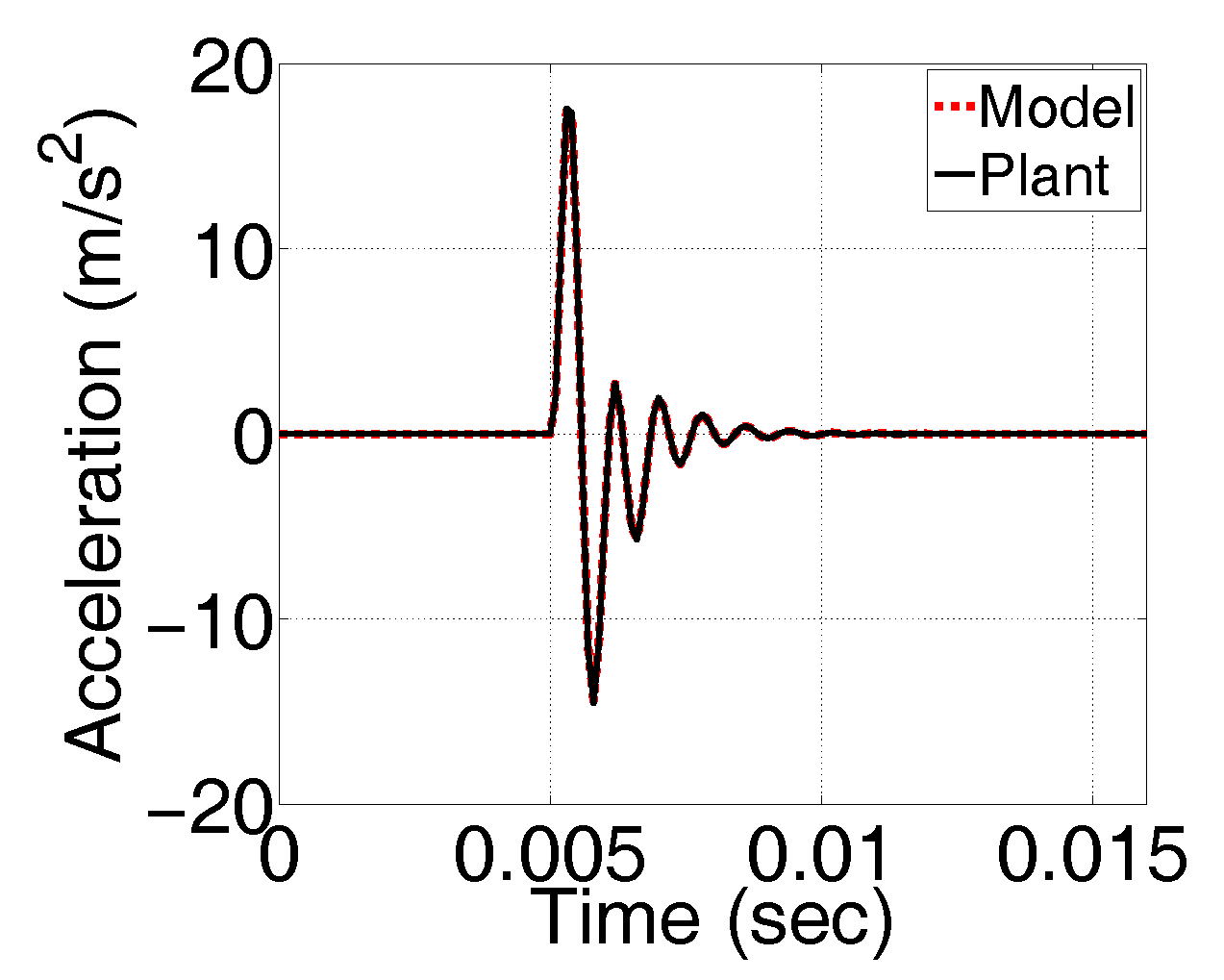
Instead of using delay units for compensation of the pump control system effects, estimated pump control system models were used to compensate pump control system dynamics and sensor/actuator delays in the MTNFxLMS algorithm. The off-line plant modeling technique modeled the pump control system response prior to use of the swash plate active vibration control. Figure 9 shows the off-line modeling simulation result using a linear pump control system model when an impulse input signal is applied at zero seconds. The offline plant modeling simulation was conducted using a 160-length adaptive FIR filter at 50 bar control pressure and 0 bar delivery pressure.
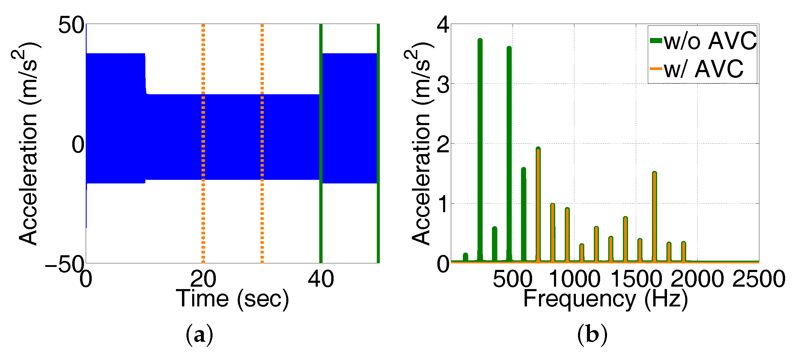
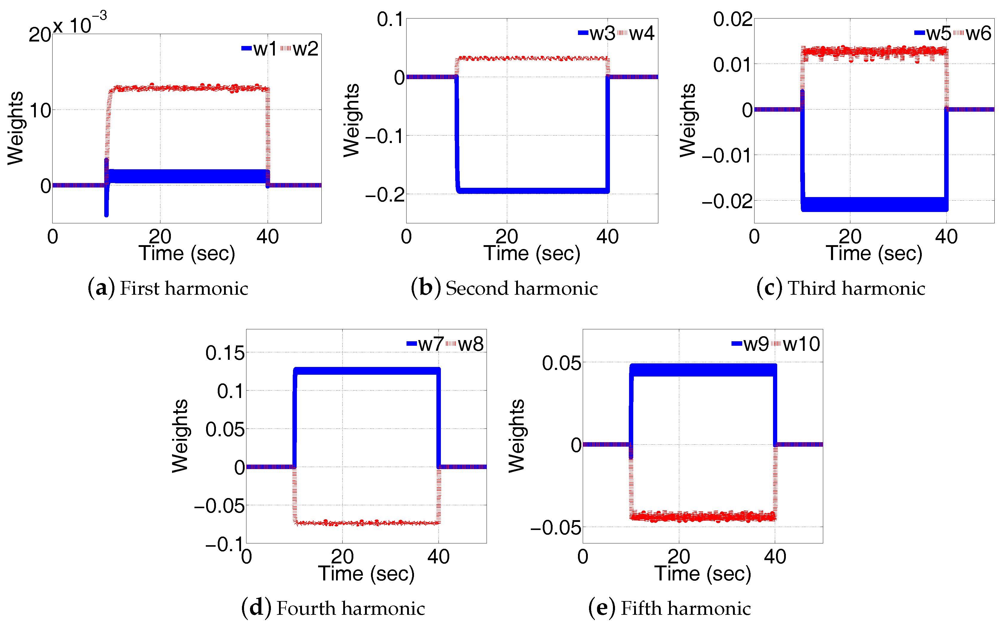
The simulated swash plate acceleration with a MTNFxLMS with an offline plant modeling algorithm is shown in Figure 10. Figure 10a shows a time domain acceleration change and Figure 10b presents a frequency domain acceleration comparison which demonstrates acceleration reduction at five harmonic frequencies. Adaptive filter weights corresponding to five harmonic frequencies were plotted in Figure 11. The weights demonstrated that the MTNFxLMS filter with an offline plant modeling algorithm can maintain a stable operation.
4. Active Vibration Control Pump Development
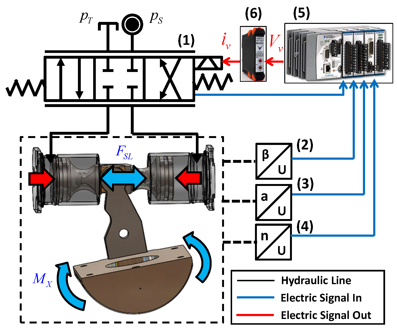
A 75 c/rev swash plate-type axial piston pump was selected as a reference machine for an experimental study of the swash plate active vibration control after consideration of operating conditions and sensor installations. The modified high-bandwidth pump control system consists of a high response direct drive servovalve (Parker D1FP, bandwidth 350 Hz at 5% input signal) (1); an electronic swash plate angle sensor (Contelec Vert-X 31E) (2); a swash plate acceleration sensor (3); a rotational speed sensor (4); a high performance real-time controller (NI cRIO-9033) (5); and a current-to-voltage converter (Viewpoint systems 64-VCC) (6) as shown in Figure 12.
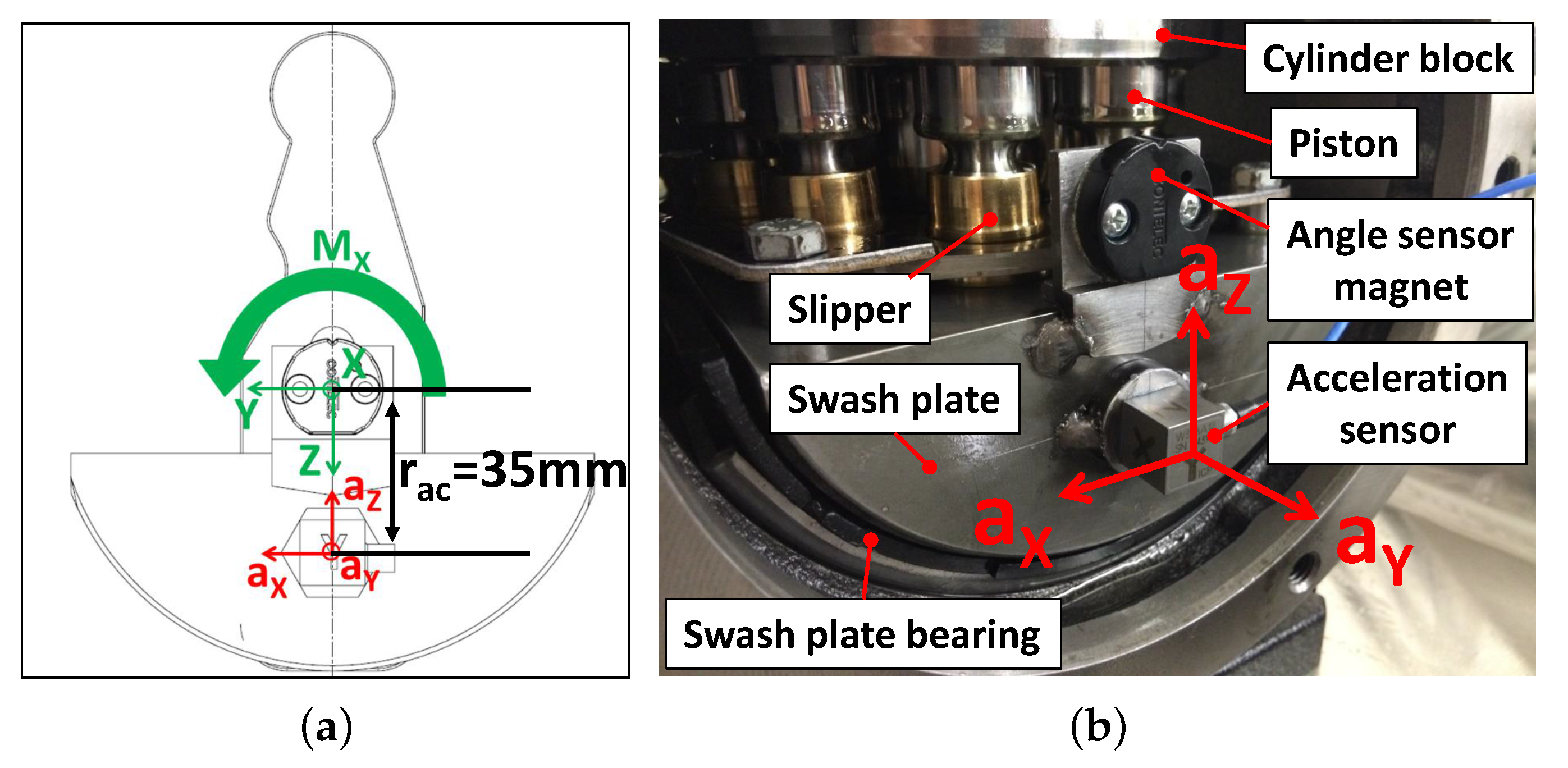
Direct swash plate acceleration measurements from the swash plate were planned for accurate swash plate vibration measurements. A piezoelectric type tri-axial acceleration sensor (PCB W356A12) was selected for the swash plate vibration measurement. The swash plate acceleration sensor was thread-mounted on the custom-made mounting base which was welded on the side of swash plate as shown in Figure 13.
The proposed swash plate active vibration controllers utilize a rotational speed to find the swash plate moment fundamental frequency which will be used for generating sinusoidal reference signals for feedforward-type adaptive LMS filters. Since the rotational speed of hydraulic pumps/motors fluctuate due to existing torque pulsations and flow ripples, an accurate rotational speed measurement is very important for the swash plate active vibration control performance and stability. A high accuracy rotational speed sensor (Heidenhain ROD426) which can output 9000 pulses per revolution was installed for the precise rotational speed measurement.
5. Swash Plate Vibration Experimental Test Results
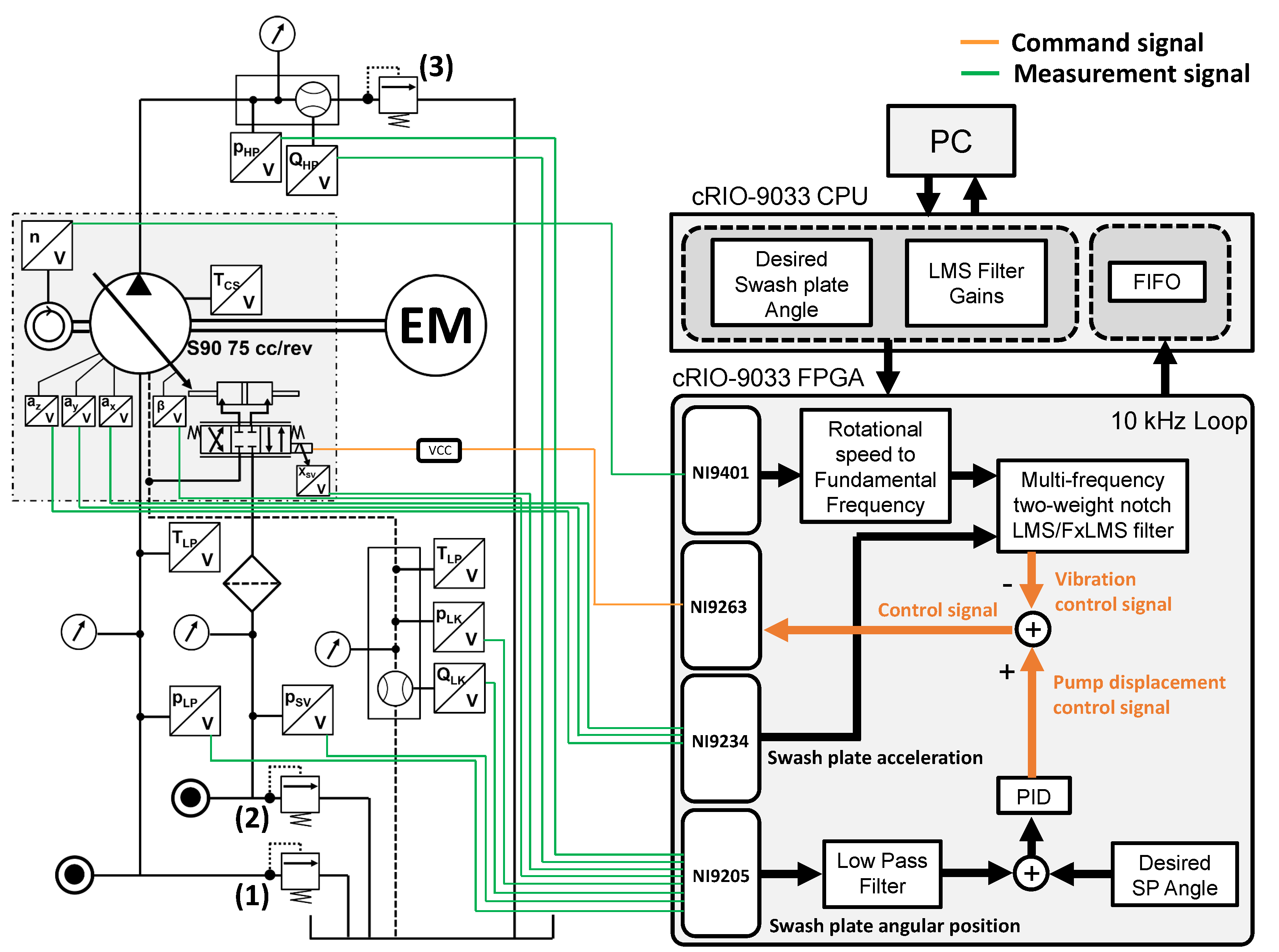
Figure 14 shows the hydraulic circuit used for active vibration control experimental tests. An electric motor was installed to drive the active vibration control pump. The pump inlet pressure and the control pressure can be adjusted individually by setting the relief valves (1) and (2) respectively. By setting the loading relief valve (3) at the pump discharge line, the pump delivery pressure was determined. The swash plate active vibration control system was implemented at 10 kHz sampling frequency through NI cRio-9033 chassis, NI9401 digital I/O module, NI9263 analog output module, NI9234 integrated electronic piezoelectric (IEPE) analog input module, NI9205 analog input module and LabVIEW FPGA. Figure 15 shows the installed active vibration control pump. The swash plate active vibration control experimental tests were performed for both TNLMS filter with delay unit compensation and TNFxLMS filter with offline modeling algorithms.
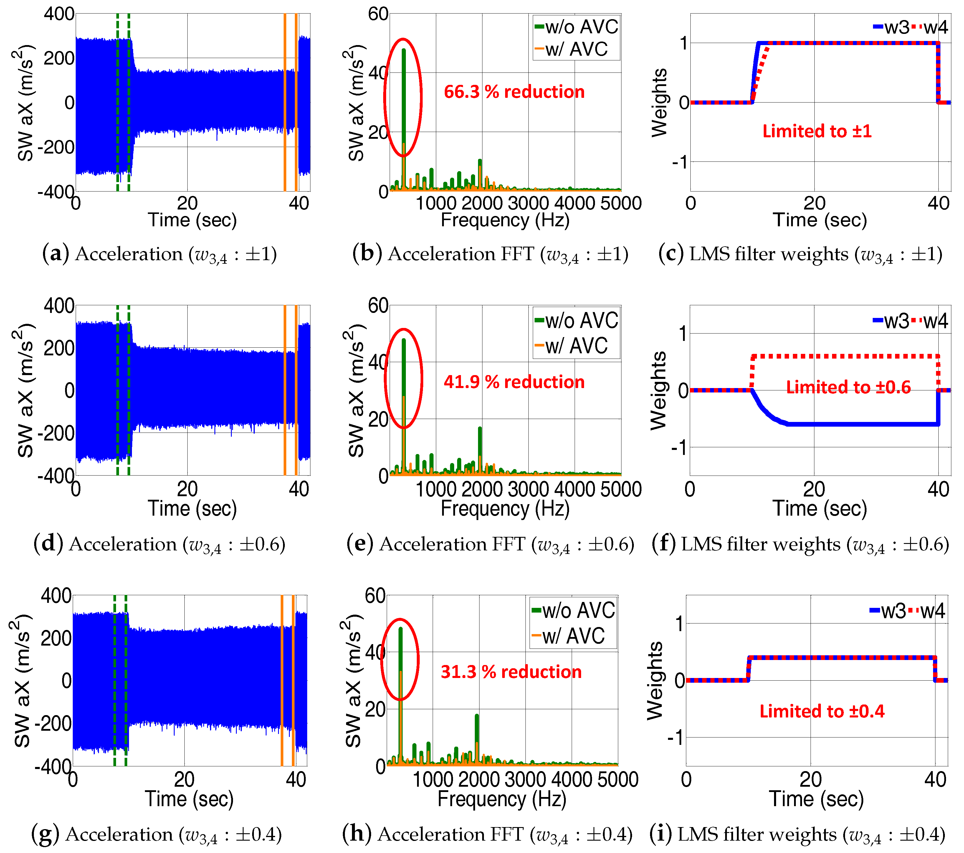
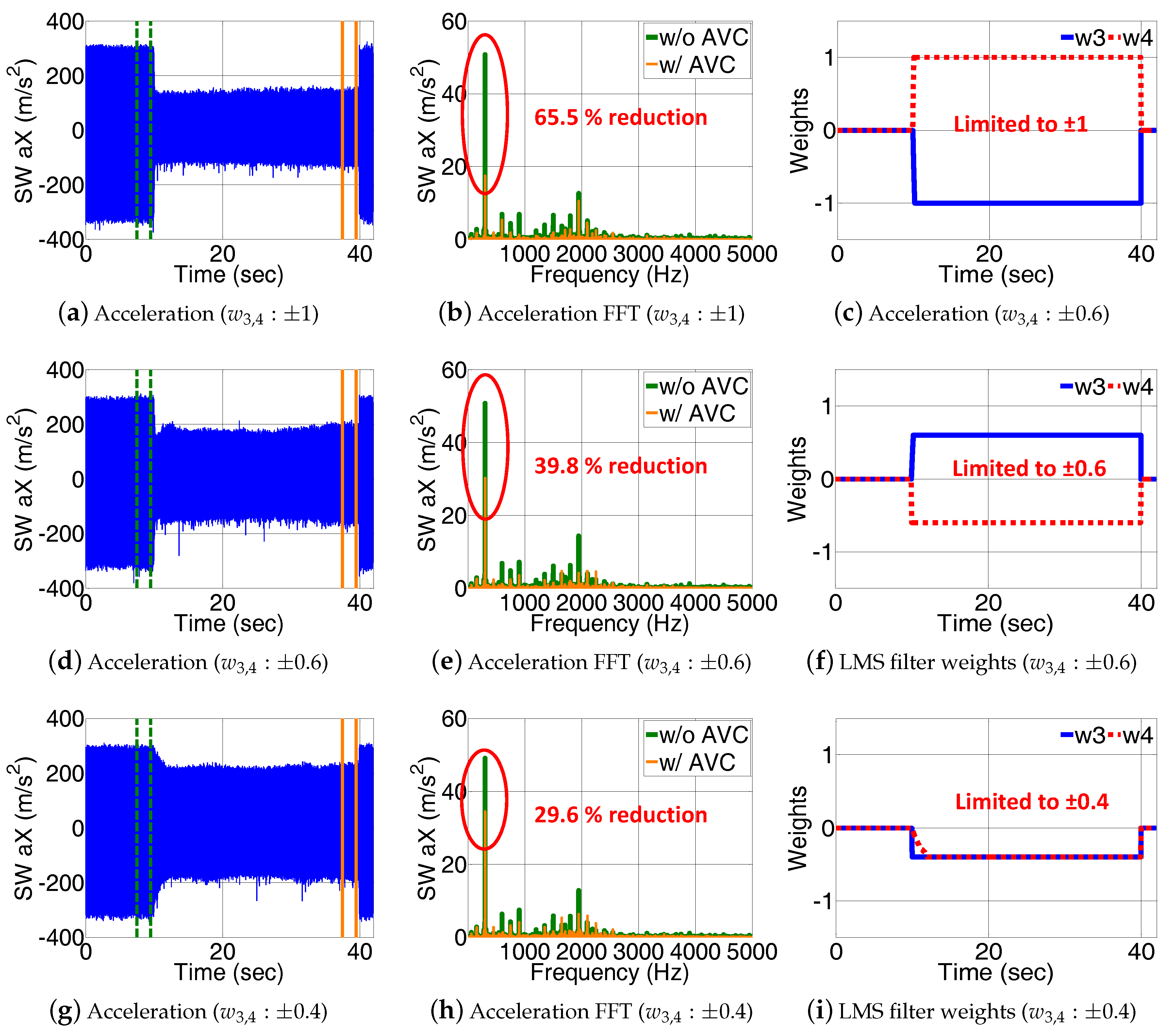
Figure 16 and Figure 17 show experimental test results at 1000 rpm rotational speed, 140 bar delivery pressure, 14.8° swash plate angle, and 25 bar inlet pressure setting. Only the second harmonic swash plate acceleration was reduced using the swash plate active vibration control since the second harmonic frequency is the most dominant acceleration component as shown in FFT plots below. Also, to adjust vibration reduction level, the adaptive LMS filter weights were limited as shown in Figure 16 and Figure 17. Different limits were applied to adaptive LMS filter weights of the first, second, and third rows in Figure 16 and Figure 17 such as 1, 0.6, and 0.4, respectively. Accordingly, the second harmonic swash plate accelerations showed approximately 66 percent, 40.8 percent, and 30.4 percent reductions at the first, second, and third rows respectively. When comparing measurement results to the simulation results shown in Figure 7 and Figure 10, one can observe the following: in simulation, the controller action influences/reduces only the targeted frequency vibration without impacting on other frequencies while the measurement shows a different behavior. The measured swash plate acceleration showed acceleration changes for a wide frequency range even when the controller was used to reduced only a single frequency swash plate vibration. Measurement results in Figure 16 and Figure 17 show that while reducing the second harmonic swash plate acceleration through the swash plate active vibration control, also higher harmonic accelerations showed amplitude reductions. The authors published a comparison of simulation and experimental test result for multi-frequency swash plate active vibration reduction [9].
6. Conclusions
The aim of this paper is to investigate the possibility of active vibration reduction using direct swash plate control. For the first time, advanced adaptive control concepts were investigated and proposed for the swash plate vibration reduction. The proposed active vibration control system was implemented and confirmed to be effective with measurements of swash plate accelerations. Adjustable acceleration reduction at targeted frequency was achieved using the weight-limited MTNLMS filter with delay unit compensation and the MTNFxLMS filter with the offline modeling algorithm. Test results utilizing the proposed controllers showed effective swash plate vibration reductions at targeted frequency. The developed high-bandwidth swash plate control system was realized using a high-speed direct drive servovalve, an electronic swash plate angle sensor, and the National Instrument cRIO-9033 controller via FPGA. A directly mounted tri-axial swash plate acceleration sensor enabled accurate vibration measurements utilized for the swash plate active vibration control.
Author Contributions
The work performed by Taeho Kim as a Ph.D. student in this work was supervised and mentored by Monika Ivantysynova. The preparation of this manuscript included contributions from both the authors.
Conflicts of Interest
The authors declare no conflicts of interest.
Nomenclature
| Symbols | Description | Units |
| M | Moment | Nm |
| a | Acceleration | m/s2 |
| Fundamental frequency of swash plate moment | Hz | |
| Sensor position from the rotational axis | m | |
| Swash plate lever arm length | m | |
| F | Force | N |
| p | Pressure | Pa |
| Q | Flow rate | m3/s |
| Control actuator piston area | m2 | |
| x | Control actuator displacement | m |
| m | Mass | kg |
| Hydraulic capacitance | m3/Pa | |
| Effective inertia of control system | kg·m2 | |
| Coefficient of Coulomb friction force | N | |
| Coefficient of viscous friction | N·s/m | |
| Coefficient of static friction force | N | |
| Bulk modulus of oil | Pa | |
| Leakage coefficient from control cylinder to case | m3/Pa·s | |
| V | Volume | m3 |
| Servovalve stroke | m | |
| Servovalve natural frequency | rad/s | |
| Frequency of reference signal | rad/s | |
| z | Number of pistons | - |
| Servovalve damping ratio | - | |
| e | Error of adaptive filter | - |
| d | Desired response of adaptive filter | - |
| y | Output of adaptive filter | - |
| W | Weight vector of adaptive filter | - |
| Convergence rate of adaptive filter | - | |
| L | Length of adaptive filter | - |
| Delay in signal | - | |
| Mean square error | - | |
| ∇ | Gradient operator | - |
| n | Rotational speed | rpm |
| T | Temperature | °C |
| V | Voltage | V |
| Acronyms | Description | |
| AVC | Active vibration control | |
| LMS | Least mean square | |
| FxLMS | Filtered-x least mean square | |
| TNLMS | Two-weight notch least means square | |
| TNFxLMS | Two-weight notch filtered-x least means square | |
| MTNLMS | Multi-frequency two-weight notch least means square | |
| MTNFxLMS | Multi-frequency two-weight notch filtered-x least means square | |
| FFT | Fast fourier transform | |
| VCC | Voltage to current converter | |
| EM | Electric motor | |
| SW | Swash plate | |
| FIFO | First-in first-out |
References
- Ivantysyn, J.; Ivantysynova, M. Hydrostatic Pumps and Motors; Akademia Books International: New Delhi, India, 2001. [Google Scholar]
- Edge, K. Designing quieter hydraulic systemssome recent developments and contributions. Jpn. Fluid Power Syst. Soc. 1999, 1999, 3–27. [Google Scholar] [CrossRef]
- Pettersson, M.; Weddfelt, K.; Palmberg, J. Prediction of structural and audible noise from axial piston pumps using transfer functions. In Proceedings of the Eighth Bath International Fluid Power Workshop on Design and Performance, Bath, UK, 15–17 September 1995. [Google Scholar]
- Ramdén, T.; Petter, K.; Palmberg, J.O. Reliability and sensitivity analysis of a condition monitoring technique. Jpn. Fluid Power Syst. Soc. 1996, 1996, 567–572. [Google Scholar] [CrossRef]
- Du, H.; Carlson, D.J. Fatigue life improvement of the roller swashplate bearing of an axial swashplate type piston pump. In Proceedings of the BATH/ASME Symposium on Fluid Power and Motion Control, Bath, UK, 10–14 September 2014. [Google Scholar]
- Masuda, K.; Ohuchi, H. Noise reduction of a variable piston pump with even number of cylinders. Jpn. Fluid Power Syst. Soc. 1996, 1996, 91–96. [Google Scholar] [CrossRef]
- Ohuchi, H.; Masuda, K. Active noise control of a variable displacement axial piston pump with even number of cylinders. Jpn. Fluid Power Syst. Soc. 1999, 1999, 79–84. [Google Scholar] [CrossRef]
- Ohuchi, H.; Masuda, K.; Osada, T. Noise reduction of a variable displacement axial piston pump by compensating the exciting force (experimental verification of the effect of compensation). In Proceedings of the JFPS International Symposium on Fluid Power, Nara, Japan, 12–15 November 2002; pp. 76–81. [Google Scholar]
- Kim, T.; Ivantysynova, M. Active vibration control of axial piston machine using higher harmonic least mean square control of swash plate. In Proceedings of the 10th IFK International Conference on Fluid Power, Dresden, Germany, 8–10 March 2016; pp. 91–104. [Google Scholar]
- Ahuja, K.; Stevens, J.C. Recent advances in active noise control. AIAA J. 1991, 29, 1058–1067. [Google Scholar] [CrossRef]
- Grabbel, J.; Ivantysynova, M. An investigation of swash plate control concepts for displacement controlled actuators. Int. J. Fluid Power 2005, 6, 19–36. [Google Scholar] [CrossRef]
- Widrow, B.; Walach, E. Adaptive Inverse Control A Signal Processing Approach; Reissue, Ed.; John Wiley & Sons, Inc.: Hoboken, NJ, USA, 2008. [Google Scholar]
- Kuo, S.M.; Morgan, D. Active Noise Control Systems: Algorithms and DSP Implementations; John Wiley & Sons, Inc.: Hoboken, NJ, USA, 1995. [Google Scholar]
- Widrow, B.; Glover, J.R., Jr.; McCool, J.M.; Kaunitz, J.; Williams, C.S.; Hearn, R.H.; Zeidler, J.R.; Eugene Dong, J.; Goodlin, R.C. Adaptive noise cancelling: Principles and applications. Proc. IEEE 1975, 63, 1692–1716. [Google Scholar] [CrossRef]
- Glover, J.R., Jr. Adaptive noise canceling applied to sinusoidal interferences. IEEE Trans. Acoust. Speech Signal Process. 1977, 25, 484–491. [Google Scholar] [CrossRef]
- Elliott, S.J.; Nelson, P.A. The Application of Adaptive Filtering to The Active Control of Sound and Vibration; University of Southampton Institute of Sound and Vibration Research: Southampton, UK, 1985. [Google Scholar]
- Widrow, B.; Stearns, S.D. Adaptive Signal Processing; Prentice-Hall: Englewood Cliffs, NJ, USA, 1985; Volume 1. [Google Scholar]
- Morgan, D.R.; Sanford, C. A control theory approach to the stability and transient analysis of the filtered-x LMS adaptive notch filter. IEEE Trans. Signal Process. 1992, 40, 2341–2346. [Google Scholar] [CrossRef]
Figure 1.
(a) High bandwidth pump control system; and (b) Simplified pump control system.

Figure 2.
Structure of the adaptive filter.

Figure 3.
(a) Two-weight notch LMS filter; and (b) Two-weight notch LMS filter with delay unit compensation.
Figure 3.
(a) Two-weight notch LMS filter; and (b) Two-weight notch LMS filter with delay unit compensation.

Figure 4.
(a) Two-weight notch FxLMS filter; and (b) Offline plant modeling algorithm.

Figure 5.
Multi-frequency two-weight notch LMS filter with delay unit compensation for swash plate active vibration control system.
Figure 5.
Multi-frequency two-weight notch LMS filter with delay unit compensation for swash plate active vibration control system.

Figure 6.
Multi-frequency two-weight notch filtered-X LMS filter with offline modeling for swash plate active vibration control system.
Figure 6.
Multi-frequency two-weight notch filtered-X LMS filter with offline modeling for swash plate active vibration control system.
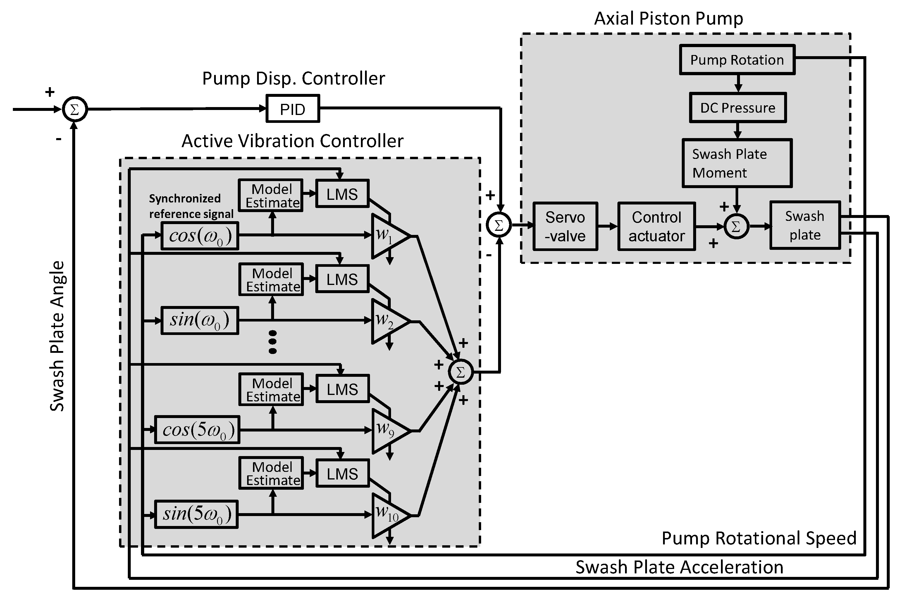
Figure 7.
Simulated swash plate acceleration using multi-frequency two-weight notch LMS filter with delay unit compensation (a) Time domain swash plate acceleration; and (b) Swash plate acceleration fast fourier transform (FFT).
Figure 7.
Simulated swash plate acceleration using multi-frequency two-weight notch LMS filter with delay unit compensation (a) Time domain swash plate acceleration; and (b) Swash plate acceleration fast fourier transform (FFT).
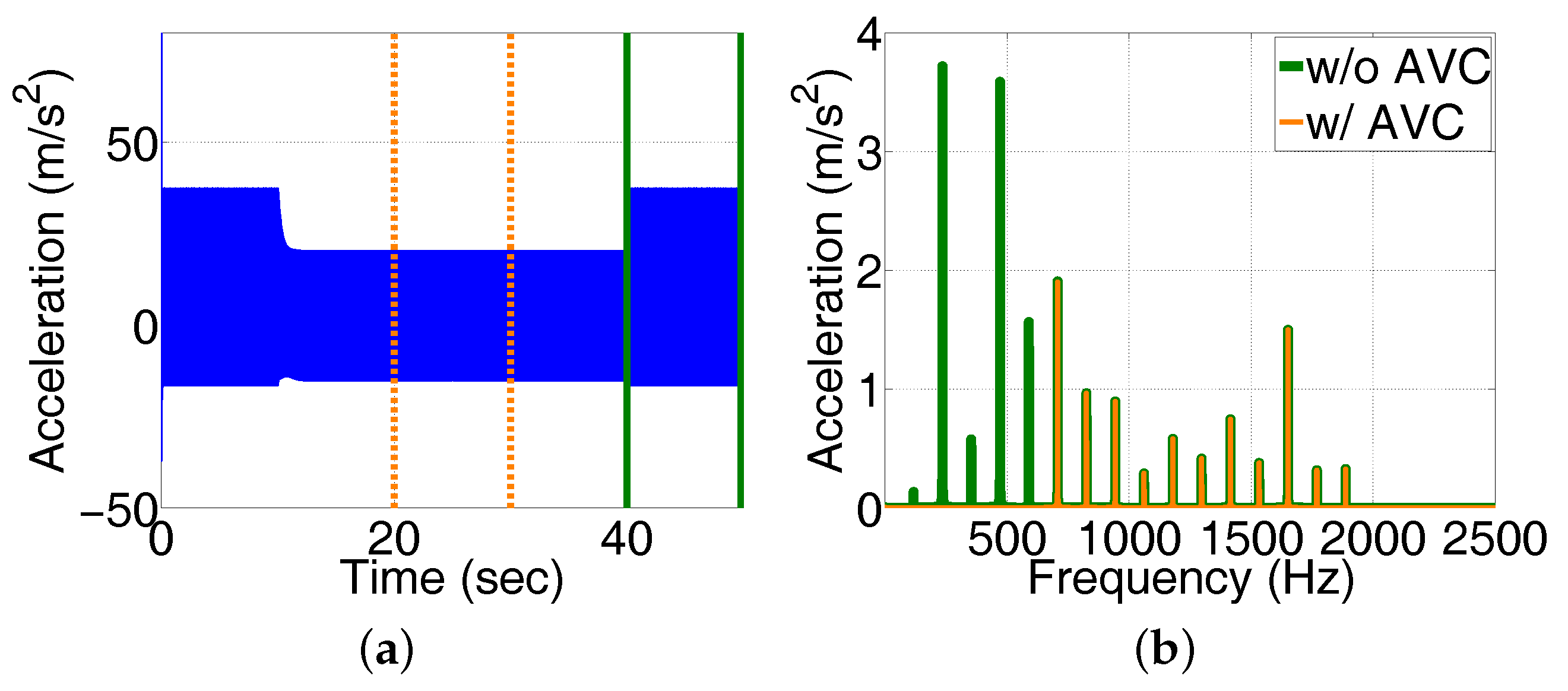
Figure 8.
Simulated adaptive LMS filter weights.

Figure 9.
Estimated swash plate acceleration impulse response using offline modeling algorithm.

Figure 10.
Simulated swash plate acceleration using multi-frequency two-weight notch FxLMS filter with offline modeling (a) Time domain swash plate acceleration; and (b) Swash plate acceleration FFT.
Figure 10.
Simulated swash plate acceleration using multi-frequency two-weight notch FxLMS filter with offline modeling (a) Time domain swash plate acceleration; and (b) Swash plate acceleration FFT.

Figure 11.
Simulated adaptive FxLMS filter weights.

Figure 12.
Schematic of the swash plate active vibration control system.

Figure 13.
Swash plate acceleration sensor installation (a) Swash plate acceleration sensor location; and (b) Installed swash plate acceleration sensor.
Figure 13.
Swash plate acceleration sensor installation (a) Swash plate acceleration sensor location; and (b) Installed swash plate acceleration sensor.

Figure 14.
Test rig hydraulic circuit.

Figure 15.
Active vibration control pump installation in the semi-anechoic chamber.
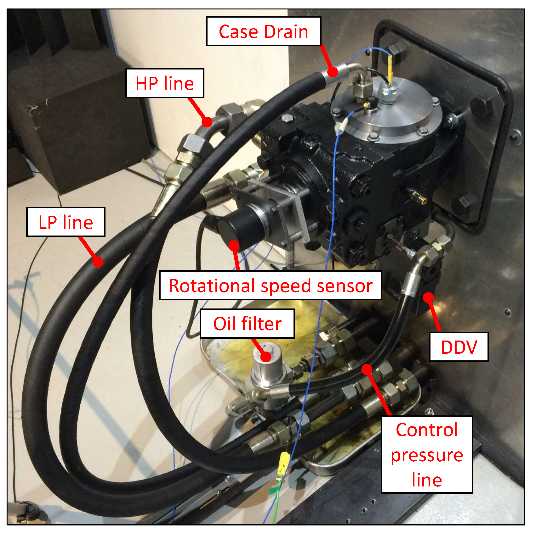
Figure 16.
Swash plate active vibration control experimental test results using a two-weight notch LMS (TNLMS) filter with delay unit compensation (speed: 1000 rpm, delivery pressure: 140 bar).
Figure 16.
Swash plate active vibration control experimental test results using a two-weight notch LMS (TNLMS) filter with delay unit compensation (speed: 1000 rpm, delivery pressure: 140 bar).

Figure 17.
Swash plate active vibration control experimental test results using a TNFxLMS filter with offline modeling (Speed: 1000 rpm, Delivery pressure: 140 bar).
Figure 17.
Swash plate active vibration control experimental test results using a TNFxLMS filter with offline modeling (Speed: 1000 rpm, Delivery pressure: 140 bar).

© 2017 by the authors. Licensee MDPI, Basel, Switzerland. This article is an open access article distributed under the terms and conditions of the Creative Commons Attribution (CC BY) license (http://creativecommons.org/licenses/by/4.0/).
Share and Cite
MDPI and ACS Style
Kim, T.; Ivantysynova, M. Active Vibration Control of Swash Plate-Type Axial Piston Machines with Two-Weight Notch Least Mean Square/Filtered-x Least Mean Square (LMS/FxLMS) Filters. Energies 2017, 10, 645. https://doi.org/10.3390/en10050645
AMA Style
Kim T, Ivantysynova M. Active Vibration Control of Swash Plate-Type Axial Piston Machines with Two-Weight Notch Least Mean Square/Filtered-x Least Mean Square (LMS/FxLMS) Filters. Energies. 2017; 10(5):645. https://doi.org/10.3390/en10050645
Chicago/Turabian StyleKim, Taeho, and Monika Ivantysynova. 2017. "Active Vibration Control of Swash Plate-Type Axial Piston Machines with Two-Weight Notch Least Mean Square/Filtered-x Least Mean Square (LMS/FxLMS) Filters" Energies 10, no. 5: 645. https://doi.org/10.3390/en10050645
Note that from the first issue of 2016, this journal uses article numbers instead of page numbers. See further details here.