Article

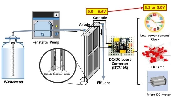
Electricity Production by the Application of a Low Voltage DC-DC Boost Converter to a Continuously Operating Flat-Plate Microbial Fuel Cell

1
School of Chemical and Biomolecular Engineering, Pusan National University, Jangjeon-Dong, Geumjeong-gu, Busan 46241, Korea
2
Sustainable Environment Research Centre (SERC), Faculty of Computing, Engineering and Science, University of South Wales, Pontypridd CF37 1DL, UK
3
The MFC Research and Business Development (R&BD) Center, K-water Institute, Jeonmin-Dong, Yuseong-Gu, Daejeon 34045, Korea
4
Department of Civil and Environmental Engineering, Pusan National University, Jangjeon-Dong, Geumjeong-gu, Busan 46241, Korea
5
Department of Natural Resources and Environmental Engineering, Hanyang University, Seoul 04763, Korea
*
Author to whom correspondence should be addressed.
Energies 2017, 10(5), 596; https://doi.org/10.3390/en10050596
Submission received: 16 February 2017 / Revised: 25 March 2017 / Accepted: 24 April 2017 / Published: 29 April 2017
(This article belongs to the Section I: Energy Fundamentals and Conversion)

Abstract

:
An ultra-low voltage customized DC-DC booster circuit was developed using a LTC3108 converter, and used continuously on a flat-plate microbial fuel cell (FPM) system. The boost converter successfully stepped up the microbial fuel cell (MFC) voltage from ~0.5 V to 3.3 and 5.0 V of outputs. The designed circuit and system displayed the dynamic variations of the source FPM as well as the output voltage through the designed three connection points within the booster circuit. The source MFC voltage was interrelated with the booster circuit and its performance, and it adapted to the set points of the booster dynamically. The maximum output power density of the MFC with the DC-DC booster circuit was 8.16 W/m3 compared to the maximum source FPM input power of 14.27 W/m3 at 100 Ω, showing a conversion efficiency of 26–57%, but with a 10-fold higher output than that of the source voltage. The combined LTC3108 with FPM supplied power for electronic devices using synthetic and real domestic wastewater. This report presents a promising strategy for utilizing the electrical energy produced from MFCs, and expands the applicability of bioelectrochemical systems with an improved energy efficiency of the present wastewater treatment system.

Graphical Abstract

1. Introduction

Microbial fuel cells (MFCs) use electrochemically active microorganisms as a biocatalyst for electricity generation from a range of biodegradable organic materials. Since the 1990s, ecofriendly and sustainable wastewater treatment processes using MFC technologies have been suggested and studied extensively for bio-electricity production. The power generation depends mainly on the reactor design, internal resistance, microbial species on the anode, type of organic material, and medium composition [1,2]. The theoretical voltage of a MFC is determined by the equilibrium potentials of the half-cell redox reactions occurring at the cathode and anode [3]. On the other hand, most MFC systems typically generate an open circuit voltage well below 0.7 V due to overpotential losses, which include mass transport limitation of reactants (oxygen at the cathode and biodegradable substrate at the anode), activation losses in sustaining the electrochemical reactions, and ohmic losses related to the limitations of the internal ion and electron transport. The voltage of a MFC is well below the minimum operational value of many devices, such as sensors and electronics.
Various techniques and strategies have been employed to increase the cell voltage of a MFC system and achieve practical power quality for the operation of commonly available devices, such as complementary metal-oxide-semiconductor (CMOS)-based integrated circuits [4]. The primary method involves electrically stacking MFC reactors in series and/or parallel. As a result, the total voltage and current can be multiplied using a method similar to that used in chemical batteries. Shin et al. [5] stacked five MFCs with bipolar plates and tested their performance in terms of power and efficiency. When ferricyanide was used as the catholyte, the reactors produced 0.13 mW/cm2 (based on the electrode surface area) using a 1 F super-capacitor to store the electrical energy. After an acclimation period, the voltage of the stacked MFC system increased slowly to 2.3 V. Aelterman et al. reported that a serial and parallel connection of six MFC units produced up to 2.02 V (228 W/m3) with a current of 255 mA (corresponding to 248 W/m3) [6]. The high output power density and stability were maintained under continuous feeding. Oh and Logan [7], however, reported that each of the directly stacked cells showed unavoidable voltage differences from each other during operation due to the different concentrations of the carbon source and other operational parameters. Voltage reversal can be expected if one cell does not produce a comparable voltage to its neighboring cells, which will have detrimental effects on the unit cell and cause changes to the bacterial community on the electrode, eventually disabling the entire stacked system. These results suggest that it may be difficult to maintain stable performance from the directly stacked MFCs because they depend on a dynamic biocatalyst with live cell microorganisms, which are less predictable than conventional catalysts, such as that in a PEM fuel cell. Ieropoulos et al. [8] reported that Ecobot-II can be powered by capacitor-based circuit system with MFCs. They also developed a MFC type real-time electrical configuration with progressive switching of in-parallel elements to in-series units while obtaining higher energy transfer in a MFC stack system [9].
The other strategy is to use a boost converter that can increase the individual cell voltages in an MFC system to a point where a practical and commercially usable voltage can be delivered to operate common electronic and sensor devices. A typical MFC generates low voltages, often not exceeding ~0.7 V (open circuit voltage, OCV), and much lower voltage than the OCV is obtained in practically operating cells from which the current is drawn by an external (usually resistive) load. Therefore, a customized DC-DC boost converter that can operate from ultra-low voltages might be suitable for MFC applications. DC-DC systems may also convert a fluctuating DC input into a controlled and stable output, particularly when the input source voltage is affected dynamically by the operating conditions, such as temperature, organic loading rate, etc. DC-DC boost converters were reported to produce more than 3.0 V, which is sufficient to operate some electronic devices, such as wireless sensors [10,11,12]. Wu et al. designed and fabricated a DC-DC booster circuit using an oscillator/FET (field-effect transistor) to minimize the power consumption within the components [13]. The booster delivered a maximum voltage of more than 3 V from the source voltage of a mini-MFC, ranging 0.2 to 0.4 V.
Park et al. also developed an energy harvesting system based on a synchronous boost converter (SBC) that enhanced the energy conversion efficiency by more than 73% compared to the conventional diode based boost converter (DBC) [14]. Adami et al. [15] designed a novel DC-DC converter topology based on the Armstrong oscillator (commonly used for commercial boost converters), and reported output voltages ranging from 2 to 7.5 V from a MFC generating an OCV of only 0.475 V. The maximum power delivered was approximately 100 µW with an efficiency of 58%. On the other hand, it has been difficult to obtain more than 70% conversion efficiency from the ultra-low boost converter [12]. Upgrading the output voltage from the MFCs is highly desirable in the context of utilizing sustainable and renewable bioelectricity produced from a range of biodegradable biomass substrates. In a recent review by Wang et al. [16], a circuit-based power management system (PMS) for MFCs was suggested to be crucial for scale-up and realistic applications of MFCs. The PMS works well under a very low input voltage (0.18 V) and can successfully drive power for wireless sensor devices [17]. In the previous reports, however, the interrelation of MFC and booster circuit has not been addressed. Therefore, it is difficult to provide information to design and operate the circuit for further modification.
In this study, an ultra-low voltage DC-DC conversion device employing LTC3108 was developed for a MFC, and the operating conditions of a continuously operated flat plate MFC (FPM) fed with synthetic and domestic wastewater were investigated. The fluctuations of the voltage applied to the boost converter conduit (input to booster) and the boosted output voltage were compared simultaneously using three designed connection points within the boost circuit. In addition, the MFC voltages were compared to investigate the operational effects of the boost converter. A study of the dynamic interrelation between the booster and MFC provides useful information on the extraction of electrical energy from real wastewater. The feasibility of powering electronic equipment using the boosted voltage and power from FPM, was demonstrated using a low power mechanical clock movement, a LED lamp, and micro DC motor.

2. Results

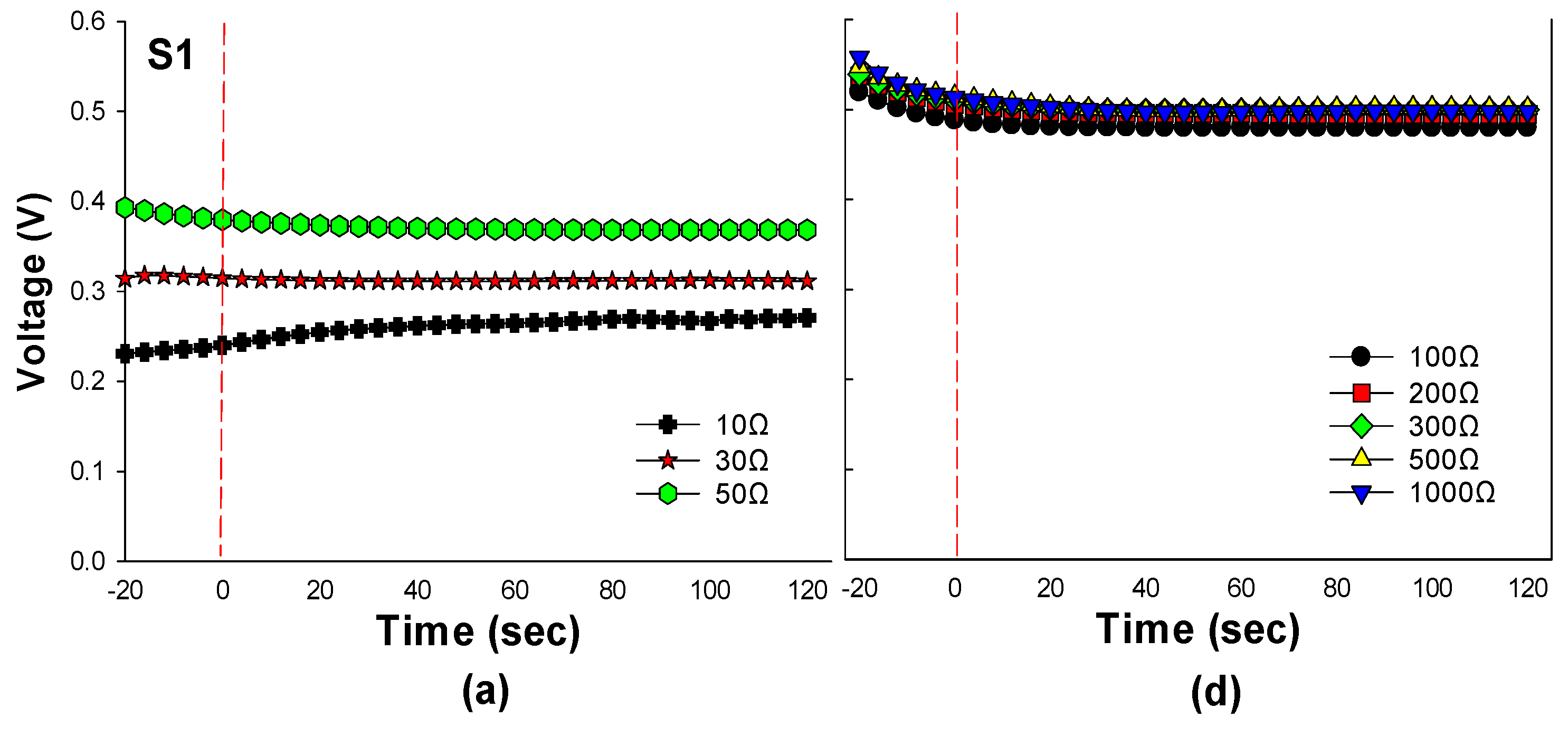
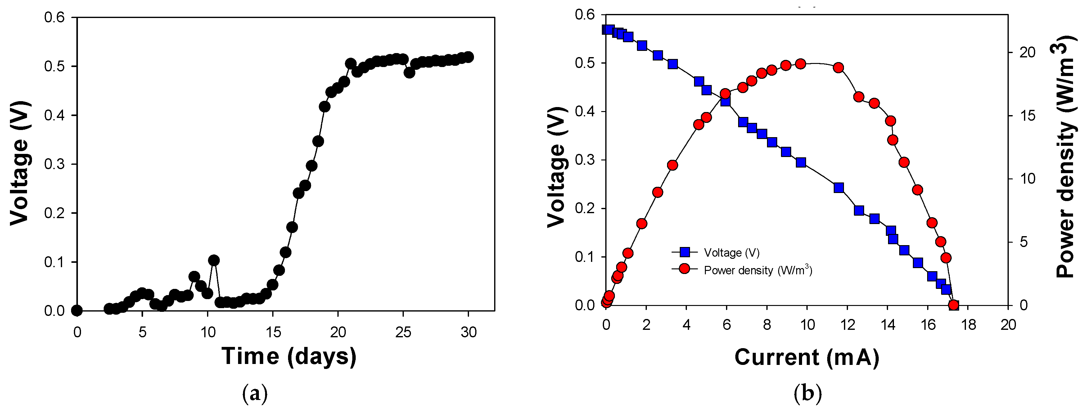
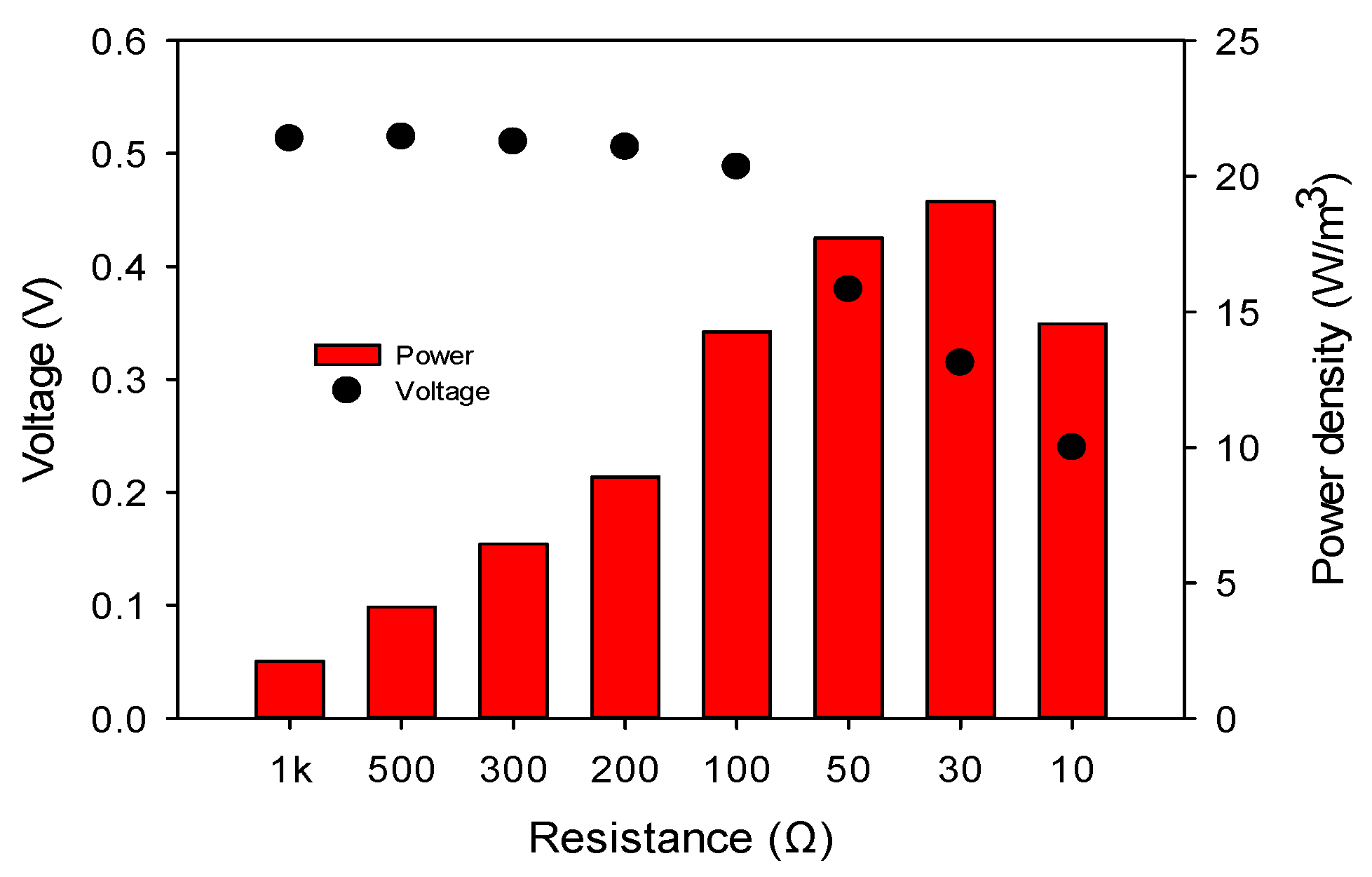
2.1. Enrichment and Polarization Curves for Flat-Plate Microbial Fuel Cell (FPM)

Electricity generation from the FPM with a sludge inoculum became evident after 50 h of batch mode operation, which was operated for a further seven days to achieve the enrichment and stabilization. The voltage increase showed a typical exponential growth pattern, indicating the development of an electrochemically-active community on the anode electrode (Figure 1a). The FPM was then switched to continuous mode for subsequent experiments. The power density curve of the FPM was measured to examine the effects of the DC-DC booster. The polarization curve showed that the maximum power density was 19.1 W/m3 based on a reactor volume of 150 mL at 9.5 mA under continuous operation after 30 days of operation. (Figure 1b).

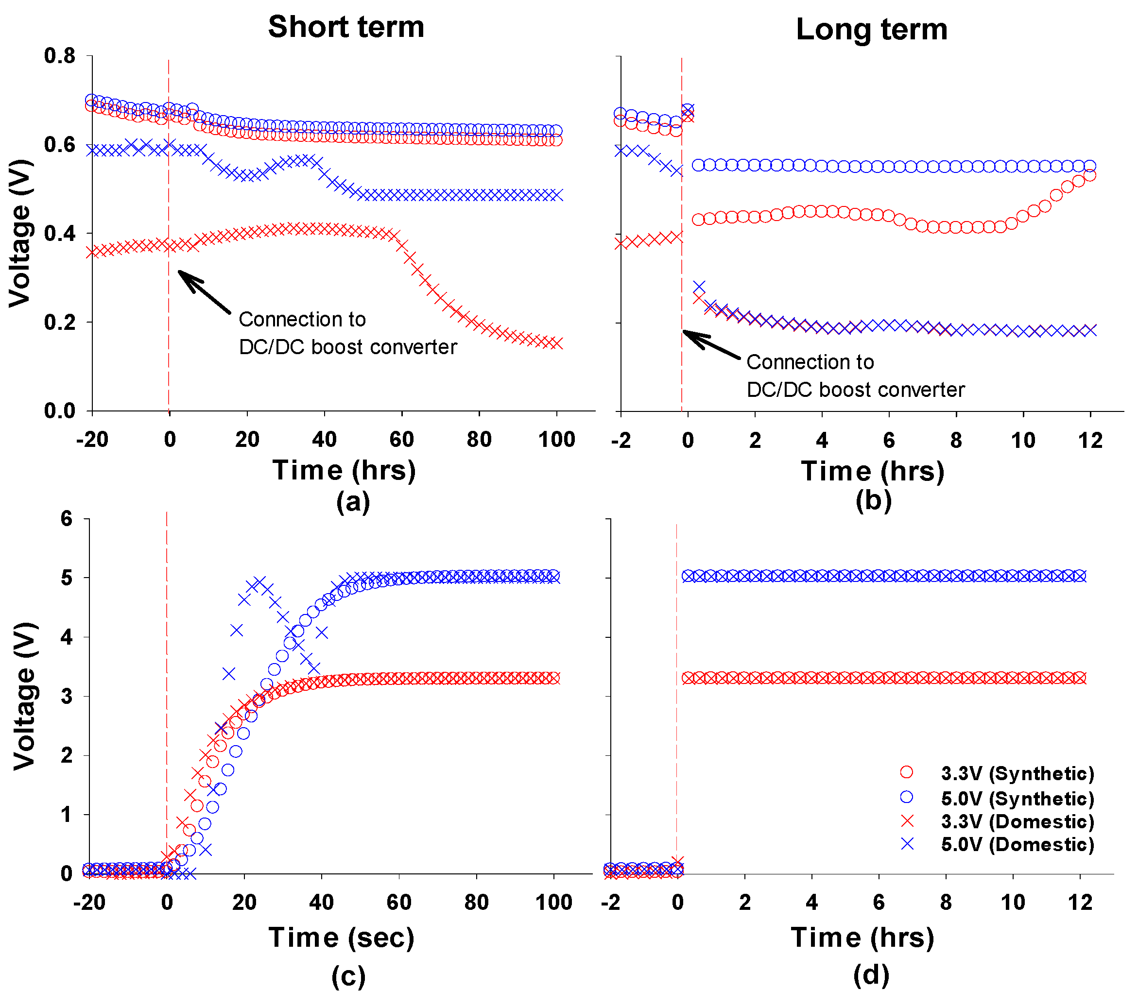
2.2. Performance of DC-DC Booster with FPM

The LTC3108 specifications (from the supplier) indicate that the device can boost source (or input) voltages greater than or equal to 100 mV [18]. Although the device has been used in solar panel systems and other low DC power electronics, it has not been applied to a MFC or a continuously operating FPM system. Therefore, it is necessary to examine the stability and applicability of the developed DC-DC booster at the minimal source voltages from a MFC system, such as the FPM used in this study. The voltage measurement modules were connected to the three connection points, as shown in Figure 2, i.e., the source voltage of FPM (S1), input (or voltage introduced) to the DC-DC booster (S2), and the boosted output voltage for practical application (S3). The voltage from the FPM and its dynamic changes through the DC-DC booster module could be investigated and compared simultaneously.
Figure 3 shows the voltage increases using the developed DC-DC booster circuit. To examine the effects of the changes in source voltage, the FPM was connected manually to the load resistances, ranging from 10 to 1000 Ω, using a resistance box. When a lower resistance (10 to 50 Ω) was connected, the FPM produced stable input voltages between 0.25 and 0.4 V (Figure 3a) as closed circuit voltages (CCV). Connection of the DC-DC booster decreased the voltage sharply at the connection point to the circuit (S2), and stabilized to 160 mV (50 Ω), 80 mV (30 Ω), and 40 mV (10 Ω), respectively (Figure 3b). The FPM connected to 50 Ω (400 mV of source voltage) increased the boosted voltage through the DC-DC booster (S3) by 1.0 V, whereas lower input source voltages (<0.4 V) did not show any noticeable output voltage improvement (Figure 3c).
The DC-DC booster successfully increased the output voltage to more than 5 V (S3, Figure 3f) when the FPM produced source voltages over 0.488 V using higher resistances (over 100 Ω) (S1, Figure 3d), which was determined and anticipated by the designed circuit. The input voltage to the DC-DC booster showed a more rapid decrease to less than 200 mV (S2, Figure 3e). Similar results were obtained with the boost circuit set to 3.3 V (data not shown). This suggests that the DC-DC boost converter actively extracts the input voltage from the FPM by approximately 0.4 V, boosting to the set points. If the source voltage is insufficient, i.e., below 0.4 V, the booster circuit fails to boost the output voltage, as shown in Figure 3c. Therefore, the DC-DC booster developed with LTC3108 requires a minimum source voltage of more than ~0.49 V as the working potential. These results also suggest that the booster does not affect the source voltage of the FPM directly over relatively short time periods (e.g., several minutes), but after the longer term operation, the DC-DC booster actively consumes and drains power within the circuit to boost the output voltage once the booster is introduced, as shown in the Figure 4a,b.

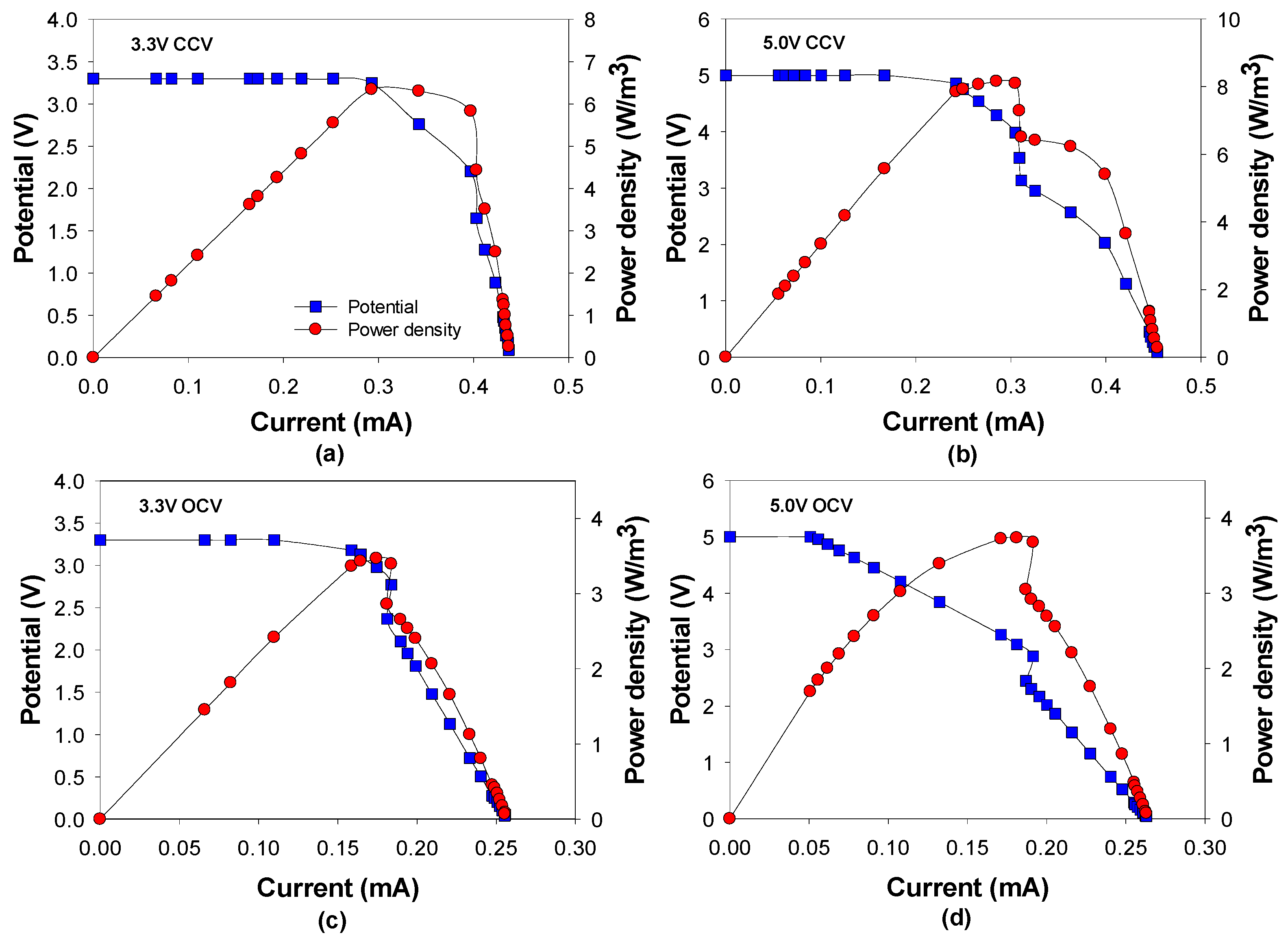
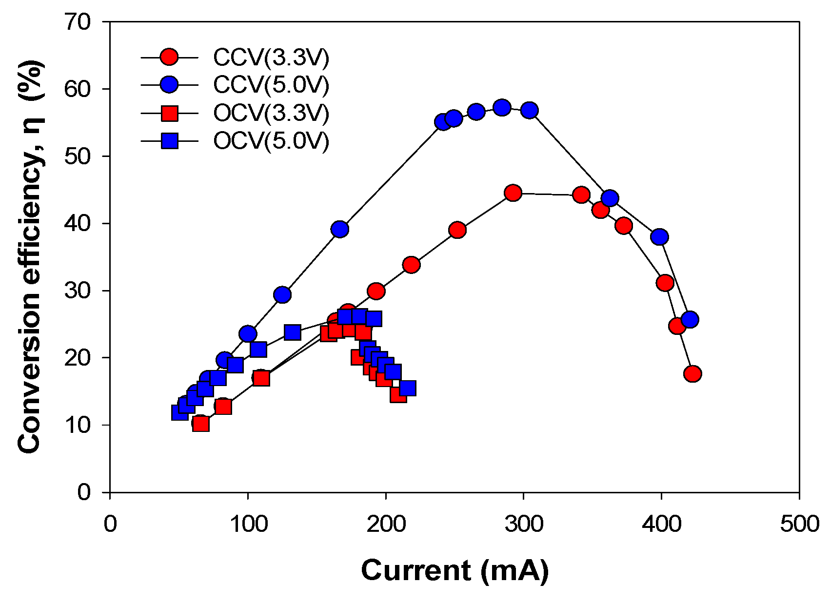
2.3. Comparison of the Closed and Open Circuit with the DC-DC Booster

The boosting efficiency, output voltage, and maximum power generation were evaluated to compare the CCV and OCV (without a load resistance) operations when connected to the developed DC-DC boost converter. Figure 5 presents power and voltage generation according to internal resistances from 10 to 1000 Ω which were estimated by linear sweep voltammetry. The maximum power generation was 19.07 W/m3 on 30 Ω, but the DC/DC boost converter did not startup below 100 Ω, as shown in Figure 3c. These results indicate that the circuit can boost an input source of over 0.49 V associated with a 100 Ω load (Figure 5). Therefore, a 100 Ω was applied to the boost circuit on the CCV and OCV in the followed investigations.
The DC-DC boost converter was set to a voltage output of 3.3 and 5.0 V on the selector terminals with the same connection configuration to measure the circuit voltage (Figure 6).
Initially, the FPM DC-DC boost converter was operated continuously in the CCV state. The voltage boosted through the designed circuit was connected to various resistances, and the maximum power production was investigated. When the boost circuit was set to 3.3 V, a maximum power density of 6.34 W/m3 at 0.29 mA (0.95 mW on the power curve and 3.15 V) was generated, whereas an output voltage of 5.0 V with a power density of 8.16 W/m3 at 0.29 mA (1.22 mW at 4.29 V) was observed in the closed circuit (Figure 6a,b). During OCV operation, 3.3 and 5 V resulted in a maximum power density generation of 3.47 mW/m3 at 0.18 mA (0.52 mW and 2.98 V of the boosted output voltage) and 3.74 mW/m3 at 0.18 mA (0.56 mW), respectively (Figure 6c,d).
The DC-DC booster with the CCV connection generated power densities of 2–2.5 times higher than those of the OCV. The estimated conversion efficiencies based on the maximum power density on a measured power curve were between 26–57% compared to the source FPM maximum power point values (Figure 7 and Table 1).

2.4. Effect of Different Wastewaters on Boosting the Power from Flat-Plate MFC

MFC systems are being studied for applications in wastewater treatment and in efforts to achieve simultaneous electrical energy recovery and efficient removal of organic contaminants. Most of the DC-DC boosters developed have been applied to relatively small scale batch reactors and/or using synthetic media. Therefore, this study applied the DC-DC boost converter to a continuously operated FPM with both pre-settled domestic and synthetic wastewater to examine the stability and effects of different types of wastewater feedstock. The FPM with the synthetic wastewater (1746 ± 136 ppm-COD; chemical oxygen demand) generated a stable output voltage of 0.6 V, while the domestic wastewater produced an unstable voltage, ranging from 0.35 to 0.59 V, which can be attributed to the variations in the influent COD concentration.
When the DC-DC booster circuit was connected, the input voltage was not affected significantly during the initial 100 s. On the other hand, the input voltage decreased within 10 min and was then stabilized to 0.57 V (when setting the demand to 5.0 V) and 0.43 V (setting to 3.3 V), while using synthetic wastewater; and 0.2 V (set to either 5.0 V or 3.3 V) while using domestic wastewater. A similar trend of the output voltages was maintained for one week of operation. The DC-DC booster circuit increased the output voltage successfully to the set point with both wastewater feed stock, even though the influent CODs were different. When using synthetic wastewater, the voltage output of the FPM decreased to less than that with domestic wastewater as a result of the higher COD concentration, and probably the higher current from the FPM (Figure 4). This suggests that the DC-DC booster under consideration actively drained the voltage and power sourced from the FPM, thereby reducing the input source potential for longer term operation.

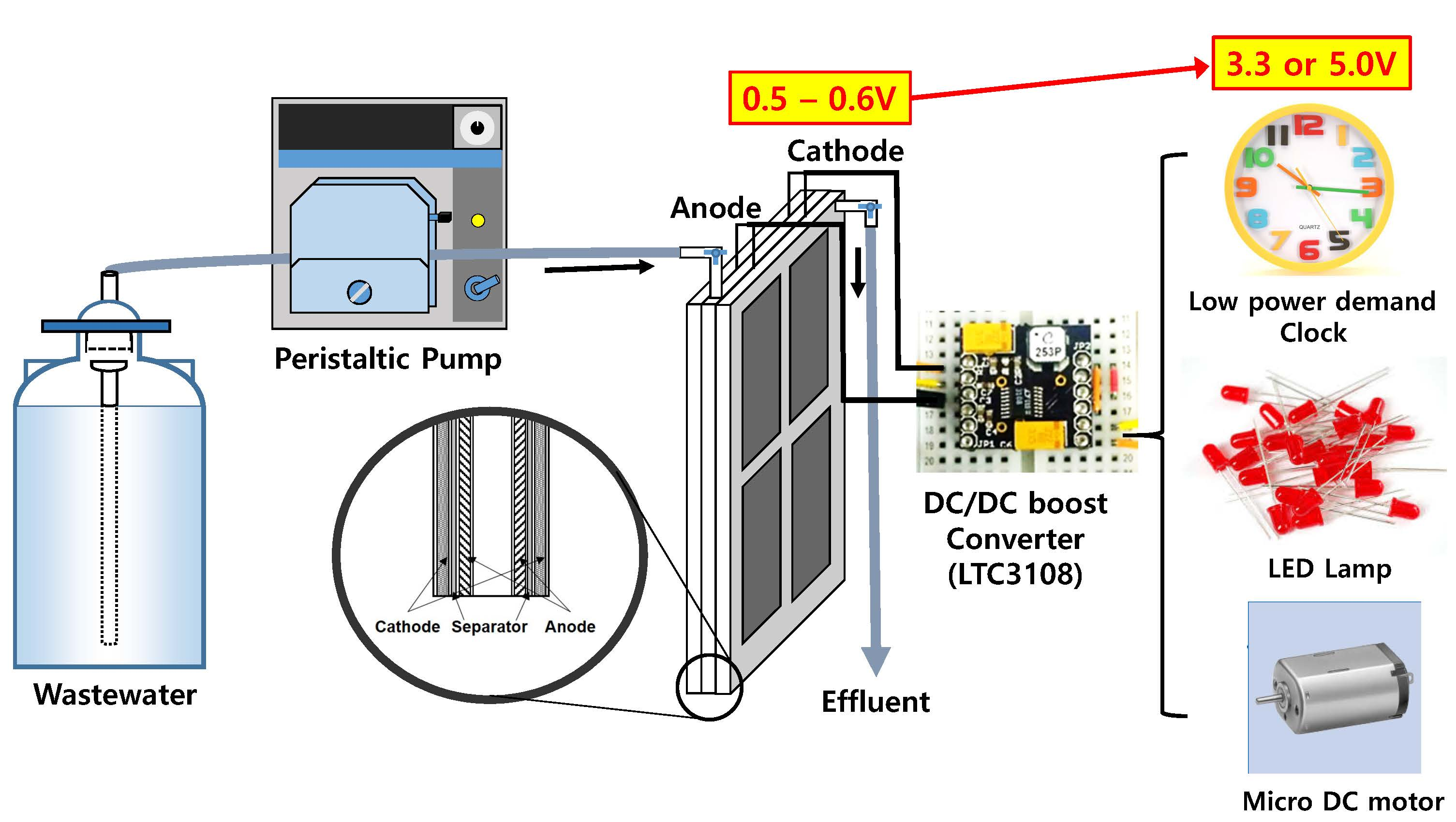
2.5. Operating Low Power Electronic Devices through the DC-DC Booster

To investigate the practical applicability of the voltage/power generated using the DC-DC booster circuit, low power demand electronics were powered by the FPM through the designed circuit. The single FPM generated approximately 0.6 V, whereas the dual FPM consisting of two serially-connected single FPMs generated approximately 1.1 V output. The single and dual FPM were connected to the DC-DC booster circuit, and set to output voltages of 3.3 and 5.0 V, respectively. The output voltage/power (S3) was connected to the electronic devices to be checked for operability.
The power and voltage from the combined FPM and DC-DC booster should be consistent and sufficient to operate electronic devices. Therefore, the low power demand electronics described in Section 2.4, which have different minimum operational power and voltage requirements, were tested for operational stability with the designed DC-DC booster. The power from the FPM only did not sustain and support any of the load devices except for the micro-motor. On the other hand, the DC-DC booster combined FPM expanded the operational range of the electronics to LED lamps and micro DC motors using synthetic and domestic wastewater. These results show that the developed DC-DC booster can expand the applicability of the power produced by MFCs (See Table 2).

3. Discussion

A low voltage DC-DC boost converter applicable to MFCs was developed using LTC3108, and was tested on a continuously operated FPM by treating synthetic and domestic wastewater. A previous study indicated that this DC-DC converter showed a low output voltage and power in a small-scale batch MFC system [19]. In the present study, however, the LTC3018-based converter was applied to an optimized FPM that produces a higher power density and coulombic efficiency in continuous operation. The voltages at three different connection points in the circuit, the source voltage of FPM (S1), the input voltage to the DC-DC booster (S2), and the boosted output voltage for practical application (S3), were investigated to determine the effects of the circuit. The increased voltages through the DC-DC booster achieved a set point of 3.3 and 5.0 V, which are perceived to be sufficient for practical applications. This was achieved when using both domestic and synthetic wastewater, and was demonstrated to operate a range of illustrative low power demand electronic devices as loads.

3.1. DC-DC Boosting Strategy for MFCs

Recently, MFC type power management systems (PMSs) with a DC-DC boost converter adopted from the conventional power conversion system have been investigated to overcome low voltage and power which are the intrinsic limitations of biological process [16]. Step-up converters can produce an output voltage greater than the input source voltage. Several booster converters have been developed and applied to MFCs, as summarized in Table 3, but most were limited to batch type reactor operations. The effects of employing voltage boosters on a MFC have not been studied by the methods used herein, and the change in voltage at different points in the combined MFC/booster system has not been investigated. Specific monitoring of the voltage changes within the circuit provides important information on the MFC and DC-DC booster combination, which can provide further scope for improving the voltage boosting performance. In this study, the three connection points (S1, S2, and S3) associated with the booster circuit were constructed, and the dynamic changes in the potential, which were in situ with the LabVIEWTM-associated data acquisition hardware (National Instruments™, Austin, TX, USA) were investigated.

3.2. Interrelation between the MFC and DC-DC Booster

The results showed that the booster converter does not affect the source MFC potential in the short term, but actively drains power at a relevant voltage after approximately 10 min when connected (Figure 3 and Figure 4). The source MFC voltage is interrelated to the booster circuit and its performance, and is adapted dynamically to the set points of the booster, as shown in Figure 4b. These results suggest that the MFC may adapt to this live cell-electronic circuit hybrid system, and allow stabilization to the equilibrium conditions induced by the booster circuit. The long-term drift or changes in the MFC performance induced by the DC-DC booster are interesting because they could provide a strategy for further optimization.
Recent studies of maximum power point tracking (MPPT), which regulates the external resistance according to dynamic cell potential changes, suggest an adaptation/enrichment strategy for electroactive microorganism on an electrode, and may support the argument that the MFCs can adapt to automatically-regulated external circuitry and the moderate operating conditions imposed on them [4,20]. Such active control may improve their applicability by extracting the increased electrical energy over unregulated systems, and further enhance the MFC performance. Increased electrochemical activity may also further improve the treatment efficiency in the case of COD removal for wastewater applications. Another advantage of DC-DC boosting is to stabilize the output voltage despite the fluctuations induced by the MFC voltage due to the variable organic loading rates, temperature, and variations under other operating conditions. Stabilization of the output voltage/power promises improved the quality of the electrical energy output derived from the MFCs, which includes boosting the voltage/power.

3.3. Application of the Developed Booster to Low Power Demand Electronics

The efficiency, which was estimated as the ratio of the input power to the output power expressed as a percentage, depends on the circuit designed, and was reported to be between 22.5 and 92.3% (Table 3). Accordingly, the efficiency of the LTC3108 in this study from its input to its output power was approximately 57% (Table 1). The consumption of power in boosting is inevitable because the DC-DC boost converter dissipates current to boost the voltage. The booster decreases the whole cell power density, but it can supply suitable voltages and power levels to operate typical low power electronic devices, which have minimum operating voltages greater than the OCV of a MFC. Accordingly, microcontrollers and logic circuitry could similarly be powered in this way. The MFCs use biodegradable biomass and organic contaminants from wastewater, which are found in abundance globally. Hence, upgrading the operating voltage at the cost of efficiency may be a rational strategy.
The FPM/LTC3108 boost converter system developed in this study delivers an output of 3.3 to 5.0 V, which is 10-times higher than the source voltage. The FPM (single cell alone) was unable to power all the selected appliances because they require a higher operational voltage than the FPM could deliver. The dual FPMs (two units serially connected) without the booster could only operate a micro DC motor for a short period of 1 min. On the other hand, the boost converter with a FPM could provide a sufficient start-up voltage and power to operate a mechanical clock movement and LED for more than 30 min and a micro DC motor for a short term of ~1 min.
Various power management systems (PMSs) for MFCs have been reported, as shown in Table 3. Most of the systems focused on the conversion of a low source voltage from a MFC to a higher output through a booster. This study assessed the practical operation of MFC powered electronics by a DC-DC booster considering the step-up voltage and power generation collectively. Although the low power electronic devices tested in the present study do not represent the general appliances for MFC utilization, the developed booster could evidently operate the devices that were not supported by the source MFC alone. A specific investigation for the HRT and organic loading rate, which are interrelated in boosting the voltage and power, is required to assess the applicability of a DC-DC booster for wastewater treatment. Further improvement in the efficiency of the DC-DC booster converter would allow the operational capability of the system to be extended to different small electronic devices using a MFC. Aggregating the higher quality power generated from a multitude of MFCs, through a storage mechanism using a capacitor [9,33], would make power available for a wide range of applications.

3.4. Prospect of Energy Recovery of MFC System Combined with a DC-DC Booster from Wastewater Treatment

Sustainable and renewable energy systems are being targeted to develop locally based, small scale energy generating processes, such as anaerobic digestion, wind power, and solar cells. Therefore, the low power DC-DC boost converter has recently been highlighted because most technologies are based on delocalized small DC power systems, which is in contrast to conventional AC power produced by large fossil fuel and nuclear power plants. Low power DC-DC booster technology suggested in the report, is expected to contribute to the efficient utilization of such small-scale electricity produced from diverse renewable sources.
It has been estimated that 5–10% of the total electrical energy consumed in the world is for wastewater treatment, and most energy consumption is due to the energy intensive activated sludge system. Recently, bioelectrochemical systems such as MFC and microbial electrolysis cell (MEC) have been investigated to recover the energy from wastewater treatment. In this respect, MFC-customized DC-DC boosters will maximize the energy recovery from diverse biomass resources, including wastewater and biodegradable sources, and expand the field of applications for MFC-produced electrical energy. Further development and optimization of circuit design will allow improvements in the technical applicability of MFCs. These methods could also enhance the performance and facilitate the field-scale commissioning of bioelectrochemical systems for applications, such as electrical energy and useful resource recovery with a simultaneous wastewater treatment.

4. Materials and Methods

4.1. Flat-Plate MFC Configuration and Start-up

The FPM reactor configuration consists of anode and cathode electrodes, a separator, baffle, and acrylic cover, all of which were combined with a joint clamp and rubber gasket. The FPM was designed for the air-cathode system without an aeration chamber [34]. The FPM consists of two unit cells stacked electrically in parallel with the anode and cathode (working volume, 150 mL each). The two cells share influent synthetic media/wastewater through an inlet baffle. Each FPM-designed acrylic frame held a polypropylene non-woven fabric (Korea Non-Woven Tech. Co., Busan, Korea) between two electrodes (anode and cathode) [35]. The anode was carbon felt (150 × 200 mm NARA Cell-tech Co., Seoul, Korea). The cathode (150 × 200 mm) was prepared by applying four diffusion layers (air side) and a platinum catalyst (0.5 mg·Pt/cm2; liquid side) on a 20 wt. % wet-proof carbon cloth (NARA Cell-tech Co., Seoul, Korea) [36]. The complete FPM reactor was inoculated with the anaerobic digester sludge (10% by volume) from a wastewater treatment plant (Suyeong WWT Plant, Busan, Korea). The synthetic wastewater contained 50 mM phosphate buffer (pH 7.0) with the following: CH3COO·Na, 3.28 g/L; NH4Cl, 0.23 g/L; NaCl, 0.04 g/L; MgSO4·H2O, 0.01 g/L; KCl, 0.02 g/L; and yeast extract, 0.01 g/L. The domestic wastewater used for the experiments was collected from the Suyeong WWT plant, Busan, Korea. The inoculated reactor was operated in batch mode during enrichment with an external load resistance of 1000 Ω and room temperature between 25 to 30 °C. After enrichment for seven days, the reactor was switched to continuous mode and operated at a hydraulic retention time (HRT) of 1 h (2.5 mL/min) using a peristaltic pump (77521-50, Master Flex, Vernon Hills, IL, USA).

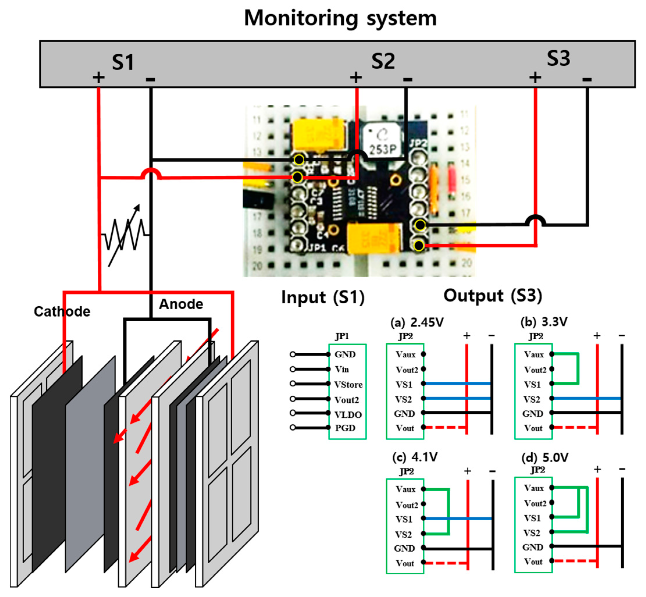
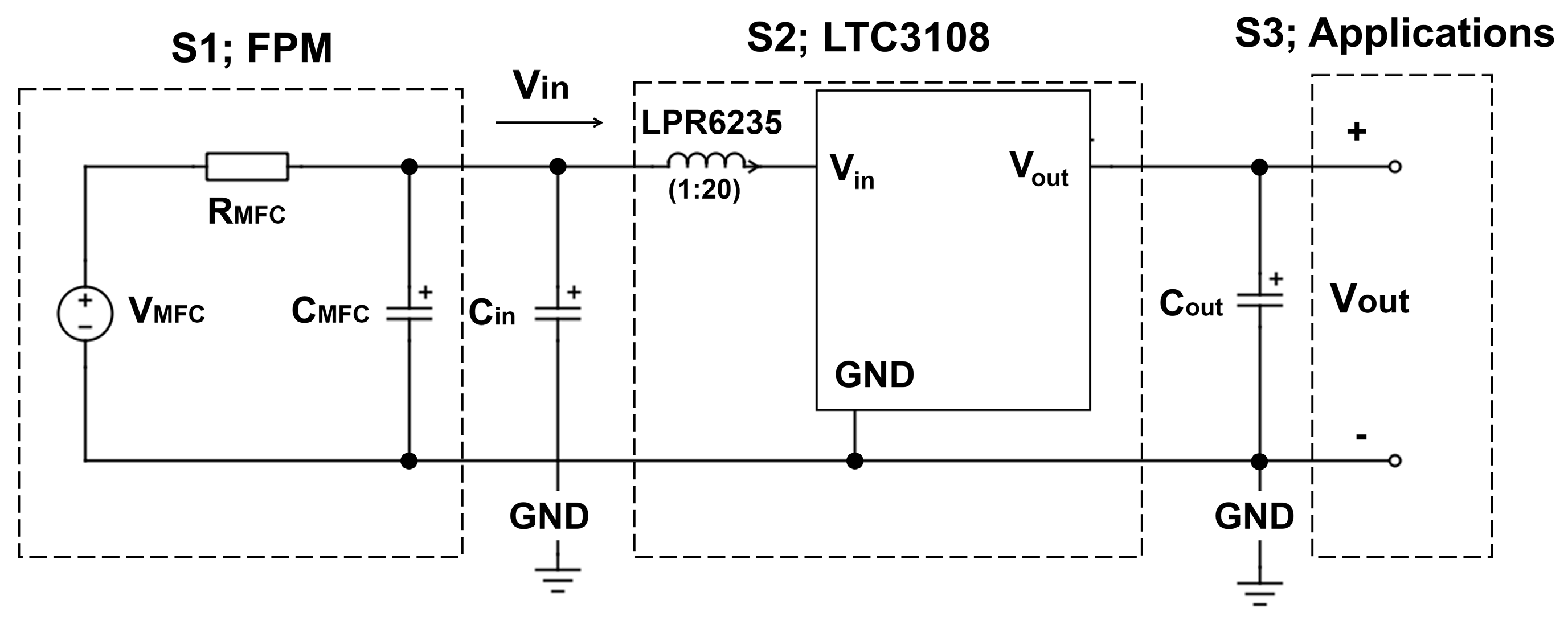
4.2. Specification of DC-DC Boost Converter Circuit

The DC-DC boost converter (Figure 8) was constructed to include energy harvester breakout (Crispytronics, San Diego, CA, USA). The components of the DC-DC boost converter included a small step-up transformer (LTC3108, Linear Technology, Silicon Valley, CA, USA), an inductor (LPR6235-253P Coilcraft, Cary, IL, USA), and capacitors. An N-Channel MOSFET (NMOS) switch was used to realize a resonance step-up oscillator with a transformer to boost the low input voltage from the FPM [18]. The minimum voltage and conversion efficiency of the boosting is determined by the turn ratio of the inductor. The specification of the LPR6235-752SML indicated that it can utilize a start-up voltage as low as 20 mV at 1:100 ratios. The transformer (LTC3108) had a maximum peak efficiency of approximately 60% with an input voltage as low as 100 mV using LPR6235-253PML. Therefore, it can be applied to typical MFC systems, which generate low voltage outputs, with an OCV typically below 0.6 V. The LTC3108 has internal rectifiers that support the current into the VAUX pin, providing charge to the external VAUX capacitor and outputs.
The main output voltage (Vout) is charged from the VAUX supply, and is controlled “manually” for the four regulated output voltages (i.e., boosted output voltages) using the signal combination on the specific pins (VS1 and VS2) (Figure 8). For example, when VS1 and VS2 are linked to the GND (ground) and Vout, respectively, the circuit converts the input voltage to the lowest output of 2.35 V. On the other hand, the highest voltage output of 5.0 V is achieved when VS1 and VS2 are connected to VAUX. Alternatively, when VS1 and VS2 are connected to VAUX/GND and GND/VAUX, voltages of 3.3 and 4.1 V, respectively, are achieved. In this study, two output voltages of 3.3 and 5.0 V were selected and tested using the DC-DC boost converter described.

4.3. DC-DC Boost Converter Operation with FPM

Figure 2 presents an overview of the boost converter system. The DC-DC booster system was connected to the FPM and assessed for its ability to improve the voltage output. The source voltage produced by the FPM acted as the DC-DC boost circuit input with three connection points for in situ monitoring of the voltage changes; S1 represents the source voltage from FPM; S2 is the DC-DC booster input voltage that can be drained by the circuit; S3 is the output voltage from the DC-DC booster (Figure 2). To monitor the data simultaneously, the FPM and each sampling point were logged with LabVIEW™ (National Instruments™, Austin, TX, USA) and NI-DAQ USB-6218 with a 16-bit resolution, input impedance >10 GΩ when in parallel with 100 pF and working over a ± 5 V range (National Instruments™, Austin, TX, USA).
The voltages at different connection points (S1, S2, and S3) were investigated and compared to determine the effects of the DC-DC booster system and its efficiency. In addition, voltage should be stepped-up with relatively high efficiency (i.e., low power loss) by the DC-DC boost converter. The boost efficiency was estimated using Equation (1) as follows:
Efficiency   ( η , % ) = P out P in × 100 =   I out × V out I in × V in × 100
where Vout and Iout are the output boosted voltage and current, Vin and Iin are the input source voltage and current from the FPM.

4.4. Analyses

Polarization tests were carried out by allowing the cell potential to stabilize after changes in the external load resistance from 50 kΩ to 1 Ω, using a resistance box (ZX21 Precision, Tlegend Instrument®, Shenzhen, China), while measuring the potential difference between the anode and cathode. Sampling was conducted at two points on the circuit (output voltage of FPM, S1, and DC-DC boost circuit, S3) using both the LabVIEW™ virtual instrumentation and a multi-meter (Fluke 17B, Everett, WA, USA). The sampled data were recorded continuously at 30 s intervals using LabVIEW™. After altering the load resistance, the FPM was allowed to stabilize for 10 min before applying the next load control. The COD was measured using a test kit (HUMAS Co. Ltd., Daejeon, Korea) by UV/Vis spectrophotometer (OPTIZEN POP, MECASYS Co. Ltd., Daejeon, Korea). The domestic wastewater and synthetic wastewater contained 101 ± 15 ppm and 1746 ± 136 ppm COD, respectively. To investigate the applicability of the boosted power from the FPM, several practical applications were tested, such as a low power demand mechanical clock movement (1.92 mW, DELI 1288, Shenzhen, China), a LED lamp (80 mW, BL-B3141-AA-AV, Seoul, Korea), and a micro DC motor (80 mW, MDN-4RA3FTAS, Matsushita, Japan).

5. Conclusions

An ultra-low voltage DC-DC booster converter system was developed and applied to a continuously operated flat-plate MFC system utilizing domestic and synthetic wastewater. This boost converter could step-up the voltage from the MFC in the region of ~0.5 V to an output voltage of 3.3 and/or 5.0 V, which is suitable for practical applications. The FPM voltage is interrelated with the DC-DC booster and adapts dynamically to the booster set point that is designated by the circuit. The output maximum power density of the MFC with a DC-DC booster circuit was 8.16 W/m3 compared to the FPM (14.27 W/m3). This represents a power conversion efficiency of 26–57%, which is a higher conversion efficiency than previous reports. The combined system can operate several low power demand electronic devices, such as a micro DC motor, an LED lamp, and a mechanical clock movement powered by wastewater. The MFC-customized DC-DC boosters developed in this study will maximize the energy recovery from wastewater, and help to expand the field of applications of MFC systems.

Acknowledgments

This study was supported financially by the MFC Research and Business Development (R&BD) center co-funded with K-water, Hanhwa E&C, and Taeyoung E&C; Mid-career Researcher Program (2013069183) through the National Research Foundation of Korea (NRF); and also supported by the NERC RRfW METEORR project (NE/L0 14106/1).

Author Contributions

This paper was prepared by collaboration of authors affiliated in different institutes. Young Eun Song conducted experiments and wrote the manuscript. Hitesh C. Boghani and Giuliano C. Premier provided the idea of PMS and edited the manuscript. Hong Suck Kim, Byung Goon Kim, and Taeho Lee provided the microbial fuel cell reactors and financially support the work. Byong-Hun Jeon provided valuable comments and editing for the manuscript. Jung Rae Kim led the experimental work and manuscript preparation as corresponding author.

Conflicts of Interest

The authors declare no conflict of interest for personal circumstances and financial support as we stated in the cover letter.

References

  1. Cheng, S.; Liu, H.; Logan, B.E. Increased performance of single-chamber microbial fuel cells using an improved cathode structure. Electrochem. Commun. 2006, 8, 489–494. [Google Scholar] [CrossRef]
  2. Wang, Y.-H.; Wang, B.-S.; Pan, B.; Chen, Q.-Y.; Yan, W. Electricity production from a bio-electrochemical cell for silver recovery in alkaline media. Appl. Energy 2013, 112, 1337–1341. [Google Scholar] [CrossRef]
  3. Rabaey, K.; Verstraete, W. Microbial fuel cells: Novel biotechnology for energy generation. Trends Biotechnol. 2005, 23, 291–298. [Google Scholar] [CrossRef] [PubMed]
  4. Premier, G.C.; Kim, J.R.; Michie, I.; Dinsdale, R.M.; Guwy, A.J. Automatic control of load increases power and efficiency in a microbial fuel cell. J. Power Sources 2011, 196, 2013–2019. [Google Scholar] [CrossRef]
  5. Shin, S.H.; Choi, Y.J.; Na, S.H.; Jung, S.H.; Kim, S. Development of bipolar plate stack type microbial fuel cells. Bull. Korean Chem. Soc. 2006, 27, 281–285. [Google Scholar]
  6. Aelterman, P.; Rabaey, K.; Pham, H.T.; Boon, N.; Verstraete, W. Continuous electricity generation at high voltages and currents using stacked microbial fuel cells. Environ. Sci. Technol. 2006, 40, 3388–3394. [Google Scholar] [CrossRef] [PubMed]
  7. Oh, S.E.; Logan, B.E. Voltage reversal during microbial fuel cell stack operation. J. Power Sources 2007, 167, 11–17. [Google Scholar] [CrossRef]
  8. Ieropoulos, I.; Melhuish, C.; Greenman, J.; Horsfield, I. EcoBot-II: An artificial agent with a natural metabolism. J. Adv. Rob. Syst. 2005, 2, 295–300. [Google Scholar] [CrossRef]
  9. Papaharalabos, G.; Greenman, J.; Stinchcombe, A.; Horsfield, I.; Melhuish, C.; Ieropoulos, I. Dynamic electrical reconfiguration for improved capacitor charging in microbial fuel cell stacks. J. Power Sources 2014, 272, 34–38. [Google Scholar] [CrossRef]
  10. Donovan, C.; Dewan, A.; Peng, H.; Heo, D.; Beyenal, H. Power management system for a 2.5 W remote sensor powered by a sediment microbial fuel cell. J. Power Sources 2011, 196, 1171–1177. [Google Scholar] [CrossRef]
  11. Meehan, A.; Gao, H.; Lewandowski, Z. Energy harvesting with microbial fuel cell and power management system. IEEE Trans. Power Electron. 2011, 26, 176–181. [Google Scholar] [CrossRef]
  12. Erickson, R.W. DC-DC Power Converters. In Wiley Encyclopedia of Electrical and Electronics Engineering; John Wiley & Sons, Inc.: Hoboken, NJ, USA, 2001. [Google Scholar]
  13. Wu, P.K.; Biffinger, J.C.; Fitzgerald, L.A.; Ringeisen, B.R. A low power DC/DC booster circuit designed for microbial fuel cells. Process Biochem. 2012, 47, 1620–1626. [Google Scholar] [CrossRef]
  14. Park, J.-D.; Ren, Z. High efficiency energy harvesting from microbial fuel cells using a synchronous boost converter. J. Power Sources 2012, 208, 322–327. [Google Scholar] [CrossRef]
  15. Adami, S.E.; Degrenne, N.; Vollaire, C.; Allard, B.; Buret, F.; Costa, F. Autonomous Ultra-Low Power DC/DC Converter for Microbial Fuel Cells. In Proceedings of the 2011 18th IEEE International Conference on Electronics, Circuits and Systems (ICECS 2011), Beirut, Lebanon, 11–14 December 2011; pp. 398–401. [Google Scholar]
  16. Wang, H.; Park, J.-D.; Ren, Z.J. Practical energy harvesting for microbial fuel cells: A review. Environ. Sci. Technol. 2015, 49, 3267–3277. [Google Scholar] [CrossRef] [PubMed]
  17. Yang, F.; Zhang, D.; Shimotori, T.; Wang, K.-C.; Huang, Y. Study of transformer-based power management system and its performance optimization for microbial fuel cells. J. Power Sources 2012, 205, 86–92. [Google Scholar] [CrossRef]
  18. Pathirana, W.; Muhtaroglu, A. Low Voltage DC-DC Conversion without Magnetic Components for Energy Harvesting. In Proceedings of the 2012 International Conference on Energy Aware Computing, Guzelyurt, Cyprus, 3–5 December 2012; pp. 1–6. [Google Scholar]
  19. Zhang, D.; Yang, F.; Shimotori, T.; Wang, K.-C.; Huang, Y. Performance evaluation of power management systems in microbial fuel cell-based energy harvesting applications for driving small electronic devices. J. Power Sources 2012, 217, 65–71. [Google Scholar] [CrossRef]
  20. Boghani, H.C.; Kim, J.R.; Dinsdale, R.M.; Guwy, A.J.; Premier, G.C. Control of power sourced from a microbial fuel cell reduces its start-up time and increases bioelectrochemical activity. Bioresour. Technol. 2013, 140, 277–285. [Google Scholar] [CrossRef] [PubMed]
  21. Donovan, C.; Dewan, A.; Heo, D.; Beyenal, H. Batteryless, wireless sensor powered by a sediment microbial fuel cell. Environ. Sci. Technol. 2008, 42, 8591–8596. [Google Scholar] [CrossRef] [PubMed]
  22. Kim, Y.; Hatzell, M.C.; Hutchinson, A.J.; Logan, B.E. Capturing power at higher voltages from arrays of microbial fuel cells without voltage reversal. Energy Environ. Sci. 2011, 4, 4662–4667. [Google Scholar] [CrossRef]
  23. Park, J.-D.; Ren, Z. Efficient Energy Harvester for Microbial Fuel Cells using DC/DC Converters. In Proceedings of the 2011 IEEE Energy Conversion Congress and Exposition (ECCE 2011), Phoenix, AZ, USA, 17–22 September 2011; pp. 3852–3858. [Google Scholar]
  24. Degrenne, N.; Buret, F.; Morel, F.; Adami, S.E.; Labrousse, D.; Allard, B.; Zaoui, A. Self-Starting DC:DC Boost Converter for Low-Power and Low-Voltage Microbial Electric Generators. In Proceedings of the 2011 IEEE Energy Conversion Congress and Exposition (ECCE 2011), Phoenix, AZ, USA, 17–22 September 2011; pp. 889–896. [Google Scholar]
  25. Gao, H.; Meehan, A.; Lewandowski, Z. New Microbial Fuel Cell Power System for Efficiency Improvement. In Proceedings of the 2011 International Conference on Electrical Machines and Systems (ICEMS 2011), Beijing, China, 20–23 August 2011; pp. 1–5. [Google Scholar]
  26. Donovan, C.; Dewan, A.; Heo, D.; Lewandowski, Z.; Beyenal, H. Sediment microbial fuel cell powering a submersible ultrasonic receiver: New approach to remote monitoring. J. Power Sources 2013, 233, 79–85. [Google Scholar] [CrossRef]
  27. Thomas, Y.R.; Picot, M.; Carer, A.; Berder, O.; Sentieys, O.; Barrière, F. A single sediment—Microbial fuel cell powering a wireless telecommunication system. J. Power Sources 2013, 241, 703–708. [Google Scholar] [CrossRef]
  28. Karra, U.; Muto, E.; Umaz, R.; Kölln, M.; Santoro, C.; Wang, L.; Li, B. Performance evaluation of activated carbon-based electrodes with novel power management system for long-term benthic microbial fuel cells. Int. J. Hydrogen Energy 2014, 39, 21847–21856. [Google Scholar] [CrossRef]
  29. Ewing, T.; Ha, P.T.; Babauta, J.T.; Tang, N.T.; Heo, D.; Beyenal, H. Scale-up of sediment microbial fuel cells. J. Power Sources 2014, 272, 311–319. [Google Scholar] [CrossRef]
  30. Alaraj, M.; Ren, Z.J.; Park, J.-D. Microbial fuel cell energy harvesting using synchronous flyback converter. J. Power Sources 2014, 247, 636–642. [Google Scholar] [CrossRef]
  31. Xu, Z.; Hao, R.; Soonjae, P.; Jae-Ik, L.; Jongbaeg, K.; Junseok, C. A high-efficiency DC-DC boost converter for a miniaturized microbial fuel cell. IEEE Trans. Power Electron. 2015, 30, 2041–2049. [Google Scholar]
  32. Carreon-Bautista, S.; Erbay, C.; Han, A.; Sanchez-Sinencio, E. Power management system with integrated maximum power extraction algorithm for microbial fuel cells. IEEE Trans. Energy Convers. 2015, 30, 262–272. [Google Scholar] [CrossRef]
  33. Fradler, K.R.; Kim, J.R.; Boghani, H.C.; Dinsdale, R.M.; Guwy, A.J.; Premier, G.C. The effect of internal capacitance on power quality and energy efficiency in a tubular microbial fuel cell. Process Biochem. 2014, 49, 973–980. [Google Scholar] [CrossRef]
  34. Sevda, S.; Dominguez-Benetton, X.; Vanbroekhoven, K.; De Wever, H.; Sreekrishnan, T.; Pant, D. High strength wastewater treatment accompanied by power generation using air cathode microbial fuel cell. Appl. Energy 2013, 105, 194–206. [Google Scholar] [CrossRef]
  35. Yu, J.; Park, Y.; Lee, T. Effect of separator and inoculum type on electricity generation and microbial community in single-chamber microbial fuel cells. Bioprocess Biosyst. Eng. 2014, 37, 667–675. [Google Scholar] [CrossRef] [PubMed]
  36. Cheng, S.; Liu, H.; Logan, B.E. Increased power generation in a continuous flow MFC with advective flow through the porous anode and reduced electrode spacing. Environ. Sci. Technol. 2006, 40, 2426–2432. [Google Scholar] [CrossRef] [PubMed]
Figure 1. (a) Enrichment voltage development of a flat-plate MFC; and (b) polarization curve for flat-plate MFC.
Energies 10 00596 g001
Figure 2. Topology of a DC-DC converter with a MFC for various applications. S1: source voltage from a flat-plate MFC (MFC source voltage); S2: Input voltage to DC-DC boost converter; and S3: output voltage for application. MFC: microbial fuel cell; FPM: flat-plate MFC; and GND: ground.
Energies 10 00596 g002
Figure 3. Effect of the variation of the load resistances (categorized into lower and higher shown in the legend) to operate a boost circuit with a FPM; source voltage generated from FPM with different load resistances (S1, a & d), DC-DC booster input voltage (S2, b & e), output boosted voltage from the DC-DC boost converter by different load resistances (S3, c & f).
Energies 10 00596 g003aEnergies 10 00596 g003b
Figure 4. Voltage variations through the FPM DC-DC boost converter circuit using different wastewater; comparison of the source voltage generation and boosted voltage for short term operation (S1, a & c), and source voltage generation and boosted voltage for a longer term operation with a DC-DC circuit converter (S3, b & d).
Energies 10 00596 g004
Figure 5. Maximum power density and voltage generation of the FPM according to external load resistance estimated through linear sweep voltammetry.
Energies 10 00596 g005
Figure 6. Polarization curve of the boosted flat-plate MFC; (a) 3.3 V and (b) 5.0 V setting on closed circuit voltage (CCV) (100 Ω); (c) 3.3 V and (d) 5.0 V setting on open circuit voltages (OCV).
Energies 10 00596 g006
Figure 7. Power conversion efficiencies for the CCV and OCV operation with a set voltage of 3.3 and 5.0 V.
Energies 10 00596 g007
Figure 8. Overview of the DC-DC boosting system and connection to a flat-plate MFC.
Energies 10 00596 g008
Table 1. Comparison of the boosting efficiencies of FPM in CCV and OCV as compared to non-boosting condition by DC/DC booster.
OperationFlat-Plate MFC (w/o Boosting)CCV aOCV b
Voltage output (V)0.63.35.03.35.0
Power (mW)2.860.951.220.520.56
Power density (W/m3)14.276.348.163.473.74
Efficiency (η, %)44.4357.1427.8226.21
a CCV: closed circuit voltage operation that employed an external resistance on the source FPM reactor; b OCV: open circuit voltage operation that did not employ an external resistance, and was directly connect to the DC-DC booster.
Table 2. Practical applications of the DC-DC booster circuit to operate low power demand electronics with synthetic and domestic wastewater.
Case 1: Synthetic Wastewater
Clock Movement (1.9 mW)LED Lamp (80 mW)Micro DC Motor (80 mW)
Short Term *Long Term *Short Term *Long Term *Short Term *Long Term *
FPMSingle (0.6 V)
Dual (1.1 V)++
Boosted FPM **Boosted to 3.3 V+++
Boosted to 5.0 V+++++
Case 2: Domestic Wastewater
Clock Movement (1.9 mW)LED Lamp (80 mW)Micro DC Motor (80 mW)
Short Term *Long Term *Short Term *Long Term *Short Term *Long Term *
FPMSingle (0.6 V)
Dual (1.1 V)+
Boosted FPM **Boosted to 3.3 V+++
Boosted to 5.0 V++++
* Short term: ~1 min; Long term: over 30 min; +: able; −: unable; ** The DC-DC booster was applied to a single FPM.
Table 3. Comparison of the performances of power management systems for MFC.
MFC TypeVolumeOperational ModeSubstrateAnodeCathodeInputOutputConverting EfficiencyMaximum PowerReferences
SedimentN/AN/ARiver water (MnO2)Graphite plateStainless steel wire (1.2 m2)0.4 V3.3 V73% at 0.88 V0.12 mW[21]
Cubic inner cylindrical chamber27 mLFed-BatchAcetateCarbon brushesCarbon paper (pt)0.7 V2.5 V92.3% at 0.85 V (with 4 cell)0.78 mW[22]
Lab scale Two-chamber48 mLBatchAcetateCarbon paperCarbon cloth0.328 V3.3 VN/A1.2 mW[23]
Single chamber1 LBatchDomestic wastewaterGraphite fiber brushCarbon paper0.3 V2.7 V74% at 0.3 V540 μW[24]
SedimentN/AN/ARiver waterGraphite PlateGraphite0.395 V5 V80.6% at 4.07 V (Vin = 0.395 V)24.32 mW[10]
Sediment1.01 LN/ALactateGraphite plateCarbon bend0.7 V3.3 V79% at 1.8 V (Vin = 0.7 V)> 21 mW[25]
Sediment (open water system)1.01 LN/ALactateGraphite plateCarbon bend0.7 V3.3 V87% at 1.8 V (Vin = 0.7 V)1 mW[11]
Single chamber0.9 LBatchAcetateCarbon fiber brushCarbon paper0.475 V2–7.5 V60.2% at 0.475 V113 μW[15]
Two-chamber (cubic)140 mLBatchAcetateHeated graphite brushesCarbon paper0.315 V2.5 V73% at 0.315 V378 μW[14]
SedimentN/AN/ARiver waterGraphite plateGraphite plate0.52 V3.6 V75.3% at 0.52 V10.7 mW[26]
Sediment0.8 LBatchAcetateGraphite granulesCarbon felt disc0.193 V3.3 V53% at 0.193 V2.5 mW[27]
Underwater benthic500 mLBatchAcetateCarbon fiber brushCarbon paper0.6 V3.3 V22.45% at 0.6 V0.56 W/m2[28]
Sediment240 LBatchRiver waterGraphite feltGraphite felt~0.8 V2.7 V59.5% at 0.8 V (output current: 2 mA)0.68 mW[29]
Two-chamber (cubic)150 mLBatchAcetateGraphite brushesCarbon cloth0.3 V2.13 V50.3% after 25 min3.21 mW[30]
Miniaturized MFC50 μLBatchAcetateVertically aligned carbon nanotubeCr/Au>0.6 V0.9–1.2 V85% at 0.9 V10 μW[31]
Two-chamber240 mLBatchAcetateCarbon feltCarbon cloth0.72 V2.5 V58% at 0.72 V320 μW[32]
Flat-plat MFC150 mLContinuousAcetate and domestic wastewaterCarbon feltCarbon cloth~0.7 V5.0 V57.17% at 0.46 V2.86 mWThis study

