Article

Performance Evaluation of Waste Heat Recovery Systems Based on Semiconductor Thermoelectric Generators for Hypersonic Vehicles

Harbin Institute of Technology, No. 92, West Da-Zhi Street, Harbin 150001, China
*
Author to whom correspondence should be addressed.
Energies 2017, 10(4), 570; https://doi.org/10.3390/en10040570
Submission received: 15 February 2017 / Revised: 28 March 2017 / Accepted: 4 April 2017 / Published: 22 April 2017
(This article belongs to the Section F: Electrical Engineering)

Abstract

:
The types and the characteristics of the waste heat on hypersonic vehicles and the application feasibility of thermoelectric generators (TEGs) for hypersonic aircraft are discussed in this paper. Two thermoelectric generator schemes with an isothermal heat source and a variable temperature heat source were proposed, and the corresponding models were developed to predict the performance of the waste heat recovery systems on a hypersonic vehicle with different heat sources. The thermoelectric efficiency variation with electric current, the temperature distribution of fuel and junctions, and the distribution of the thermoelectric figure of merit (ZT value) are described by diagrams. Besides, some improvements for a better performance are analyzed. The results indicate that the maximum values of thermoelectric efficiency are 5% and 2.5% for the isothermal heat source and the variable temperature heat source, respectively, and the thermoelectric efficiency improves with the temperature of the hot junction. The performance of the TEGs with variable temperature heat source is worse than that of the other TEGs under the same highest hot junction temperature conditions, and the former has a better conversion efficiency than the latter when the average temperatures are identical.

1. Introduction

Hypersonic flight vehicles are a novel type of aircraft in the fields of aeronautics and astronautics for hypersonic missions, such as the surveillance missions, military strikes and space transportation [1]. In a surveillance mission, the efficiency and flexibility of the hypersonic flight vehicles are higher than those of reconnaissance satellites, and the response speed of hypersonic aircraft will be higher than that of existing unmanned reconnaissance aircraft. In military strike missions, the high speed of hypersonic flight vehicles can reduce the response time of military defense systems and the flight time from base to target, so they are suitable for attacking rapidly maneuvering targets. In space transportation missions, the cost of the hypersonic flight vehicle will be lower for a higher payload and it allows repeated use, compared with presently used rockets.
The waste heat on a hypersonic vehicle is any heat source that is not utilized effectively, such as the aerodynamic heat and the heat dissipated on engine walls. The total temperature of the inlet airflow caused by the hypersonic flight in a hypersonic vehicle is extremely high. The steady-state temperature of the leading edge can reach almost 1927 °C (2200 K) and the temperatures of the other parts are about 1093 °C (1366 K), for a Mach number of 8 [2]. Besides, the wall temperature and the wall heat flux of the propulsion system, which may be a scramjet [3] or combined cycle engines, like the Turbine Based Combined Cycle (TBCC) [4] and the Rocket Based Combined Cycle (RBCC) [5], are also extremely high. Hence, these high temperatures are a technical challenge for hypersonic flight from the point of thermal protection, but the high temperature and the high heat flux can also be treated as the heat source for an electricity generation system. Heat sources with different temperatures, namely different energy levels [6], can be utilized to generate electricity through different thermodynamic cycles, or other thermoelectric conversion technologies, such as the use of semiconductor thermoelectric generators (TEGs).
Waste heat recovery is already an important means to improve the efficiency of powertrains, especially for road vehicles [7]. Some methods, such as Organic Rankine Cycle (ORC) system [8], turbochargers [9], turbocompounding [10], chemical recuperation [11], cabin cooling [12] and in-cylinder waste heat recovery [13], have been investigated and utilized to realize the recovery of waste heat for motor vehicles. Thermoelectric generators, also called as thermoelectric devices (TEDs), which can convert thermal energy into electricity directly using the Seebeck effect [14], have also been developed for waste heat recovery in internal combustion engines [15]. Compared with the present thermodynamic cycles, thermoelectric generators with a simpler structure, less vibration and a higher reliability profiting from no rotating parts [16], are more suitable for waste heat recovery on a vehicle.
Some studies on waste heat recovery for automobiles using thermoelectric generators have been published. Bass et al. [17,18] from Hi-Z Technology, Inc. (San Diego, CA, USA) developed a 1 kW thermoelectric generator by converting part of the waste heat in the engine’s exhaust directly into electricity for class eight diesel truck engines to replace the shaft-driven alternator, and predicted that a reduction in fuel consumption between 12% and 30% would be achieved if the 1 kW TEG unit were replaced by multilayer film materials with 20% efficiency. The proposed thermoelectric generator comprised of 72 thermoelectric modules (TEMs), could produce 1 kW of electrical power at 30 V DC during the nominal engine operation of a heavy duty class eight diesel trucks, and the figures of merit Z of the films were 9 × 10⁻³ 1/°C and 27 × 10−3 1/°C, respectively, based on bulk and quantum well thermoelectric materials. Matsubara [19] developed a high efficiency thermoelectric stack, which consisted of thermoelectric modules and a heat exchanger, for application in electrical power generation for vehicles. The experimental data obtained in the 350–750 °C temperature range showed the validity of installing a thermoelectric stack in vehicles and the problems in practical application, and a 10% improvement of vehicle fuel economy would be realized with an overall conversion efficiency of 5–10%.
Yang [20] reviewed several applications of thermoelectric waste heat recovery devices in the automotive industry and investigated the effect of electrical load and weight on fuel economy to assess the feasibility of applications at a vehicle level. The results showed that the key of the realization was the continued development of new materials with increased thermoelectric efficiency. LaGrandeur et al. [21] created a system architecture for a high efficiency thermoelectric waste energy recovery system for passenger vehicles, and developed a system model to predict its performance. The results presented the status of the system architecture, modeling and key technologies and provided a performance prediction. Saqr et al. [22] described the construction of a typical exhaust-based thermoelectric generator, and discussed the heat balance and efficiency of exhaust-based thermoelectric generators. The main objectives and challenges for designing efficient exhaust-based thermoelectric generator systems were also emphasized.
Advanced thermoelectric materials are the key to improve the conversion efficiency of TEGs [23], and some remarkable progress in improving thermoelectric properties have been made, due to the recently gained ability to create nanostructured materials, such as superlattices [24], quantum dots [25], nanowires [26] and nanocomposites [27]. Heremans et al. [28] explored enhancing the Seebeck coefficient through a distortion of the electronic density of states, and improved the thermoelectric figure of merit (ZT value) in P-type PbTe to above 1.5 at 773 K, through the manipulation of the thallium impurity levels in lead telluride. Pei et al. [29] studied the electrical and thermal transport properties of lead-based chalcogenides, and the power factors at room temperature for PbS, PbSe and PbTe could reach 12 μWcm−1K−2, 14 μWcm−1K−2 and 16 μWcm−1K−2, respectively. Jiang et al. [30] examined the anisotropy of the p-type SiGe single crystals with <111> and <100> orientation which were grown by the Czochralski method, and measured the Seebeck coefficient in the temperature range of 300–900 K. The results indicated that the Seebeck coefficient of the sample with <111> orientation was around 325–400 μV/K, while that of the sample with <100> orientation was about 450–530 μV/K.
In this paper, the types and the characteristics of the waste heat on the hypersonic flight vehicles will be discussed, and thermoelectric generator models based on an isothermal heat source and a variable temperature heat source are developed to predict the performance of the waste heat recovery systems on a hypersonic flight vehicle. The thermoelectric efficiency variation with electric current, the temperature distribution of fuel and junctions, and the distribution of the thermoelectric figure of merit for both models will be described in diagrams using calculation results. Besides, a comparison between different heat sources will be made, and the shortcomings of different models will be also discussed briefly.

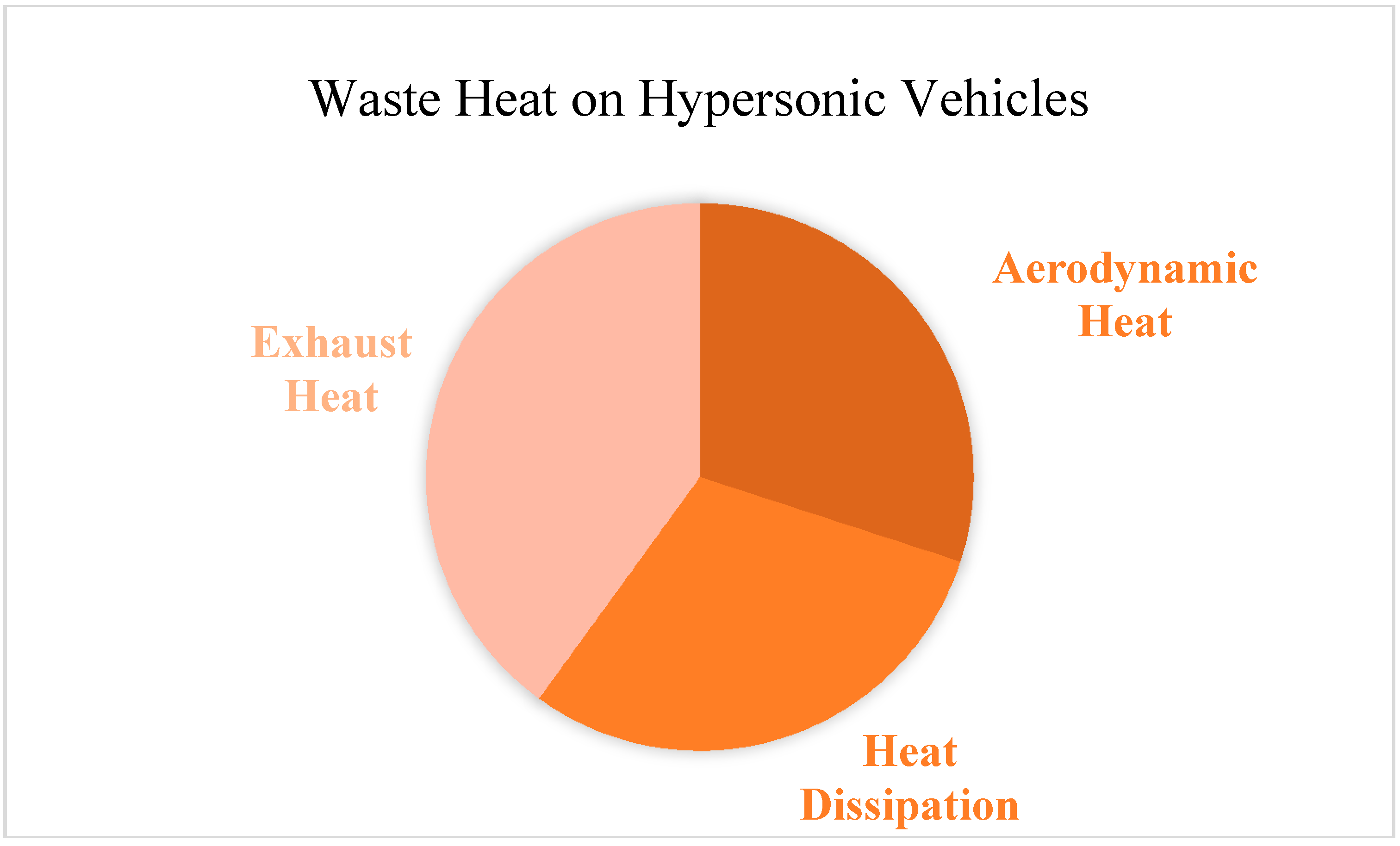
2. Analysis of Waste Heat on a Hypersonic Vehicle
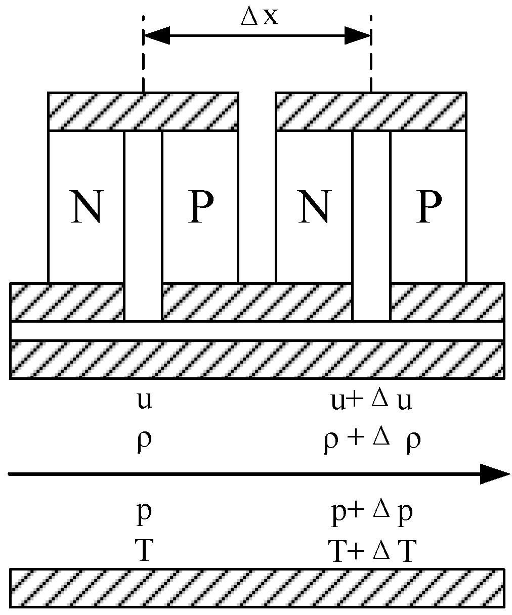
The waste heat on a hypersonic flight vehicle is quite different from that of a ground power system like a motor vehicle in types and energy levels. There are mainly three types of waste heat on a hypersonic flight vehicle, namely, the aerodynamic heat produced by the viscous effects between aircraft skin and air flow, the heat dissipation from flame to engine walls in combustor and nozzle, and the exhaust heat not utilized in the expansion process, as shown in Figure 1. Other types of waste heat, such as the heat dissipation in electronic components will not be discussed in this paper, because the heat exergy of a heat source with a low temperature is too small to be utilized efficiently.
Aerodynamic heat caused by the friction between the hypersonic airflow and the aircraft skin, is treated as a kind of waste heat because it is always regarded as a technology challenge for thermal protection rather than an effective heat source to be utilized for electricity generation. The temperature and the heat flux of aerodynamic heat, especially on the nose and the leading edge of aircraft, are quite high when a hypersonic vehicle flights travels at a high Mach number within the atmosphere. Reference [31] indicates that the maximum outer surface temperature expected at the component location is between 816 °C (1089 K) and 899 °C (1172 K). It means that passive thermal protection technologies based on high-temperature resistant materials can hardly meet the needs of thermal protection during a long duration flight, and some kind of active cooling system is necessary to protect the airframe from damage caused by the aerodynamic heat. Hence, it is possible to apply thermoelectric generators for electricity generation using the aerodynamic heat and the coolant of the active thermal protection system.
The heat dissipation on the engine walls is another kind of waste heat for a hypersonic flight vehicle if the heat dissipation cannot be utilized effectively. Strictly speaking, for a regeneratively cooled scramjet [32], one of the most promising propulsion systems for hypersonic flight, the heat dissipated on engine walls is carried back into the combustor by the coolant, namely the high temperature fuel, and cannot be regarded as waste heat. However, it is a better use pattern to convert heat into electricity or shaft work first and then transfer the remaining heat into the combustor from the point of view of energy utilization [33]. Therefore, the heat dissipation on engine walls is applied as an important kind of heat source for thermoelectric devices in this paper.
Due to the big temperature difference between the flame and engine wall, the amount of the heat dissipation on the engine walls is very large, and can reach 5–10% of the total heat release of the fuel combustion in the combustor [34]. Compared with the heat dissipation for automotive engines, the energy level of the heat dissipation on the engine walls for a hypersonic flight vehicle is quite high because the operation temperature of the coolant for a regenerative cooling system is much higher than that of the cooling water for automotive engines. The maximum temperature for the endothermic hydrocarbon fuel can reach about 1000 K without coking and carbonization [35], so it is possible to create a thermoelectric device using the cold fuel and the hot fuel heated by heat dissipation.
Like automotive engines, the exhaust heat of the propulsion system is a sort of main waste heat in hypersonic flight vehicles. The exhaust temperature is usually extremely high (1163 K) under a high fuel equivalence ratio (0.76) and a finite cycle pressure ratio (51.95), which means that there is still a large amount of heat exergy in the exhaust gas [36]. However, unlike land-based power systems, the regenerators used as the waste heat recovery component on the ground can be hardly utilized on an aircraft because of their weight and aerodynamic drag. Hence, at present it is difficult to directly take advantage of the exhaust heat available on hypersonic flight vehicles.

3. Models

3.1. Basic Principles of TEGs

Thermoelectric generators converting thermal energy into electricity directly are based on the Seebeck effect, which predicts that there will be current and voltage in a closed circuit comprised by different conductive materials, if the junction temperatures are different. For a better understanding of the models used in this work, some fundamental principles of the Seebeck effect and the zero-dimensional equations for a thermoelectric unicouple will be described as follows, according to [16,37]. The thermoelectric figure of merit, namely the ZT value, is usually used to measure the thermoelectric efficiency of thermoelectric materials. Z is defined as follows:
Z = α 2 σ λ
where α is the Seebeck coefficient defined by:
α = lim Δ T 0 Δ U Δ T = d U d T
The characteristic temperature is usually defined as the average temperature of the junction temperatures:
T = T h + T c 2
In this way, the thermoelectric figure of merit is dimensionless. According to the principles of electrotechnics and the Seebeck effect, the basic equations of a thermoelectric unicouple can be described as follows. The open-circuit voltage in the loop is the product of the Seebeck coefficient and the temperature difference between the hot junction and the cold junction:
U o = α ( T h T c )
The electric current of the circuit is:
I = U o R i n + R L = α ( T h T c ) R i n + R L
The internal resistance is:
R i n = l P σ P A P + l N σ N A N
The load voltage can be described as:
U L = R L R i n + R L U o = α ( T h T c ) R L R i n + R L
The electric power output of the thermoelectric unicouple is the product of the load voltage and the current in the circuit:
P = U L I = α 2 ( T h T c ) 2 R L ( R i n + R L ) 2
The Peltier heat of the hot junction and the cold junction with the current I can be expressed as follows, respectively:
Q h P = α I T h
Q c P = α I T c
The Joule heat caused by the internal resistance is:
Q J = I 2 R i n
According to Fourier’s heat conduction law, the conductive heat can be described as:
Q K = K ( T h T c )
The coefficient of thermal conduction K is:
K = λ P A P l P + λ N A N l N
According to the first law of thermodynamics, the heat transfer rates of the hot junction and the cold junction can be expressed as follows, respectively:
Q h = Q h P + Q K 0.5 Q J = α I T h + K ( T h T c ) 0.5 I 2 R i n
Q c = Q c P + Q K + 0.5 Q J = α I T c + K ( T h T c ) + 0.5 I 2 R i n
In this way, the thermoelectric efficiency of the thermoelectric unicouple can be defined as:
η = P Q h = α 2 ( T h T c ) 2 R L ( R i n + R L ) 2 [ α I T h + K ( T h T c ) 0.5 I 2 R i n ]

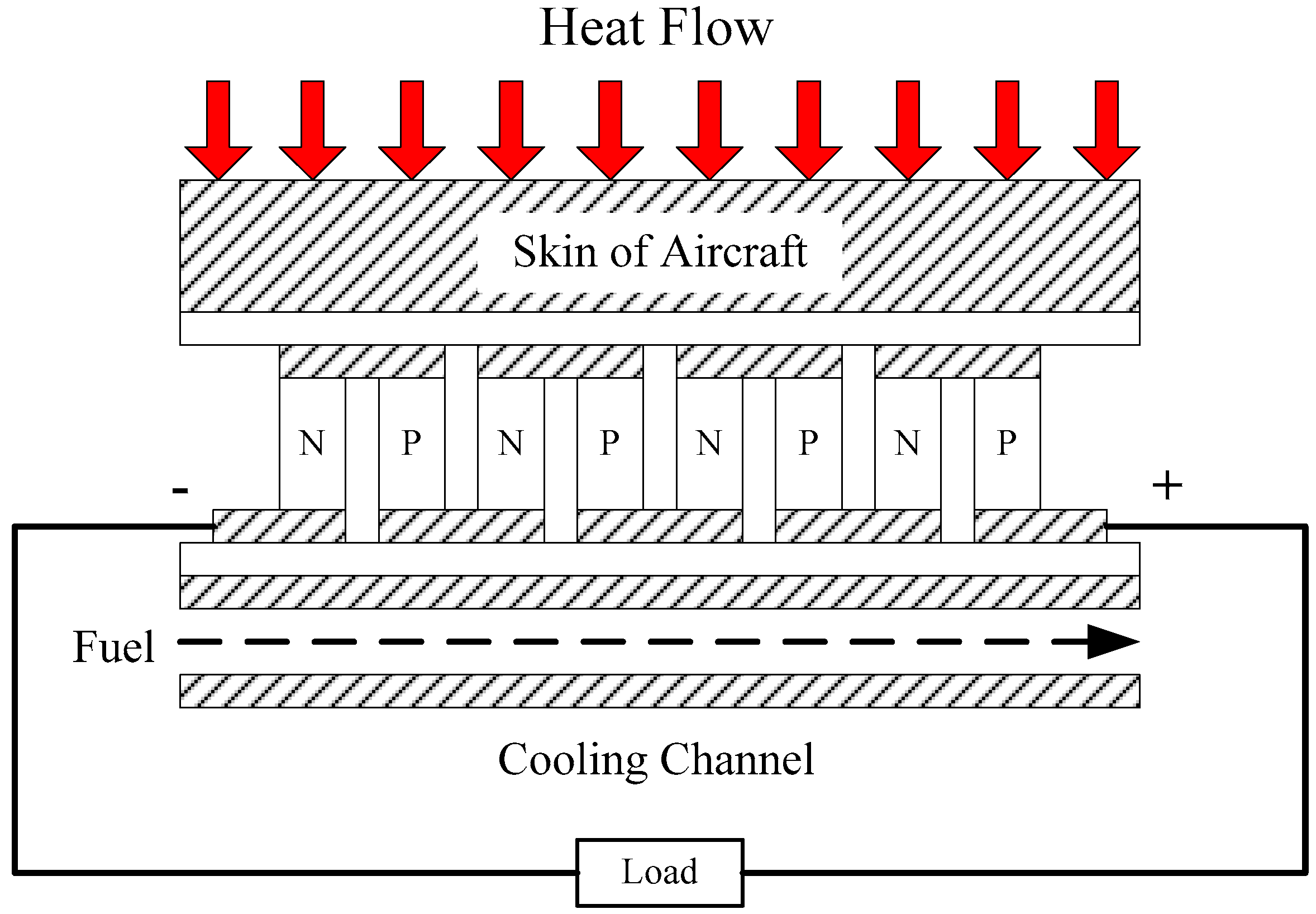
3.2. Isothermal Heat Source

Considering the heat transfer rate of a thermoelectric device is not high enough to influence a heat resource with a quite high heat flux, the temperature of some heat sources, such as the aerodynamic heat on the leading edges of aircraft, can be treated as a constant. A sketch of a thermoelectric generator with an isothermal heat source is shown in Figure 2. The heat source of the thermoelectric device is the aerodynamic heat coming through the skin of aircraft, and the cold source for the system is the fuel carried by the hypersonic flight vehicle, which is always treated as the only coolant for a hypersonic flight [38]. A number of thermoelectric couples located between the skin of the aircraft and the cooling channels are connected in series. The temperatures of the hot junctions can be kept as an approximately constant value because the influence of the thermoelectric device on the temperature distribution of skin is extremely small. To avoid the issue of thermal cracking of the endothermic hydrocarbon fuel, the fuel is set as hydrogen in this paper for convenience of calculation.
For the fuel in the cooling channels, the calculation model is shown in Figure 3, and the governing equations are as follows:
1 ρ f Δ ρ f Δ x + 1 u f Δ u f Δ x = 0
m ˙ Δ u f Δ x + A Δ p f Δ x + 1 2 f D h m ˙ u f = 0
m ˙ ( c p Δ T f c Δ x + u f Δ u f Δ x ) = Q c Δ x
1 p f Δ p f Δ x = 1 ρ f Δ ρ f Δ x + 1 T f c Δ T f c Δ x
where Equation (17) is the conservation of mass, Equation (18) is the conservation of momentum in the x direction, Equation (19) is the conservation of energy, and Equation (20) is the equation of state.
According to the principles of heat transfer, the heat transfer rate of the cold junction can also be expressed as:
Q c = h c A c ( T c T f c )
The Dittus-Boelter equation [39] is applied to predict the forced convection coefficient as follows:
h c = N u c λ f c D h
N u c = 0.023 Re c 0.8 Pr c 0.4
Combining Equations (15) and (21), the temperature of the cold junction will be expressed as:
T c = K T h + 0.5 I 2 R i n + h c A c T f c h c A c + K α I
In this way, the temperature of cold junction can be calculated from the temperature of the hot junction and fuel, the heat transfer coefficient on the channel walls and the electric current of the circuit.

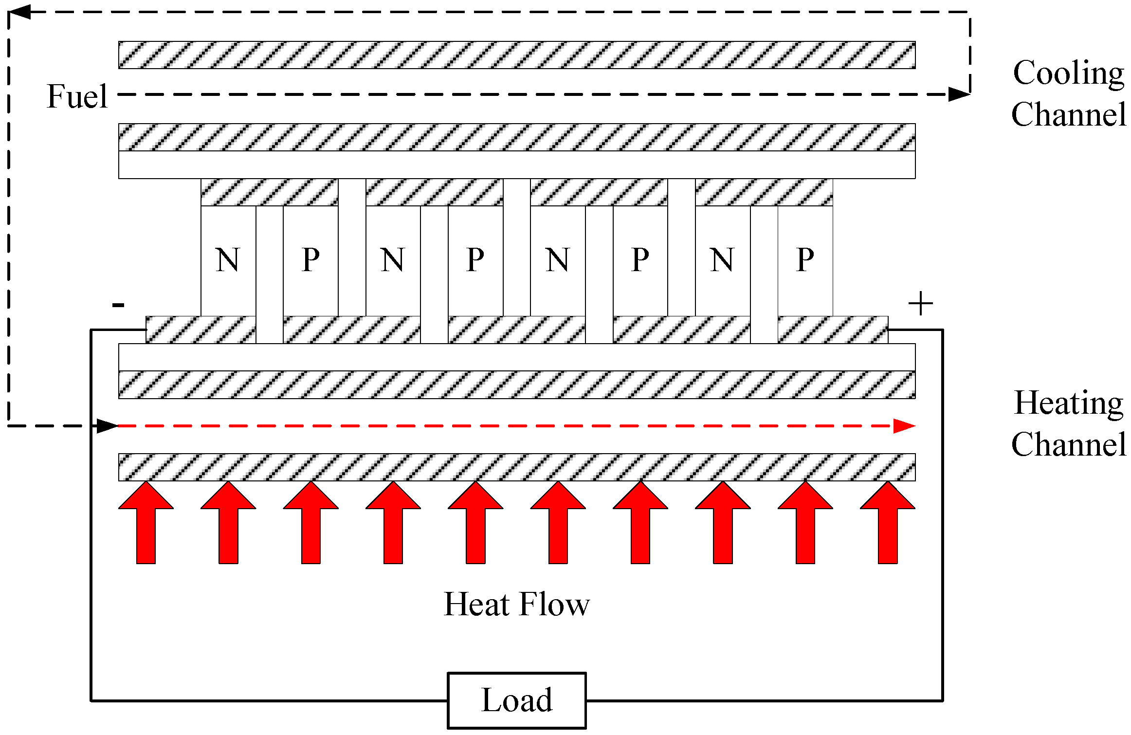
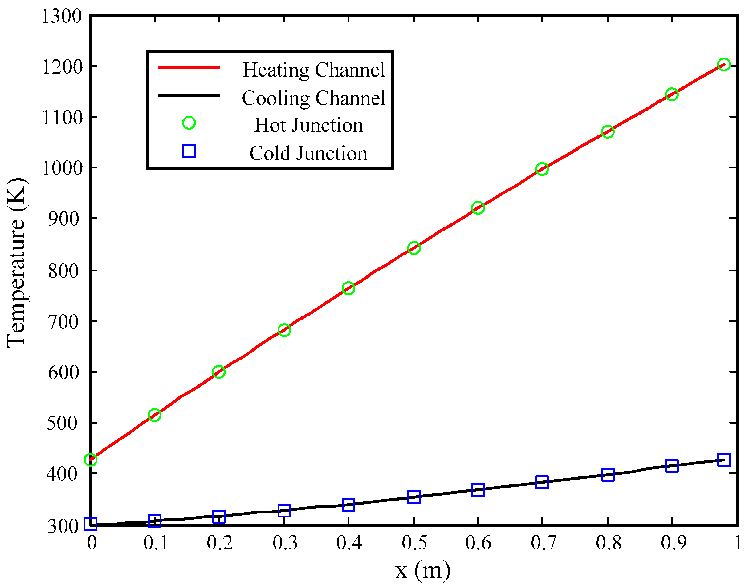
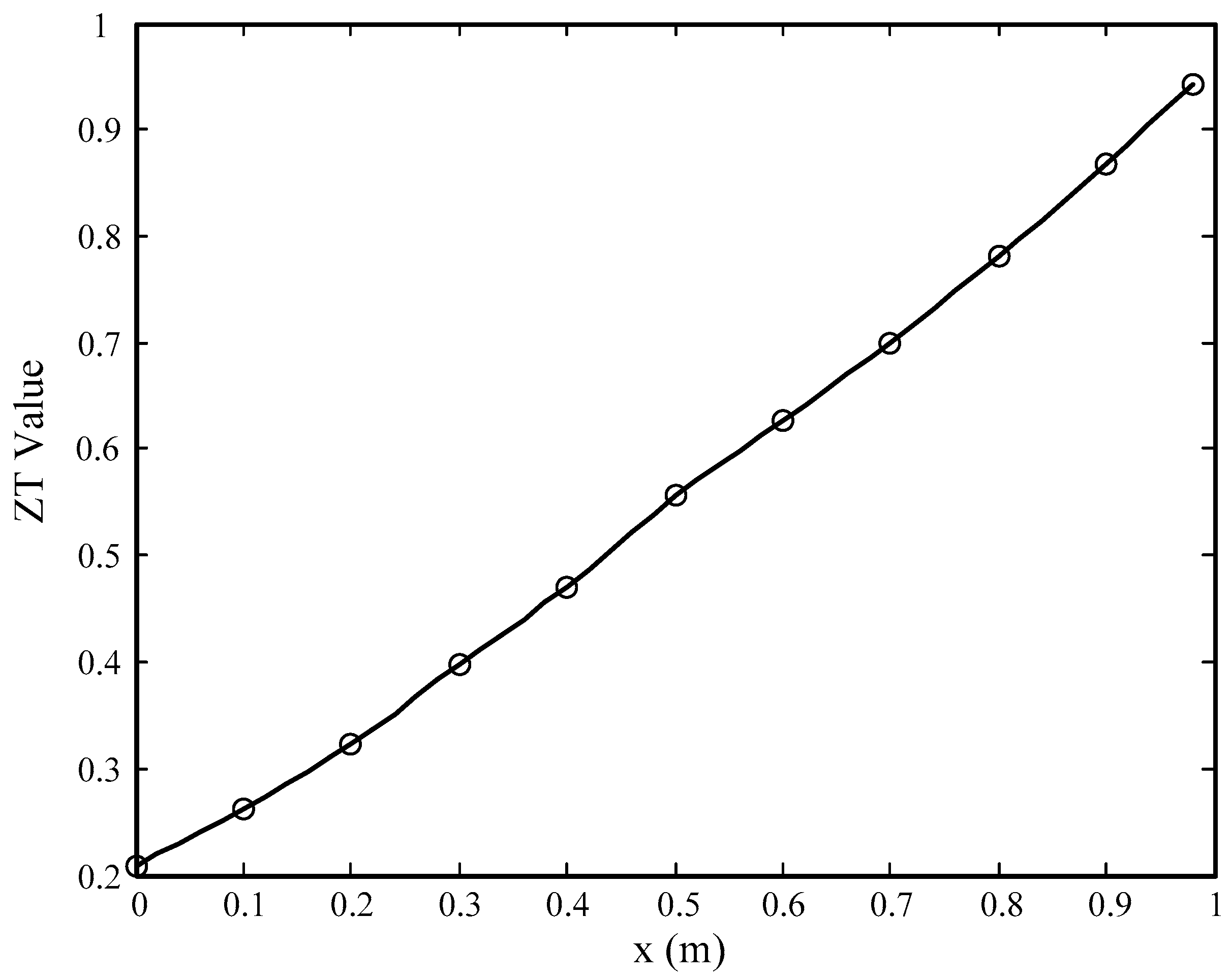
3.3. Variable Temperature Heat Source

To utilize the heat dissipation on the engine walls using thermoelectric generators, the temperature limit of the hot junctions should be the first challenge on account of the fact the temperature of wall surfaces is much higher than the highest temperature that the thermoelectric material can withstand. To avoid the thermal destruction of the thermoelectric material, a thermoelectric generator is designed as shown in Figure 4. The structure of the thermoelectric device is based on the regenerative cooling system used for scramjets. A number of sandwiched thermoelectric couples connected electrically in series and thermally in parallel, are placed between the cooling channels and the heating channels. Note that the heating channels for thermoelectric couples are in fact the cooling channels of the regenerative cooling system. The cold fuel enters the cooling channels to cool the cold junctions and then gets into the heating channels, absorbing the heat dissipation from the flame to the engine walls for thermal protection, and meanwhile providing a heat source for the hot junctions. Due to the finite mass flow rate of fuel, the temperature of the fuel will change a lot along the channels, especially in the heating channels, hence the thermoelectric generators using heat dissipation must be designed with a variable temperature heat source.
The governing equations in the cooling channels are the same as the equations for the thermoelectric generator model with an isothermal heat source, and the equation of conservation of energy and the equation of state in the heating channels are as follows:
m ˙ ( c p Δ T f h Δ x + u f Δ u f Δ x ) = Q t o t Q h Δ x
1 p f Δ p f Δ x = 1 ρ f Δ ρ f Δ x + 1 T f h Δ T f h Δ x
where Qtot is the heat transfer rate from combustion flame to engine walls, which is a constant in this paper.
Similar to the cold junction case, the heat transfer rate of the hot junctions can be expressed as the product of the heat transfer coefficient in the heating channels and the temperature difference between the heated fuel and the hot junction:
Q h = h h A h ( T f h T h )
The calculation of the heat transfer coefficient hh in the heating channels is same with that in the cooling channels.
For the thermoelectric generator with a variable heat source, the temperatures of the hot junctions and the cold junctions should be computed by combining Equations (14), (15), (21) and (27) at same time. The expression for the temperature of cold junctions is:
T c = I 2 R i n ( K + 0.5 α I + 0.5 h h A h ) + K ( h h A h T f h + h c A c T f c ) + h c A c T f c ( α I + h h A h ) α I ( h c A c h h A h α I ) + K ( h c A c + h h A h ) + h c A c h h A h
Then, the temperatures of the hot junctions can be calculated by Tc as follows:
T h = K T c + 0.5 I 2 R i n + h h A h T f h α I + K + h h A h
In this paper, silicon germanium (SiGe) was selected as the thermoelectric material as it is the best thermoelectric material under high temperatures from 800 K to 1200 K. The values of the physical properties for SiGe are supplied by the experimental data in [40]. The calculation of specific heat is supplied by the CHEMKIN-II program [41].

4. Results and Discussion

For a thermoelectric device with an isothermal heat source, the variation of thermoelectric efficiency of the electric current with different hot junction temperatures is shown in Figure 5. There is an optimal electric current point with a maximum thermoelectric efficiency for each hot junction temperature, because the electric power output of TEGs will decrease under too large a current or too low a current, like a battery. The Peltier heat of hot junctions, which is the main heat input for TEMs, will be small if the current is quite low. Meanwhile, the Joule heat, a power loss for electricity generation, will be too large if the current is too high. The thermoelectric efficiency increases with a higher hot junction temperature because of the larger temperature difference between the hot junction and cold junction and a greater ZT value. The details will be discussed below. The maximal thermoelectric efficiency moves to higher currents as the temperature rises, because the amount of Peltier heat is larger at a higher hot junction temperature, which makes the maximal efficiency current higher. The maximum thermoelectric efficiency can reach 5% under a hot junction temperature of 1200 K when the electric current value is about 60 A.
The temperature distribution in the x direction with different hot junction temperatures under the maximum thermoelectric efficiency is shown in Figure 6.
The temperatures of the cold junctions improve along the x direction because of the temperature rise of the fuel in the cooling channels. Meanwhile, the temperatures of the cold junctions increase with the hot junction temperature because of the larger heat flow caused by heat conduction, according to the Fourier law. The growth of the cold junction temperatures is far smaller than the increase of the hot junction temperatures, which means the temperature difference between hot junction and cold junction, one of the main factors to Seebeck effect, improves with the hot junction temperature, too. This is one of the reasons why the thermoelectric efficiency improves with the hot junction temperature. Another reason is that the ZT value, which is always applied to evaluate the thermoelectric efficiency for TEGs, increases with the rise of hot junction temperature as shown in Figure 7, and the ZT value improves along the x direction at the same time. Note that the figure is drawn under the maximum thermoelectric efficiency. The main reason for the increase of ZT value is the improvement of the average temperature of the thermoelectric couples, considering the variation of physical properties with temperature is quite small for the models applied in this paper. The maximum ZT value is approximately 1 for a hot junction temperature of 1200 K, and the maximum value is lower that 0.6 with a hot junction temperature of 800 K. This means that the hot junction temperature has a huge impact on the ZT value for thermoelectric devices with isothermal heat sources.
Note that the temperature difference between the hot and cold junctions is larger than that of the TEGs applied already. A greater temperature difference is beneficial for converting heat into electricity in the TEGs, however, it is a challenge to utilize the temperature difference effectively using a single-stage thermoelectric module at same time. One of the feasible technologies is applying a two-stage semiconductor thermoelectric generator [42], or even a multi-stage one, to increase the number of thermoelectric modules and decrease the temperature difference of each stage.
For thermoelectric generators with a variable temperature heat source, the variation of thermoelectric efficiency of the electric current of circuit is shown as Figure 8. Like the variation laws for TEGs with an isothermal heat source, the thermoelectric efficiency increases with the circuit current first and then decreases with the increase of the electric current because of the variation of electric power. The maximum value of thermoelectric efficiency with the variable temperature heat source is equal to about 2.5%, only half of that of the TEGs with an isothermal heat source when the maximum temperatures of the hot junctions are the same. The reasons for this difference will be discussed later.
The temperature distribution in the x direction for TEGs with a variable temperature source is shown as Figure 9. The temperatures of the hot junctions, the cold junctions, and the fuel in the heating and cooling channels improve with the increase of the heat dissipation from the flame to the engine walls. The temperature of the fuel does not rise excessively in the cooling channels compared with the heating channels, because the amount of heat conduction from the hot junctions to the cold junctions is too small to change the temperature distribution in the cooling channels rapidly. Note that the temperatures of the junctions are almost the same as those of fuel in the channels. The reason is that there is no need for a large temperature difference between the junction and fuel to realize the heat transfer on the walls of channels, considering of the limited heat transfer rate of thermoelectric devices.
As shown in the figure, the maximum temperature of hot junctions is 1200 K, the same as the highest temperature of the hot junctions for the TEGs with an isothermal heat source. However, the thermoelectric efficiency with the variable temperature heat source is far lower than that of the TEGs whose the temperature of heat source is constant, because the temperature of hot junctions with the variable temperature heat source is far below from the temperature of hot junctions under the isothermal heat source, and so is the temperature difference between the hot junction and cold junction. Besides, the rapid variation of hot junction temperature means that it is not reasonable to utilize only one kind of thermoelectric material for TEGs with a variable temperature heat source.
The ZT value distribution along the x direction for the thermoelectric devices with the variable temperature heat source, which is shown as Figure 10, can also indicate that the rapid temperature variation is the reason why the thermoelectric efficiency of the TEGs with the variable temperature heat source is far less than the thermoelectric efficiency with an isothermal heat source for the same value of the highest hot junction temperature. It is obvious that the maximum ZT value is about 0.94, but the minimum value is only 0.2, which is too low for TEGs. The reason is that silicon germanium is not a suitable thermoelectric material for a low temperature application.
In fact, it is not quite fair to compare the performance of TEGs with different kinds of heat source under the same maximal temperature of hot junction, considering the big difference of average temperatures. Hence, it is necessary to compare the conversion efficiency for the two TEGs under the same average temperature, as shown in Table 1. When the average temperatures are identical, the thermoelectric conversion efficiency of the TEG with variable temperature heat source is higher than that of the TEG with an isothermal heat source. The reason is that the high-temperature range for the variable temperature heat source is hotter than that of the isothermal heat source, which is profitable for the thermoelectric conversion using SiGe, whose optimized working temperature range is around 900–1200 K [40].

5. Conclusions and Prospects

The types and the characteristics of the waste heat on the hypersonic flight vehicles have been discussed in this paper. Two thermoelectric device models based on an isothermal heat source and a variable temperature heat source, respectively, are developed to predict the performance of the waste heat recovery systems on a hypersonic flight vehicle with different kinds of heat source. Besides, the thermoelectric efficiency variation with electric current, the temperature distribution of fuel and junctions, and the distribution of the ZT value for both models have been described using diagrams (Figure 5, Figure 6, Figure 7, Figure 8, Figure 9 and Figure 10). The following conclusions are drawn based on calculations and analysis:
(1)
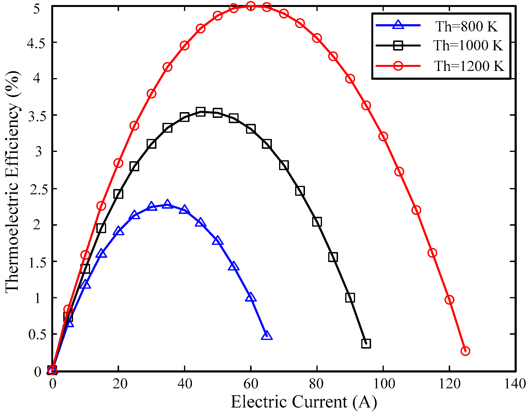
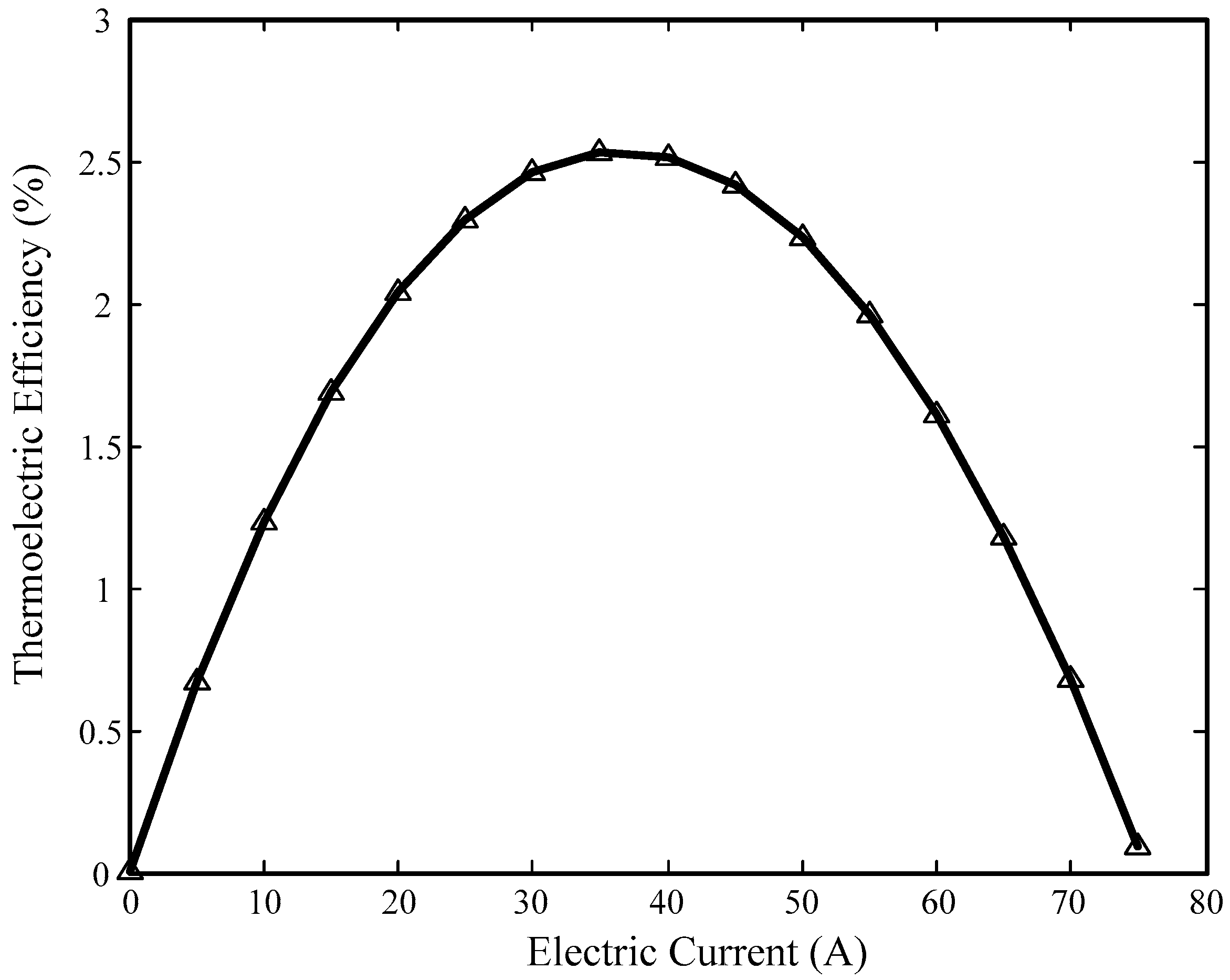
There is an optimal electric current for thermoelectric efficiency for each heat source condition, and the maximum values of the thermoelectric efficiency are 5% and 2.5% for the isothermal heat source and the variable temperature heat source, respectively, under the highest hot junction temperature of 1200 K;
(2)
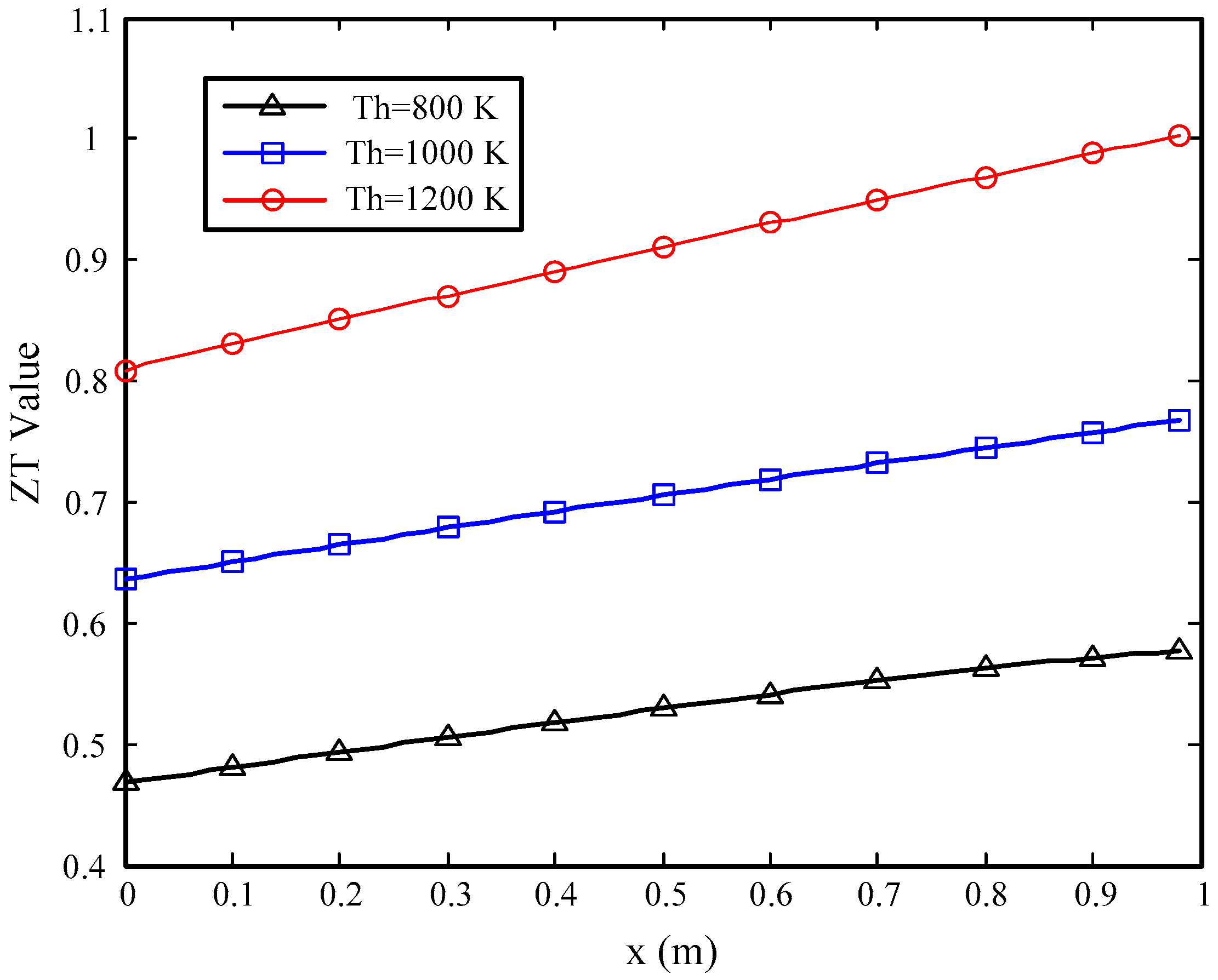
The thermoelectric efficiency of TEGs with an isothermal heat source improves with the temperature of the hot junction because of the increase of the temperature difference between the hot and cold junctions and the ZT value, which can measure the conversion performance of thermoelectric materials;
(3)
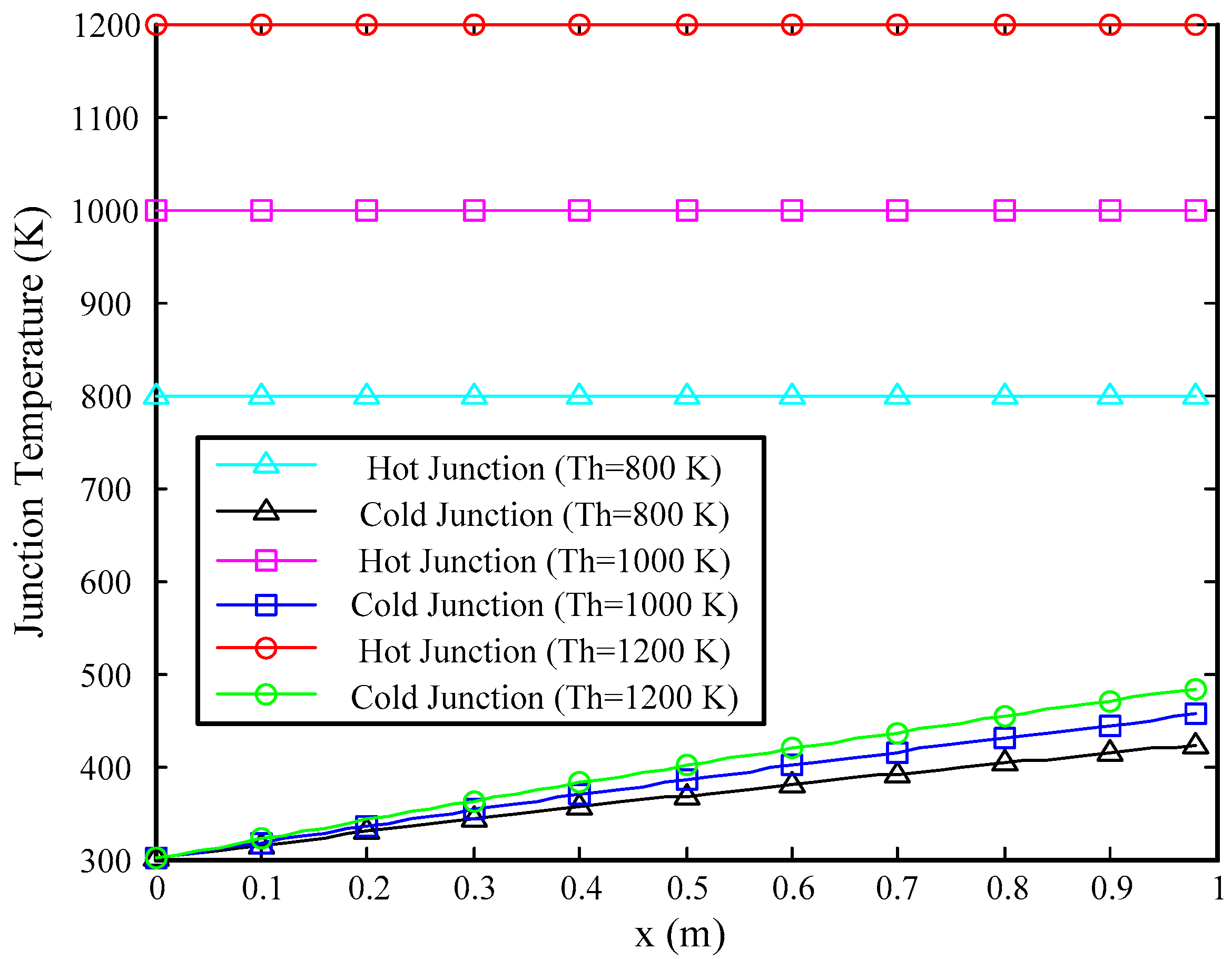
The performance of the TEGs with a variable temperature heat source is worse than that of the TEGs whose heat source temperature is constant for the same highest hot junction temperature, because the average hot junction temperature of the former is far below the hot junction temperature of the latter;
(4)
TEGs with variable temperature heat source have a better conversion efficiency than ones with isothermal heat sources for the same average temperature, because the operating temperature of the former is more suitable for SiGe;
(5)
For a better utilization of the large temperature difference for the waste heat recovery system on a hypersonic flight vehicle, multi-stage semiconductor thermoelectric modules should be used to replace the single-stage ones used at present;
(6)
Considering the huge temperature variation in the x direction for the TEGs with variable temperature heat sources, various thermoelectric materials applicable for different temperature ranges should be applied for a better performance.

Acknowledgments

This research work is supported by Program (Nos. 51476044 and 51606051) and Innovative Research Groups (No. 51421063) of National Natural Science Foundation of China, and Shenzhen Technology Projects (No. JCYJ20160427184254731).

Author Contributions

Kunlin Cheng: Designing of schemes, modeling and article writing. Yu Feng: Analysis of the achieved data. Chuanwen Lv: Cooperating in the scientific discussion. Silong Zhang: English correction. Jiang Qin: Scientific discussion to response the reviewers’ comments. Wen Bao: Analysis of the data.

Conflicts of Interest

The authors declare no conflict of interest.

Nomenclature

AAream2
DhHydraulic diameterm
IElectric currentA
KCoefficient of thermal conductionW/K
NuNusselt numberdimensionless
PPowerW
PrPrandtl numberdimensionless
QHeat transfer rateW
RResistance Ω
ReReynolds numberdimensionless
TTemperature K
UVoltage V
ZTThermoelectric figure of meritdimensionless
cpConstant pressure specific heatJ/(kg·K)
fDrag coefficientdimensionless
hConvection coefficientW/(m2·K)
lLength m
mMass flowratekg/s
pPressure Pa
uVelocity m/s
xDistance m
Greek
αSeebeck coefficientdimensionless
ηThermoelectric efficiencydimensionless
λThermal conductivityW/(m·K)
ρDensity kg/m3
σElectric conductivityΩ·m
Subscripts
JJoule heat
KHeat conduction
LLoad
NN-type
PP-type
cCold
cPPeltier heat of cold junction
fFuel
fcCold fuel
fhHot fuel
hHot
hPPeltier heat of hot junction
inInternal
oOpen-circuit
totTotal

References

  1. Bolender, M.A.; Doman, D.B. Nonlinear longitudinal dynamical model of an air-breathing hypersonic vehicle. J. Spacecr. Rockets 2007, 44, 374–387. [Google Scholar] [CrossRef]
  2. Newman, R.W. Oxidation-resistant high-temperature materials. Johns Hopkins APL Tech. Dig. 1993, 14, 24–28. [Google Scholar]
  3. Curran, E.T. Scramjet engines: The first forty years. J. Propuls. Power 2001, 17, 1138–1148. [Google Scholar] [CrossRef]
  4. Walker, S.; Tang, M.; Mamplata, C. TBCC propulsion for a Mach 6 hypersonic airplane. In Proceedings of the 16th AIAA/DLR/DGLR International Space Planes and Hypersonic Systems and Technologies Conference, Bremen, Germany, 19–22 October 2009. [Google Scholar]
  5. Yang, Q.C.; Shi, W.; Chang, J.T.; Bao, W. Maximum thrust for the rocket-ejector mode of the hydrogen fueled rocket-based combined cycle engine. Int. J. Hydrogen Energy 2015, 40, 3771–3776. [Google Scholar] [CrossRef]
  6. Jin, H.G.; Hong, H.; Wang, B.Q.; Han, W.; Lin, R.M. A new principle of synthetic cascade utilization of chemical energy and physical energy. J. Sci. China Ser. E Eng. Mater. Sci. 2005, 48, 163–179. [Google Scholar] [CrossRef]
  7. Tartakovsky, L.; Gutman, M.; Mosyak, A. Energy efficiency of road vehicles—Trends and challenges. In Energy Efficiency: Methods, Limitations and Challenges; Santos Cavalcanti, E., Barbosa, M., Eds.; Nova Science Publishers: New York, NY, USA, 2012; pp. 63–90. [Google Scholar]
  8. Shu, G.Q.; Zhao, M.R.; Tian, H.; Wei, H.Q.; Liang, X.Y.; Huo, Y.Z.; Zhu, W.J. Experimental investigation on thermal OS/ORC (Oil Storage/Organic Rankine Cycle) system for waste heat recovery from diesel engine. Energy 2016, 107, 693–706. [Google Scholar] [CrossRef]
  9. Serrano, J.R.; Olmeda, P.; Tiseira, A.; García-Cuevas, L.M.; Lefebvre, A. Theoretical and experimental study of mechanical losses in automotive turbochargers. Energy 2013, 55, 888–898. [Google Scholar] [CrossRef]
  10. Mamat, A.M.I.; Romagnoli, A.; Martinez-Botas, R.F. Characterisation of a low pressure turbine for turboncompounding applications in a heavily downsized mild-hybrid gasoline engine. Energy 2014, 64, 3–16. [Google Scholar] [CrossRef]
  11. Poran, A.; Tartakovsky, L. Energy efficiency of a direct-injection internal combustion engine with high-pressure methanol steam reforming. Energy 2015, 88, 506–514. [Google Scholar] [CrossRef]
  12. Javani, N.; Dincer, I.; Naterer, G.F. Thermodynamic analysis of waste heat recovery for cooling systems in hybrid and electric vehicles. Energy 2012, 46, 109–116. [Google Scholar] [CrossRef]
  13. Zhu, S.P.; Deng, K.Y.; Qu, S.A. Thermodynamic analysis of an in-cylinder waste heat recovery system for internal combustion engines. Energy 2014, 67, 548–556. [Google Scholar] [CrossRef]
  14. Sun, X.X.; Liang, X.Y.; Shu, G.Q.; Tian, H.; Wei, H.Q.; Wang, X.X. Comparison of the two-stage and traditional single-stage thermoelectric generator in recovering the waste heat of the high temperature exhaust gas of internal combustion engine. Energy 2014, 77, 489–498. [Google Scholar] [CrossRef]
  15. Pramanick, A.K.; Das, P.K. Constructal design of a thermoelectric device. Int. J. Heat Mass Transf. 2006, 49, 1420–1429. [Google Scholar] [CrossRef]
  16. Gou, X.L.; Xiao, H.; Yang, S.W. Modeling, experimental study and optimization on low-temperature waste heat thermoelectric generator system. Appl. Energy 2010, 87, 3131–3136. [Google Scholar] [CrossRef]
  17. Bass, J.C.; Elsner, N.B.; Leavitt, F.A. Performance of the 1 kW thermoelectric generator for diesel engines. In Proceedings of the 13th International Conference on Thermoelectrics, Kansas City, MO, USA, 30 August–1 September 1994; pp. 295–298. [Google Scholar]
  18. Kushch, A.S.; Bass, J.C.; Ghamaty, S.; Elsner, N.B. Thermoelectric development at Hi-Z technology. In Proceedings of the 20th International Conference on Thermoelectrics, Beijing, China, 8–11 June 2001; pp. 422–430. [Google Scholar]
  19. Matsubara, K. Development of a high efficient thermoelectric stack for a waste exhaust heat recovery of vehicles. In Proceedings of the 21st International Conference on Thermoelectronics, Long Beach, CA, USA, 25–29 August 2002; pp. 418–423. [Google Scholar]
  20. Yang, J. Potential applications of thermoelectric waste heat recovery in the automotive industry. In Proceedings of the 24th International Conference on Thermoelectrics, Clemson, SC, USA, 19–23 June 2005; pp. 155–159. [Google Scholar]
  21. LaGrandeur, J.; Crane, D.; Hung, S.; Mazar, B.; Eder, A. Automotive waste heat conversion to electric power using skutterudite, TAGS, PbTe and BiTe. In Proceedings of the International Conference on Thermoelectrics, Vienna, Austria, 6–10 August 2006; pp. 343–348. [Google Scholar]
  22. Saqr, K.M.; Mansour, M.K.; Musa, M.N. Thermal design of automobile exhaust based thermoelectric generators: Objectives and challenges. Int. J. Automot. Technol. 2008, 9, 155–160. [Google Scholar] [CrossRef]
  23. Minnich, A.J.; Dresselhaus, M.S.; Ren, Z.F.; Chen, G. Bulk nanostructured thermoelectric materials: Current research and future prospects. Energy Environ. Sci. 2009, 2, 466–479. [Google Scholar] [CrossRef]
  24. Venkatasubramanian, R.; Siivola, E.; Colpitts, T.; O’Quinn, B. Thin-film thermoelectric devices with high room-temperature figures of merit. Nature 2001, 413, 597–602. [Google Scholar] [CrossRef] [PubMed]
  25. Harman, T.C.; Taylor, P.J.; Walsh, M.P.; LaForge, B.E. Quantum dot superlattice thermoelectric materials and devices. Science 2002, 297, 2229–2232. [Google Scholar] [CrossRef] [PubMed]
  26. Hochbaum, A.I.; Chen, R.; Delgado, R.D.; Liang, W.; Garnett, E.C.; Najarian, M.; Majumdar, A.; Yang, P. Enhanced thermoelectric performance of rough silicon nanowires. Nature 2008, 451, 163–167. [Google Scholar] [CrossRef] [PubMed]
  27. Poudel, B.; Hao, Q.; Ma, Y.; Lan, Y.C.; Minnich, A.; Yu, B.; Yan, X.; Wang, D.Z.; Muto, A.; Vashaee, D.; et al. High-thermoelectric performance of nanostructured bismuth antimony telluride bulk alloys. Science 2008, 320, 634–638. [Google Scholar] [CrossRef] [PubMed]
  28. Heremans, J.P.; Jovovic, V.; Toberer, E.S.; Saramat, A.; Kurosaki, K.; Charoenphakdee, A.; Yamanaka, S.; Snyder, G.J. Enhancement of thermoelectric efficiency in PbTe by distortion of the electronic density of states. Science 2008, 321, 554–557. [Google Scholar] [CrossRef] [PubMed]
  29. Pei, Y.L.; Liu, Y. Electrical and thermal transport properties of Pb-based chalcogenides: PbTe, PbSe, and PbS. J. Alloys Compd. 2012, 514, 40–44. [Google Scholar] [CrossRef]
  30. Jiang, Z.W.; Zhang, W.L.; Yan, L.Q.; Niu, X.H. Anisotropy of the Seebeck coefficiency in Czochralski grown p-type SiGe single crystal. Mater. Sci. Eng. B Solid State Mater. Adv. Technol. 2005, 119, 182–184. [Google Scholar] [CrossRef]
  31. Blosser, M.L.; Chen, R.R.; Schmidt, I.H.; Dorsey, J.T.; Poteet, C.C.; Bird, R.K. Advanced Metallic Thermal Protection System Development. In Proceedings of the 40th Aerospace Science Meeting & Exhibit (AIAA-2002-0504), Reno, NV, USA, 14–17 January 2002; pp. 1–20. [Google Scholar]
  32. Kanda, T.; Masuya, G.; Wakamatsu, Y. Propellant feed system of a regeneratively cooled scramjet. J. Propuls. Power 1991, 7, 299–301. [Google Scholar] [CrossRef]
  33. Qin, J.; Cheng, K.L.; Zhang, S.L.; Zhang, D.; Bao, W.; Han, J.C. Analysis of energy cascade utilization in a chemically recuperated scramjet with indirect combustion. Energy 2016, 114, 1100–1106. [Google Scholar] [CrossRef]
  34. Zhang, D.; Feng, Y.; Zhang, S.L.; Qin, J.; Cheng, K.L.; Bao, W.; Yu, D.R. Quasi-one-dimensional model of scramjet combustor coupled with regenerative cooling. J. Propuls. Power 2016, 32, 687–697. [Google Scholar] [CrossRef]
  35. Zhou, W.X.; Jia, Z.J.; Qin, J.; Bao, W.; Yu, B. Experimental study on effect of pressure on heat sink of n-decane. Chem. Eng. J. 2014, 243, 127–136. [Google Scholar] [CrossRef]
  36. Zhang, D.; Cheng, K.L.; Zhang, S.L.; Qin, J.; Bao, W. Graphical Exergy Analysis for a Scramjet Thermodynamic Performance Evaluation. Int. J. Exergy 2016, 21, 136–156. [Google Scholar] [CrossRef]
  37. Chen, J.C.; Lin, B.H.; Wang, H.J.; Lin, G.X. Optimal design of a multi-couple thermoelectric generator. Semicond. Sci. Technol. 2000, 15, 184–188. [Google Scholar] [CrossRef]
  38. Qin, J.; Zhang, S.L.; Bao, W.; Yu, W.L.; Yu, B.; Zhou, W.X.; Yu, D.R. Experimental study on chemical recuperation process of endothermic hydrocarbon fuel. Fuel 2013, 108, 445–450. [Google Scholar] [CrossRef]
  39. Locke, J.M.; Landrum, D.B. Uncertainty analysis of heat transfer to supercritical hydrogen in cooling channels. In Proceedings of the 41st AIAA/ASME/SAE/ASEE Joint Propulsion Conference & Exhibit, Joint Propulsion Conferences, Tucson, AZ, USA, 10–13 July 2005. [Google Scholar]
  40. Suo, K.N. The Study on Thermoelectric Property of SiGe Alloy at High Temperature. Master’s Thesis, Hebei University of Technology, Tianjin, China, 2007. (In Chinese). [Google Scholar]
  41. Kee, R.J.; Rupley, F.M.; Miller, J.A. CHEMKIN-II: A Fortran Chemical Kinetics Package for the Analysis of Gas Phase Chemical kinetics; Rept. SAND89-8009B; Sandia National Lab.: Albuquerque, NM, USA, April 1989. [Google Scholar]
  42. Chen, L.G.; Li, J.; Sun, F.R.; Wu, C. Performance optimization of a two-stage semiconductor thermoelectric-generator. Appl. Energy 2005, 82, 300–312. [Google Scholar] [CrossRef]
Figure 1. Waste heat types on a hypersonic flight vehicle.
Energies 10 00570 g001
Figure 2. Sketch of a thermoelectric device with an isothermal heat source.
Energies 10 00570 g002
Figure 3. Calculation model of the cooling process.
Energies 10 00570 g003
Figure 4. Sketch of a thermoelectric device with a variable temperature heat source.
Energies 10 00570 g004
Figure 5. Variation of thermoelectric efficiency of the electric current with different hot junction temperatures for TEGs with isothermal heat sources.
Energies 10 00570 g005
Figure 6. Temperature distribution along x direction with different hot junction temperatures for TEGs with isothermal heat source.
Energies 10 00570 g006
Figure 7. ZT value distribution along the x direction with different hot junction temperatures for TEGs with isothermal heat sources.
Energies 10 00570 g007
Figure 8. Variation of the thermoelectric efficiency of the electric current for TEGs with variable temperature heat sources.
Energies 10 00570 g008
Figure 9. Temperature distribution along the x direction for TEGs with variable temperature heat sources.
Energies 10 00570 g009
Figure 10. ZT value distribution along the x direction for TEGs with a variable temperature heat source.
Energies 10 00570 g010
Table 1. Conversion efficiency comparison under the same average temperature.
Conversion Efficiency (%)Average Temperature (K)
500525550575600
Isothermal Heat Source1.361.611.892.182.48
Variable Temperature Heat Source1.491.762.042.322.63

