Design and Research of the Movable Hybrid Photovoltaic-Thermal (PVT) System

Department of New Energy, Tianjin Sino-German University of Applied Sciences, Tianjin 300350, China
*
Author to whom correspondence should be addressed.
Energies 2017, 10(4), 507; https://doi.org/10.3390/en10040507
Submission received: 1 February 2017
/
Revised: 17 March 2017
/
Accepted: 5 April 2017
/
Published: 8 April 2017
(This article belongs to the Special Issue Solar Photovoltaics Trilemma: Efficiency, Stability and Cost Reduction 2017)
Abstract
:In recent years, with the development of photovoltaic system and photo-thermal system technology, hybrid photovoltaic-thermal (PVT) technology has been a breakthrough in many aspects. This paper describes the movable hybrid PVT system from the aspects of appearance structure, energy flow, and control circuit. The system is equipped with rolling wheels and the simulated light sources also can be removed so that the system can be used in the outdoor conditions. The movable system is also suitable for the PVT system and its related applications without any external power supply. This system combines two technologies: photovoltaic power generation and photo-thermal utilization. The first part of the power supply is for the systems own output power supply, and the second part is for generating thermal energy. The two separate parts can be controlled and monitored respectively through the control circuits and the touch screens. The experimental results show that the system can generate 691 kWh electric energy and 3047.8 kWh thermal energy each year under normal working conditions. The efficiency of the proposed movable hybrid PVT system is calculated to be approximately 42.82% using the revised equations that are proposed in this paper. Therefore, the movable hybrid PVT system can meet the daily demands of hot water and electricity power in remote areas or islands and other non-grid areas. It also can be used to conduct experiment tests for the PVT system.
1. Introduction
The use and development of solar energy began as early as 1959, when the patents for photovoltaic (PV) and photo-thermal (PT) technologies first appeared in United States [1,2]. In recent years, researchers have mainly focus on a holistic approach to PV and PT. Xiong and Walsh [3] studied PV modules under high temperature, pressure, and humidity conditions. Khoo and Nobre [4] studied the optimum tilt angle of PV systems. Work on PV cells made of self-assembly polymer was published in Nature Materials by Gang et al. [5]. Lu et al. [6] studied the thermal performance of heat absorption tubes in a flat plate collector. A new type of controller for PT system was designed by Lin et al. [7]. Zhang and Zhang [8,9] studied heat recovery technology for PT system. Kamel et al. [10] made a review of existing PT systems.
At the same time, researchers have carried out a large number of design and development for the hybrid photovoltaic-thermal (PVT) system. Joshi et al. [11] analyzed the efficiency of the PVT system. Zhang et al. [12] summarized the development and application of the existing PVT systems. The performance of an integrated photovoltaic and thermal solar system compared to a conventional system was evaluated by Huang et al. [13] in that study, the efficiency of the proposed integrated photovoltaic and thermal solar system was higher than the conventional system.
Movable solar systems have been designed and tested in different studies. A mobile PV hybrid power system for use in remote areas was designed by Prompinit et al. [14]. The unit was constructed in a container unit that could be easily moved. A serial experiment showed that the system could work thanks to the design and operation stability of the power supply to the load. Eroglu et al. [15] tested a mobile renewable house using a PV/wind/fuel cell hybrid power system. The mobile house could produce sufficient power to meet the peak load as the stand-alone power system in remote areas and in certain situations such as natural disasters. Photovoltaic and wind energy are used as primary power sources for the mobile house system.
In this paper, a design of a movable hybrid PVT system is presented. The design and construction of the appearance structure, energy flow, and control circuit are introduced in detail. The actual efficiency and power generation of the proposed system are obtained by testing the system and analyzing the data. The comparisons between the proposed study and the former study are also discussed.
2. The Appearance Structure Design
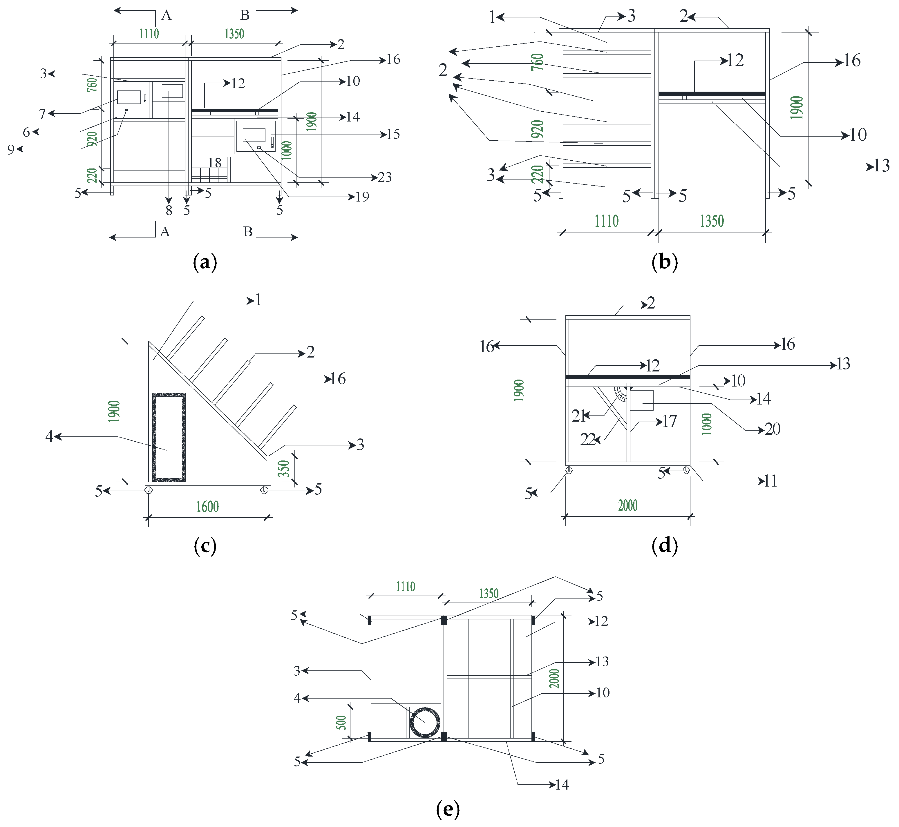
The appearance structure consists of solar flat plate collector (2000 mm × 1060 mm × 80 mm), PV modules (1980 mm × 1336 mm × 40 mm), simulated light sources, a moving frame, a water tank, batteries, rolling wheels, a control cabinet, a switch box, a touch screen, and so on. Figure 1 shows different views of the appearance, the front view, the back view, the sectional view, and the bottom view. Table 1 describes the components according to the Figure 1. A photo of the structure is presented in Figure 2. From Figure 1, the solar flat plate collector and the PV modules that under the simulated light sources are mounted on the moving frame side by side. The water tank is installed in the left moving frame. The batteries are installed in the right moving frame. The rolling wheels are placed at the bottom of the moving frame.
The sunlight projected on the PV modules can be absorbed and transformed into electric energy according to the PV effect. The generated electric energy can be stored in the batteries that can supply energy for the whole movable hybrid PVT system and can also be used for external load. The sunlight projected onto the absorber plate inside the solar flat plate collector can be absorbed and transformed into thermal energy. Then the thermal energy is transferred to the water pipes under the absorber plate, increasing the temperature of the water. The water circulates in the water pipes, which are connected to the solar flat plate collector and the water tank. The water in the water tank warms up and can be used gradually for daily use. For indoor conditions, the simulated light sources are used to simulate sunlight that can be used to the experiments with the PV and PT systems. The simulated light sources contain 20 light source and the power of every light source is 200 W. Half of the simulated light sources are arranged in a rectangle (5 × 2) and placed on the top of PV modules, and the rest of the simulated light sources are arranged in another rectangle (5 × 2) and placed evenly on the top of solar flat plate collector. For this design, the PV modules and solar flat plate collector receive light uniformly, which ensures that the experiments operate under the same conditions. In order to change the tilt angle of the PV modules, the rotary bar of the PV power generator can be rotated quantitatively through the protractor and the adjustment bracket of the PV power generator. The system is equipped with rolling wheels that can be used in outdoor conditions, giving the system the advantages of mobility and environment adaptability. According to the positive view, the system includes two sets of control cabinets, switch boxes, and touch screen to control the PV power generation and PT thermal utilization, respectively.
3. Energy Flow
The main function of the proposed PVT system is to convert solar energy into electric energy and thermal energy using the PV modules and the solar flat plate collector, respectively. The energy flow in this system can be divided into two parts: PV power generation and PT thermal utilization.
3.1. PV Power Generation
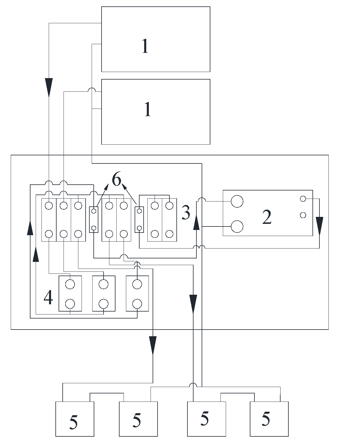
The energy flow of the PV power generation is shown in Figure 3. Table 2 describes the components according to the Figure 3. The PV power generation path is mainly composed of PV modules, batteries, switches, relays, fuses, and an inverter. Two polycrystalline silicon PV modules are connected in parallel to generate electric energy under the irradiation of sunlight or simulated light sources. The optimal working voltage of each PV module is 31.5 V, and the peak power of each PV module is 250 W. Two PV modules are connected through two switches to the two relays that control the output of the PV modules, and then connected to four batteries through two switches. Each of the two batteries are connected in series and then connected in parallel. When the PV modules are working, the electric energy generated by the PV modules can flow into the batteries, which are used for storing electric energy. The rated voltage of each battery is 12 V, and the two batteries are connected in series to 24 V. Electric energy from the PV modules and the batteries can be supplied to the components of the PV power generation, the PT thermal utilization (including DC (direct current) water pump, the electromagnetic valve, the relays, the ultrasonic heat meter, the conversion module, the liquid level sensor, the touch screen, the input/output (I/O) board, and the control circuit. The electric energy can also enter the inverter through the switches, the relay, and the fuse. The inverter converts the 24 V DC to the 220 V alternating current (AC), and then the 220 V AC is supplied through another fuse and the switch to the external AC load. The two fuses are used to protect the input and output of the inverter, respectively.
3.2. PT Thermal Utilization
The energy flow of PT thermal utilization is shown in Figure 4. Table 3 describes the components according to the Figure 4. PT thermal utilization is mainly composed of a solar flat plate collector, a water tank, a DC water pump, an electromagnetic valve, a manual valve, an ultrasonic heat meter, a liquid level sensor, and an electric auxiliary heater. Water is the carrier of energy in PT thermal utilization. The function of the DC pump is to continuously drive the water through the circulated water pipe between the solar flat plate collector and the water tank. The ultrasonic heat meter is used for the measurement of experimental data.
The water is connected between the components by the circulated water pipe. Cold water enters the solar flat plate collector through the DC pump. The solar flat plate collector absorbs the thermal energy from sunlight or simulate sunlight from light sources and then heats the cold water in the circulated water pipe. The water inlet of the water tank is connected to the solar flat plate collector. The hot water in the solar flat plate collector enters the water tank and mixes with the cold water in the water tank. The water in the tank is distributed according to the temperature gradient. The lower temperature water enters the solar flat plate collector from the water outlet so that the water can be circulated by the DC water pump in order to the water in the whole water tank. The electromagnetic valve is arranged between the water inlet and the external water source. The water can be supplied from the external water source to the water inlet when the electromagnetic valve open. The drainage terminal is used to release the hot water and is connected to the water outlet. The liquid level sensor can measure the liquid level of the water in the water tank, and the electric auxiliary heater provides auxiliary heating for the water in the water tank. The ultrasonic heat meter and the liquid level sensor feedback the data to the control system that operates of the DC pump, the electromagnetic valve, and the electric auxiliary heater. When this system works in indoor conditions, the simulated light sources and electric auxiliary heater can be supplied by external AC power.
4. The Control Circuit
The control circuit of this system can be divided into two parts: PV power generation and PT thermal utilization.
4.1. PV Power Generation
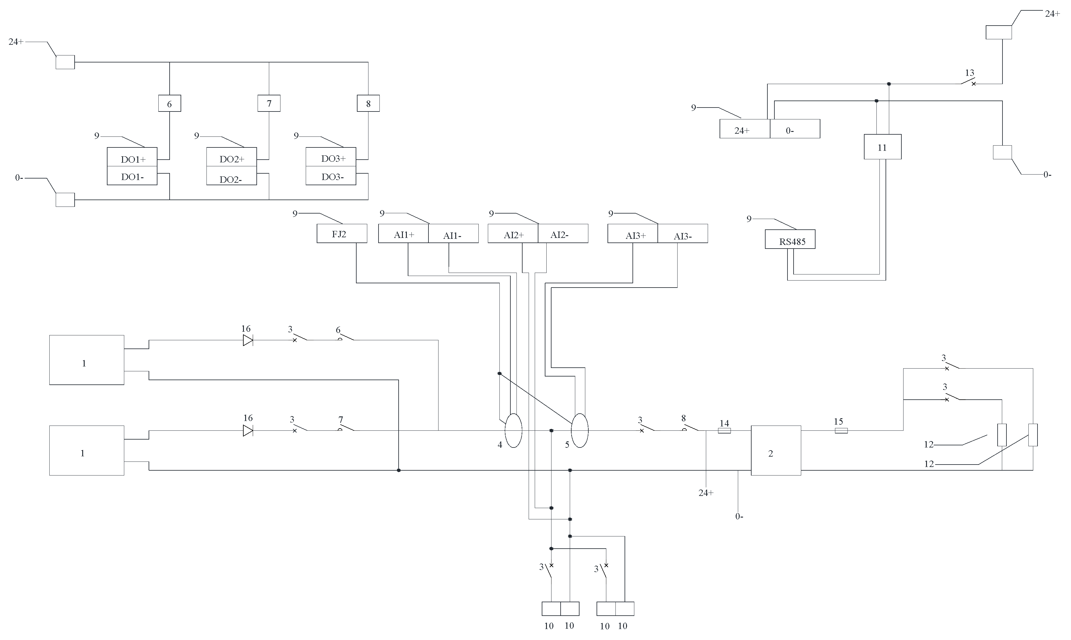
The control circuit of the PV power generation is shown in Figure 5. Table 4 describes the components according to the Figure 5. The electric energy generated by the light from the PV modules enters into the batteries and other loads through the terminal block, the switches, and the relay. The DC current sensors obtain the current values from the related components in this process. Data acquisition is carried out in the I/O acquisition board. This data is fed back on the touch screen, which can be used to display and adjust the power supply status. The I/O board controls the related components according to the commands of the touch screen or the automatic program. The generated current value, the discharged current value, and the batteries’ voltage value can be obtained so that the real-time power generation and the cumulative power generation can be calculated. The parameters of the PV power generation can be adjusted using the touch screen.
The DO1 port and the DO2 port of the I/O board control the output of the PV modules through two relays. The DO3 port controls the input of the inverter by the relay. The I/O board and the touch screen are provided with energy by the batteries. The DC current sensors are provided with energy by the FJ2 port of the I/O board. The two DC current sensors collect the output current value of the PV modules and the input current value of the inverter, then transmit them to the AI1 port and the AI3 port of the I/O board. The voltage value of the batteries is transmitted to the AI2 port of the I/O board. The I/O board will get the data back to the touch screen through the RS485 port.
4.2. PT Thermal Utilization
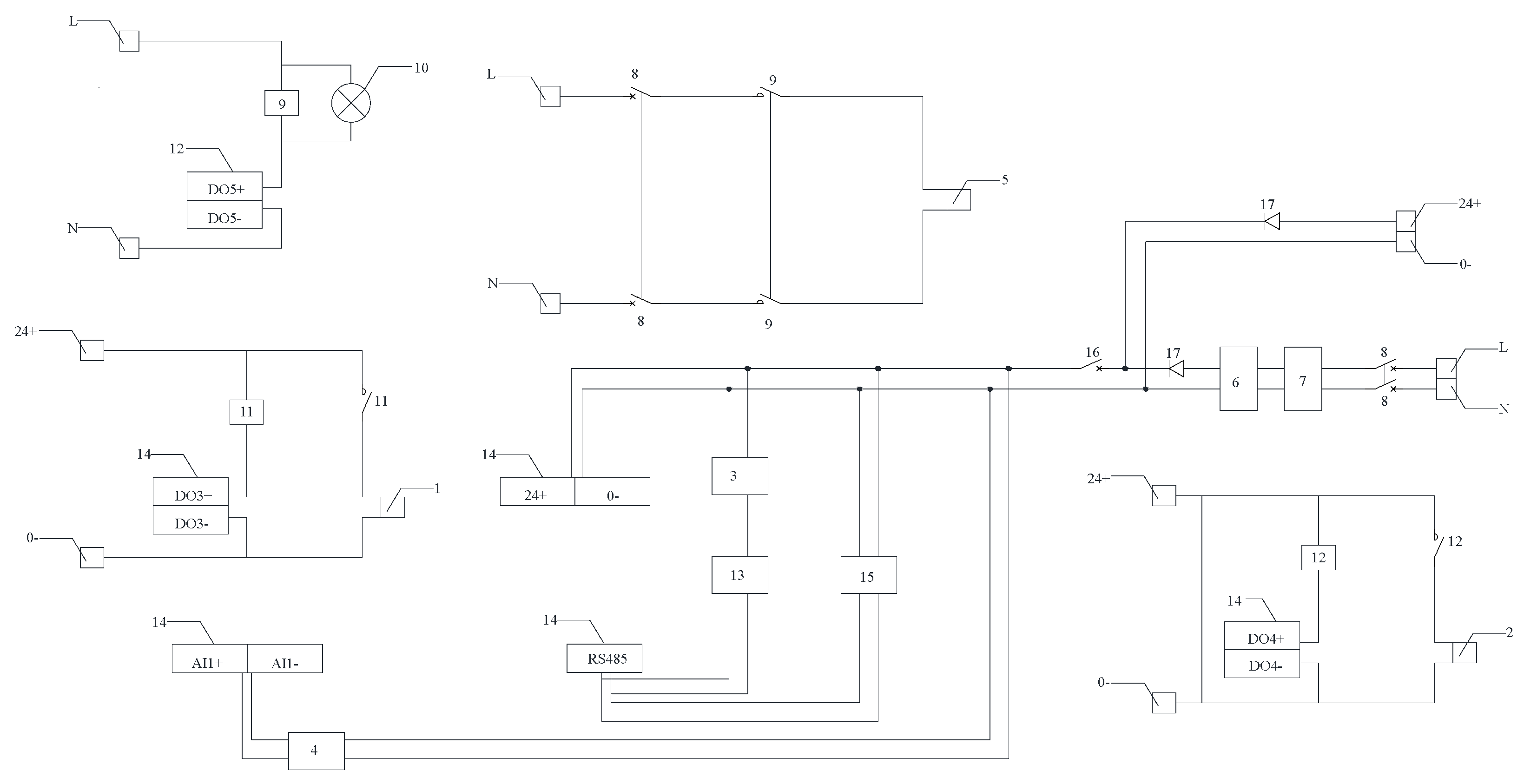
The control circuit of the PT thermal utilization is shown in Figure 6. Table 5 describes the components according to the Figure 6. The rectifier and transformer’s main function is when the batteries’ power is not enough, the external AC 220 V can be converted into DC 24 V power to supply the system. The switches, the AC contactor, and the relays are mainly used for controlling the main circuit. The AC contactor is used for controlling the electric auxiliary heater, and the two relays are used for controlling the DC water pump and the electromagnetic valve, respectively. The pilot lamp is used to display the status of the AC contactor. The ultrasonic heat meter uses the M-Bus protocol, which is different from the communication mode of the I/O board (RS485). The conversion module is used to meet the requirements of the I/O board. The I/O board controls the related components according to the command of the touch screen or the automatic program. The touch screen can be used to display and adjust the power supply status. The liquid level of the water tank, the accumulated thermal energy, and real-time temperature from the ultrasonic heat meter can be obtained. The parameters of the PT thermal utilization can be adjusted using the touch screen.
In order to facilitate communication between the ultrasonic heat meter, the touch screen, and the I/O board, the COM interface of the I/O board is connected to the conversion module and the touch screen. The AI1 port of the I/O board obtains data from the liquid level sensor. The DO3 port and the DO4 port of the I/O board control the DC water pump and the electromagnetic valve. The DO5 port controls the AC contactor and the pilot lamp. Furthermore, the electric auxiliary heater is also controlled.
5. System Test and Results Analysis
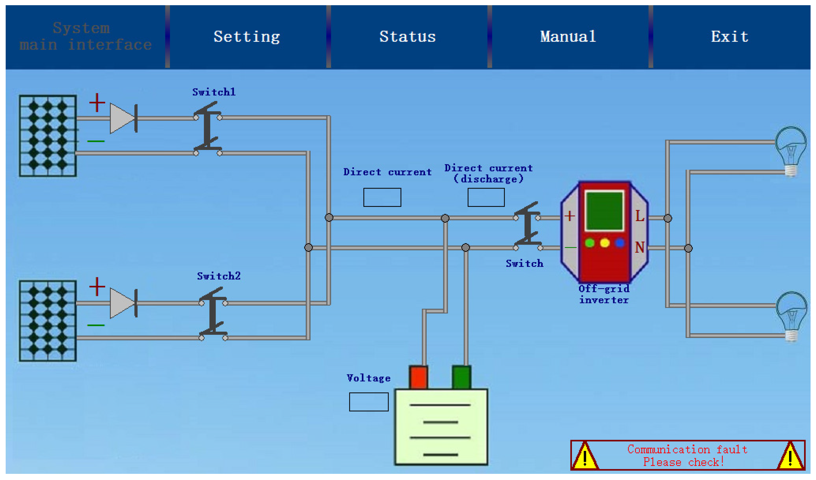
The monitoring and data acquisition system (DAQ) depends on the Monitor and Control Generated System(MCGS) configuration technology of the touch screen that can monitor the status of the system and collect real-time data through communication with the I/O board. In Figure 7, it can see that that PV power generation and PT thermal utilization are respectively controlled by two touch screens and two I/O boards.
5.1. PV Power Generation
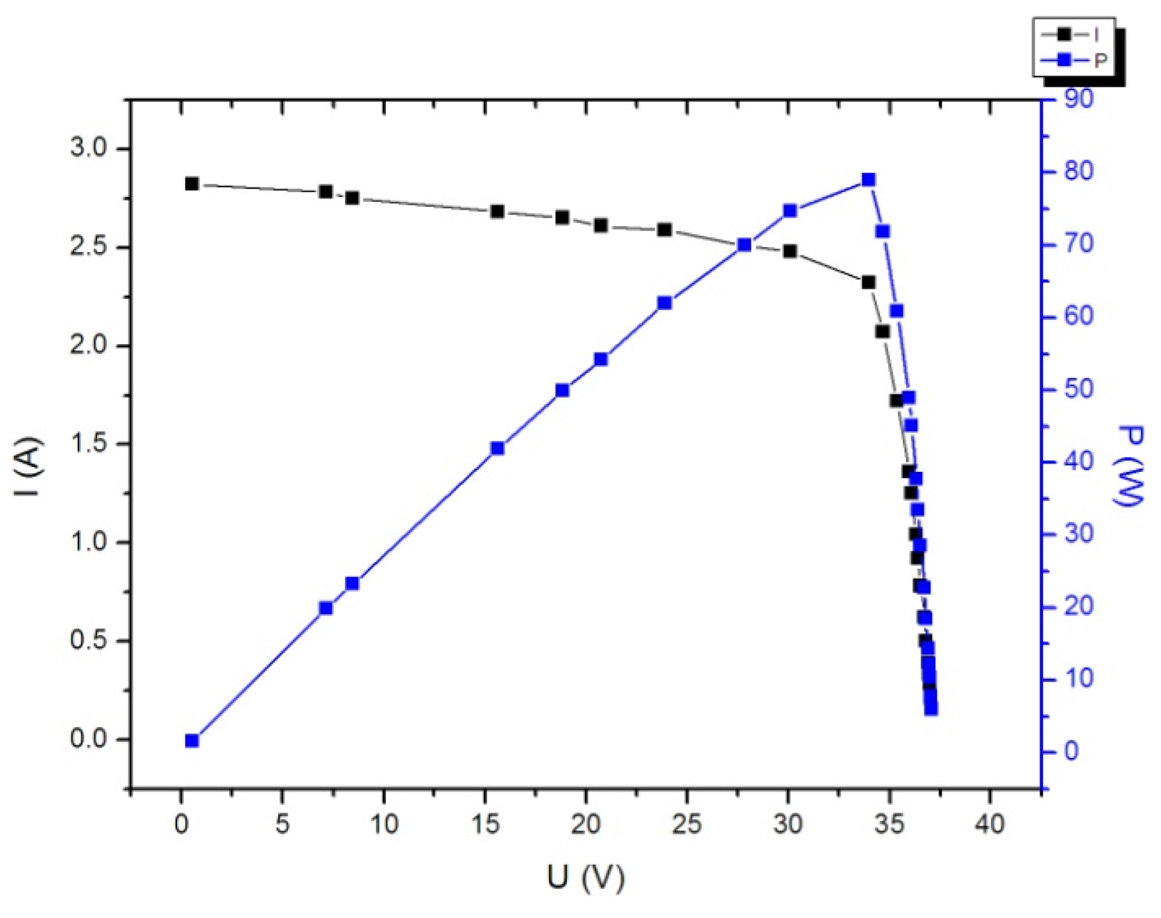
The status of PV power generation can be monitored and controlled. At the same time, the current voltage, open circuit voltage, short circuit current, and other parameters of PV power generation can be collected and the relevant parameters can be adjusted, as shown in Figure 7. According to the collected parameters, the V-I characteristic curve, the power output curve, and the maximum power point can be obtained, as shown in Figure 8.
The fill factor of PV power generation can be calculated according to Equation (1):
where FF is the fill factor of PV power generation, %; PMAX the maximum power of PV power generation, kW; UOC the open circuit voltage of PV power generation, V; and ISC the short-circuit current of PV power generation, A.
The cumulative electric amount of PV power generation can be calculated according to Equation (2):
where Et is the cumulative amount of PV power generation, kWh; the real-time voltage of PV power generation, V; the real-time current of PV power generation, A; and the cumulative time, s.
The generated electric energy by PV power generation can be calculated from these equations. The system can generate 691 kWh of electricity per year.
5.2. PT Thermal Utilization
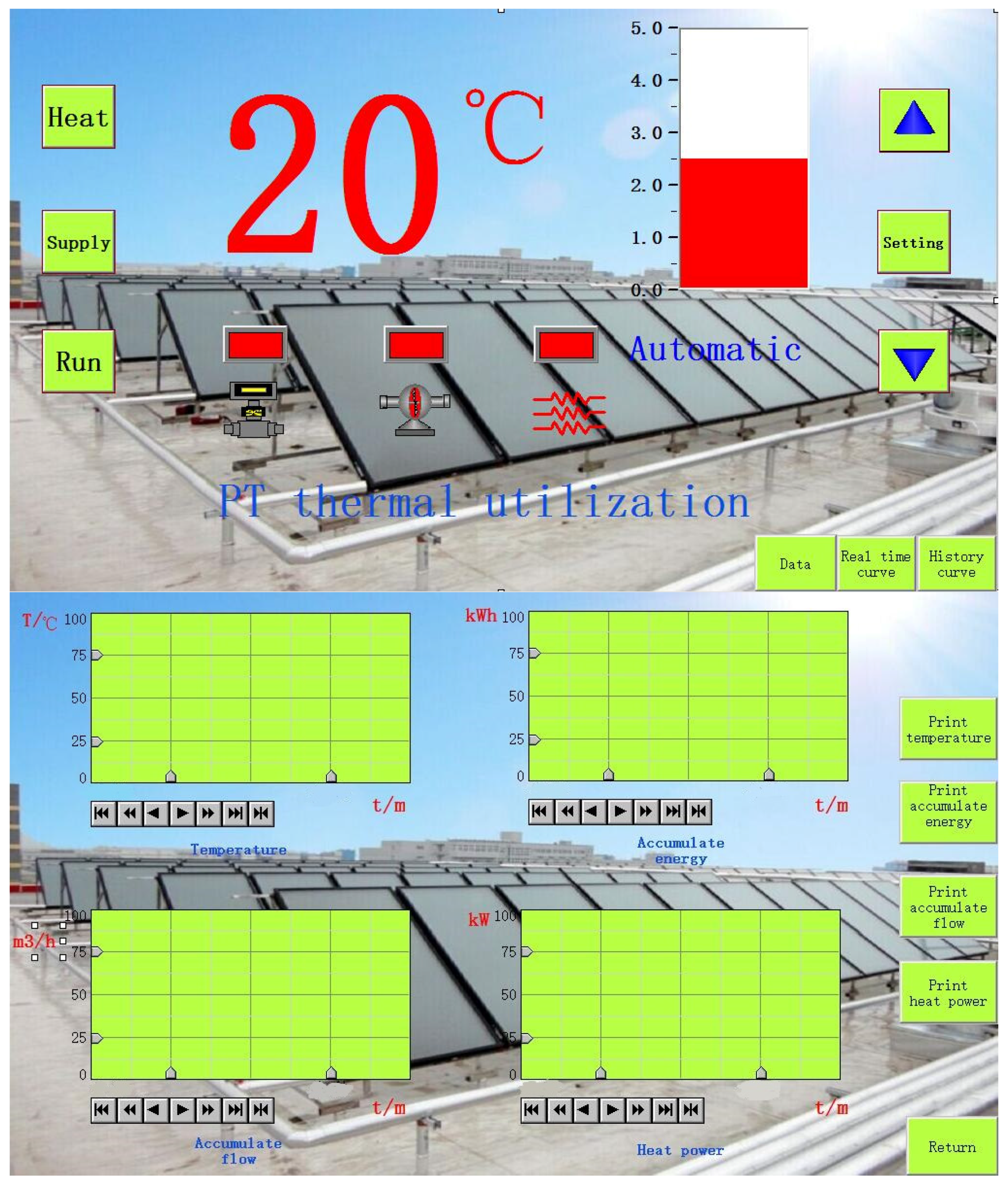
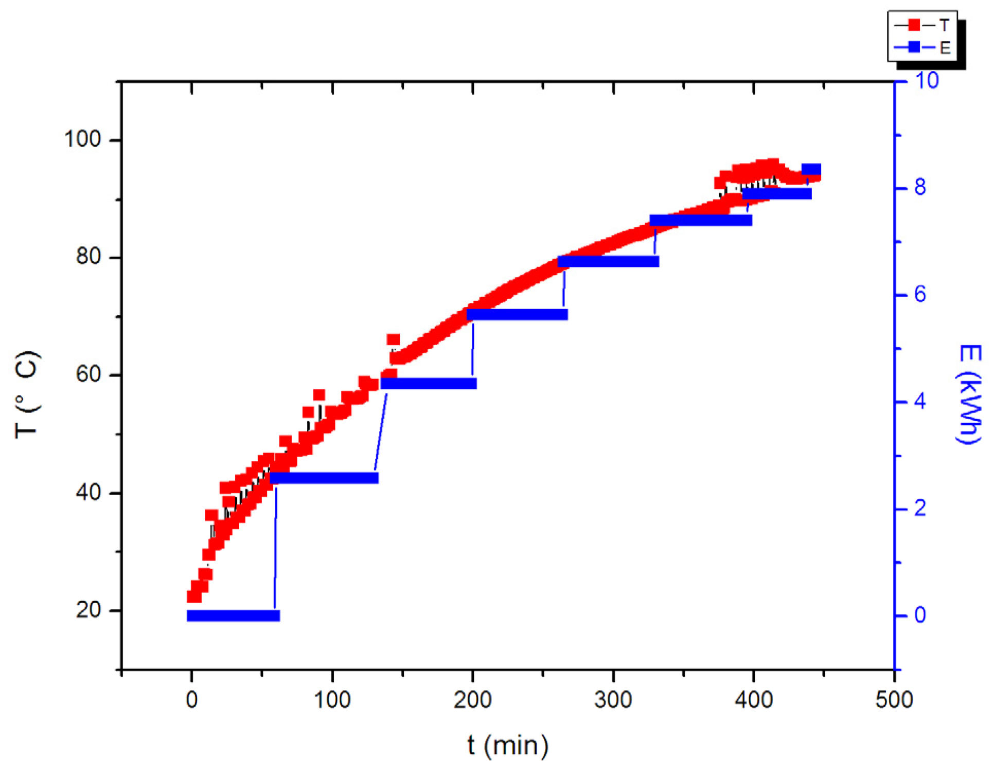
The status of PT thermal utilization can be monitored and controlled. At the same time, the temperature, heat, flow, power, and other parameters of PT thermal utilization can be collected, as shown in Figure 9. The experimental data of PT thermal utilization are shown in Figure 10.
The accumulated thermal energy amount of PT thermal utilization can be calculated according to Equation (3):
where E is the output thermal energy of heat exchange, kWh; t the time of flow accumulation, h; K the heat exchange correction coefficient, J/ (m3·°C); Q the instantaneous rate of water flow, m3/h; and ΔT = the temperature difference between cold water and hot water, °C.
According to the calculation and analysis of Equation (3), the thermal energy of PT thermal utilization is about 3047.8 kWh per year.
5.3. Results Comparison and Analysis
Section 5.1 and Section 5.2 give some results and conclusions about the proposed movable hybrid PVT system. This paper will take the equivalent energy from former work [13] and give some comparisons and discussions between the former work and this work.
In reference [13], the total efficiency η0can be calculated according to Equation (4) for evaluating the hybrid PVT system:
where η0 is the total efficiency, %; ηPV the electric power generation efficiency for PV power generation system, %; and ηPT the heat collection efficiency for PT thermal utilization system, %.
To exactly estimate the efficiency of the hybrid PVT system, this paper proposes and defines a revised equation. The efficiency of the hybrid PVT system can be calculated according to Equation (5):
where Eh is the total efficiency for the hybrid PVT system, %; ηpower is the electric power generation efficiency for a conventional system, %; it usually taken as 0.38 in the recent research [13]; and ηheater is the efficiency of a conventional heating system, %.
For simplicity, the efficiency of conventional heating systems has been assumed to be 100% (namely ηheater = 1). On the basis of experiment data (Section 5.1 and Section 5.2), η0 and Eh can be gained. The results are shown in Table 6.
The results of total efficiency for the proposed movable hybrid PVT system is higher than the previous results [13]. The main reason are as follows:
- the solar flat plate collector and the PV modules placed side by side in the proposed research, but the PV module was adopted to be combined with the solar flat plate collector that formed a stacked structure in the former research;
- their radiated area of the proposed hybrid PVT system equal the area of solar flat plate collector plus the area of PV modules, but their radiated area of the former system equal the area of PV module.
On the basis of these discussions, this paper proposed the area factors SPT and SPV. The modified formula could be shown as Equations (6) and (7):
where SPT is the proportion of their radiated area of solar flat plate collector to the total irradiated area; and SPV the proportion of their radiated area of PV module to the total irradiated area.
The results of the modified equations were shown in the Table 7. The results indicated that Equations (6) and (7) were suitable for all the hybrid PVT system whether solar flat plate collector and PV module have the same irradiated area. The results show that total efficiency for the proposed movable hybrid PVT system is considered lower than the former results [13] at the same time.
These are reasonable results for the proposed study, because the simulated light sources were used in the proposed system. The simulated light sources project not only for the PV modules and solar flat plate collector but also for the other place. Therefore, the efficiency of the proposed movable hybrid PVT system must be lower than the former results slightly.
These results demonstrate that the modified formulae have great significance and value for research on and the application of a hybrid PVT system, especially in the case where the PV module and solar flat plate collector have different irradiated areas.
6. Conclusions
In this paper, the design of and research on the movable hybrid PVT system are presented. The experimental results show that PV power generation can generate 691 kWh of electricity per year and PT thermal utilization can generate 3047.8 kWh of thermal energy per year. This paper also presents a comparison between the proposed results and the former results. The efficiency of the proposed movable hybrid PVT system (42.82%) is only a little lower than the former results due to the simulated light sources applied to the proposed system. The modified formula has been given for the hybrid PVT system and can be used to evaluate the efficiency of the hybrid PVT system at the same time.
Consequently, the system is mainly used for the following two aspects: First, PV power generation can supply DC 24 V that is used for PT thermal utilization and to power the system itself. This means that the system can be widely used in remote areas with no grid connection and but where there are good sunlight conditions to meet the daily hot water and electricity supply. Second, the system equipped with the removable simulated light sources and rolling wheels can satisfy the experimental training of new energy related professionals and achieve the simulation and actual PVT test results in outdoor and indoor conditions.
This research confirms that the application of the movable hybrid PVT system is a feasible and energy efficient way to improve the energy utilization performance of renewable systems.
Acknowledgments
This research was supported by the Tianjin Education Science “The 13th Five-year” Program Project “Research on the cultivation of systematic talents of the energy specialty” (Project No. VEYP5040) and the Science and Technology Program Project of Jin Nan District Tianjin.
Author Contributions
All the authors significantly contributed to the editing and improvement of the manuscript. Lian Zhang conceived and designed the movable hybrid photovoltaic-thermal (PVT) system. Zijian Chen performed the experiments. All the authors analyzed the data. Lian Zhang wrote the paper.
Conflicts of Interest
The authors declare no conflict of interest.
References
- Rittner, E.S. Photovoltaic Device. U.S. Patent 2,873,303, 10 February 1959. [Google Scholar]
- Coxon, D.W.; Gates, T.P. Solar Heat Air System. U.S. Patent 4,203,424, 20 May 1980. [Google Scholar]
- Xiong, Z.P.; Walsh, T.M. PV module durability testing under high voltage biased damp heat conditions. Energy Procedia 2011, 8, 384–389. [Google Scholar] [CrossRef]
- Khoo, Y.S.; Nobre, A. Optimal orientation and tilt angle for maximizing in-plane solar irradiation for PV applications in Singapore. IEEE J. Photovolt. 2014, 4, 647–653. [Google Scholar] [CrossRef]
- Gang, L.I.; Shrotriya, V.; Huang, J.; Yao, Y.; Moriarty, T.; Emery, K.; Yang, Y. High-efficiency solution processable polymer photovoltaic cells by self-organization of polymer blends. Nat. Mater. 2015, 4, 864–868. [Google Scholar]
- Lu, J.F.; Ding, J.; Yang, J. Heat transfer performance and exergetic optimization for solar receiver pipe. Renew. Energy 2010, 35, 1477–1483. [Google Scholar]
- Lin, C.S.; Lin, M.L.; Liou, S.R.; Shei, H.J.; Su, W.P. Development and applications of a fuzzy controller for a forced circulation solar water heater system. J. Sci. Ind. Res. 2010, 69, 537–542. [Google Scholar]
- Zhang, L.; Zhang, Y.F. Research on energy saving potential for dedicated ventilation systems based on heat recovery technology. Energies 2014, 7, 4261–4280. [Google Scholar] [CrossRef]
- Zhang, L.; Zhang, Y.F. Research on heat recovery technology for reducing the energy consumption of dedicated ventilation systems: An application to the operating model of a laboratory. Energies 2016, 9, 24. [Google Scholar] [CrossRef]
- Kamel, R.S.; Fung, A.S.; Dash, P.R.H. Solar systems and their integration with heat pumps: A review. Energy Build. 2015, 87, 395–412. [Google Scholar] [CrossRef]
- Joshi, A.S.; Dincer, I.; Reddy, B.V. Analysis of energy and exergy efficiencies for hybrid PV/T systems. Int. J. Low Carbon Technol. 2011, 6, 64–69. [Google Scholar] [CrossRef]
- Zhang, X.; Zhao, X.; Smith, S. Review of R&D progress and practical application of the solar photovoltaic/thermal (PV/T) technologies. Renew. Sustain. Energy Rev. 2012, 16, 599–617. [Google Scholar]
- Huang, B.J.; Lin, T.H.; Hung, W.C.; Sun, F.S. Performance evaluation of solar photovoltaic/thermal systems. Sol. Energy 2001, 70, 443–448. [Google Scholar] [CrossRef]
- Prompinit, K.; Plangklang, B.; Hiranvarodom, S. Design and construction of a mobile PV hybrid system prototype for isolated electrification. Procedia Eng. 2011, 8, 138–145. [Google Scholar] [CrossRef]
- Eroglu, M.; Dursun, E.; Sevencan, S. A mobile renewable house using PV/wind/fuel cell hybrid power system. Fuel Energy Abstr. 2011, 36, 7985–7992. [Google Scholar] [CrossRef]
Figure 1.
The appearance structure: (a) front view; (b) back view; (c) sectional view A; (d) sectional view B; and (e) bottom view.
Figure 1.
The appearance structure: (a) front view; (b) back view; (c) sectional view A; (d) sectional view B; and (e) bottom view.

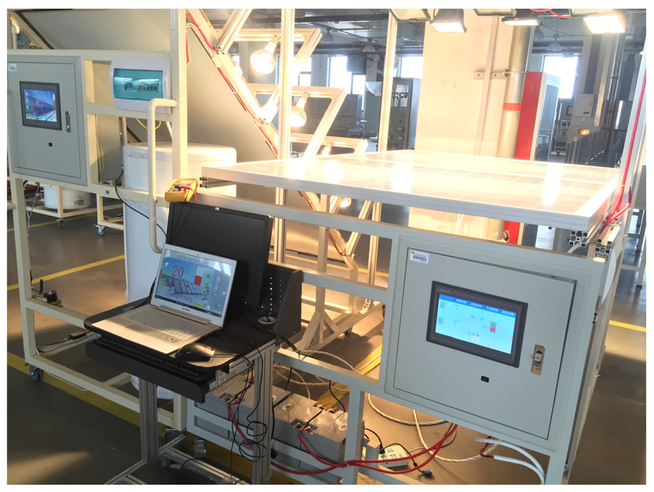
Figure 2.
A photograph of the proposed system.

Figure 3.
The energy flow of photovoltaic power generation.

Figure 4.
The energy flow of PT thermal utilization.
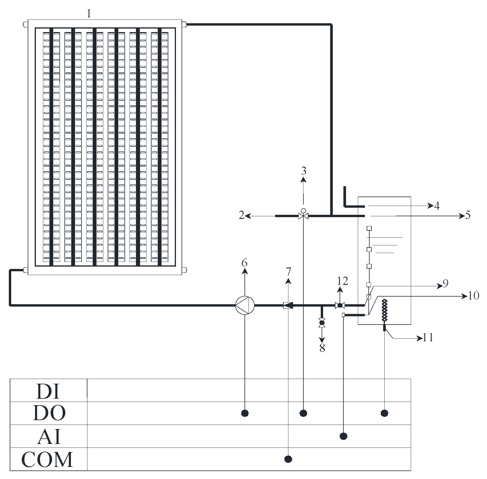
Figure 5.
The control circuit of PV power generation.

Figure 6.
The control circuit of PT thermal utilization.

Figure 7.
The interfaces of monitoring and parameter adjustment of PV power generation.

Figure 8.
The V-I characteristic curve and the power output curve of PV power generation.

Figure 9.
The interfaces of monitoring and data acquisition of PT thermal utilization.

Figure 10.
The temperature and heat curve of PT thermal utilization (The temperature curve refers to the water temperature of the collector; the heat meter collect the data once an hour in the experimental test, so there were straight lines when the heat meter had not collected data).
Figure 10.
The temperature and heat curve of PT thermal utilization (The temperature curve refers to the water temperature of the collector; the heat meter collect the data once an hour in the experimental test, so there were straight lines when the heat meter had not collected data).


Table 1.
The components according to the Figure 1.
Table 1.
The components according to the Figure 1.
| Labels According to the Figure 1 | Components | Labels According to the Figure 1 | Components |
|---|---|---|---|
| 1 | Solar flat plate collector | 2 | Simulated light sources |
| 3 | Left moving frame | 4 | Water tank |
| 5 | Rolling wheels | 6 | Control cabinet of photo-thermal (PT) thermal utilization |
| 7 | Touch screen of PT thermal utilization | 8 | Switch box of PT thermal utilization |
| 9 | Touch screen switch of PT thermal utilization | 10 | Horizontal support bar of photovoltaic (PV) power generation |
| 11 | Right moving frame | 12 | PV modules |
| 13 | Rotary bar of PV power generation | 14 | Cross-bar of PV power generation |
| 15 | Control cabinet of PV power generation | 16 | Support frame of simulated light sources |
| 17 | Vertical support bar of PV power generation | 18 | Batteries |
| 19 | Touch screen of PV power generation | 20 | Switch box of PV power generation |
| 21 | Protractor | 22 | Adjustment bracket of PV power generation |
| 23 | Touch screen switch of PV power generation | - | - |
Table 2.
The components according to the Figure 3.
Table 2.
The components according to the Figure 3.
| Labels According to the Figure 3 | Components | Labels According to the Figure 3 | Components |
|---|---|---|---|
| 1 | PV modules | 2 | Inverter |
| 3 | Switches | 4 | Relays |
| 5 | Batteries | 6 | Fuses |
Table 3.
The components according to the Figure 4.
Table 3.
The components according to the Figure 4.
| Labels According to the Figure 4 | Components | Labels According to the Figure 4 | Components |
|---|---|---|---|
| 1 | Solar flat plate collector | 2 | External water source |
| 3 | Electromagnetic valve | 4 | Exhaust port |
| 5 | Water inlet | 6 | DC water pump |
| 7 | Ultrasonic heat meter | 8 | Drainage terminal |
| 9 | Water outlet | 10 | Liquid level sensor |
| 11 | Electric auxiliary heater | 12 | Manual valve |
| DI | Digital input port of the I/O board | DO | Digital output port of the I/O board |
| AI | Analog input port of the I/O board | COM | Serial communication ports of the I/O board |
Table 4.
The components according to the Figure 5.
Table 4.
The components according to the Figure 5.
| Labels According to the Figure 5 | Components | Labels According to the Figure 5 | Components |
|---|---|---|---|
| 1 | PV modules | 2 | Inverter |
| 3 | Switches | 4 | DC current sensor I |
| 5 | DC current sensor II | 6 | Relay(the output of the PV module) |
| 7 | Relay(the output of the PV module) | 8 | Relay(the input of the inverter) |
| 9 | I/O board | 10 | Batteries |
| 11 | Touch screen | 12 | Loads |
| 13 | Touch screen switch | 14 | Fuse I(the input of the inverter) |
| 15 | Fuse II (the output of the inverter) | 16 | Diodes |
Table 5.
The components according to the Figure 6.
Table 5.
The components according to the Figure 6.
| Labels According to the Figure 6 | Components | Labels According to the Figure 6 | Components |
|---|---|---|---|
| 1 | DC water pump | 2 | Electromagnetic valve |
| 3 | Ultrasonic heat meter | 4 | Liquid level sensor |
| 5 | Electric auxiliary heater | 6 | Rectifier |
| 7 | Transformer | 8 | Switches |
| 9 | AC contactor | 10 | Pilot lamp |
| 11 | Relay(DC water pump) | 12 | Relay(electromagnetic valve) |
| 13 | Conversion module | 14 | I/O board |
| 15 | Touch screen | 16 | Touch screen switch |
| 17 | Diode | - | - |
Table 6.
Efficiency of the proposed movable hybrid PVT system.
| Parameters of the System | Results |
|---|---|
| The power of the simulated light sources in PV system (kW) | 2 |
| The power of the simulated light sources in PT system (kW) | 2 |
| The power generation of PV system yearly (kWh) | 691 |
| The heat generation of PT system yearly (kWh) | 3047.8 |
| ηPV (%) | 11.83 |
| ηPT (%) | 52.19 |
| η0 (%) | 64.02 |
| Eh (%) | 83.32 |
Table 7.
Efficiency of the proposed movable hybrid photovoltaic-thermal (PVT) system using the modified equations.
Table 7.
Efficiency of the proposed movable hybrid photovoltaic-thermal (PVT) system using the modified equations.
| Parameters of the System | Results |
|---|---|
| The power of the simulated light sources in PV system (kW) | 2 |
| The power of the simulated light sources in PT system (kW) | 2 |
| The power generation of PV system yearly (kWh) | 691 |
| The heat generation of PT system yearly (kWh) | 3047.8 |
| ηPV (%) | 11.83 |
| ηPT (%) | 52.19 |
| η0 (%) | 34.23 |
| Eh (%) | 42.82 |
© 2017 by the authors. Licensee MDPI, Basel, Switzerland. This article is an open access article distributed under the terms and conditions of the Creative Commons Attribution (CC BY) license (http://creativecommons.org/licenses/by/4.0/).
Share and Cite
MDPI and ACS Style
Zhang, L.; Chen, Z.J. Design and Research of the Movable Hybrid Photovoltaic-Thermal (PVT) System. Energies 2017, 10, 507. https://doi.org/10.3390/en10040507
AMA Style
Zhang L, Chen ZJ. Design and Research of the Movable Hybrid Photovoltaic-Thermal (PVT) System. Energies. 2017; 10(4):507. https://doi.org/10.3390/en10040507
Chicago/Turabian StyleZhang, Lian, and Zi Jian Chen. 2017. "Design and Research of the Movable Hybrid Photovoltaic-Thermal (PVT) System" Energies 10, no. 4: 507. https://doi.org/10.3390/en10040507
Note that from the first issue of 2016, this journal uses article numbers instead of page numbers. See further details here.