
Low Temperature Aqueous Solution-Processed ZnO and Polyethylenimine Ethoxylated Cathode Buffer Bilayer for High Performance Flexible Inverted Organic Solar Cells

 ,
,
Abstract
:1. Introduction
2. Results and Discussion
3. Materials and Methods
3.1. Preparation of Materials
3.2. Fabrication and Measurement of Flexible Organic Solar Cells
4. Conclusions
Acknowledgments
Author Contributions
Conflicts of Interest
References
- Baek, W.H.; Seo, I.; Yoon, T.S.; Lee, H.H.; Yun, C.M.; Kim, Y.S. Hybrid inverted bulk heterojunction solar cells with nanoimprinted TiO2 nanopores. Sol. Energy Mater. Sol. Cells 2009, 93, 1587–1591. [Google Scholar] [CrossRef]
- Wang, J.C.; Weng, W.T.; Tsai, M.Y.; Lee, M.K.; Horng, S.F.; Perng, T.P.; Kei, C.C.; Yu, C.C.; Meng, H.F. Highly efficient flexible inverted organic solar cells using atomic layer deposited ZnO as electron selective layer. J. Mater. Chem. 2010, 20, 862–866. [Google Scholar] [CrossRef]
- Zhang, F.; Xu, X.; Tang, W.; Zhang, J.; Zhuo, Z.; Wang, J.; Wang, J.; Xu, Z.; Wang, Y. Recent development of the inverted configureuration organic solar cells. Sol. Energy Mater. Sol. Cells 2011, 95, 1785–1799. [Google Scholar] [CrossRef]
- Huang, J.S.; Chou, C.Y.; Liu, M.Y.; Tsai, K.H.; Lin, W.H.; Lin, C.F. Solution-processed vanadium oxide as an anode interlayer for inverted polymer solar cells hybridized with ZnO nanorods. Org. Electron. 2009, 10, 1060–1065. [Google Scholar] [CrossRef]
- Ye, L.; Zhao, W.; Li, S.; Mukherjee, S.; Carpenter, J.H.; Awartani, O.; Jiao, X.; Hou, J.; Ade, H. High-efficiency nonfullerene organic solar cells: Critical factors that affect complex multi-length scale morphology and device performance. Adv. Energy Mater. 2016. [Google Scholar] [CrossRef]
- Zhang, S.; Ye, L.; Hou, J. Breaking the 10% efficiency barrier in organic photovoltaics: Morphology and Device optimization of well-known PBDTTT polymers. Adv. Energy Mater. 2016, 6, 1502529. [Google Scholar] [CrossRef]
- Huang, J.; Li, C.Z.; Chueh, C.C.; Liu, S.Q.; Yu, J.S.; Jen, A.K.Y. 10.4% Power conversion efficiency of ITO-free organic photovoltaics through enhanced light trapping configureuration. Adv. Energy Mater. 2015, 5. [Google Scholar] [CrossRef]
- Jørgensen, M.; Norrman, K.; Gevorgyan, S.A.; Tromholt, T.; Andreasen, B.; Krebs, F.C. Stability of polymer solar cells. Adv. Mater. 2012, 24, 580–612. [Google Scholar] [CrossRef] [PubMed]
- Min, J.; Luponosov, Y.N.; Zhang, Z.G.; Ponomarenko, S.A.; Ameri, T.; Li, Y.; Brabec, C.J. Interface design to improve the performance and stability of solution-processed small-molecule conventional solar cells. Adv. Energy Mater. 2014, 4, 1400816. [Google Scholar] [CrossRef]
- Chen, D.; Zhang, C.; Heng, T.; Wei, W.; Wang, Z.; Han, G.; Feng, Q.; Hao, Y.; Zhang, J. Efficient inverted polymer solar cells using low-temperature zinc oxide interlayer processed from aqueous solution. Jpn. J. Appl. Phys. 2015, 54, 042301. [Google Scholar] [CrossRef]
- Savagatrup, S.; Printz, A.D.; O’Connor, T.F.; Zaretski, A.V.; Rodriquez, D.; Sawyer, E.J.; Rajan, K.M.; Acosta, R.I.; Root, S.E.; Lipomi, D.J. Mechanical degradation and stability of organic solar cells: Molecular and microstructural determinants. Energy Environ. Sci. 2015, 8, 55–80. [Google Scholar] [CrossRef]
- Pachoumi, O.; Li, C.; Vaynzof, Y.; Bange, K.K.; Sirrintghaus, H. Improved performance and stability of inverted organic solar cells with sol-gel processed, amorphous mixed metal oxide electron extraction layers comprising alkaline earth metals. Adv. Energy Mater. 2013, 3, 1428–1436. [Google Scholar] [CrossRef]
- Chen, D.; Zhang, C.; Wei, W.; Wang, Z.; Heng, T.; Tang, S.; Han, G.; Zhang, J.; Hao, Y. Stability of inverted organic solar cells with low—Temperature ZnO buffer layer processed from aqueous solution. Phys. Status Solidi A 2015, 212, 2262–2270. [Google Scholar] [CrossRef]
- Zhang, C.; You, H.; Lin, Z.; Hao, Y. Inverted organic photovoltaic cells with solution-processed zinc oxide as electron collecting layer. Jpn. J. Appl. Phys. 2011, 50, 082302. [Google Scholar] [CrossRef]
- Lin, Z.; Jiang, C.; Zhu, C.; Zhang, J. Development of inverted organic solar cells with TiO2 interface layer by using low-temperature atomic layer deposition. ACS. Appl. Mater. Interfaces 2013, 5, 713–718. [Google Scholar] [CrossRef] [PubMed]
- Lin, Z.; Chang, J.; Zhang, J.; Jiang, C.; Wu, J.; Zhu, C. A work-function tunable polyelectrolyte complex (PEI:PSS) as a cathode interfacial layer for inverted organic solar cells. J. Mater. Chem. A. 2014, 2, 7788–7794. [Google Scholar] [CrossRef]
- Chang, J.; Lin, Z.; Jiang, C.; Zhang, J.; Zhu, C.; Wu, J. Improve the operational stability of the inverted organic solar cells using bilayer metal oxide structure. ACS Appl. Mater. Interfaces 2014, 6, 18861–18867. [Google Scholar] [CrossRef] [PubMed]
- Wang, W.; Schaffer, C.J.; Song, L.; Körstgens, V.; Pröller, S.; Indari, E.D.; Wang, T.; Abdelsamie, A.; Bernstorff, S.; Müller-Buschbaum, P. In operando morphology investigation of inverted bulk heterojunction organic solar cells by GISAXS. J. Mater. Chem. A 2015, 3, 8324–8331. [Google Scholar] [CrossRef]
- Wang, W.; Pröller, S.; Niedermeier, M.A.; Körstgens, V.; Philipp, M.; Su, B.; González, D.M.; Yu, S.; Roth, S.V.; Müller-Buschbaum, P. Development of the morphology during functional stack build-up of P3HT:PCBM bulk heterojunction solar cells with inverted geometry. ACS. Appl. Mater. Interfaces 2014, 7, 602–610. [Google Scholar] [CrossRef] [PubMed]
- Wei, W.; Zhang, C.; Chen, D.; Wang, Z.; Zhu, C.; Zhang, J.; Lu, X.; Hao, Y. Efficient “light-soaking”-free inverted organic solar cells with aqueous solution processed low-temperature zno electron extraction layers. ACS. Appl. Mater. Interfaces 2013, 5, 13318–13324. [Google Scholar] [CrossRef] [PubMed]
- Li, P.; Cai, L.; Wang, G.; Xiang, J.; Zhang, Y.J.; Ding, B.F.; Alameh, K.; Song, Q.L. PEIE capped ZnO as cathode buffer layer with enhanced charge transfer ability for high efficiency polymer solar cells. Synthet. Met. 2015, 203, 243–248. [Google Scholar] [CrossRef]
- Courtright, B.A.E.; Jenekhe, S.A. Polyethylenimine interfacial layers in inverted organic photovoltaic devices: Effects of ethoxylation and molecular weight on efficiency and temporal stability. ACS. Appl. Mater. Interfaces 2015, 7, 26167–26175. [Google Scholar] [CrossRef] [PubMed]
- Bai, S.; Wu, Z.; Xu, X.; Jin, Y.; Sun, B.; Guo, X.; He, S.; Wang, X.; Ye, Z.; Wei, H.; et al. Inverted organic solar cells based on aqueous processed ZnO interlayers at low temperature. Appl. Phys. Lett. 2012, 100, 203906. [Google Scholar] [CrossRef]
- You, H.; Zhang, J.; Zhang, C.; Lin, Z.; Chen, D.; Chang, J.; Zhang, J. Efficient flexible inverted small-bandgap organic solar cells with low-temperature zinc oxide interlayer. Jpn. J. Appl. Phys. 2016, 55, 122302. [Google Scholar] [CrossRef]
- Ka, Y.; Lee, E.; Park, S.Y.; Seo, J.; Kwon, D.G.; Lee, H.H.; Park, Y.; Kim, Y.S.; Kim, C. Effects of annealing temperature of aqueous solution-processed ZnO electron-selective layers on inverted polymer solar cells. Org. Electron. 2013, 14, 100–104. [Google Scholar] [CrossRef]
- Zhang, C.; Zhang, J.; Hao, Y.; Lin, Z.; Zhu, C. A simple and efficient solar cell parameter extraction method from a single current-voltage curve. J. Appl. Phys. 2011, 110, 064504. [Google Scholar] [CrossRef]
- Li, P.; Wang, G.; Cai, L.; Ding, B.; Zhou, D.; Hu, Y.; Zhang, Y.; Xiang, J.; Wan, K.; Chen, L.; et al. High-efficiency inverted polymer solar cells controlled by the thickness of polyethylenimine ethoxylated (PEIE) interfacial layers. Phys. Chem. Chem. Phys. 2014, 16, 23792–23799. [Google Scholar] [CrossRef] [PubMed]
- Hu, T.; Li, L.; Xiao, S.; Yuan, K.; Yang, H.; Chen, L.; Chen, Y. In situ implanting carbon nanotube-gold nanoparticles into ZnO as efficient nanohybrid cathode buffer layer for polymer solar cells. Org. Electron. 2016, 38, 350–356. [Google Scholar] [CrossRef]
- Lee, T.H.; Choi, H.; Walker, B.; Kim, T.; Kim, H.B.; Kim, J.Y. Replacing the metal oxide layer with a polymer surface modifier for high-performance inverted polymer solar cells. RSC. Adv. 2014, 4, 4791–4795. [Google Scholar] [CrossRef]
- Ye, L.; Zhou, C.; Meng, H.; Wu, H.H.; Lin, C.C.; Liao, H.H.; Zhang, S.; Hou, J. Toward reliable and accurate evaluation of polymer solar cells based on low band gap polymers. J. Mater. Chem. 2015, 3, 564–569. [Google Scholar] [CrossRef]


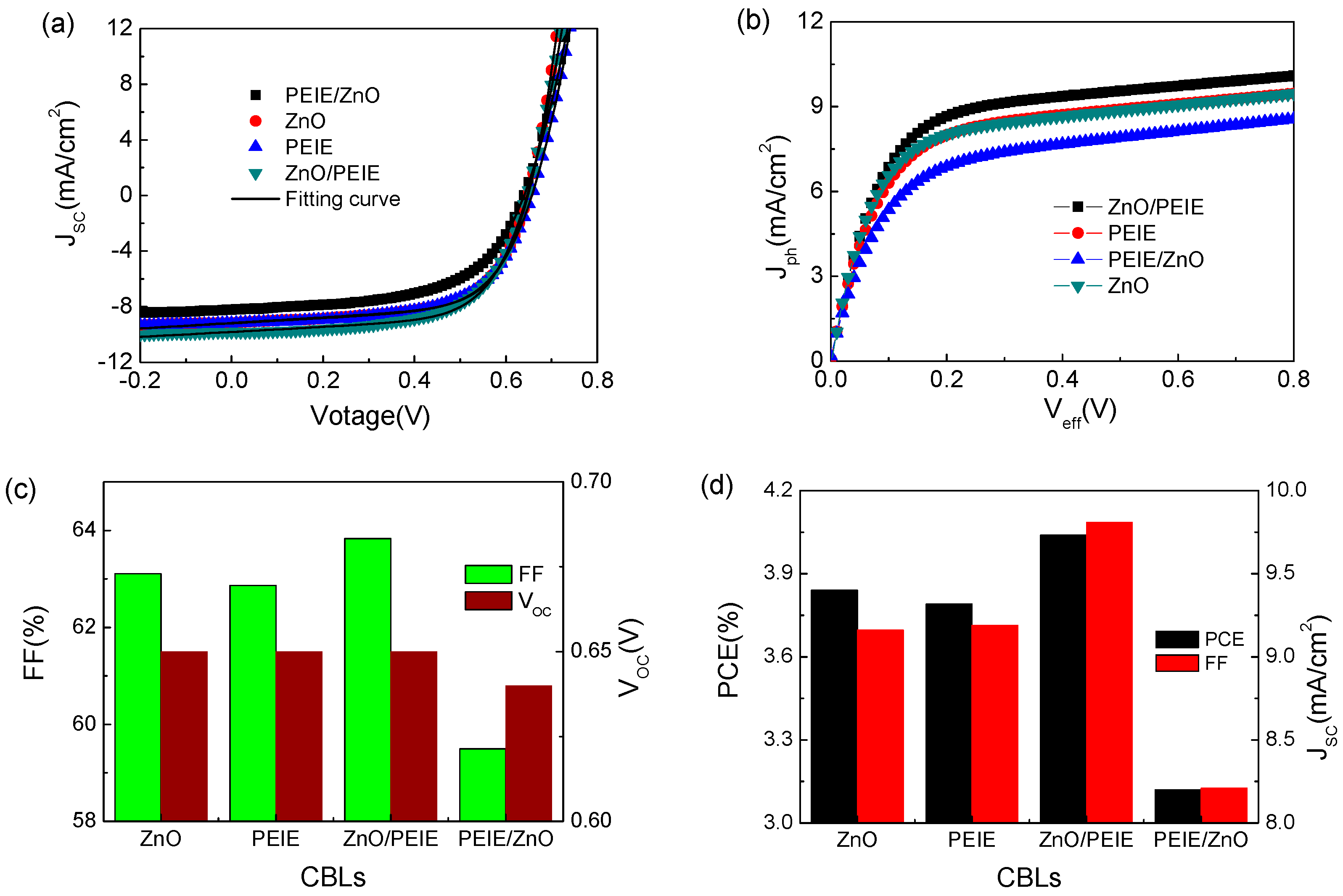
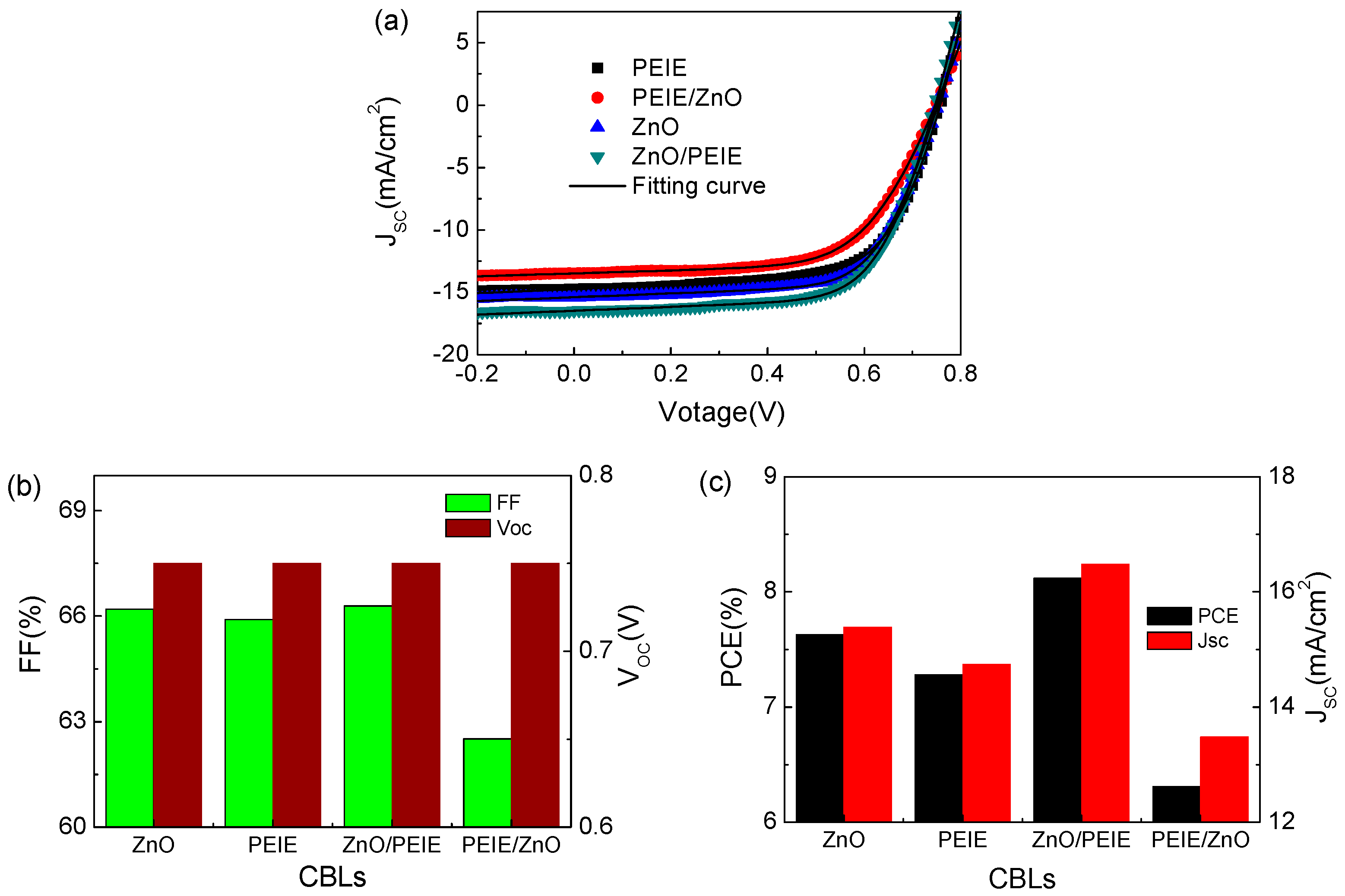
| Active layer | CBLs | JSC (mA/cm2) | VOC (V) | FF (%) | PCE (%) | Rs (Ω/cm2) | Rsh (Ω/cm2) | |
|---|---|---|---|---|---|---|---|---|
| Best | Ave | |||||||
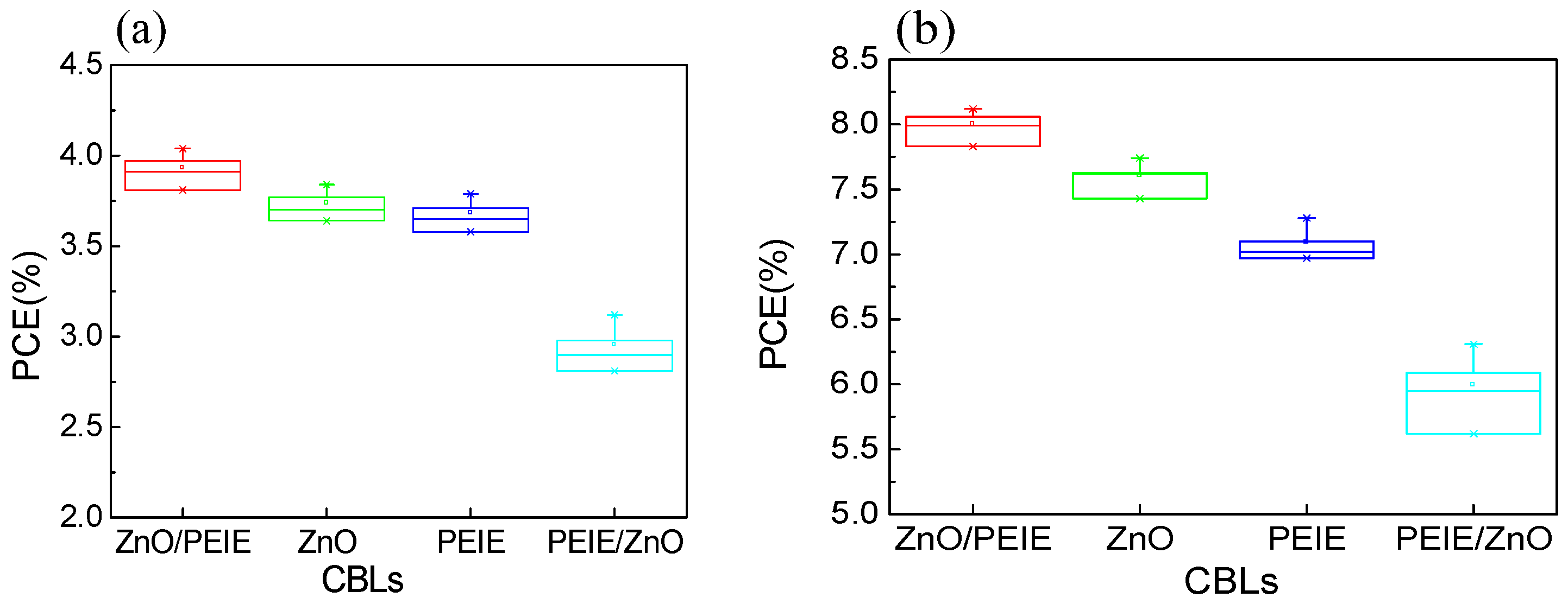
| P3HT:PC61BM | ZnO | 9.16 | 0.65 | 63.61 | 3.84 | 3.74 | 2.1 | 501.8 |
| PEIE | 9.19 | 0.65 | 62.87 | 3.79 | 3.68 | 3.1 | 473.9 | |
| ZnO/PEIE | 9.81 | 0.65 | 63.83 | 4.04 | 3.93 | 2.7 | 479.7 | |
| PEIE/ZnO | 8.21 | 0.64 | 58.98 | 3.12 | 2.95 | 3.2 | 449.8 | |
| PTB-7:PC71BM | ZnO | 15.39 | 0.75 | 65.91 | 7.63 | 7.59 | 4.9 | 610.5 |
| PEIE | 14.74 | 0.75 | 65.32 | 7.28 | 7.09 | 5.6 | 594.3 | |
| ZnO/PEIE | 16.48 | 0.75 | 66.01 | 8.12 | 8.00 | 4.1 | 645.1 | |
| PEIE/ZnO | 13.48 | 0.75 | 62.14 | 6.31 | 5.99 | 6.4 | 757.9 | |
© 2017 by the authors. Licensee MDPI, Basel, Switzerland. This article is an open access article distributed under the terms and conditions of the Creative Commons Attribution (CC BY) license (http://creativecommons.org/licenses/by/4.0/).
Share and Cite
You, H.; Zhang, J.; Zhang, Z.; Zhang, C.; Lin, Z.; Chang, J.; Han, G.; Zhang, J.; Lu, G.; Hao, Y. Low Temperature Aqueous Solution-Processed ZnO and Polyethylenimine Ethoxylated Cathode Buffer Bilayer for High Performance Flexible Inverted Organic Solar Cells. Energies 2017, 10, 494. https://doi.org/10.3390/en10040494
You H, Zhang J, Zhang Z, Zhang C, Lin Z, Chang J, Han G, Zhang J, Lu G, Hao Y. Low Temperature Aqueous Solution-Processed ZnO and Polyethylenimine Ethoxylated Cathode Buffer Bilayer for High Performance Flexible Inverted Organic Solar Cells. Energies. 2017; 10(4):494. https://doi.org/10.3390/en10040494
Chicago/Turabian StyleYou, Hailong, Junchi Zhang, Zeyulin Zhang, Chunfu Zhang, Zhenhua Lin, Jingjing Chang, Genquan Han, Jincheng Zhang, Gang Lu, and Yue Hao. 2017. "Low Temperature Aqueous Solution-Processed ZnO and Polyethylenimine Ethoxylated Cathode Buffer Bilayer for High Performance Flexible Inverted Organic Solar Cells" Energies 10, no. 4: 494. https://doi.org/10.3390/en10040494