A Novel Optimal Control Method for Islanded Microgrids Based on Droop Control Using the ICA-GA Algorithm


Electrical and Electronic Engineering Department, Shahed University, 3319118651 Tehran, Iran
*
Author to whom correspondence should be addressed.
Energies 2017, 10(4), 485; https://doi.org/10.3390/en10040485
Submission received: 4 March 2017
/
Revised: 26 March 2017
/
Accepted: 31 March 2017
/
Published: 4 April 2017
(This article belongs to the Special Issue Advanced Operation and Control of Smart Microgrids)
Abstract
:Microgrids are small scale power systems with local resources for generation; consumption and storage, that can operate connected to the main grid or islanded. For the islanding operation of microgrids, two important tasks are to share the load demand and maintain the voltage and frequency stabilities. In order to achieve this goal, a hierarchical control structure can be employed. This research presents a solution technique for finding the optimal site, production and droop coefficients of distributed generation (DG) units in microgrids. In this paper, three main factors are scrutinized through a multi-objective optimization approach. These factors include fuel consumption cost, stability and variations of voltage. To solve this optimization problem, an Imperialist Competitive Algorithm-Genetic Algorithm (ICA-GA) is presented. A fuzzy approach is used to search in non-dominated outcomes and to find the best answer. To show the effectiveness of the proposed method, it is implemented on 33-buses IEEE test systems. The simulation results exhibit the ability and efficiency of the proposed scheme to find the optimal solutions.
1. Introduction
In microgrids (MGs), due to their scalability, competitive investment costs and flexible operation, fossil-fuel generation technologies have been the most common choice for supply of electricity in these remote networks. However, green energy such as wind, hydrogen and solar with economic and technical possibility, has become a preference in MGs [1]. MGs are remarkable and necessary parts of distribution system development [2]. MGs can be explained as distributed generation (DG) units, flexible loads and storages that operate in a balanced way to reliably generate power, connected to the main grid at the distribution level at a single coupling point, the so-called Point of Common Coupling (PCC) [1]. The MG can operate in autonomous (islanded), or connected mode.
Siting and operation of DGs are special topics in distribution network optimization papers that must consider the miscellaneous factors that affect the action of MGs. A detailed definition of optimal placement and production of DG units in a MG is still a topic of discussion [3,4,5,6,7,8], and studies are still ongoing as to what is the optimal operation of DGs.
To find the optimal operation of the islanded MG with and without droop control the use of a central controller (CC) is vital. An MG CC is a solution for which some researchers have put forward models for the improvement of the operation of autonomous MGs. By focusing on economic profits, optimum scheduling techniques for autonomous MGs are discussed in [9]. Zoka and Vasiljevska and their colleagues, had utilized the microgrid central controller (MG CC) to optimize the total fuel cost of islanded MGs where DGs are modeled based on droop control and a combined heat and power (CHP) unit [10,11].
The research of [12] looked at power dispatching among DGs using an evolutionary algorithm. To reduce the fuel cost of islanded MGs, different techniques are proposed [12,13]. The authors in [14], used the Harmony Search-Genetic Algorithm (HS-GA) for optimal operation of autonomous MG, but this paper considered only operation, not optimal location. In [15,16], an analytical programming method is given for sharing reactive power among DGs using droop control and considering the uncertainty of small wind plants. To find the optimal combination of DGs among micro-turbines, photovoltaics, and storages to supply thermal and power demands for a small MG, a dynamic programming method is employed. In [17] a combination of DGs is explained by utilizing a linear programming scheme. To optimize the system operation where some agents can generate scheduling models from MG information, a multi-agent system for MG management is proposed in [18]. Operation optimization of DGs is expressed in [19] considering environmental factors. Using a hybrid evolutionary approach in a connected mode MG, optimal placement and operation of DGs in MGs are given [20,21].
Load flow analysis of a power system involves computing the voltage of all the buses and the active and reactive power flow through lines of a given load profile. A number of studies have proposed different power flow analysis models to address the characteristics of distribution systems and microgrids, including high R/X ratios (ratio of resistance of the line and reactance of the line), radial or weakly meshed topologies and a large number of branches and nodes. Some of the studies are based on the Newton-Raphson method [22,23], while others are based on the Gauss-Siedel method [24,25]. In [26] a method for solving the power flow problem using basic electric circuit laws was introduced.
In [27,28] modified methods to solve the power mismatch equations based on evolutionary algorithms were presented. In [29], authors presented an improved evolutionary algorithm for load flow analysis in island MGs and test system is a 6-bus microgrid system, although this system is very small. Load flow analysis in an islanded MG with renewable energy sources has been studied using the Guaranteed convergence Particle Swarm Optimization with Gaussian Mutation (GPSO-GM) method in [30].
In [31] a new model of low voltage (LV) distribution systems with distributed energy resources (DER) has been proposed, which is suitable for aggregating an existing distribution system into a cluster of virtual microgrids. The model is based on a linearized formulation of the branch flow equations and of the medium voltage/low voltage (MV/LV) supplying system.
The mentioned studies represent a major portion in the field of electricity network optimization, but a review of works indicates that studies that have paid attention to the optimal operation of DGs along with their optimal location are scarce. This paper tries to compensate for this shortfall. It presents a new hybrid optimization algorithm to simultaneously find and choose the optimal operation mode and DG placement of an islanded MG. By looking for the optimal droop gain parameters of DGs and finding those, the operation is optimized. Three main factors are formulated through a multi-objective optimization problem. These factors include minimizing the fuel consumption cost, improving the stability and voltage variations subject to considering of operation and security constraints. To solve the multi-objective optimization problem in this work, a new hybrid algorithm, Imperialist Competitive Algorithm-Genetic Algorithm (ICA-GA), is developed. To run the suggested algorithm a novel formulation of load flow is utilized based on droop control, where the optimization variables include the steady state frequency of the system, reference voltage, reference frequency and droop parameters of DGs. In the suggested technique, the Pareto front of non-dominated results is provided, next the best answer of non-dominated outcomes are obtained by using a fuzzy approach.
The rest of this paper is structured as follows: firstly, the paper gives the problem formulation. This is followed by developing the proposed algorithm followed by providing a heuristic method to solve the optimization problem. Finally, simulation results and discussion are given.
2. Problem Formulation
The problem in this article is how to find the optimal place and static characteristics of DG units to: (1) reduce fuel consumption cost (f1); (2) improve voltage stability (f2); and (3) reduce variations of voltage (f3), subject to some constraints. This minimization problem with above three objective functions can be formulated by the following expression:
where k and i indicate DGs place and static characteristics. Static characteristics containing droop parameters, frequency and voltage references:
A. Fuel consumption cost: This index can be expressed by:
B. Voltage Stability Index (VSI): If DG units are connected to a radial distribution system, the voltage stability index is modified. The bus, whose voltage stability index value is poor, is further sensitive to voltage collapse. The equations utilized to formulate this index are proposed in [32] to solve the load flow for distribution networks. The voltage stability index is defined as in Equation (4). By using this voltage stability index, one could measure the level of stability of MGs and thus appropriate action may be taken if the index indicates a poor level of stability. After the voltages at each bus are considered for load flow study, the VSI for all the receiving end buses of radial distribution systems can be calculated with this equation:
Figure 1 shows a MG line that is employed to calculate the stability of the voltage.
The bus, at which the range of the stability index is minimum, is more sensitive to the voltage collapse. The objective function stability index is given by Equation (5):
VSI should be maximized for developing voltage stability as its consequence the presented objective function will be minimized.
C. Variations of Voltage (VV): To uniform voltage in MG, VV index can be given by:
D. Constraints: There are two types of limits in the optimization problem: equality and inequality limits. Load flow equations are equality limits which can be expressed by [14]:
Inequality limits include voltage, thermal and power generation limits:
- (1)
- Voltage: One of the inequality limits is the magnitude of voltage in buses as shown in [14]:
- (2)
- Thermal: The thermal limit is occurred because of the current flow in MG lines:
- (3)
- Power Generation Limit of DGs: For the MG that operates in islanded mode with a droop controller, the power generation limit can be obtained based on active, reactive and nominal power [21]:
3. Proposed Solution
Here, to solve the above multi-objective problem, a new scheme is proposed. The solution is developed in three parts: (a) proposing a hybrid optimization algorithm, named ICA-GA, to solve the multi-objective problem; (b) creating a novel load flow formulation to run suggested algorithm, ICA-GA, that the optimization variables based on droop control, are the steady state frequency of system, reference voltage, reference frequency and droop parameters of DGs; and (c) adopting a fuzzy approach to procure the best answer of non-dominated outcomes.
3.1. Three Fuzzy-Subordination Functions
In this paper for solving the multi-objective problem, three objective functions, and are considered as explained in Equations (3), (5) and (6), respectively. Therefore, to find the multi-objective problem solution, fuzzy functions are used. The objective functions that described in the previous section should be modified by utilizing the following membership functions:
where i = 1, 2, 3; , and are indices for the fuzzy subordination of three optimized objectives. The bounds and , are the best values that calculated from three objective functions. These fuzzy functions are linear-partition of fall half trapezoid that can be seen in Figure 2. Evolutionary algorithms create a random swarm and explore in a problem space to find the optimal answer. In the proposed method to solve multi-objective functions, there is a set of non-dominated answers that can be kept in each iteration in a repository. The answer dominates if Equations (15) and (16) are warranted:
The following equation, named normalized function, can be employed to evaluate each individual that there is in the repository:
Equation (17) can be used for all objective functions to sort the non-dominated responses according to the determiner priority.
3.2. Genetic Algorithm (GA)
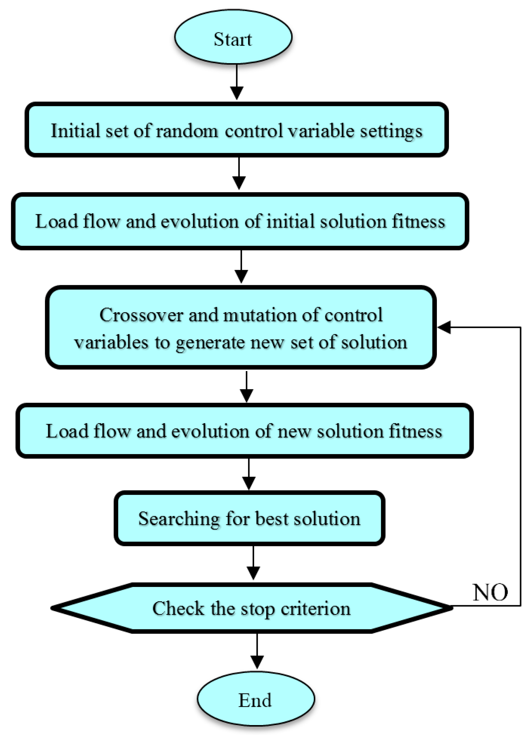
The GA that is applied in our suggested scheme is briefly explained in this section. The population in the GA has n chromosomes that indicate the candidate solutions; the number of optimized variables is m, so that any chromosome is an m dimensional real value vector. Thus, any optimized variable illustrates a dimension of the problem space. Figure 3 shows the flowchart of a GA algorithm for finding optimal site, production and droop parameters of DGs and this algorithm can be explained in the following stages:
- Stage 1:
- First puts the time tally t = 0 and then generates n chromosomes accidentally, [, j = 1,…, n], where = [, ,…, ]. , will generate in searching space [; ] accidentally (initialization).
- Stage 2:
- Creating Jbest (best value of the objective function) after evaluating each member in the initial population (fitness).
- Stage 3:
- Set t = t + 1 (time updating).
- Stage 4:
- By iterating the following stages makes a new population until the new population is perfected: (new population):Selection: choosing parents with considering their fitness.Crossover: to create a new child can cross over the parents with a crossover possibility.Mutation: to create a new child can use the method mutates with a mutation possibility.Acceptance: locate new chromosome in a new population.
- Stage 5:
- For a renewed run of the GA, the new created population should be employed (replacement).
- Stage 6:
- The process will stop if one of the stopping criteria was recognized, otherwise return to stage 2.
3.3. Imperialist Competitive Algorithm (ICA)
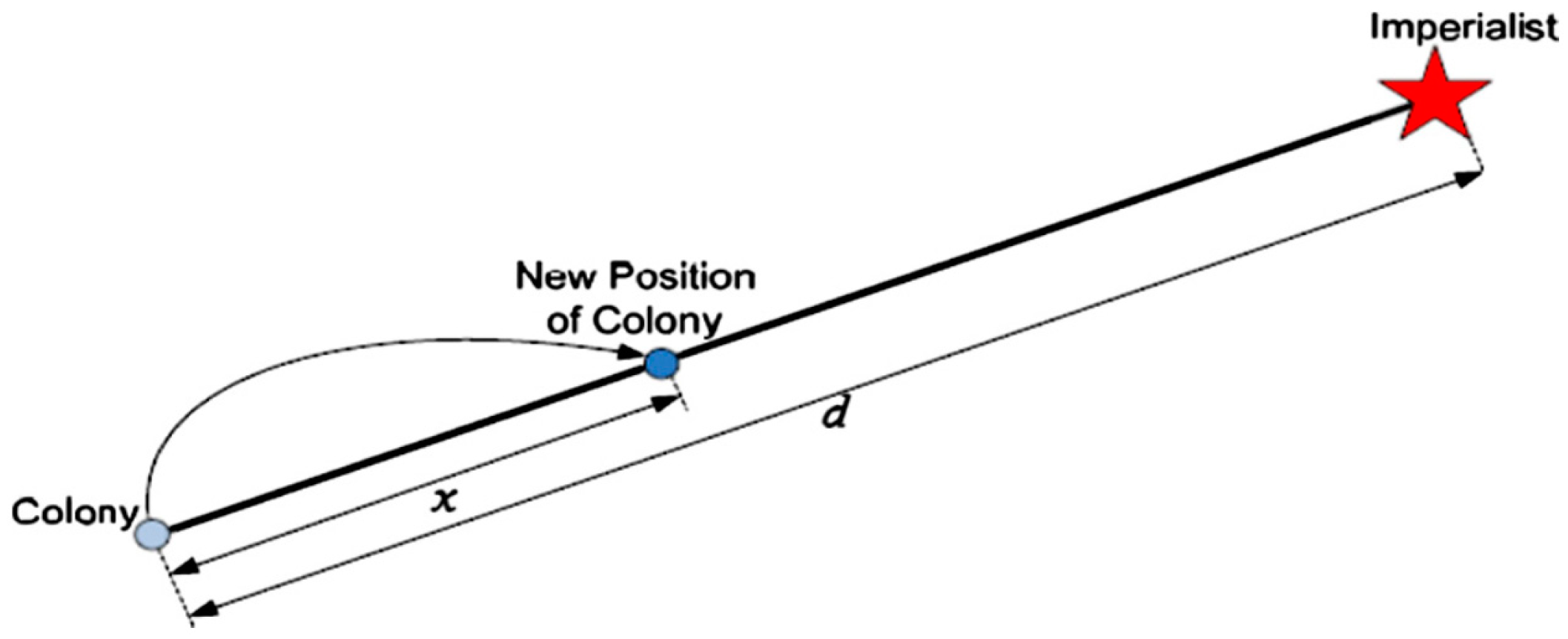
ICA is a novel algorithm based on human political and socialist evolution. The initial population contains N countries among which the countries with the minimum cost are selected as the imperialists and with considering the empire power other countries belong to empires. Applying the attraction policy, the imperialists attract the colonies towards themselves. Figure 4 shows the attraction policy that forms the essential concept of ICA. The imperialists attract these colonies towards themselves respect to their power that described in Equation (18). The total power of each empire is determined by the power of its both parts, the imperialist power plus percent of its average colonies power:
where is the total cost of the n-th empire and n is a positive number (here 0.05).
With the attraction policy, the colony moves towards the imperialist by x unit. Figure 4 shows that the direction of movement is the vector from colony to imperialist, where d is the distance between the colony and imperialist and x is a random variable with uniform distribution. Figure 5 shows the displacement of colony and imperialist [33,34].
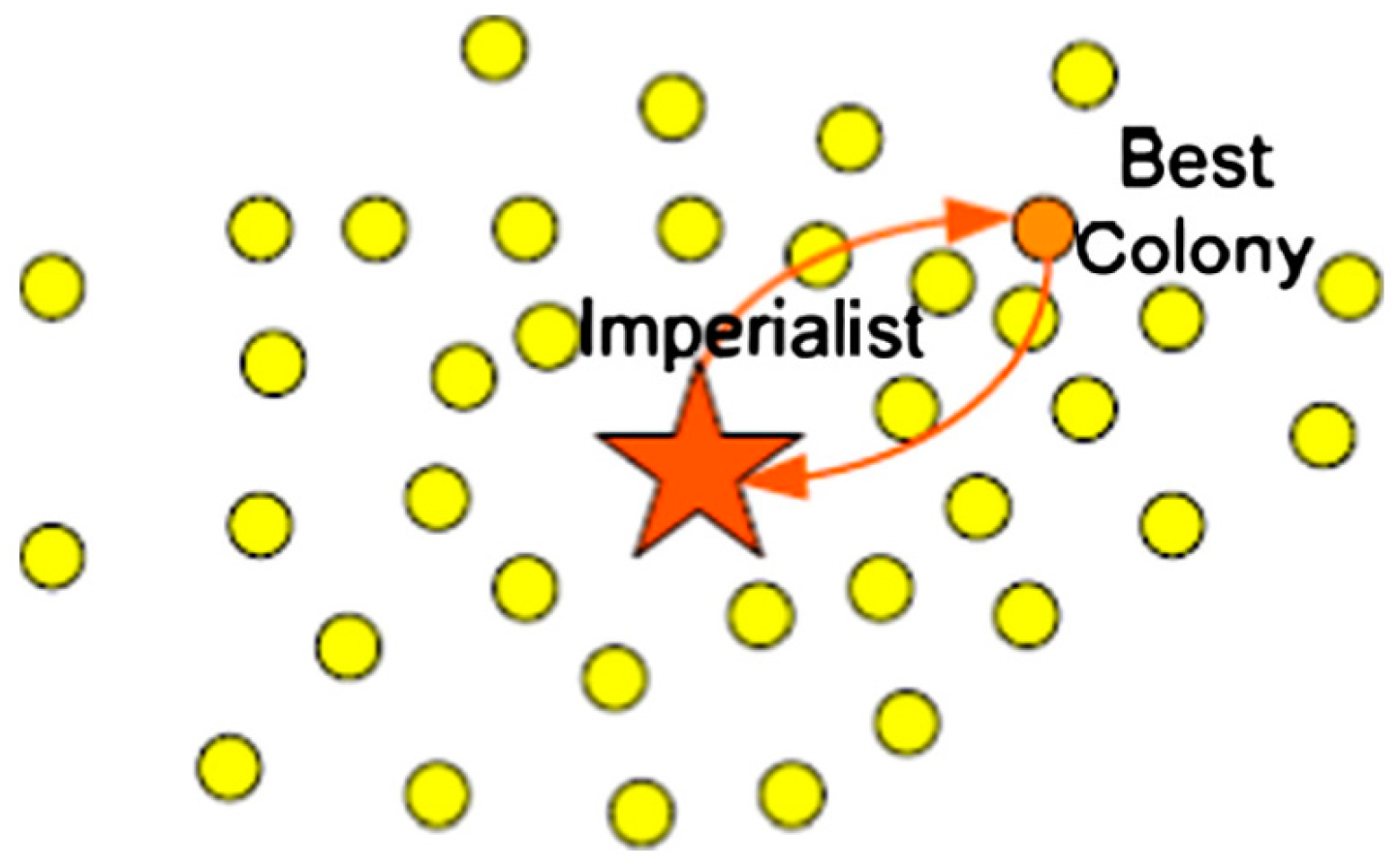
The powerless empires will lose their power and their colonies during the imperialistic competition. Finally, all the empires except the strongest one will collapse and all the colonies will be controlled by this unique empire. Figure 6 shows the ICA flowchart.
Also, this algorithm can be explained in the following stages:
- Stage 1:
- Generation of an initial population for every empire.
- Stage 2:
- Assimilation (select the colonies moving toward their respective imperialist) and Revolution (select the colonies moving toward others that have lower cost).
- Stage 3:
- Comparison between imperialist and the best colony, if the best colony costs are better, their positions are displaced.
- Stage 4:
- Calculate the objective function for every empire.
- Stage 5:
- Choice of the weakest colony and its placement in the best empire.
- Stage 6:
- Collapse of the weak empires.
- Stage 7:
- When only one empire remains, algorithm will stop. Otherwise, return to Stage 2. The last imperialist that remains is the answer.
3.4. Proposed ICA-GA Algorithm
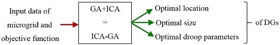
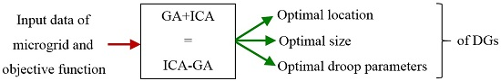
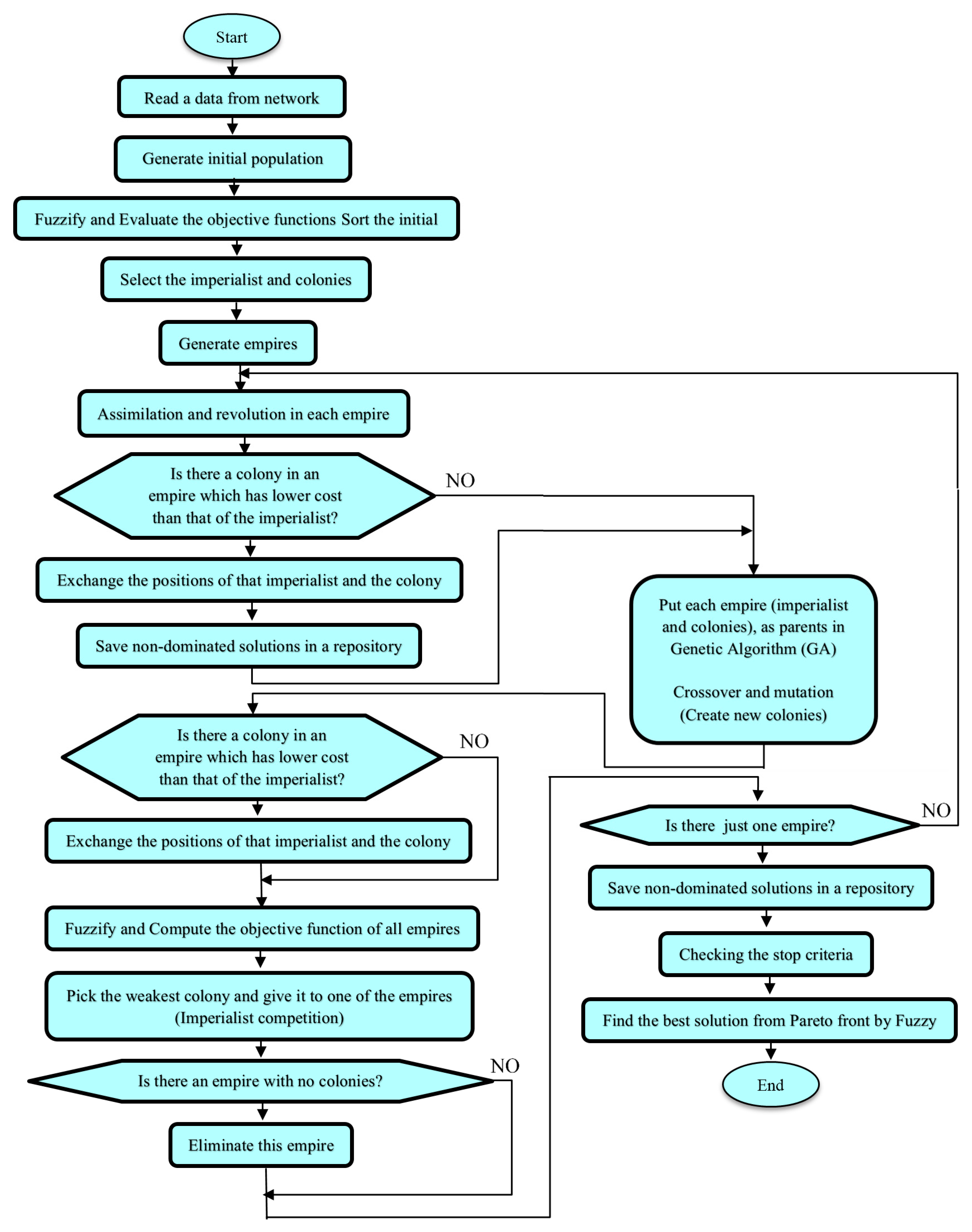
The proposed ICA-GA algorithm is employed for finding the optimal droop parameters, place and production of DGs at the same time. In this scheme, the ICA algorithm is run and employed for finding the optimal droop parameters, place and production of DGs by computing the cost of colonies and imperialist in each empire firstly. Secondly, the GA algorithm is used for generating a new set of colonies in the all search spaces by using operators such as mutation and crossover to obtain a better cost than the imperialist. The proposed ICA-GA algorithm has the benefits of both the ICA and GA methods and better outcomes compared with other common methods in power systems optimization problems. Figure 7 shows the ICA-GA flowchart for finding the optimal droop parameters, place and production of DGs at the same time. Also, this algorithm can be explained in the following stages:
- Stage 1:
- Start.
- Stage 2:
- Read the information regarding grids (such as loads, lines reactance and resistance).
- Stage 3:
- Generate an initial population (such as place and production of DGs and droop parameters).
- Stage 4:
- Fuzzify and evaluate the objective functions.
- Stage 5:
- According to the objective function, arrange the initial population.
- Stage 6:
- Chooe the colonies and imperialists.
- Stage 7:
- Create empires.
- Stage 8:
- Assimilation (select the colonies moving toward their respective imperialist) and Revolution (select the colonies moving toward others that have lower cost).
- Stage 9:
- Compare between imperialist and the best colony; if the best colony costs are better, displace their positions.
- Stage 10:
- Save non-dominated solutions in a repository.
- Stage 11:
- Consider each empire as parents in a GA and generate a new population.
- Stage 12:
- Using the mutation and crossover operators for generating new colonies.
- Stage 13:
- Compared the imperialist and the best colony generated from the GA; if the best colony costs are better, change their positions.
- Stage 14:
- Fuzzify and compue the objective function of all empires.
- Stage 15:
- Imperialist competition (means choosing the weakest colony and put it in the best of the empires).
- Stage 16:
- Collapse the weak empires.
- Stage 17:
- When only one empire remains, the algorithm will stop, otherwise, return to Stage 8. The last imperialist that remains is the answer.
- Stage 18:
- Save the non-dominated solutions in a repository.
- Stage 19:
- Check the stop criteria.
- Stage 20:
- Find the best solution from the Pareto front by the fuzzy normalization Equation (19):
- Stage 21:
- End.
3.5. Proposed Load Flow Algorithm
Traditionally, many algorithms have been used to solve the load flow problem such as Fast-Decoupled and Newton-Raphson. However, these methods may not be useful in distribution networks and MGs because of the divergence of results due to the low value of X/R of MGs. To cope with this divergence problem, a number of algorithms have been proposed [4,6]. Unfortunately, when using such algorithms, we will face two issues, namely the slack bus consideration issue and lack of droop bus consideration issue. Typically, power flow analyses assume one DG as a slack bus to hold the network frequency but this might not be applicable to islanded MGs due to a number of reasons such as low capacities of DGs in MGs, economical reasons and other technical issues. Therefore, we use the droop bus instead of the slack bus and the power flow must be reformulated.
4. Numerical Results and Discussion
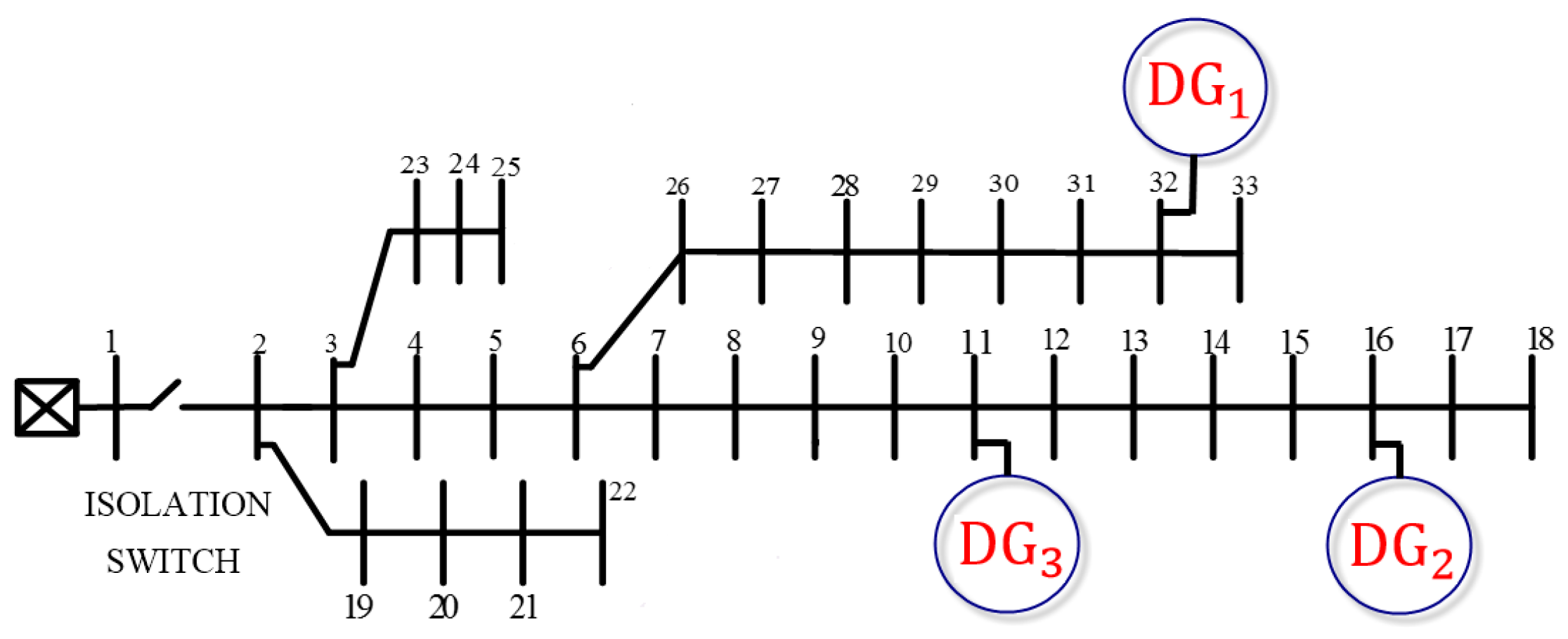
Simulation of the proposed algorithm is done by MATLAB, where an isolated 33 bus IEEE test system with 2.30 Mvar and 3.715 MW total load is considered, as shown in Figure 8 [21]. Two different scenarios are considered and numerical results are presented in this section. In the first scenario, it is supposed that the places of DG units are predetermined and only optimal droop parameters of DG units are obtained. In the second scenario, both optimal production, site and droop parameters of DG units are obtained.
4.1. First Scenario
In this scenario, four DGs were installed at buses 9, 22, 25 and 26. The maximum power of DG units and fuel prices are shown in Table 1. The performance of ICA-GA was compared with ICA, GA and a case with pre-determined (PD) DGs parameters where any optimization process is not conducted. In PD mode, the static droop gains of the DG units are designed in order to share the load demand of the islanded microgrid proportionally with the rated capacity of the DG units [35]; V* and ω* are selected arbitrarily in order to maintain adequate power-quality levels, in terms of maintaining the frequency and voltage within their respective specified operating limits. Such conventional droop settings are capable of providing proper frequency regulation and nearly exact active power sharing among DG units in islanded MGs.
In the optimization procedure, the proposed load flow algorithms were used for each method. Also, for each method the Pareto front solution was obtained and then the fuzzy approach to finding the best solution was used. Figure 9 shows the Pareto front solution provided by ICA-GA.
Table 2 shows the droop control parameters of DGs that achieved by different algorithm and PD case. The acceptable deviation voltage and frequency were considered to be of 5% and 0.5% of the nominal values for PD, respectively. Table 3 gives the values of steady state frequency computed by mentioned algorithms that all the values satisfied the constraints. Active and reactive power of DGs for different methods are shown in Table 4.
Table 5 compares the values of objective functions computed by different methods. Can be seen in this table that the proposed algorithm gives the best values of objective functions and PD provides the worst values.
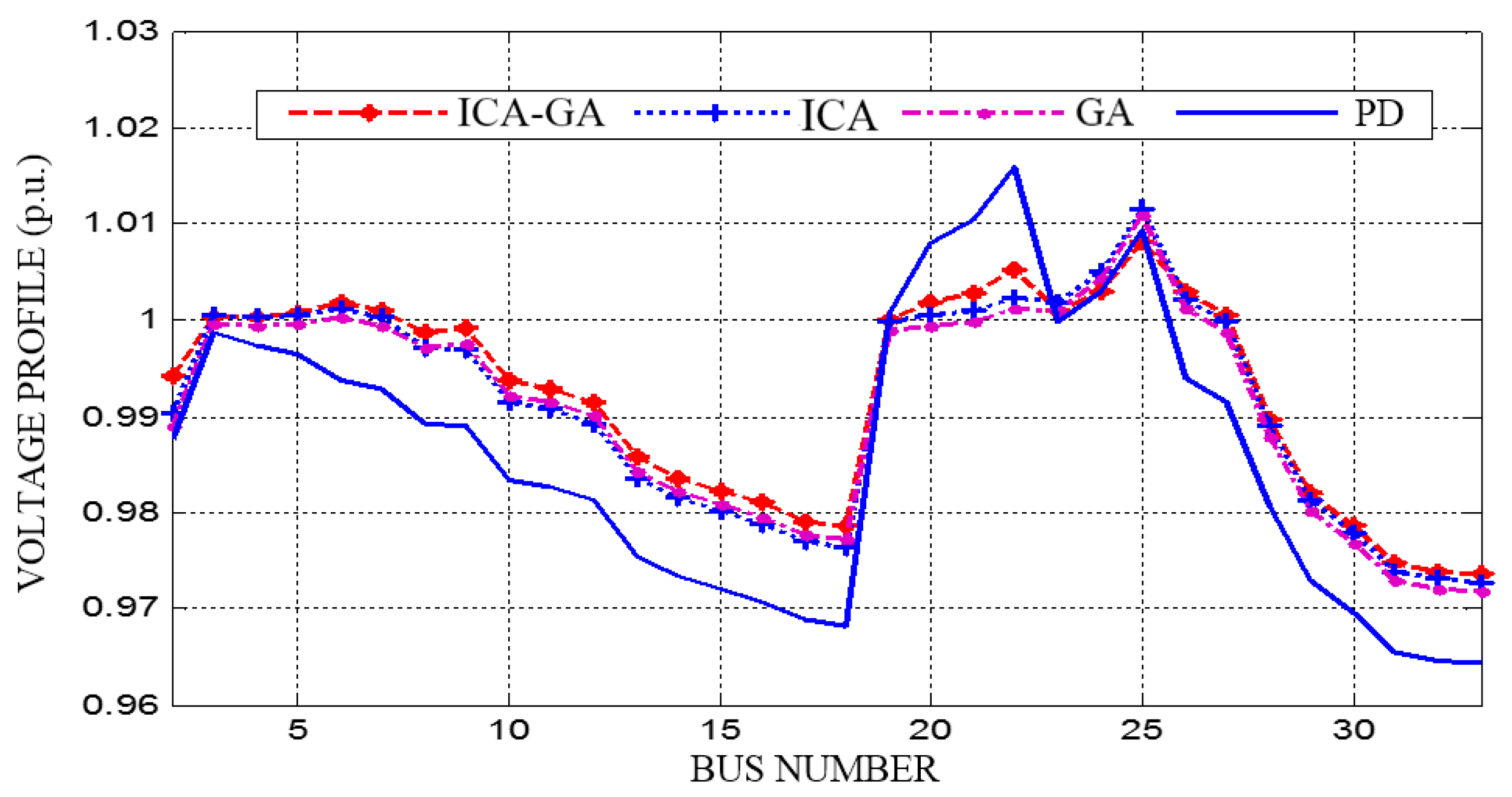
The cost plays an important role in this optimization problem. When just the cost is important the most power are generated by DG1, DG4, DG3 and DG2 respectively. However, the other objective functions such as VV and VSI are of more interested for us, and if the multi-objective function problem optimization is solved, the results of DG unit-generated power are visible in Table 5. Table 6 illustrates the total power and power losses computed by different algorithms. This table shows that proposed method has the lowest active and reactive power losses. Figure 10 depicts the voltage profile of each bus for the different methods. It can be seen that the voltage profile is improved compared to before the optimization at all nodes in each method. The VSI for different methods is shown in Figure 11. In this figure, it is clear that before the optimization of droop parameters, the VSI had been poor for all buses in the MG, while after the optimization this index was improved. Figure 11 also shows that the best VSI is achieved by ICA-GA while the worst is provided by PD.
4.2. Second Scenario
In this scenario, both optimal droop parameters and production-locations of three DGs were identified. Table 7 illustrates the information of DGs and fuel prices.
Table 8 illustrates the droop control parameters of DG units that achieved by different methods in this scenario and PD case. The values of steady state frequency calculated by each method can be seen in Table 9.
Table 10 shows the optimal site and production of DGs and Table 11 shows the objective functions values obtained by ICA-GA, ICA and GA algorithms. The results, mentioned in this table, confirm that all the objective functions include fuel cost, VV and VSI have been amended for all the methods (see Table 5). In total, the simulation results show that the proposed scheme has a superior outcome in comparison with the other algorithms. For example, the fuel cost (), in a yearly basis, obtained by ICA-GA, is the lowest while that of ICA is the highest. Figure 12 shows that optimal location of DG units in 33-bus system with proposed ICA-GA algorithm.
Finally, Table 12 illustrates the total active and reactive power and power losses calculated by each method. This table shows that the ICA-GA algorithm has the lowest active and reactive power losses.
4.3. Assess the Performance of the Proposed Algorithm
To assess the performance of the proposed algorithm a number of optimization problems and their corresponding objective functions and constraints are introduced. Then the proposed algorithm is used for solving such problems. In the considered optimization problems the objective is to find, Min f where f is a benchmark mathematical function, as given in Table 13. Table 14 shows the statistical analysis for comparing different algorithms.
5. Conclusions
This paper puts forth an improvement to the optimization methods concerning the optimal location and operation of DGs in an autonomous MG by increasing the divergence speed and by solving the problem of sticking in local optimal solutions. In addition, the paper gave a solution to both the slack bus consideration and lack of droop bus problems that exist in the conventional load flow literature. It can be concluded that the paper’s approach is an effective tool for practitioners interested in finding both the optimal location and operation of an autonomous MG at the same time.
Author Contributions
Hamed Moazami Goodarzi is the main author of this work. This paper further elaborates on some of the results from his Ph.D. dissertation. Mohammad Hosein Kazemi supervised the research in terms of both scientific and technical expertise.
Conflicts of Interest
The authors declare no conflict of interest.
Nomenclature
| t | Time index. |
| Nobj | Number of objective functions. |
| Ki | The decision maker preference for all objective functions. |
| Phase angle of voltage at bus i. | |
| Ii, | Current and rated current of line i. |
| Maximum apparent power of DGi. | |
| Maximum active power of DGi. | |
| Maximum reactive power of DGi. | |
| Pj | Injected active power to bus j. |
| Qj | Injected reactive power to bus j. |
| Cm(PDGi) | Fuel consumption of DGi. |
| Total active and reactive power at bus i + 1. | |
| Ndr | Number of DGs with droop control. |
| Voltage magnitude of DGi at no load. | |
| Angular frequency of DGi at no load. | |
| Sp, Sq | Active and reactive power static droop gain. |
| The ijth element of admittance matrix. | |
| Phase angle. | |
| Vmin, Vmax | Minim and maximum bus voltage. |
| NB | Number of buses. |
| Pi, Qi | Demand active and reactive power of bus i. |
| Ri, Xi | Resistance and reactance of line i. |
| Pgi, Qgi | Active and reactive power delivered to bus i. |
References
- Olivares, D.E.; Mehrizi-Sani, A.; Etemadi, A.H.; Canizares, C.A.; Iravani, R. Trends in Microgrid Control. IEEE Trans. Smart Grid 2014, 54, 1905–1919. [Google Scholar] [CrossRef]
- Marzband, M.; Alavi, H.; Ghazimirsaeid, S.S.; Uppal, H.; Fernando, T. Optimal energy management system based on stochastic approach for a home Microgrid with integrated responsive load demand and energy storage. Sustain. Cities Soc. 2017, 28, 256–264. [Google Scholar] [CrossRef]
- Fetanat, A.; Khorsaninejad, E. Size optimization for hybrid photovoltaic–wind energy system usingant colony optimization for continuous domains based integerprogramming. Appl. Soft Comput. 2015, 31, 196–209. [Google Scholar] [CrossRef]
- Nekooei, K.; Farsangi, M.M.; Nezamabai, H.; Lee, K.Y. An Improved Multi-Objective Harmony Search for Optimal Placement of DGs in Distribution Systems. IEEE Trans. Smart Grid 2013, 41, 557–567. [Google Scholar] [CrossRef]
- Theo, W.L.; Lim, J.S.; Ho, W.S.; Hashim, H.; Lee, C.T. Review of distributed generation (DG) system planning and optimisation techniques: Comparison of numerical and mathematical modelling methods. Renew. Sustain. Energy Rev. 2017, 67, 531–573. [Google Scholar] [CrossRef]
- Abdi, S.H.; Afshar, K. Application of IPSO-Monte Carlo for optimal distributed generation allocation and sizing. Int. J. Electr. Power Energy Syst. 2013, 44, 786–797. [Google Scholar] [CrossRef]
- Peng, X.; Lin, K.; Zheng, W.; Liu, Y. Crisscross Optimization Algorithm and Monte Carlo Simulation for Solving Optimal Distributed Generation Allocation Problem. Energies 2015, 8, 13641–13659. [Google Scholar] [CrossRef]
- Mahesh, K.; Nallagownden, P.; Elamvazuthi, I. Advanced Pareto Front Non-Dominated Sorting Multi-Objective Particle Swarm Optimization for Optimal Placement and Sizing of Distributed Generation. Energies 2016, 9, 982. [Google Scholar] [CrossRef]
- Huang, C.L.; Huang, W.L.; Chang, H.Y.; Yeh, Y.C.; Tsai, C.Y. Hybridization strategies for continuous ant colony optimization and particle swarm optimizationapplied to data clustering. Appl. Soft Comput. 2013, 13, 3864–3872. [Google Scholar] [CrossRef]
- Zoka, Y.; Sugimoto, A.; Yorino, N.; Kawahara, K.; Kubokawa, J. An economic evaluation for an autonomous independent network of distributed energy resources. Electr. Power Syst. Res. 2007, 77, 831–838. [Google Scholar] [CrossRef]
- Vasiljevska, J.; Pec, J.A.; Lopes, A.; Matos, M.A. Evaluating the impacts of the multi-microgrid concept using multi criteria decision aid. Electr. Power Syst. Res. 2012, 91, 44–51. [Google Scholar] [CrossRef]
- Basu, A.K.; Bhattacharya, A.; Chowdhury, S.; Chowdhury, S.P. Planned Scheduling for Economic Power Sharing in a CHP-Based Micro-Grid. IEEE Trans. Power Syst. 2012, 27, 30–38. [Google Scholar] [CrossRef]
- Zheng, M.; Meinrenken, C.J.; Lackner, K.S. Agent-based model for electricity consumption and storage to evaluate economic viability of tariff arbitrage for residential sector demand response. Appl. Energy 2014, 126, 297–306. [Google Scholar] [CrossRef]
- Moradi, M.H.; Abedini, M.; Hosseinian, S.M.H. Optimal operation of autonomous microgrid using HS–GA. Electr. Power Energy Syst. 2016, 77, 210–220. [Google Scholar] [CrossRef]
- Khorramdel, B.; Raoofat, M. Optimal stochastic reactive power scheduling in a microgrid considering voltage droop scheme of DGs and uncertainty of wind farms. Energy 2012, 45, 994–1006. [Google Scholar] [CrossRef]
- Dilettoso, E.; Rizzo, S.A.; Salerno, N. SALHE-EA: A New Evolutionary Algorithm for Multi-Objective Optimization of Electromagnetic Devices. Intell. Comput. Tech. Appl. Electromagn. 2008, 119, 37–45. [Google Scholar]
- Pipattanasomporn, M.; Willingham, M.; Rahman, S. A mixed-integer linear programming approach for optimal type, size and allocation of distributed generation in radial distribution systems. Electr. Power Syst. Res. 2013, 97, 133–143. [Google Scholar]
- Oyarzabal, J.; Jimeno, J.; RuelaEngler, J.; Hardt, C. Agent based micro grid management system. Int. Conf. Future Power Syst. 2005. [Google Scholar] [CrossRef]
- Dong, F.U.; He, Y.; Chen, X. Optimal control in microgrid using multi-agent reinforcement learning. ISA Trans. 2012, 51, 743–751. [Google Scholar]
- Moradi, M.H.; Eskandari, M.; Hosseinian, S.M.H. Operational Strategy Optimization in an Optimal Sized Smart Microgrid. IEEE Trans. Smart Grid 2015, 6, 1087–1095. [Google Scholar] [CrossRef]
- Moradi, M.H.; Abedini, M.; Hosseinian, S.M.H. A Combination of Evolutionary Algorithm and Game Theory for Optimal Location and Operation of DG from DG Owner Standpoints. IEEE Trans. Smart Grid 2016, 7, 608–616. [Google Scholar] [CrossRef]
- Costa, V.; Oliveira, M.; Guedes, M. Developments in the analysis of unbalanced three-phase power flow solutions. Int. J. Electr. Power Energy Syst. 2007, 29, 175–182. [Google Scholar] [CrossRef]
- Abdel-Akher, M.; Nor, K.; Rashid, A. Improved three-phase power-flow methods using sequence components. IEEE Trans. Power Syst. 2005, 20, 1389–1397. [Google Scholar] [CrossRef]
- Teng, J. A modified Gauss-Seidel algorithm of three-phase power flow analysis in distribution networks. Int. J. Electr. Power Energy Syst. 2001, 24, 97–102. [Google Scholar] [CrossRef]
- Vieira, J.; Freitas, W.; Morelato, A. Phase-decoupled method for three-phase power-flow analysis of unbalanced distribution systems. IEE Proc. Gener. Transm. Distrib. 2004, 151, 568–574. [Google Scholar] [CrossRef]
- Kersting, W.H.; Mendive, D.L. An application of ladder network theory to the solution of three-phase radial power flow problems. In Proceedings of the IEEE PES Winter Meeting & Tesla Symposium, New York, NY, USA, 25–30 January 1975. [Google Scholar]
- Abdelaziz, A.; Farag, H.E.; El-Saadany, E.F.; Mohamed, Y. A novel and generalized three-phase power flow algorithm for islanded microgrids using a Newton trust region method. IEEE Trans. Power Syst. 2013, 28, 190–201. [Google Scholar] [CrossRef]
- Elrayyah, A.; Yilmaz, S. A novel load-flow analysis for stable and optimized microgrid operation. IEEE Trans. Power Deliv. 2014, 26, 899–909. [Google Scholar] [CrossRef]
- Abedini, M. A novel algorithm for load flow analysis in island microgrids using an improved evolutionary algorithm. Int. Trans. Electr. Energy Syst. 2016, 26, 2727–2743. [Google Scholar] [CrossRef]
- Esmaeli, A.; Abedini, M.; Moradi, M.H. A novel power flow analysis in an islanded renewable microgrid. Renew. Energy 2016, 96, 914–927. [Google Scholar] [CrossRef]
- Di Fazio, A.R.; Russo, M.; Valeri, S.; De Santis, M. Sensitivity-Based Model of Low Voltage Distribution Systems with Distributed Energy Resources. Energies 2016, 9, 801. [Google Scholar] [CrossRef]
- Charkravor, M.; Das, D. Voltage stability analysis of radial distribution networks. Int. J. Electr. Power Energy Syst. 2001, 23, 129–135. [Google Scholar] [CrossRef]
- Atashpaz-Gargari, E.; Lucas, C. Imperialist competitive algorithm: An algorithm for optimization inspired by imperialistic competition. IEEE Congr. Evol. Comput. 2007. [Google Scholar] [CrossRef]
- Nazari-Shirkouhi, S.; Eivazy, H.; Ghodsi, R.; Rezaie, K.; Atashpaz-Gargaric, E. Solving the integrated product mix-outsourcing problem by a novel meta-heuristic algorithm: Imperialist competitive algorithm. Expert Syst. Appl. 2010, 37, 7615–7626. [Google Scholar] [CrossRef]
- Pogaku, N.; Prodanovic, M.; Green, T.C. Modeling, analysis and testing of autonomous operation of an inverter-based microgrid. IEEE Trans. Power Electron. 2007, 22, 613–625. [Google Scholar] [CrossRef]
Figure 1.
A sample of MG line.

Figure 2.
Objective membership function.
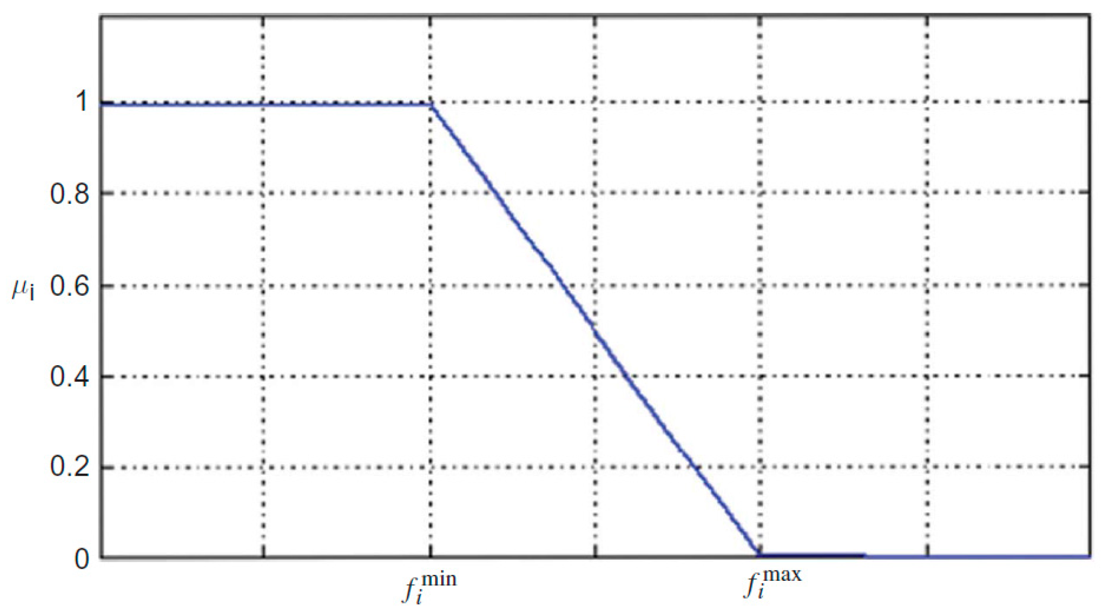
Figure 3.
Flowchart of a GA algorithm for finding optimal site, production and droop parameters of DG.
Figure 3.
Flowchart of a GA algorithm for finding optimal site, production and droop parameters of DG.

Figure 4.
The colony moves using an attraction policy.

Figure 5.
The colony and imperialist displacement.

Figure 6.
Flowchart of the ICA algorithm.
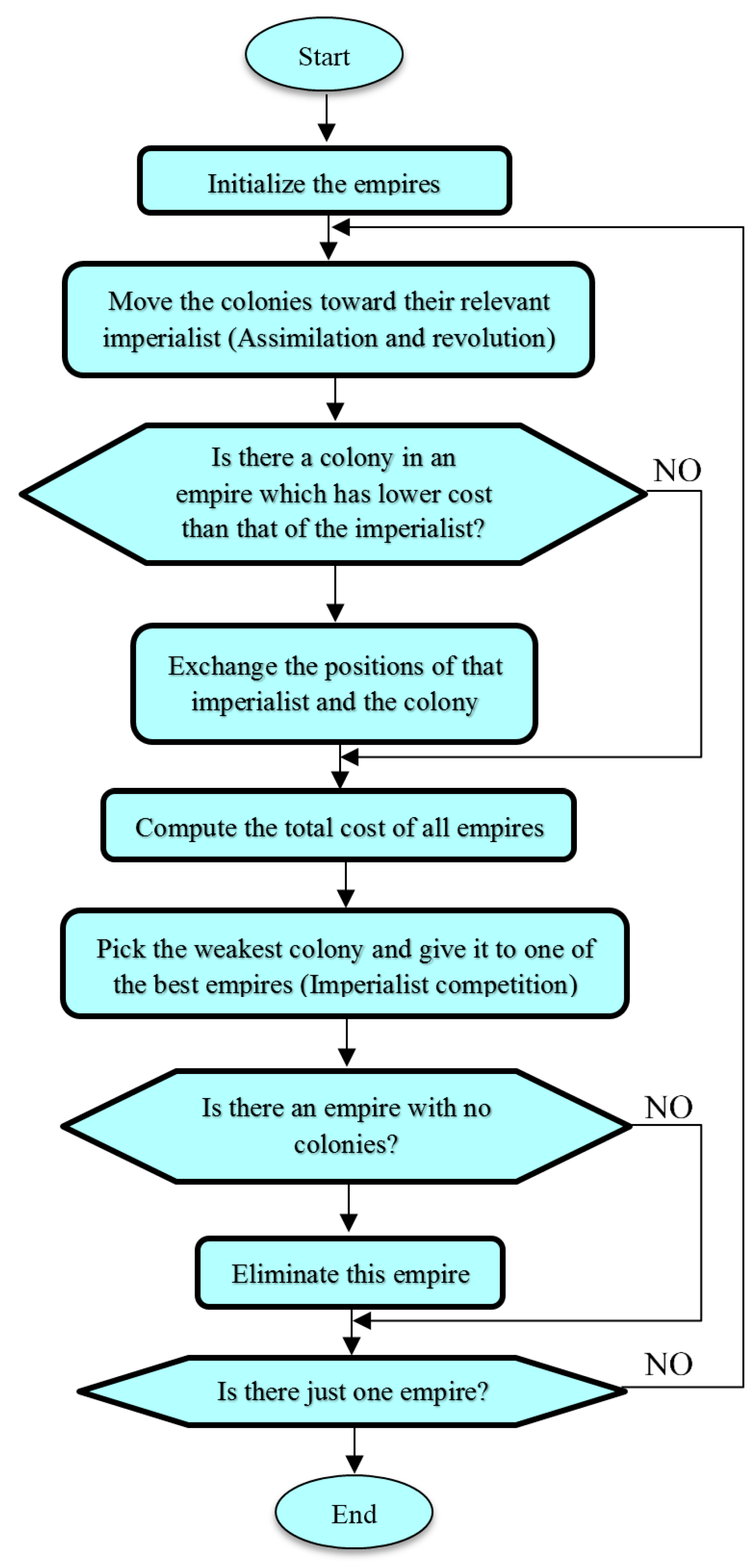
Figure 7.
The ICA-GA algorithm for finding optimal droop parameters, place and production of DGs at the same time.
Figure 7.
The ICA-GA algorithm for finding optimal droop parameters, place and production of DGs at the same time.

Figure 8.
A 33 bus islanded MG test system.
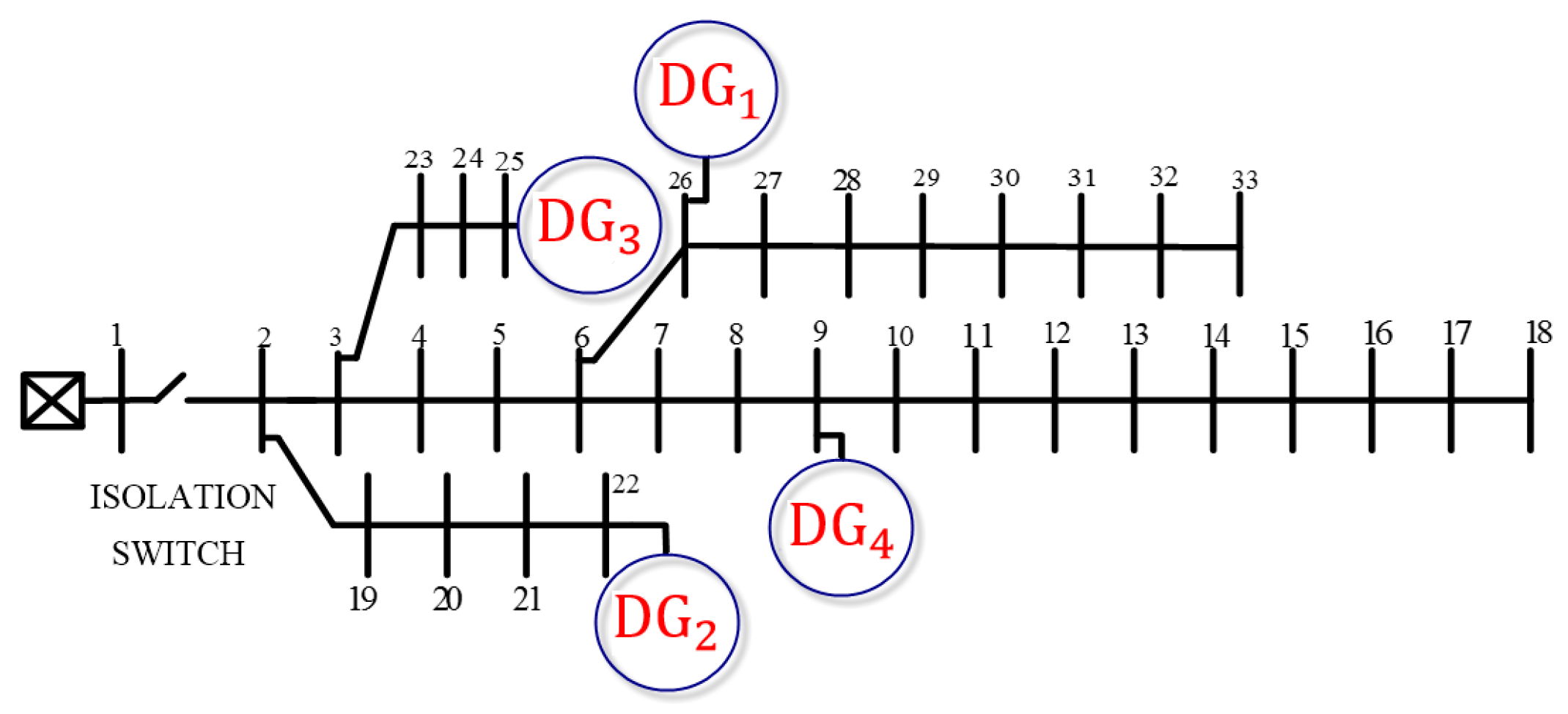
Figure 9.
Pareto front solution of ICA-GA (p.u.).
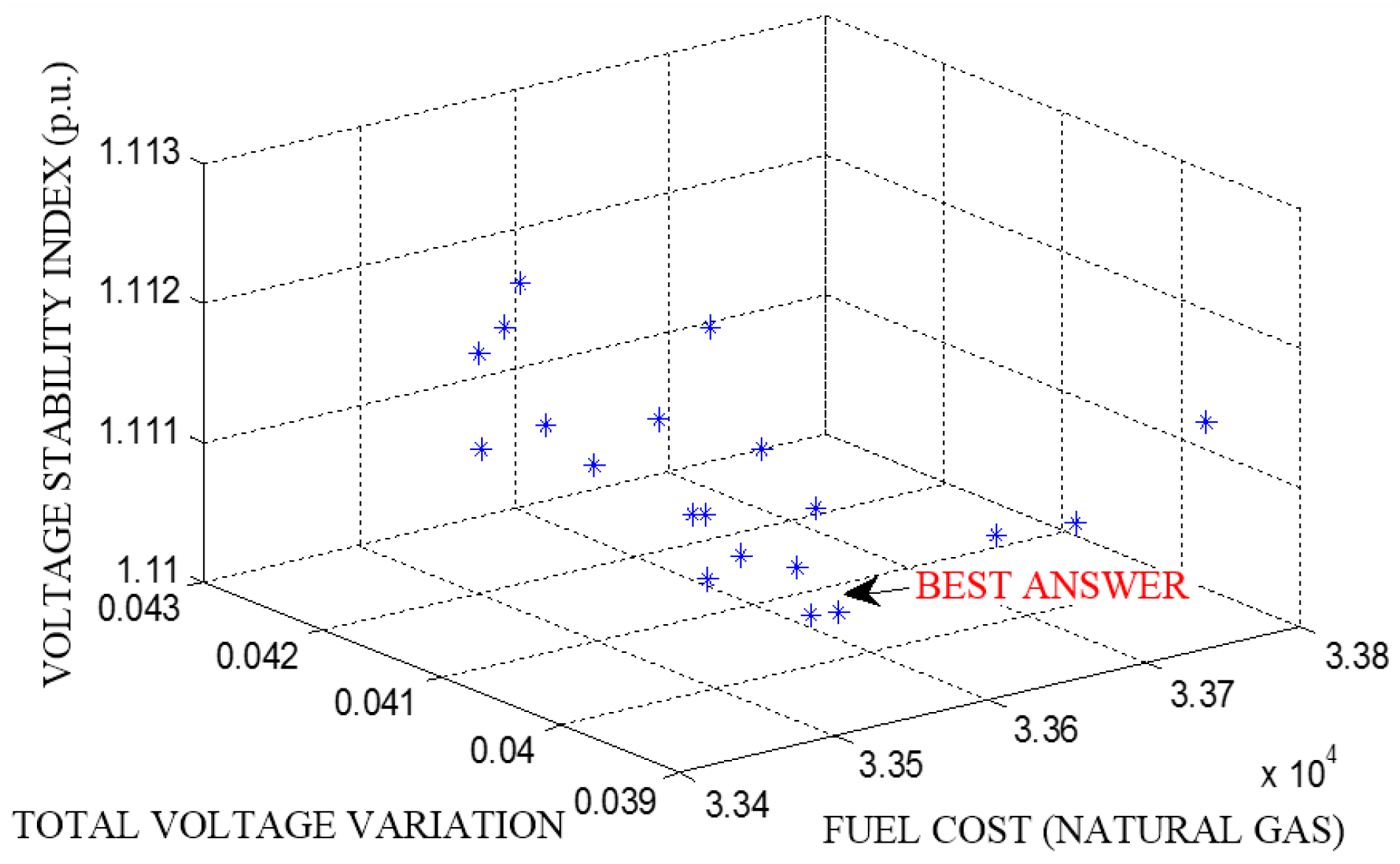
Figure 10.
Voltage profile of MG buses for different methods.

Figure 11.
VSI of MG buses for different methods.
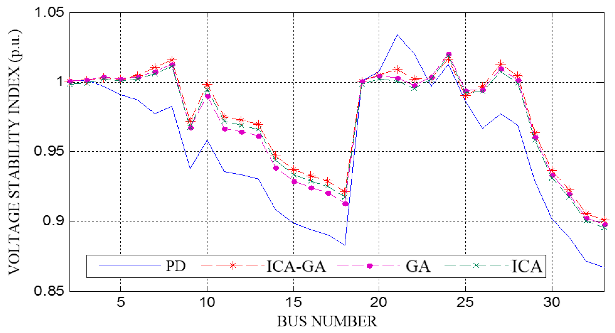
Figure 12.
Optimal location of DG units in 33-bus system with proposed ICA-GA algorithm.


Table 1.
Information of DGs in first scenario.
| DGs | Cost ($/kwh) | QMAX (Mvar) | SMAX (MVA) |
|---|---|---|---|
| 1 | 7.705 | 1.20 | 2 |
| 2 | 11.731 | 0.60 | 1 |
| 3 | 10.363 | 0.90 | 1.5 |
| 4 | 8.475 | 0.45 | 0.75 |
Table 2.
Droop control parameters of DGs in first scenario.
| ICA-GA | ||||
| DGs | Sp | Sq | V* | ω* |
| 1 | 8.9620 × 10⁻⁴ | 9.4745 × 10⁻⁴ | 1.00399 | 1.00014 |
| 2 | 1.7539 × 10⁻³ | 6.1654 × 10⁻³ | 1.00730 | 0.99924 |
| 3 | 2.7767 × 10⁻⁴ | 2.7767 × 10⁻⁴ | 1.00719 | 0.99889 |
| 4 | 8.6905 × 10⁻⁴ | 4.0476 × 10⁻³ | 1.00039 | 0.99920 |
| GA | ||||
| DGs | Sp | Sq | V* | ω* |
| 1 | 1.1429 × 10⁻³ | 8.4977 × 10⁻³ | 1.01099 | 1.00050 |
| 2 | 5.1635 × 10⁻⁴ | 7.4864 × 10⁻³ | 1.00469 | 0.99883 |
| 3 | 2.7082 × 10⁻⁴ | 1.7903 × 10⁻³ | 1.01238 | 0.99900 |
| 4 | 1.2012 × 10⁻³ | 3.4293 × 10⁻³ | 0.99970 | 0.99951 |
| ICA | ||||
| DGs | Sp | Sq | V* | ω* |
| 1 | 1.0616 × 10⁻³ | 2.5128 × 10⁻⁴ | 1.00250 | 1.00028 |
| 2 | 1.3653 × 10⁻³ | 9.9832 × 10⁻³ | 1.00349 | 0.99898 |
| 3 | 4.9624 × 10⁻⁴ | 5.7692 × 10⁻³ | 1.01069 | 0.99911 |
| 4 | 2.7240 × 10⁻³ | 3.2605 × 10⁻³ | 0.99820 | 1.00019 |
| PD | ||||
| DGs | Sp | Sq | V* | ω* |
| 1 | 1.1151 × 10⁻³ | 0.025 | 1.015 | 1.000 |
| 2 | 2.2284 × 10⁻³ | 0.050 | ||
| 3 | 1.4863 × 10⁻³ | 0.0333 | ||
| 4 | 2.9712 × 10⁻³ | 0.0667 | ||
Table 3.
Values of steady state frequency in first scenario.
| Methods | ICA-GA | ICA | GA | PD |
|---|---|---|---|---|
| Steady state frequency | 0.99861 | 0.99853 | 0.99868 | 0.99840 |
Table 4.
Active (PDG (MW)) and reactive (QDG (Mvar)) power of DGs for different methods in first scenario.
Table 4.
Active (PDG (MW)) and reactive (QDG (Mvar)) power of DGs for different methods in first scenario.
| Method | PDG1 | QDG1 | PDG2 | QDG2 | PDG3 | QDG3 | PDG4 | QDG4 |
|---|---|---|---|---|---|---|---|---|
| ICA-GA | 1.7072 | 1.0449 | 0.3592 | 0.3142 | 1.0084 | 0.6531 | 0.6789 | 0.3187 |
| ICA | 1.6484 | 1.0665 | 0.3296 | 0.1196 | 1.1688 | 0.7476 | 0.6094 | 0.3987 |
| GA | 1.5924 | 1.0311 | 0.2905 | 0.2391 | 1.1816 | 0.7708 | 0.6910 | 0.2916 |
| PD | 1.44 | 0.58 | 0.72 | 0.49 | 1.077 | 0.82 | 0.54 | 0.45 |
Table 5.
Objective functions of proposed algorithm and other methods in first scenario.
| Objective Function | ICA-GA | ICA | GA | PD |
|---|---|---|---|---|
| f1 ($/h) | 33,571.48 | 33,844.40 | 33,778.44 | 35,250.32 |
| f2 (p.u.) | 1.1103 | 1.1139 | 1.1141 | 1.1533 |
| f3 (p.u.) | 0.0401 | 0.0455 | 0.0422 | 0.0724 |
Table 6.
Total active and reactive power and power losses in first scenario.
| Method | PDG (MW) | QDG (Mvar) | PLoss (MW) | Qloss (Mvar) |
|---|---|---|---|---|
| ICA-GA | 3.7537 | 2.3309 | 0.0387 | 0.0309 |
| ICA | 3.7562 | 2.3324 | 0.0412 | 0.0324 |
| GA | 3.7555 | 2.3326 | 0.0405 | 0.0326 |
| PD | 3.7678 | 2.3434 | 0.0528 | 0.0436 |
Table 7.
Information of DGs in second scenario.
| DGs | Cost ($/kwh) | QMAX (Mvar) | SMAX (MVA) |
|---|---|---|---|
| 1 | 7.705 | 1.20 | 2 |
| 2 | 8.475 | 1 | 1.4 |
| 3 | 10.363 | 0.90 | 1.5 |
Table 8.
Droop control parameters of DGs in second scenario.
| ICA-GA | ||||
| DGs | Sp | Sq | V* | ω* |
| 1 | 6.6164 × 10⁻⁴ | 8.41723 × 10⁻⁴ | 1.0050 | 0.99957 |
| 2 | 1.4079 × 10⁻³ | 6.32359 × 10⁻⁴ | 1.0024 | 1.00010 |
| 3 | 2.5979 × 10⁻⁴ | 1.57613 × 10⁻³ | 1.0093 | 0.99887 |
| GA | ||||
| DGs | Sp | Sq | V* | ω* |
| 1 | 9.9932 × 10⁻⁴ | 9.05791 × 10⁻³ | 1.0130 | 1.00010 |
| 2 | 1.8415 × 10⁻³ | 5.46881 × 10⁻⁴ | 1.0017 | 1.00039 |
| 3 | 1.1165 × 10⁻⁴ | 9.70592 × 10⁻³ | 1.0097 | 0.99879 |
| ICA | ||||
| DGs | Sp | Sq | V* | ω* |
| 1 | 9.0791 × 10⁻⁴ | 9.13376 × 10⁻³ | 1.0149 | 0.99964 |
| 2 | 1.3044 × 10⁻³ | 9.57501 × 10⁻⁴ | 1.0001 | 0.99988 |
| 3 | 1.1495 × 10⁻⁴ | 4.85376 × 10⁻³ | 1.0055 | 0.99869 |
Table 9.
Values of steady state frequency in second scenario.
| Methods | ICA-GA | ICA | GA |
|---|---|---|---|
| Steady state frequency | 0.99857 | 0.99852 | 0.99864 |
Table 10.
Location and generated power of DGs for different methods in second scenario.
| Method | ICA-GA | ICA | GA | |
|---|---|---|---|---|
| Location | 32 | 11 | 13 | |
| DG1 | P (MW) | 1.5114 | 1.2336 | 1.4610 |
| Q (Mvar) | 1.1070 | 1.1706 | 1.199 | |
| Location | 16 | 29 | 32 | |
| DG2 | P (MW) | 1.0867 | 1.0426 | 0.9503 |
| Q (Mvar) | 0.5749 | 0.9184 | 0.4944 | |
| Location | 11 | 30 | 8 | |
| DG3 | P (MW) | 1.1548 | 1.4789 | 1.3435 |
| Q (Mvar) | 0.6482 | 0.2429 | 0.6387 |
Table 11.
Objective functions of proposed algorithm and other methods in second scenario.
| Objective Function | ICA-GA | ICA | GA |
|---|---|---|---|
| f1 ($/h) | 32,822.31 | 33,666.8 | 33,233.5 |
| f2 (p.u.) | 1.0519 | 1.0804 | 1.0537 |
| f3 (p.u.) | 0.0305 | 0.0335 | 0.0407 |
Table 12.
Total active and reactive power and power losses in second scenario.
| Method | PDG (MW) | QDG (Mvar) | PLoss (MW) | Qloss (Mvar) |
|---|---|---|---|---|
| ICA-GA | 3.7529 | 2.3301 | 0.0379 | 0.0301 |
| ICA | 3.7551 | 2.3319 | 0.0401 | 0.0319 |
| GA | 3.7548 | 2.3321 | 0.0398 | 0.0321 |
Table 13.
Benchmark functions.
| Name | Functions |
|---|---|
| Michalewicz | , where n = 5; m = 10; and 0 ≤ ≤ |
| Schaffer | , where n = 2; and −100 100 |
| Shubert | , where n = 2; and −10 ≤ ≤ 10 |
| Sphere | , where n = 30; and −100 ≤ ≤ 100 |
| Griewank | , where n = 30; and −600 ≤ ≤ 600 |
| Ackley | , where n = 30; and−32 ≤ ≤ 32 |
Table 14.
Statistical analysis for comparing different algorithms.
| Test Function | Global Min | PSO | HTS | ICA-GA |
|---|---|---|---|---|
| Michalewicz | −4.687658 | −4.6877 | −4.6876 | −4.68759 |
| Schaffer | 0 | 0 | 0.04367 | 0 |
| Shubert | −186.7309 | −186.7309 | −186.719 | −186.7309 |
| Sphere | 0 | 1.04173 × 10⁻²⁵ | 7.87894 × 10⁻⁵ | 2.8349 × 10−218 |
| Griewank | 0 | 1.217 × 10⁻¹³ | 0.9184 | 0 |
| Ackley | 0 | 1.6462 | 0.15998 | 8.88178 × 10⁻¹⁶ |
© 2017 by the authors. Licensee MDPI, Basel, Switzerland. This article is an open access article distributed under the terms and conditions of the Creative Commons Attribution (CC BY) license (http://creativecommons.org/licenses/by/4.0/).
Share and Cite
MDPI and ACS Style
Moazami Goodarzi, H.; Kazemi, M.H. A Novel Optimal Control Method for Islanded Microgrids Based on Droop Control Using the ICA-GA Algorithm. Energies 2017, 10, 485. https://doi.org/10.3390/en10040485
AMA Style
Moazami Goodarzi H, Kazemi MH. A Novel Optimal Control Method for Islanded Microgrids Based on Droop Control Using the ICA-GA Algorithm. Energies. 2017; 10(4):485. https://doi.org/10.3390/en10040485
Chicago/Turabian StyleMoazami Goodarzi, Hamed, and Mohammad Hosein Kazemi. 2017. "A Novel Optimal Control Method for Islanded Microgrids Based on Droop Control Using the ICA-GA Algorithm" Energies 10, no. 4: 485. https://doi.org/10.3390/en10040485
Note that from the first issue of 2016, this journal uses article numbers instead of page numbers. See further details here.