
A Multiple Data Fusion Approach to Wheel Slip Control for Decentralized Electric Vehicles


1
School of Mechanical Engineering, Nanjing University of Science and Technology, Nanjing 210094, China
2
Department of Greenergy, National University of Tainan, No. 33, Section 2, Shu-Lin Street, Tainan 700, Taiwan
*
Author to whom correspondence should be addressed.
Energies 2017, 10(4), 461; https://doi.org/10.3390/en10040461
Submission received: 29 January 2017
/
Revised: 24 March 2017
/
Accepted: 27 March 2017
/
Published: 2 April 2017
(This article belongs to the Special Issue Advances in Electric Vehicles and Plug-in Hybrid Vehicles 2017)
Abstract
:Currently, active safety control methods for cars, i.e., the antilock braking system (ABS), the traction control system (TCS), and electronic stability control (ESC), govern the wheel slip control based on the wheel slip ratio, which relies on the information from non-driven wheels. However, these methods are not applicable in the cases without non-driven wheels, e.g., a four-wheel decentralized electric vehicle. Therefore, this paper proposes a new wheel slip control approach based on a novel data fusion method to ensure good traction performance in any driving condition. Firstly, with the proposed data fusion algorithm, the acceleration estimator makes use of the data measured by the sensor installed near the vehicle center of mass (CM) to calculate the reference acceleration of each wheel center. Then, the wheel slip is constrained by controlling the acceleration deviation between the actual wheel and the reference wheel center. By comparison with non-control and model following control (MFC) cases in double lane change tests, the simulation results demonstrate that the proposed control method has significant anti-slip effectiveness and stabilizing control performance.
1. Introduction
Recently, electric and hybrid vehicles have become more and more popular because of their internal electric motors. The electric motor can provide propulsion and regenerative braking in a unified mechanism [1,2]. Consequently, the transportation efficiency is better than conventional gasoline engine cars. Due to the merits of independent control for each motor, active safety control systems have made significant innovated decentralized electric vehicles in recent years [3,4,5,6,7]. The power decentralized electric vehicle employs the independent drive motors to propel the vehicle system. This freedom makes wheel slip control a crucial issue. Wheel slip control is a key foundation to the vehicle active safety control system, especially for electronic stability control (ESC), because compared with the antilock braking system (ABS) and traction control system (TCS), the ESC needs wheel slip control to generate longitudinal tire force, as well as lateral tire force.
The intrinsic explanation of wheel slip is that the output torque of the actuator exceeds the maximum friction force between the tire and the road surface [8,9,10,11]. However, the friction force cannot be measured directly, and there are changes with regards to the road surface and vehicle states. In order to solve this problem faced in vehicle dynamic control, the implementations available for wheel slip control fall into two classes: indirect torque control methods based on wheel slip ratio and direct torque control ones based on the vehicle or wheel model. According to the curve, the former methods maintain the optimal wheel slip ratio in a stable adhesion region to obtain the maximum friction force. To calculate the wheel slip ratio, the wheel speed is easily detected by a sensor installed on the rotational wheel axle, and the speed of non-driven wheels replace chassis speed for physical and economic reasons. Clearly, this replacement is not applicable in the cases without non-driven wheels for 4-Wheel Drive (4WD) systems. No matter how ingenious the chassis speed acquisition is, the result of this indirect method is inherently inaccurate. Although some dedicated sensors can measure the chassis speed directly [12], they are too sensitive to the environment and too expensive for commercial applications. Therefore, some researchers focus on designing the estimators without the chassis speed [13,14]. However, these methods are difficult for practical use, and their control robustness is still challenging against the significant variation in tire-road conditions because they only consider typical road conditions.
On the other hand, distinguished from indirect methods based on wheel slip ratio, direct methods based on the model of vehicle or wheel do not need information on the chassis speed. The model following control (MFC) method only makes use of the wheel speed and the motor torque to determine the maximum feedback gain for anti-slip control [15,16,17]. Fewer control inputs with a simple control structure facilitate the practicability, low cost, and higher reliability of this method. However, considering the worst stability situation, such a method impairs the control performance to determine the compensation gain. Additionally, the tuned algorithms and parameters are specific for established vehicles or wheel models such that the MFC cannot adapt to the variation in vehicle mass or equivalent vehicle mass transfer. Vehicle wheel slip caused by tire traction deterioration can be compensated by many approaches, such as sliding model control, robust control, fuzzy control, and adaptive control [18,19,20,21,22]. The maximum transmissible torque estimation (MTTE) method requires neither the chassis speed nor the tire-road information and takes advantage of a relaxation factor (i.e., the ratio of the vehicle acceleration to wheel acceleration) to estimate the maximum transmissible torque as the limitation of the motor torque [6,23,24]. The MTTE, irrespective of the vehicle mass and road conditions, can restrain the wheel slip effectively. Nevertheless, the increased motor cost charged by excessively precise torque output limits the practical use of this method.
Consequently, different from the methods above, this paper proposes a novel wheel slip control method by eliminating the acceleration deviation between the actual wheel and the reference wheel center to suppress the wheel slip trend at the initial stage. The rest of this paper is organized as follows. Section 2 introduces the proposed wheel slip control system, including a one-wheel vehicle model, dynamic analysis, and detailed controller design. Section 3 gives the evaluation setups. The simulation results and discussions are offered in Section 4. Finally, Section 5 gives some concluding remarks.
2. Proposed Approach
This section discusses the methodologies implemented in the study. Note that the proposed approach is designed for power decentralized electric vehicles. Additionally, the vehicle system is assumed to adhere to rigid body dynamics.
2.1. One-Wheel Vehicle Model
In this subsection, the dynamics analysis of vehicle longitudinal motion is discussed based on the one-wheel vehicle model, which can be described as in Figure 1. Table 1 lists the parameter definitions. The dynamics equations for the calculation of the longitudinal vehicle motions are described as follows:
Note that the “propulsion torque” and “braking torque” are amalgamated as “driving torque ”.
2.2. Dynamic Analysis for Anti-Slip
Substituting Equation (5) into Equation (4), the friction force, , can be expressed as:
Assuming that the driving torque is constant, then, it can be found that the higher the wheel circumferential acceleration , the lower the friction force that can be obtained.
Generally, the friction force is less than the maximum value that the road surface can provide and increases as the drive torque goes up. Based on the tire–friction relations, before the maximum traction force is achieved, the friction force is proportional to the slip ratio. After that, when the slip ratio continues to increase given lateral or longitudinal force, both of them will deteriorate quickly due to the saturation of the traction force.
Substituting in Equation (1) into Equation (4), the driving torque, including two movements, i.e., the body longitudinal motion and wheel rotation, can be expressed as:
Here, the driving resistance , which is related to the chassis speed and vehicle shape, is assumed to be zero. Hence:
In some conditions where the vehicle runs at high speeds and thus require higher anti-slip performance, should be estimated in real time.
The regular operation of steering a vehicle can typically be treated as a linear motion [25], excluding the situation of the vehicle always performing turning control. Consequently, it is easy to see if no slip is expected, i.e., ; the vehicle acceleration in linear motion then can be obtained as . Therefore, in a pure rolling condition where no slip occurs, the wheel acceleration equals that of the chassis in Equation (8). When slip stars to occur, i.e., part of the output torque cannot be transmitted to the chassis by the tire-road interaction, the driving torque containing two parts, can be rewritten as:
where
Here, represents the desired maximum torque to maintain a pure rolling state. stands for extra torque that exists when the slip ratio is not equal to zero. It is invalid torque that does not contribute to the propulsion. It turns into rotational kinetic energy when the wheel self-spins in skidding scenarios. Note that less of the wasted energy may be stored in different areas, such as potential energy in the suspension. However, most of the wasted energy is directly delivered to the wheels. Consequently, the proposed control method, which makes use of the deviation between the accelerations of the wheel and the chassis directly, adjusts the output driving torque to constrain the wheel slip by:
This formula indicates that the calculation of the desired drive torque for anti-slip control requires only the wheel and chassis accelerations. represents the torque distribution command from the upper yaw-moment control, which the driver demands.
2.3. Data Fusion for Reference Acceleration
According to classical rigid body dynamics, it is inaccurate for Equation (8) to take the chassis acceleration as the reference for four independent wheels. Thus, in order to ensure the accuracy of the proposed control method, the reference accelerations of each wheel center, which are rigid on the vehicle body, are utilized to replace the chassis acceleration.
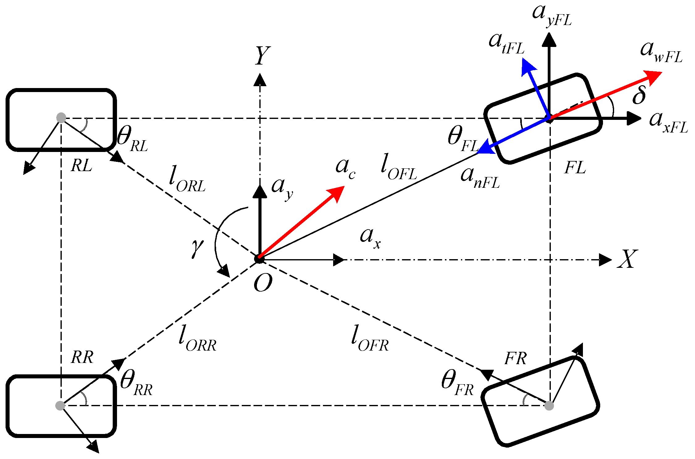
The reference accelerations are derived from measurable quantities including the chassis longitudinal acceleration, the chassis lateral acceleration, and the yaw rate. In this paper, an inertia sensor is installed at the vehicle center of mass, simultaneously measuring these physical quantities. Taking the front left wheel as an example, as shown in Figure 2, is the vehicle’s center of mass (CM); , , and the longitudinal acceleration, lateral acceleration, and yaw rate of the chassis, respectively. Let be , , , or , i.e., four wheels; represents the wheel acceleration; the steer angle of front two wheels; the horizontal distance from the vehicle centroid to the wheel center; the intersection angle between and the vehicle body side; and and the longitudinal and lateral reference acceleration at each wheel center, respectively. As shown in Figure 2, the proposed steering kinematics is assumed under a left turn.
For each wheel, due to the rotation of the vehicle body, the reference wheel center acceleration comprises another two components besides the chassis and . As shown in Figure 2, they are the tangential and normal accelerations, i.e., and , defined as:
By the geometric relations, the reference acceleration and of each wheel center can be calculated as:
Here, for a certain vehicle, the body parameters, e.g., and , are fixed such that the precision of the calculated acceleration only has a relationship with the inertia sensor, which is installed at the vehicle center of mass. Additionally, the data fusion algorithm proposed in this paper ignores the influences of the chassis vertical, pitching, and rolling motions. However, if higher calculation accuracy is required, all related quantities should be taken into account synthetically, which can be actualized by a sensor with six degrees of freedom.
2.4. Proposed Control Scheme
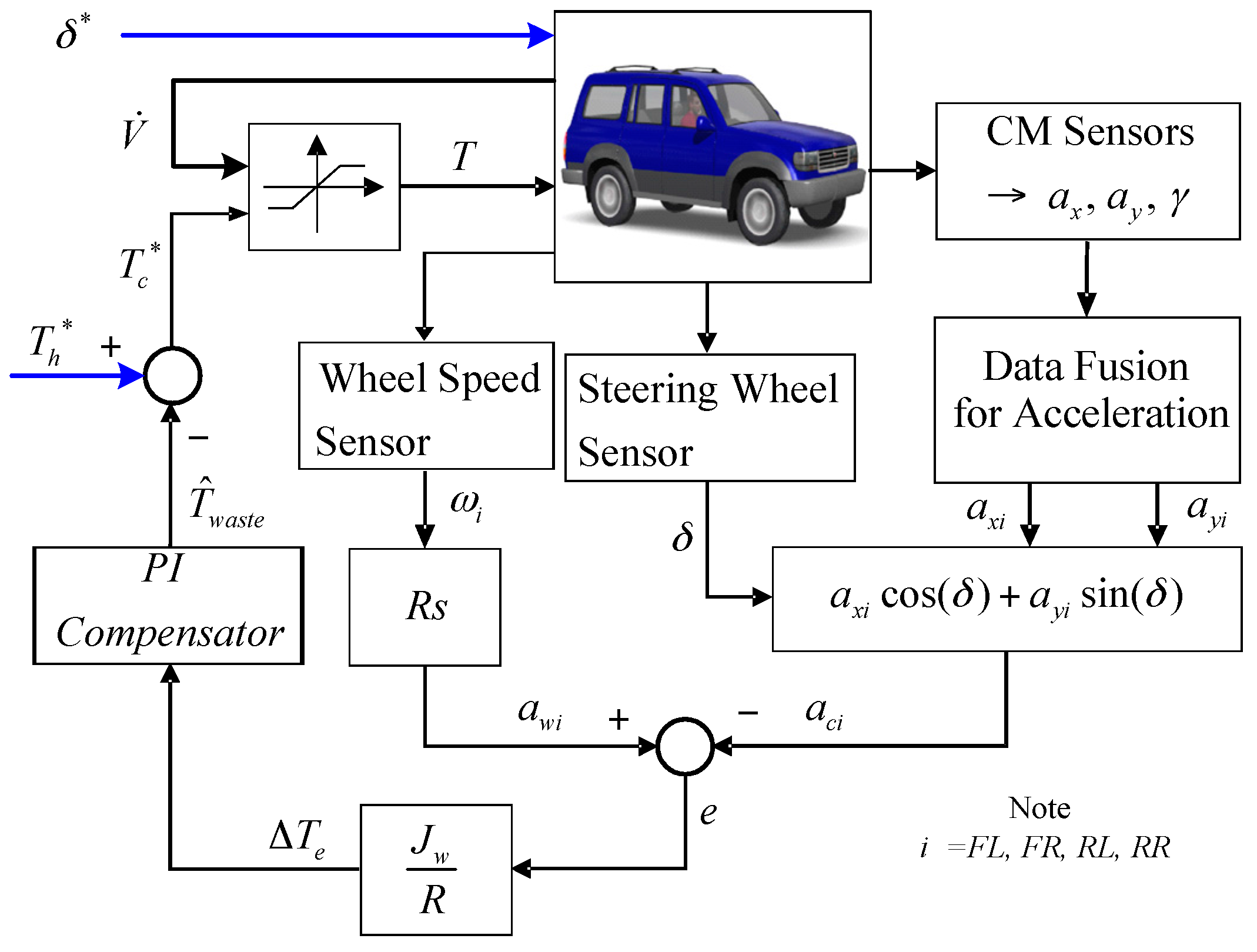
The proposed wheel slip control system is illustrated in Figure 3. Based on the proposed data fusion algorithm for the reference acceleration, the mechanism obtains the longitudinal and lateral components of the reference acceleration. As shown in Figure 2, the resultant reference acceleration has a different direction with the actual wheel acceleration, which indicates the wheel travel direction. Therefore, the reference accelerations of each wheel center should be rewritten according to:
where represents the steer angle of both front wheels, which is measured by an angular sensor. The slight toe-out difference is neglected.
The actual wheel acceleration , achieved by taking the time derivative of the wheel speed , which is measured directly, should be equal or very close to , in the complete adhesion condition. Then, the eventual output torque is constrained by:
in which, and denote the PI compensator gains that ensure the wheel slip being controlled; is the maximum non-slip output torque that the wheel can provide; herein is a reference command that represents the initial input torque requests from the driver. Herein, is the actual steering angle command given from the operator. From Equations (9) and (11), we can have . Under the manipulation of the PI compensator, . Consequently, the propulsion torque leads to .
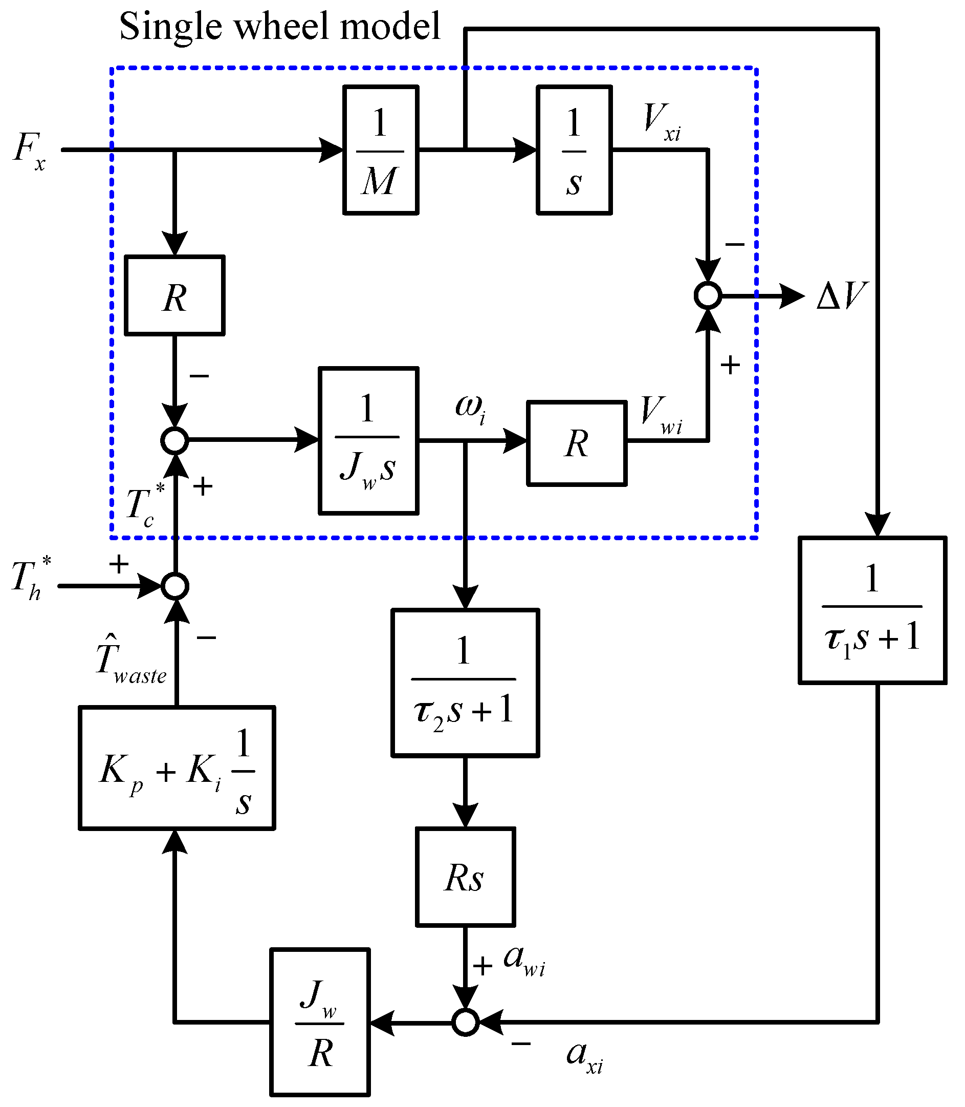
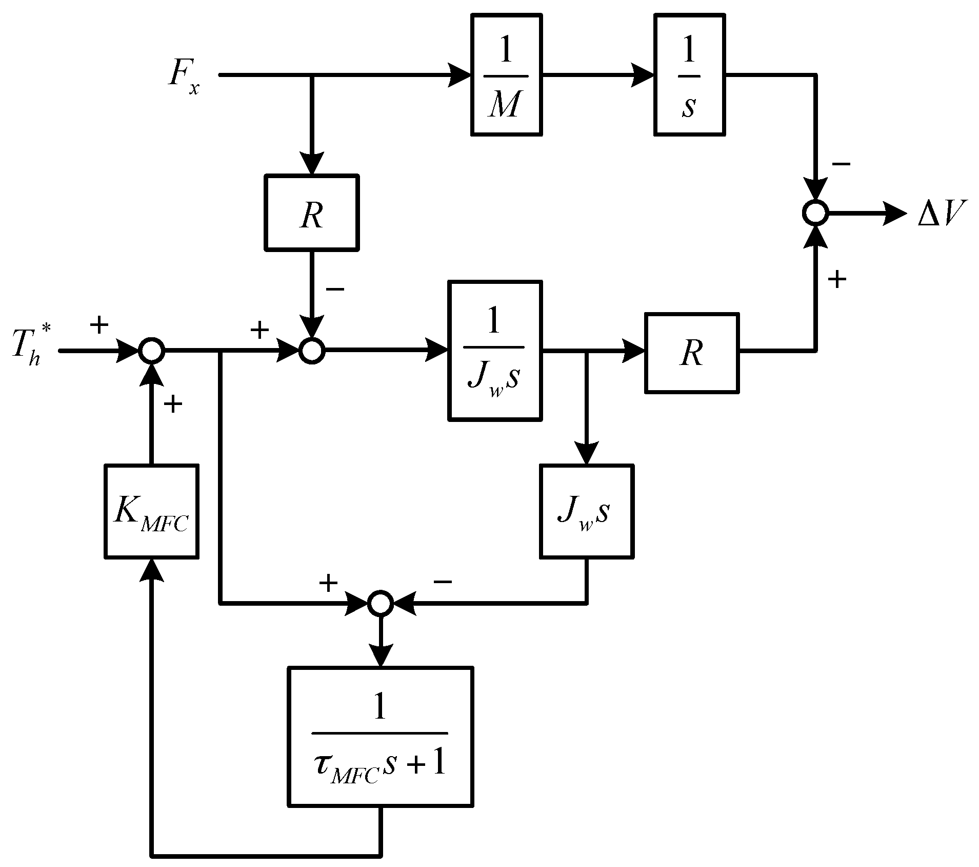
Basically, the proposed wheel slip control is a kind of disturbance estimation. Its stability analysis is the same in each wheel. Based on the control block diagram of Figure 3 and the relevant motion equations, the following Figure 4 illustrates the equivalent model of the proposed control. Note that the driving resistance is assumed to be zero. and are the time constants for low-pass filters. stands for the deterioration of wheel skidding. is the linear velocity of a quarter car. According to Mason’s gain formula, the following transfer functions can be obtained.
Equation (17) represents the transfer function of anti-slip control. According to the following Routh table:
Hence, Equation (17) is stable if:
Clearly, the first column of Routh table reveals that all numbers are positive. Hence, Equation (17) is stable. The second transfer function of Equation (18) shows the characteristic equation that:
Analyzing Equation (21) uncovers that the real part of the roots shall be negative numbers. Equation (18) is also stable in consequence. Since both Equations (17) and (18) are stable, it leads to the conclusion that the proposed wheel slip control system is stable all the time.
3. Evaluation Setups
In order to evaluate the performance of the proposed approach, this study applied software CarSim with Simulink (Version 8.03, Mechanical Simulation Corporation, Ann Arbor, MI, USA, 2012) to carry out the simulation. Table 2 shows the specifications of the test vehicle, which is a type of sport utility vehicle (SUV). In addition, we have set the powertrain of this vehicle in CarSim as “4-wheel drive with all external powertrain components”. Hence, the electric motors are set in Simulink. In our configuration, the testing electric vehicle is fully power decentralized, which can be used in the evaluation of the proposed sensor fusion strategy. Note that, in the simulations, the test vehicle is regarded as a rigid body and the maximum wheel steering angle is 36°. Three types of tests are carried out for the evaluations.
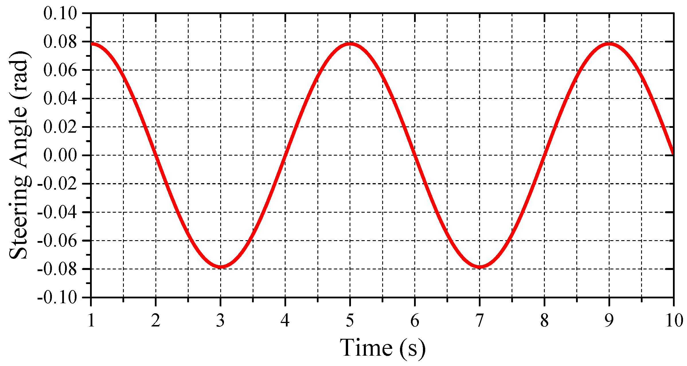
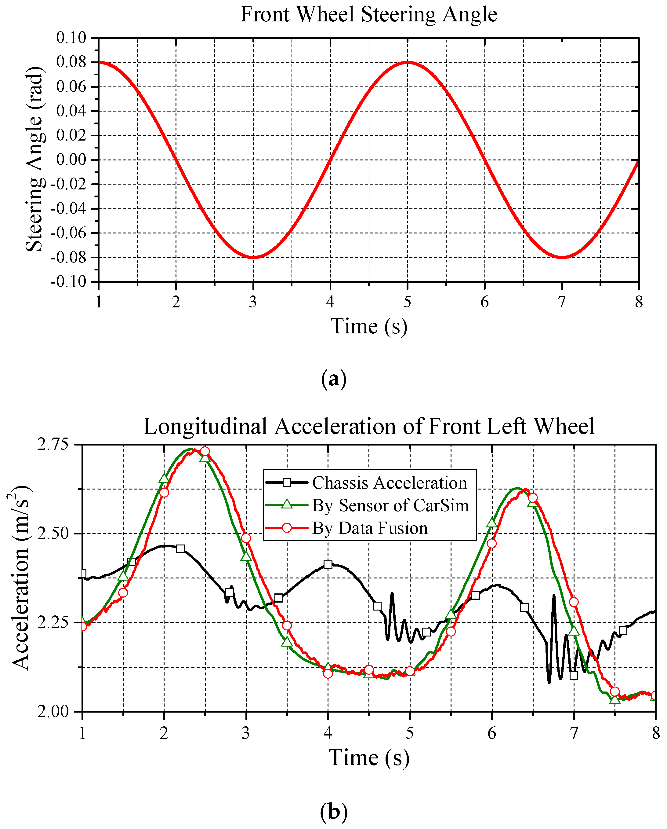
The first test is the verification of the proposed data fusion algorithm. The test conditions are an initial speed of 50 km/h and a road friction coefficient of 0.85. The front wheel steering angle is maneuvered as seen in Figure 5. In order to evaluate the effectiveness of the proposed data fusion algorithm, four acceleration sensors are installed at the center of four wheels in CarSim.
The second test is made under a defined double lane change (DLC). This test maneuver is performed to verify the effectiveness of the proposed wheel slip control. The DLC test is recognized as a benchmark for evaluating steering stability, e.g., the international standard ISO 3888-2 [26]. In order to eliminate the randomness of the driver’s actions, a built-in UMTRI preview driver, which indicates the most average driver in CarSim, is set to make the steering decision for trajectory tracking; the preview time is 0.5 s. All tests are set to the same value for fair comparison. The initial speed for the DLC test is 38 km/h, and two road friction coefficients are set to 0.8 and 0.45. The maximum output torque of each wheel is 500 Nm. Note that the PI compensator gains in Figure 3 are set to and . Note that regardless of the scenario, the PI gains are always set to the same value in the evaluations.
The third test verifies the robustness of lighter and heavier vehicle masses. This test is carried out on the DLC test with the vehicle weights of 1589 kg and 1939 kg, respectively. The results of this test lead to evaluate the robustness of the proposed approach when the vehicle’s mass is changed.
4. Results and Discussion
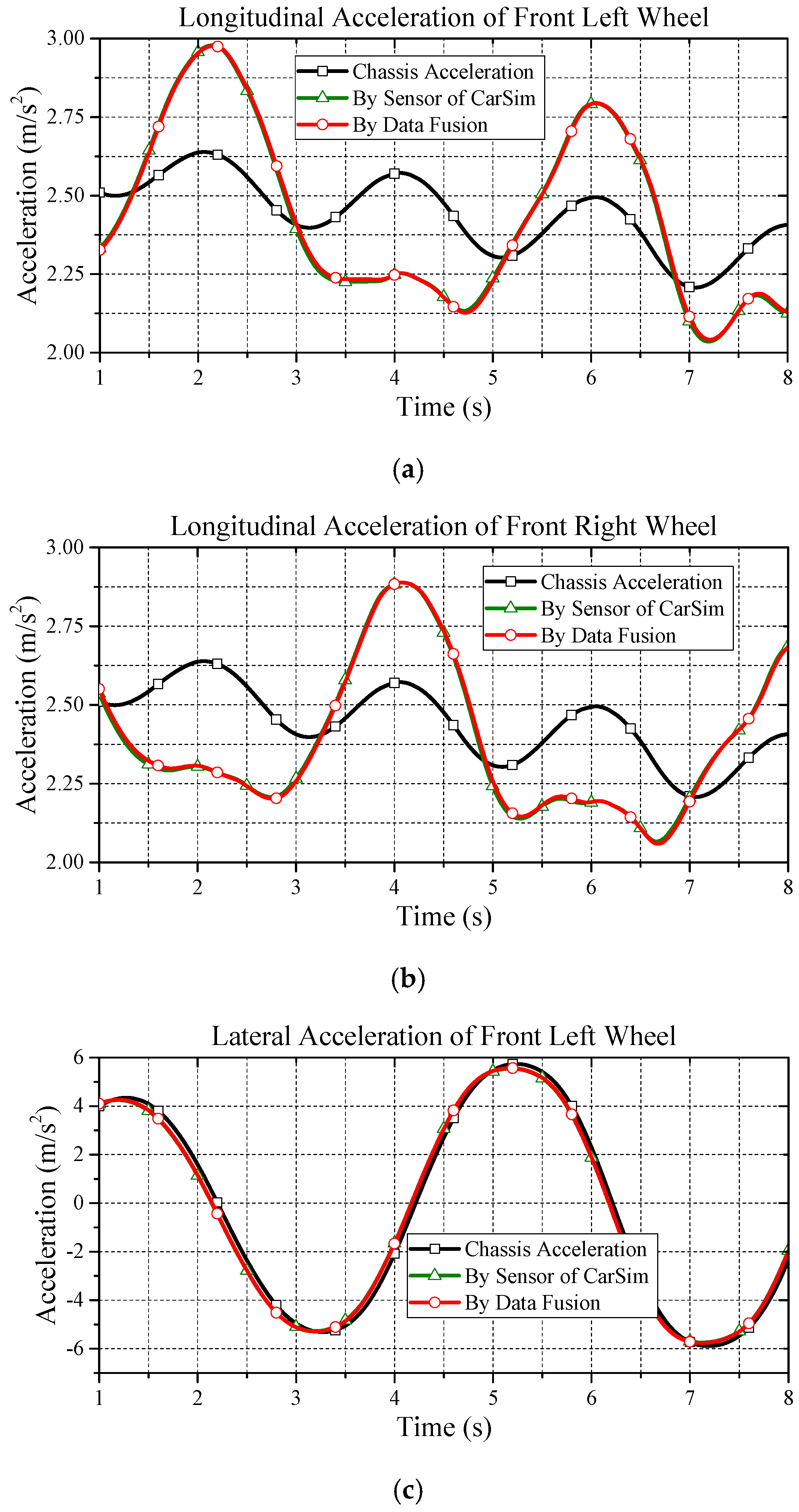
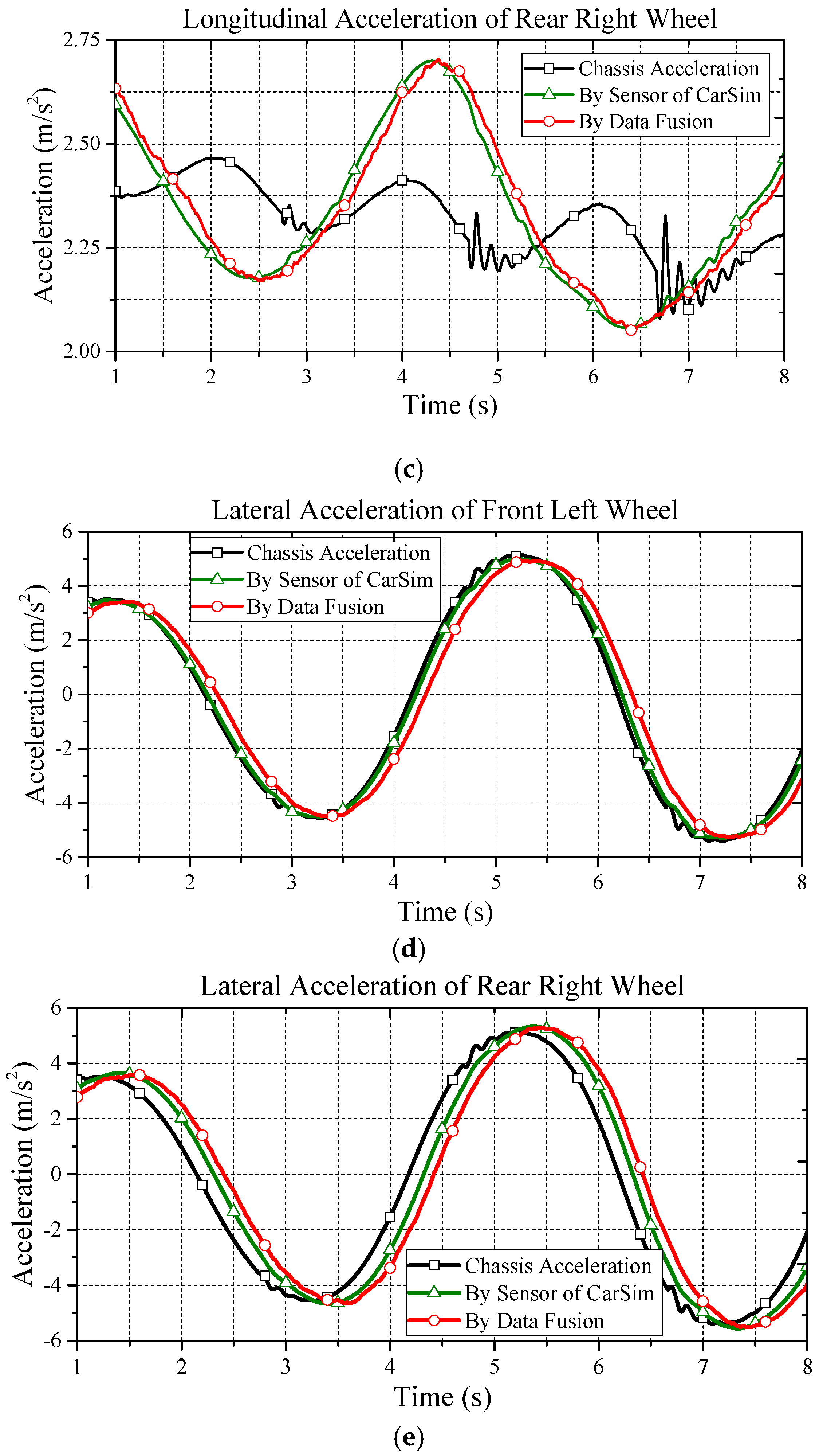
This paper presents a wheel slip control scheme based on the proposed data fusion algorithm. In the following, the aforementioned issues will be verified under the corresponding simulations. In order to verify the wheel slip control, the data fusion performance is firstly evaluated. Note that based on the steering command of Figure 5, Figure 6 shows the simulation results of data fusion as they pertain to the front wheels. Compared to the proposed estimation with the information from sensors, as can be seen in this figure, the proposed approach for acceleration estimation is reliable. Additionally, considering the cost of the chassis acceleration sensor, the proposed approach is a cost-effective solution. Moreover, in this simulation, we can also observe the acceleration discrepancy between the CM and individual wheels. Therefore, without the data fusion from all wheels, using the acceleration information from a single wheel instead of chassis acceleration is not recommended.
In order to evaluate performance of the proposed data fusion under a noisy environment, a mechanism of white noise is added in the feedback states. The noise is added on measured data of each wheel according to the data from a real sensor: TAMAGAWA AU7428N200 (TAMAGAWA SEIKI Co., Ltd., Nagano Prefecture, Japan). The noise for acceleration on the CM is up to 0.049 m/s2. The noise for the yaw rate is up to 1 deg/s. The noise effect for the wheel speed occurs up to 15 rpm. Figure 7 shows the comparative results. As can be seen in this figure, the proposed data fusion algorithm shows acceptable performance against the effect of noise.
According to [8], a rival MFC approach is employed for performance comparison, whose the control block diagram is depicted in Figure 8. In this figure, the should satisfy the following stability condition:
Note that the minimum of is . In this paper, we set . is the time constant of the low-pass filter.
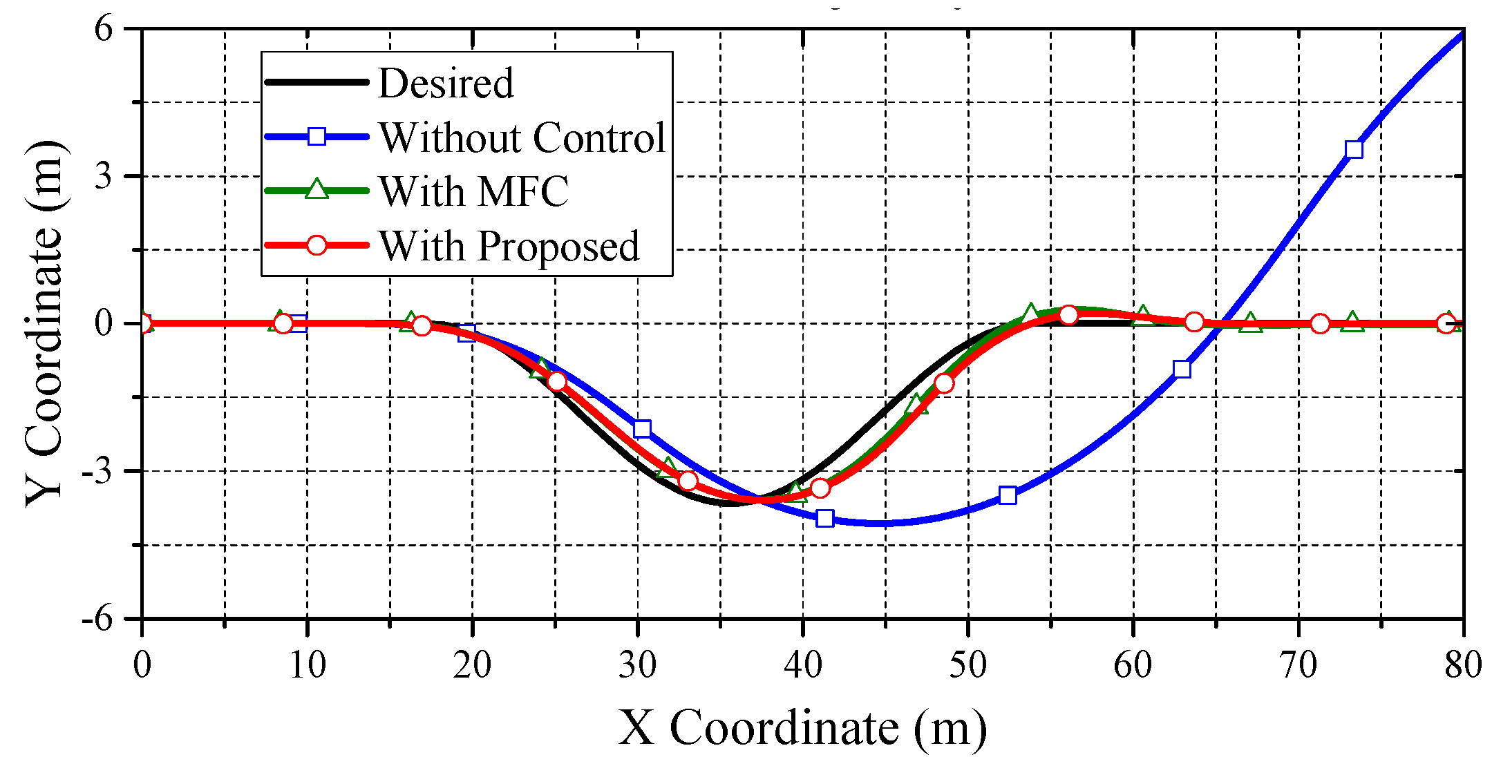
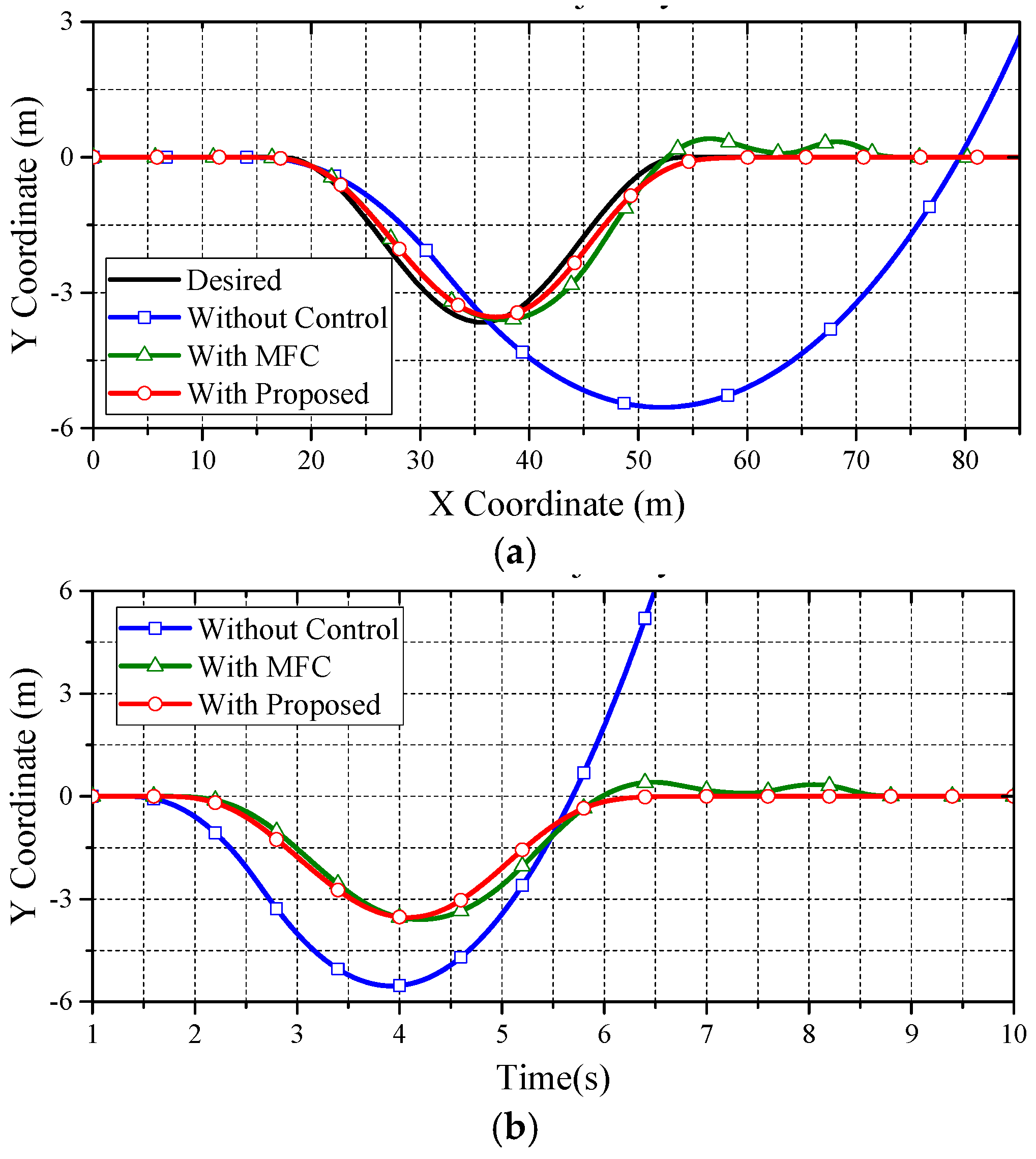
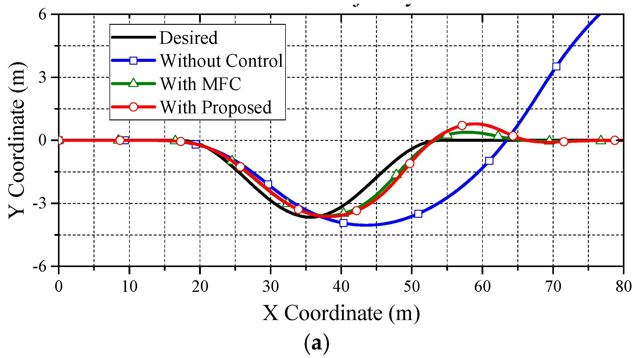
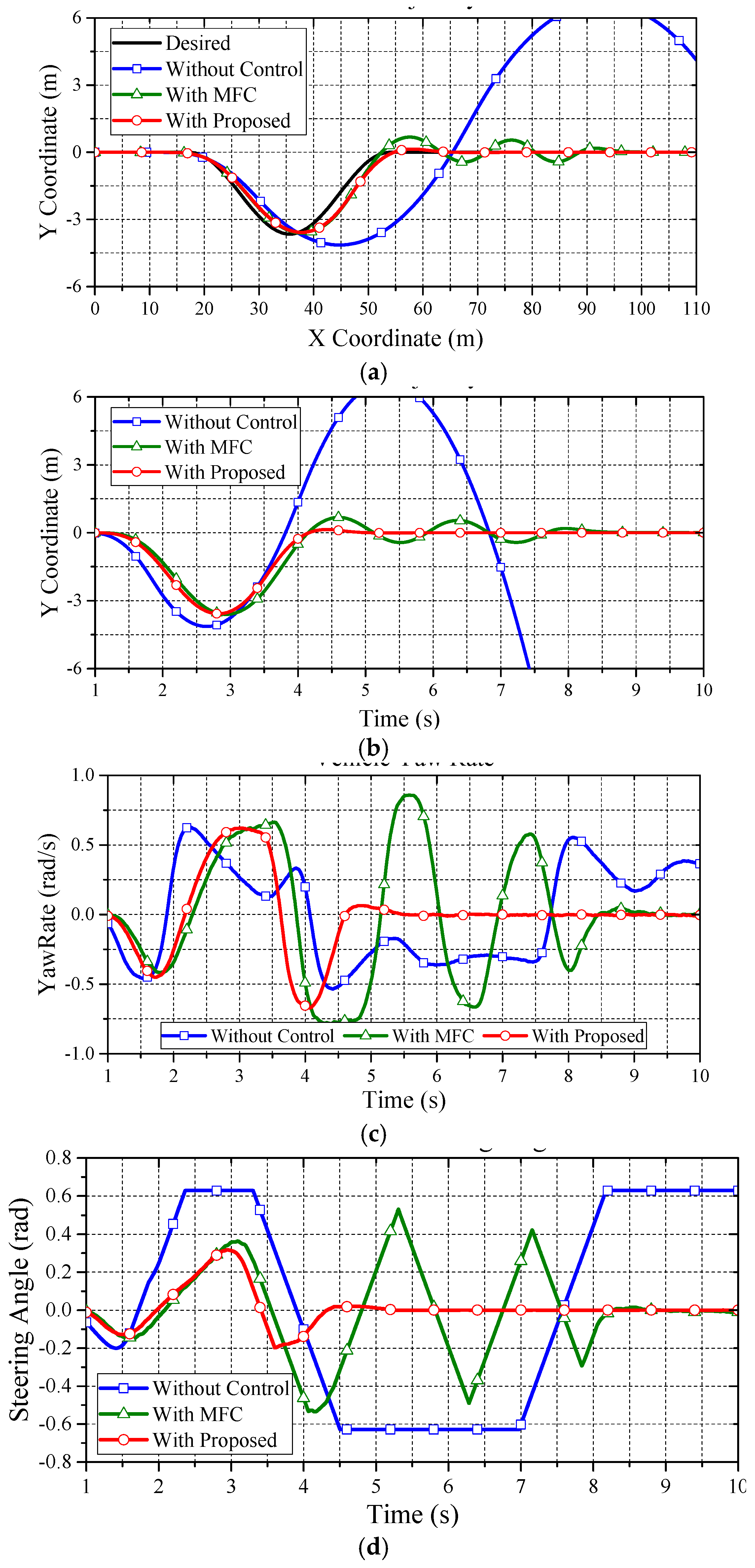
Based on the reliable foundation of proposed data fusion of the acceleration estimation, the performance of the wheel slip control can be evaluated. In order to fairly observe the performance differences from all approaches, the upper control of ESC is turned off in CarSim. In the following, the second test with high and low friction coefficients are evaluated. Figure 9 reveals the main comparisons of the trajectory from the DLC test under the friction coefficient of 0.8. Clearly, the vehicle without control and the vehicle with MFC cannot pass the DLC test, while the vehicle with the proposed control can follow the desired trajectory smoothly.
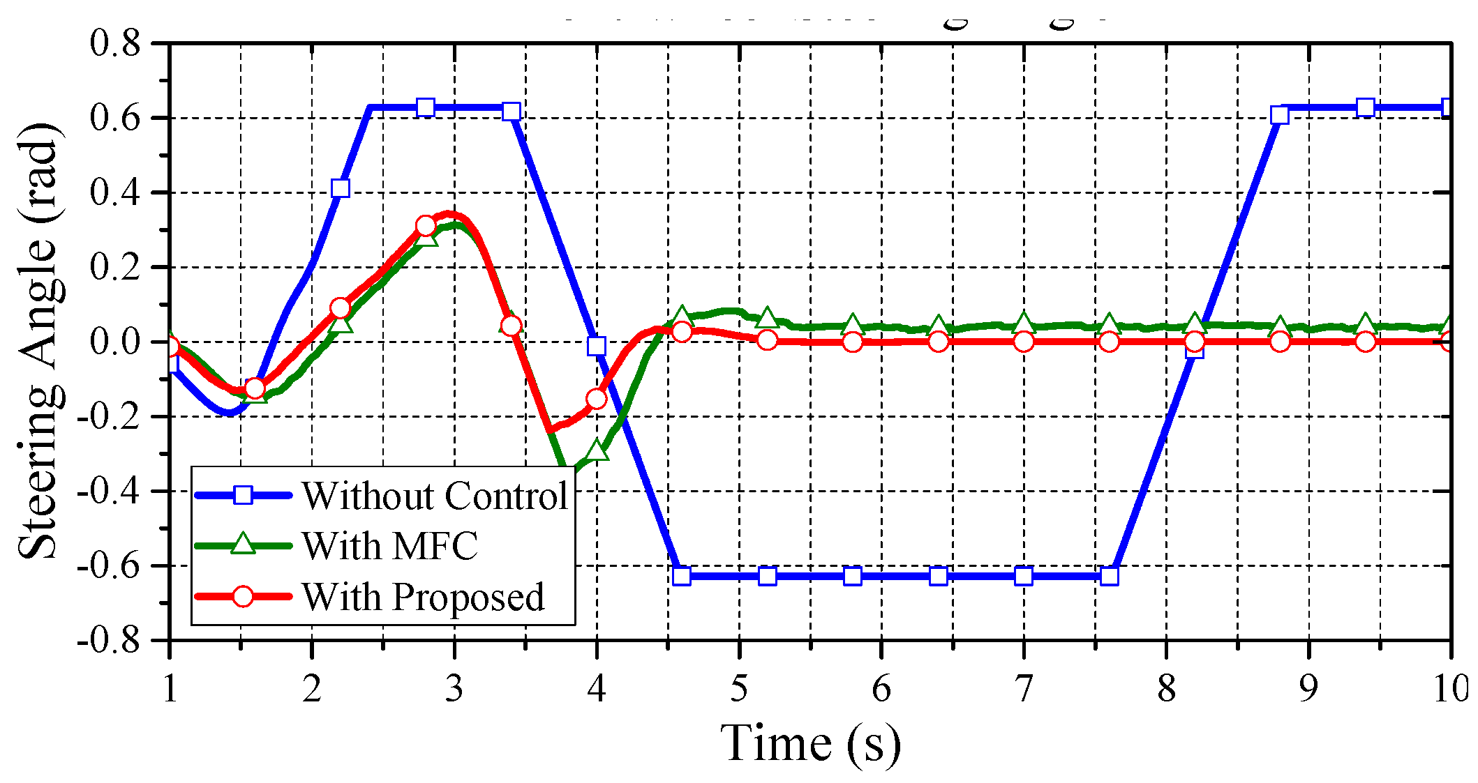
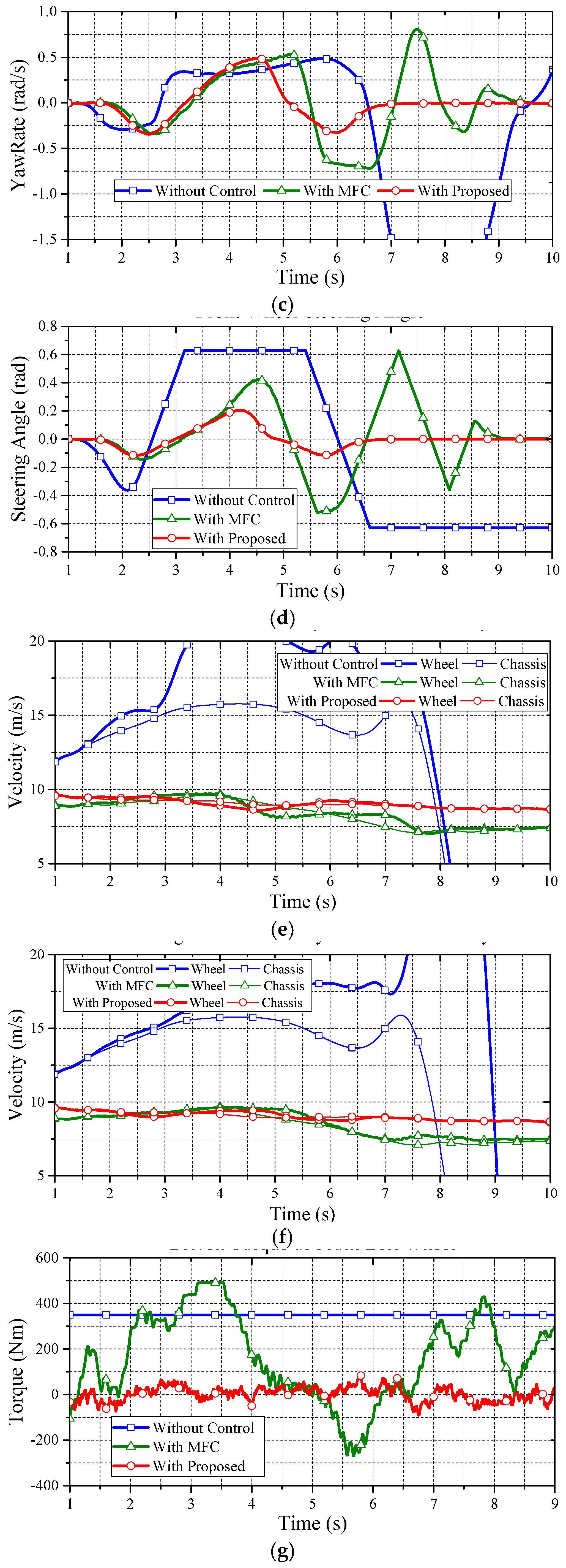
Figure 10 shows the yaw rate of the vehicle in the DLC test. As can be seen in this figure, the vehicle without control presents a largish oscillatory response, which means a poor handling performance. Only the proposed data fusion approach with PI compensation can achieve a good dynamic response on yaw rate. Based on Figure 9, the proposed approach can lead the vehicle back to a straight driving path with zero yaw rate in a short time. This is because the achieved wheel slip control ensures longitudinal and lateral tire force, which enhances the yaw stability on slippery road surfaces. Figure 11 reveals the front wheel steering angle of the DLC test. Note that the reduction ratio of the steering angle between the operator and front wheels is 20:1. As can be seen in this test, only the proposed approach can nimbly steer the vehicle through the DLC with nimble turning. The MFC and non-control cases both reach the maximum wheel steering angle (i.e., 36°) and cause a saturating deterioration.
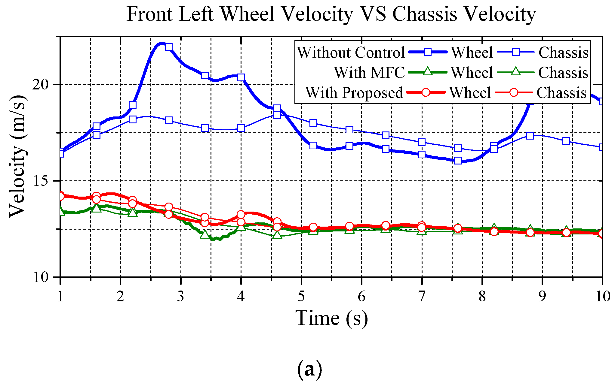
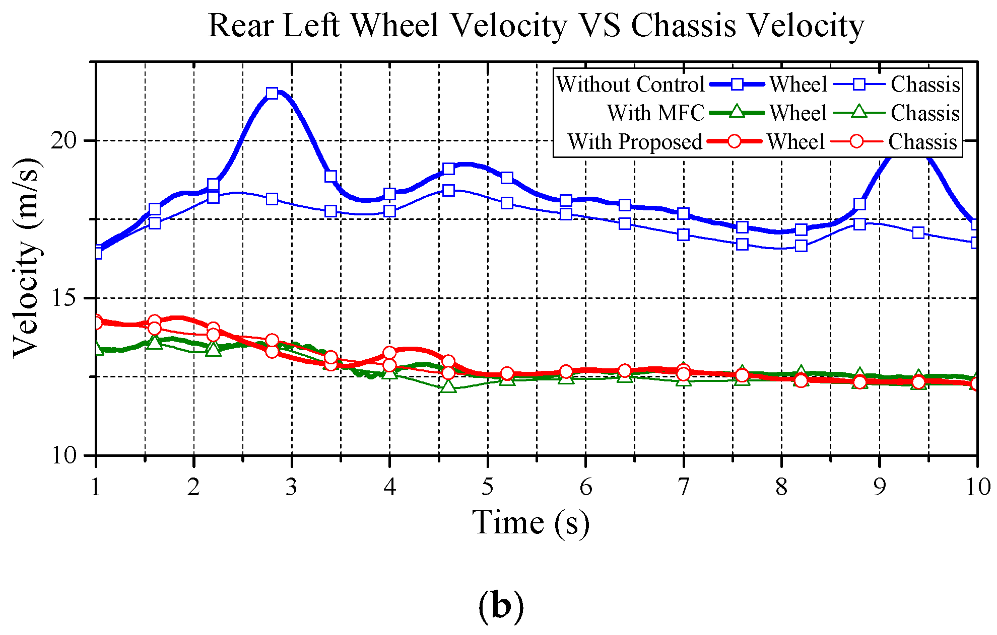
Figure 12 illustrates the comparisons of wheel velocity and chassis velocity. As seen in this figure, the proposed approach has a reliable performance on wheel slip suspression. Basically, without control, the actual wheel acceleration cannot track the reference acceleration of each wheel center, and the vehicle accelerates and decelerates drastically on the curve track. Consequently, the vehicle without control shows an apparent wheel slip. However, by reducing the difference between the actual and the reference accelerations, the vehicle with the proposed control can restrain the wheel slip effectively. Note that, in Figure 12, the MFC approach clearly prevents wheel slip by decreasing vehicle speed. Hence, although the MFC approach can suppress wheel slip, the tradeoff is the loss of kinetic energy; thus, the MFC approach, then, does not have a good dynamic performance due to the lack of driving torque.
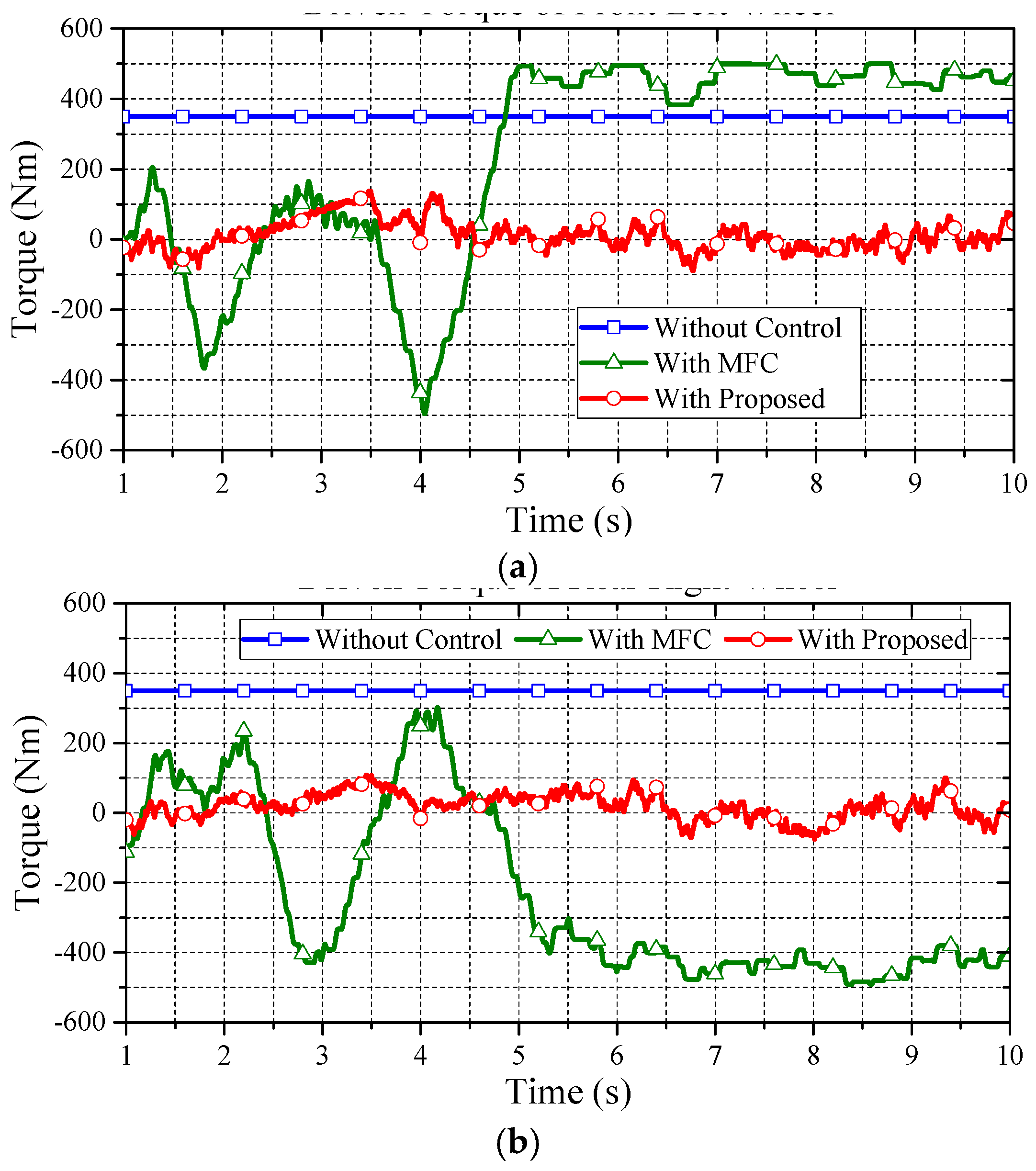
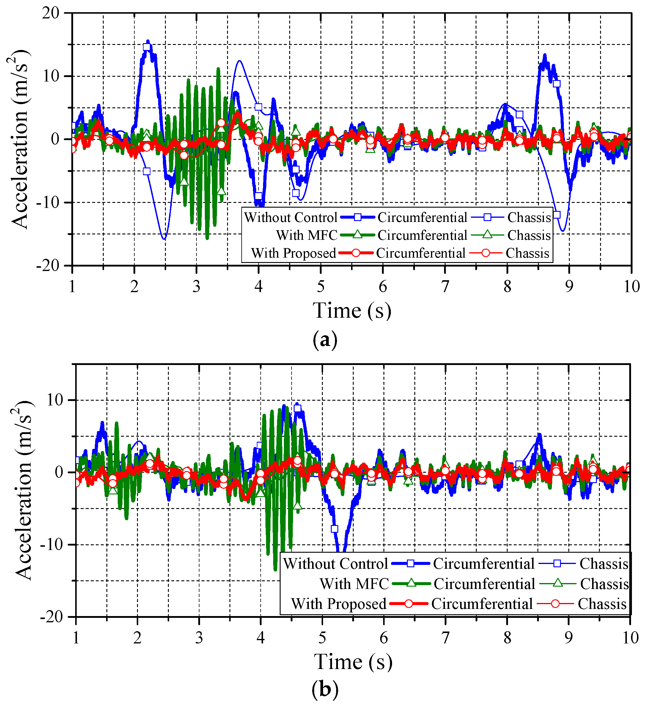
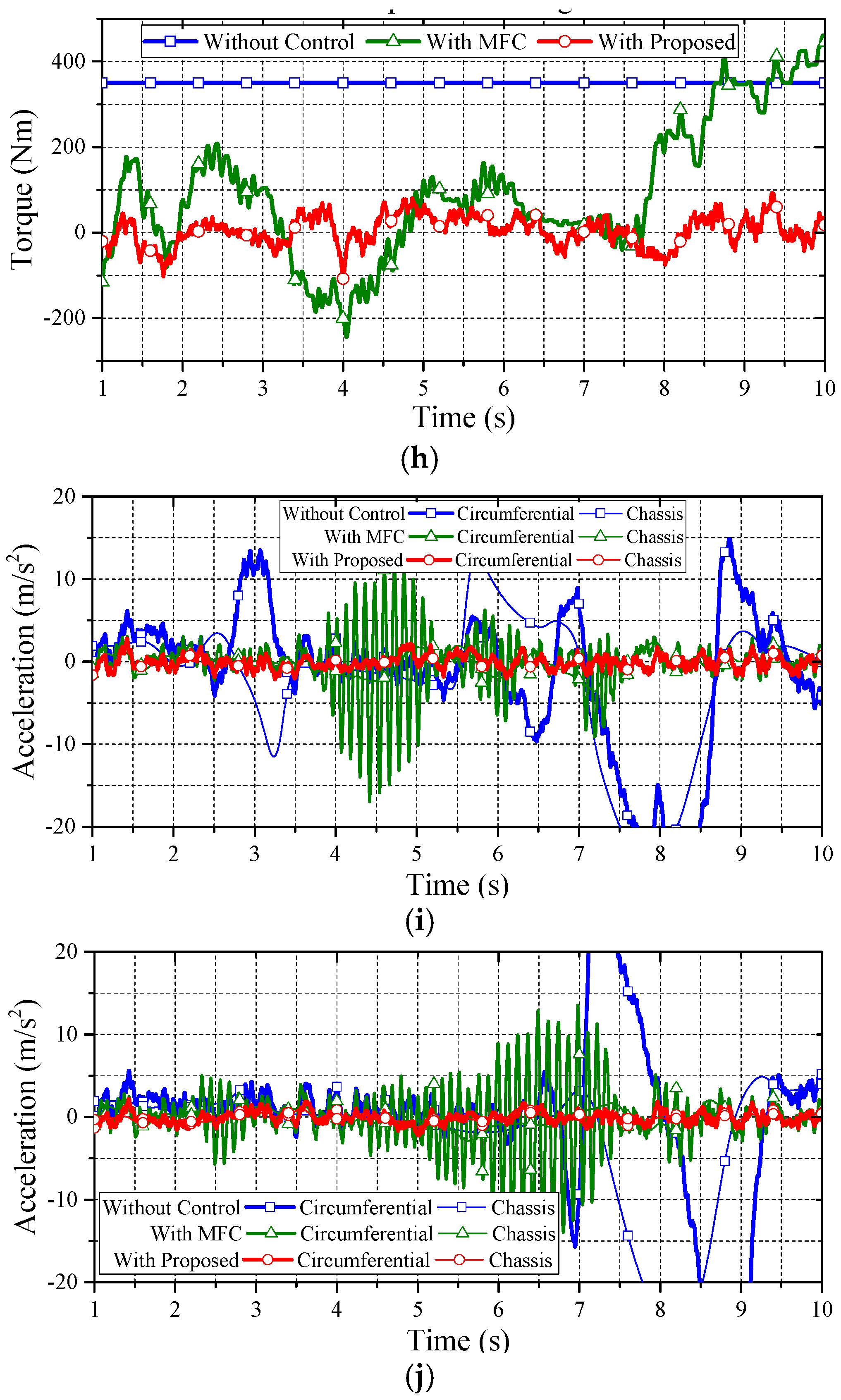
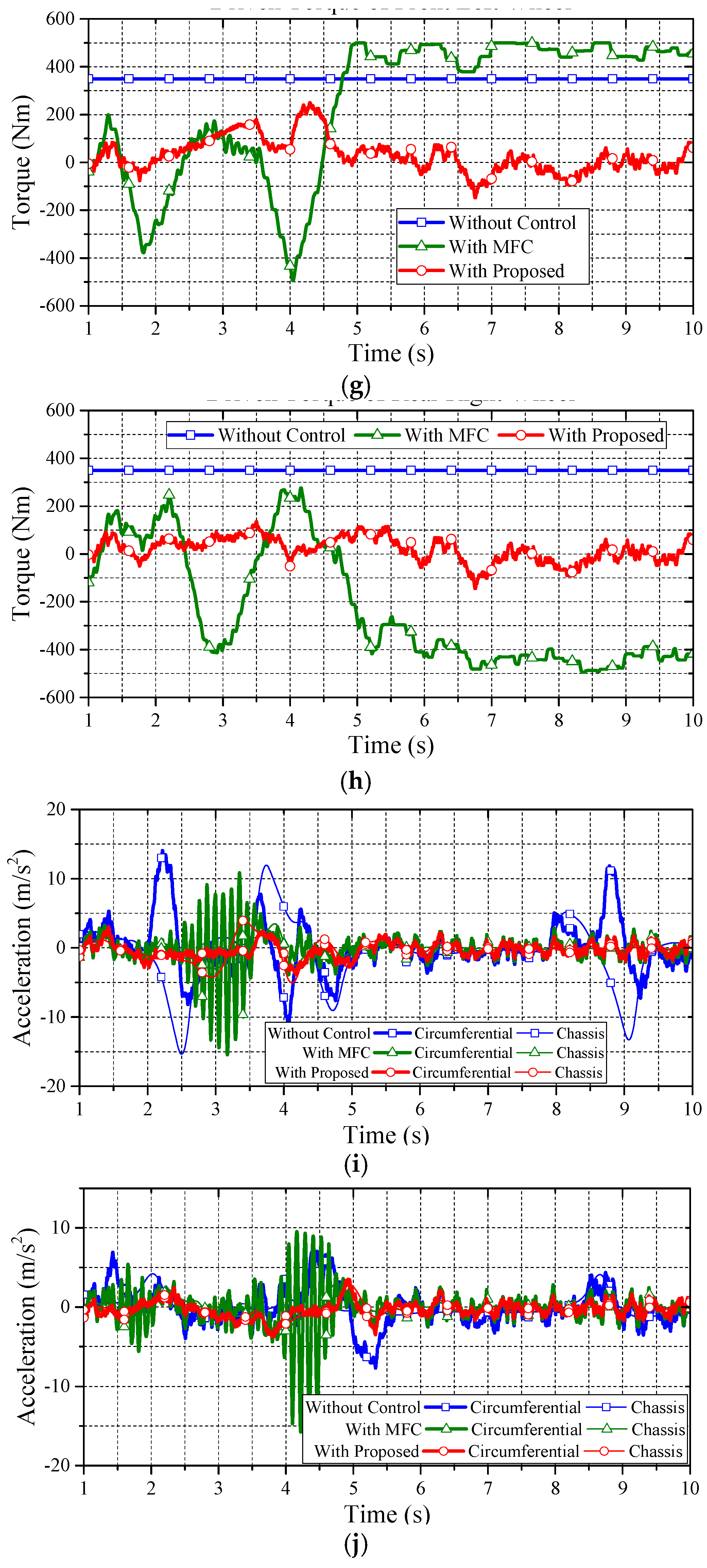
Under the DLC test, Figure 13 shows the comparisons of driving torque on the front wheels. Note that the vehicle with MFC makes a right turn at 3.5 s, which increases the wheel speed of the front left wheel. We know why the vehicle makes a right turn at 3.5 s because, in Figure 10, the front wheel steering angle shows the steering angle is at the peak value and starts to decline to a negative value. This means that the vehicle starts to make a right turn from the maximum left steering angle in the DLC. For the case of without control, the vehicle splits from the DLC trajectory and falls into an unstable situation. The vehicle with MFC makes a right turn at 4.3 s trying to correct the trajectory back to a straight line. At this time, the front left wheel suddenly appears to have a faster speed than the vehicle speed. Hence, the MFC mechanism starts to prevent “skidding” and suppresses the torque of the front left wheel. This sudden compensation causes a counterclockwise yaw-moment and obstructs the vehicle from making a right turn to return to driving in a straight line. On the other hand, the driver also seeks to quickly control the vehicle to return it to a straight line. The consequence results in a sizable curved line change, which renders the vehicle unable to return to a straight line. Figure 14 shows the comparisons of circumferential and chassis acceleration on the front wheels. Evidently, the proposed approach has less discrepancy in the dynamic test.
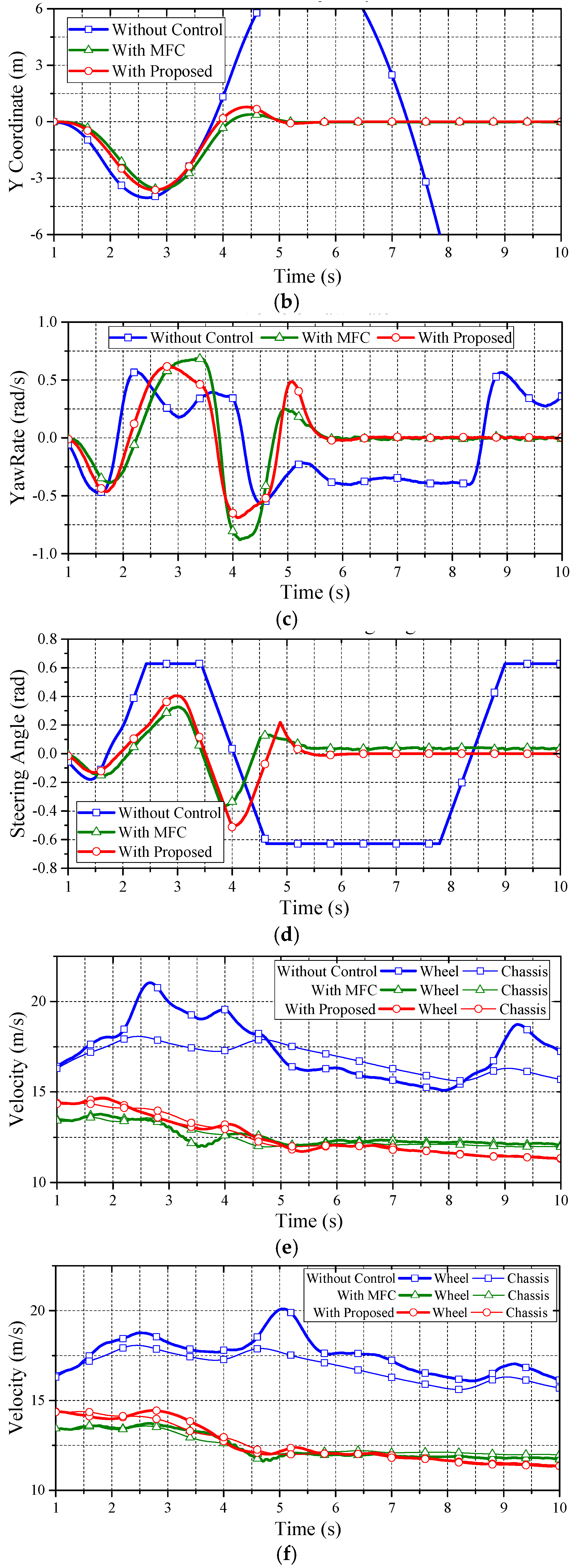
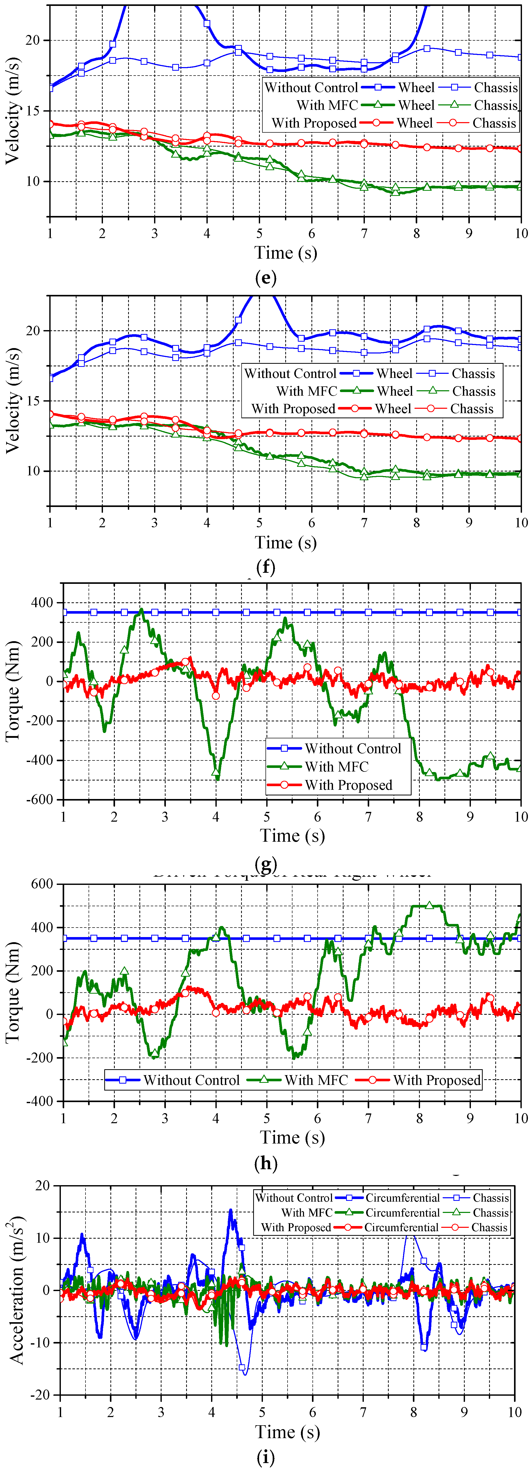
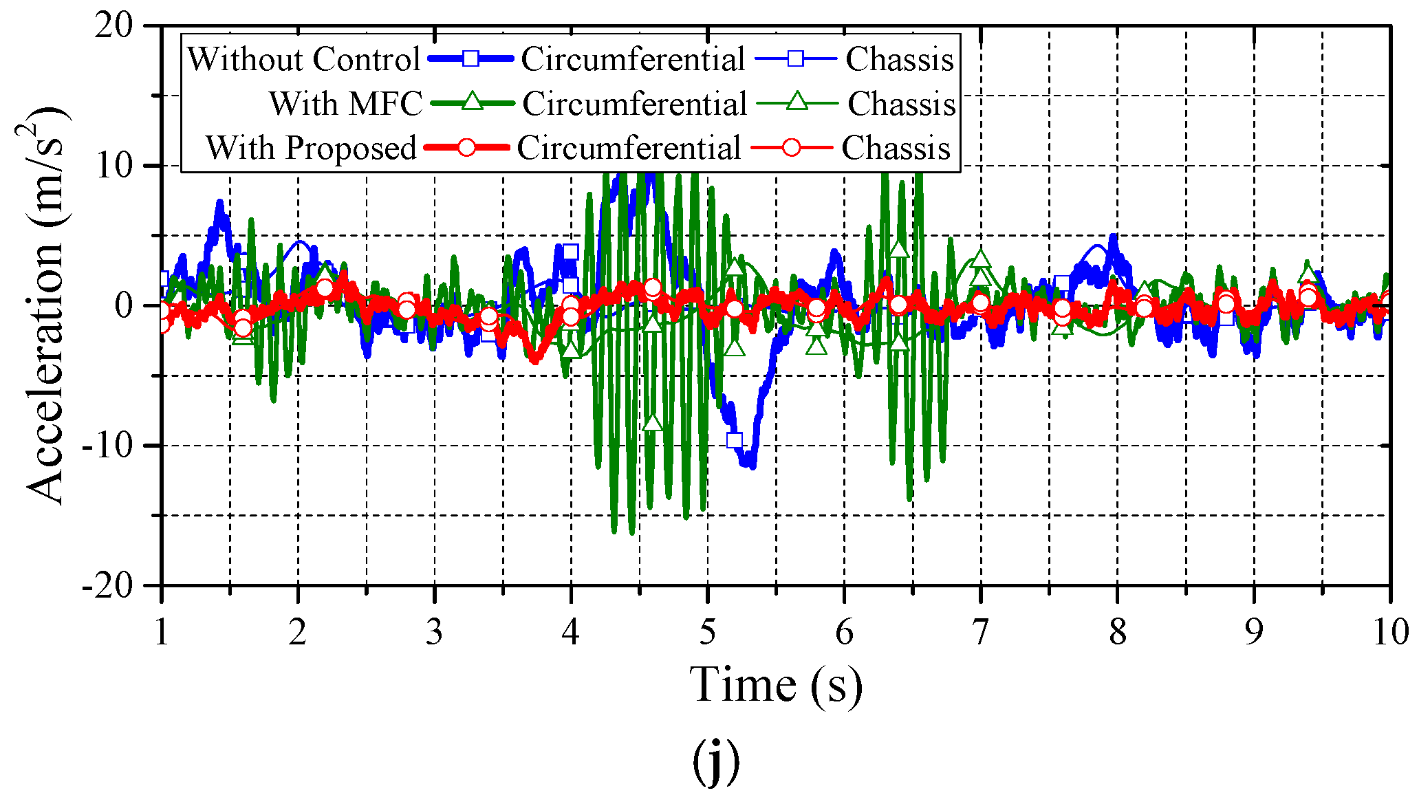
Figure 15 shows the comparative simulation with the same vehicle on a low friction road (μ = 0.45) for the second test. The results are revealed as follows. Compared to the MFC counterpart, the proposed approach can assist the driver in steering the vehicle. It does not disturb the driver or upper motion control unit, thus further guaranteeing driving stability.
Figure 16 illustrates the third simulation for robustness evaluation. This evaluation is performed under the DLC test with a heavier vehicle mass of 1939 kg on a road friction coefficient of 0.8. The initial vehicle speed of this test is set to 54 km/h. The simulation results, which highlight that the proposed approach has achieved the claimed anti-slip performance not only on regular vehicle mass but also heavier ones, are as follows.
Figure 17 illustrates the evaluation of the DLC test on a lighter vehicle mass of 1589 kg. The testing road friction coefficient is set to 0.8. The initial vehicle speed of this test is set to 54 km/h. The simulation results also reveal that the proposed approach has the claimed anti-slip performance on lighter vehicles. Note that, in Figure 15, Figure 16 and Figure 17, three vehicle masses are evaluated, 1589 kg, 1789 kg, and 1939 kg, respectively. These scenarios stand for the case of one driver, one driver with two passengers, and one driver with four passengers. The simulation results reveal that the mass perturbation has deep influences on MFC.
In this study, two major indexes are applied for evaluations:
- (1)
- Slip suppression: The velocity difference between the vehicle and the wheels.
- (2)
- 2-Degree of Freedom (DOF) motion stabilization: The DLC test.
Based on the fair testing frameworks, Table 3 and Table 4 summarize the performance comparisons. As can be seen in the Table 3 and Table 4, the proposed approach shows a better performance than the MFC. To summarize, compared with MFC, the proposed approach for wheel slip control, which is based on Equation (11), can respond with good handling without interfering with the driver’s command or upper motion controller. Therefore, the proposed approach can assist and enhance the steering stability to the wheel slip control.
5. Conclusions
This paper has proposed a novel wheel slip control method for power decentralized electric vehicles by maintaining the wheel circumferential acceleration to track the reference accelerations of the wheel centers, which are obtained by a control mechanism. This mechanism, adopting the proposed data fusion algorithm based on classical rigid body dynamics, only needs fixed body parameters, i.e., the wheel base and wheel trend, and measurable information, including the chassis longitudinal and lateral accelerations, and the vehicle yaw rate, to synthesize the reference value. Thus, compared with those methods based on model and wheel slip ratio, the proposed control method is more robust, regardless of the driving state or variation in vehicle mass. Compared with the non-control and MFC cases, the proposed approach is a feasible method to effectively maintain vehicle stability.
Acknowledgments
This work was mainly supported by “the Fundamental Research Funds for the Central Universities” of China, under projects No. 30915011305 and No. 30915118802. Part of this work was supported by the Ministry of Science and Technology (MOST) of Taiwan, under projects MOST 104-2221-E-024-008 and MOST 104-2218-E-006-026. The authors would like to thank the Associate Editor and the anonymous reviewers for their valuable and helpful suggestions that led to significant improvements of this paper.
Author Contributions
Dejun Yin, Nan Sun, and Danfeng Shan initiated and discussed the research problem; Jia-Sheng Hu conceived and developed the methods; Nan Sun and Danfeng Shan performed the simulations; Jia-Sheng Hu analyzed the data; and Dejun Yin and Jia-Sheng Hu prepared and wrote the paper.
Conflicts of Interest
The authors declare no conflict of interest.
References
- Paul, D.; Velenis, E.; Cao, D.; Dobo, T. Optimal μ-estimation based regenerative braking strategy for an AWD HEV. IEEE Trans. Transp. Electrif. 2017, 3, 249–258. [Google Scholar] [CrossRef]
- Itani, K.; De Bernardinis, A.; Khatir, Z.; Jammal, A.; Oueidat, M. Regenerative braking modeling, control, and simulation of a hybrid energy storage system for an electric vehicle in extreme conditions. IEEE Trans. Transp. Electrif. 2016, 2, 465–479. [Google Scholar] [CrossRef]
- Yin, D.; Hu, J.-S. Active approach to electronic stability control for front-wheel drive in-wheel motor electric vehicles. Int. J. Autom. Technol. 2014, 15, 979–987. [Google Scholar] [CrossRef]
- Hu, J.-S.; Lin, X.-C.; Yin, D.; Hu, F.-R. Dynamic motion stabilization for front-wheel drive in-wheel motor electric vehicles. Adv. Mech. Eng. 2015, 7, 1–11. [Google Scholar] [CrossRef]
- Yin, D.; Shan, D.; Hu, J.-S. A novel electronic differential system for power decentralized electric vehicles. Appl. Sci. 2017, 7. [Google Scholar] [CrossRef]
- Zhao, H.; Ren, B.; Chen, H.; Deng, W. Model predictive control allocation for stability improvement of four-wheel drive electric vehicles in critical driving condition. IET Control Theory Appl. 2015, 9, 2688–2696. [Google Scholar] [CrossRef]
- Hu, C.; Wang, R.; Yan, F. Integral sliding mode-based composite nonlinear feedback control for path following of four-wheel independently actuated autonomous vehicles. IEEE Trans. Transp. Electrif. 2016, 2, 221–230. [Google Scholar] [CrossRef]
- Yin, D.; Oh, S.; Hori, Y. A novel traction control for EV based on maximum transmissible torque estimation. IEEE Trans. Ind. Electron. 2009, 56, 2086–2094. [Google Scholar]
- Hu, J.-S.; Yin, D.; Hori, Y.; Hu, F.-R. Electric vehicle traction control: A new MTTE methodology. IEEE Ind. Appl. Mag. 2012, 18, 23–31. [Google Scholar] [CrossRef]
- Hu, J.-S.; Yin, D.; Hori, Y. Fault-tolerant traction control of electric vehicles. Control Eng. Pract. 2011, 19, 204–213. [Google Scholar] [CrossRef]
- Zhang, H.; Zhang, G.; Wang, J. Sideslip angle estimation of an electric ground vehicle via finite-frequency H∞ approach. IEEE Trans. Transp. Electrif. 2016, 2, 200–209. [Google Scholar] [CrossRef]
- Suryanarayanan, S.; Tomizuka, M. Appropriate sensor placement for fault-tolerant lane-keeping control of automated vehicles. IEEE/ASME Trans. Mech. 2007, 12, 465–471. [Google Scholar] [CrossRef]
- Suzuki, T.; Fujimoto, H. Slip ratio estimation and regenerative brake control without detection of vehicle velocity and acceleration for electric vehicle at urgent brake-turning. In Proceedings of the 2010 11th IEEE International Workshop on Advanced Motion Control, Nagaoka, Japan, 21–24 March 2010. [Google Scholar]
- Xu, G.; Xu, K.; Zheng, C.; Zahid, T. Optimal operation point detection based on force transmitting behavior for wheel slip prevention of electric vehicles. IEEE Trans. Intell. Transp. Syst. 2016, 17, 481–490. [Google Scholar] [CrossRef]
- Hori, Y. Future vehicle driven by electricity and control-research on four-wheel-motored “UOT electric march II”. IEEE Trans. Ind. Electron. 2004, 51, 954–962. [Google Scholar] [CrossRef]
- Hu, J.-S.; Wang, Y.; Fujimoto, H.; Hori, Y. Robust yaw stability control for in-wheel motor electric vehicles. IEEE/ASME Trans. Mech. 2017. [Google Scholar] [CrossRef]
- Akiba, T.; Shirato, R.; Fujita, T.; Tamura, J. A study of novel traction control method for electric motor driven vehicle. In Proceedings of the 2007 Power Conversion Conference, Nagoya, Japan, 2–5 April 2007. [Google Scholar]
- De Castro, R.; Araújo, R.E.; Freitas, D. Wheel slip control of EVs based on sliding mode technique with conditional integrators. IEEE Trans. Ind. Electron. 2013, 60, 3256–3271. [Google Scholar] [CrossRef]
- Hsiao, T. Robust wheel torque control for traction/braking force tracking under combined longitudinal and lateral motion. IEEE Trans. Intell. Transp. Syst. 2015, 16, 1335–1347. [Google Scholar] [CrossRef]
- Cabrera, J.A.; Castillo, J.J.; Carabias, E.; Ortiz, A. Evolutionary optimization of a motorcycle traction control system based on fuzzy logic. IEEE Trans. Fuzzy Syst. 2015, 23, 1594–1607. [Google Scholar] [CrossRef]
- Lin, W.-S.; Chang, L.-H.; Yang, P.-C. Adaptive critic anti-slip control of wheeled autonomous robot. IET Control Theory Appl. 2007, 1, 51–57. [Google Scholar] [CrossRef]
- Ivanov, V.; Savitski, D.; Shyrokau, B. A survey of traction control and antilock braking systems of full electric vehicles with individually controlled electric motors. IEEE Trans. Veh. Technol. 2015, 64, 3878–3896. [Google Scholar] [CrossRef]
- Wu, X.; Ma, C.; Xu, M.; Zhao, Q.; Cai, Z. Single-parameter skidding detection and control specified for electric vehicles. J. Frankl. Inst. 2015, 352, 724–743. [Google Scholar] [CrossRef]
- Mi, C.; Masrur, A.; Gao, W. Modern Hybrid Electric Vehicles; Wiley: London, UK, 2011. [Google Scholar]
- Savaresi, S.M.; Tanelli, M. Active Braking Control Systems Design for Vehicles; Springer: London, UK, 2010. [Google Scholar]
- ISO 3888-2:2011. Passenger Cars—Test Track for a Severe Lane-change Manoeuvre—Obstacle Avoidance; International Organization for Standardization: Geneva, Switzerland, 2011. [Google Scholar]
Figure 1.
Longitudinal dynamics of one-wheel vehicle model.
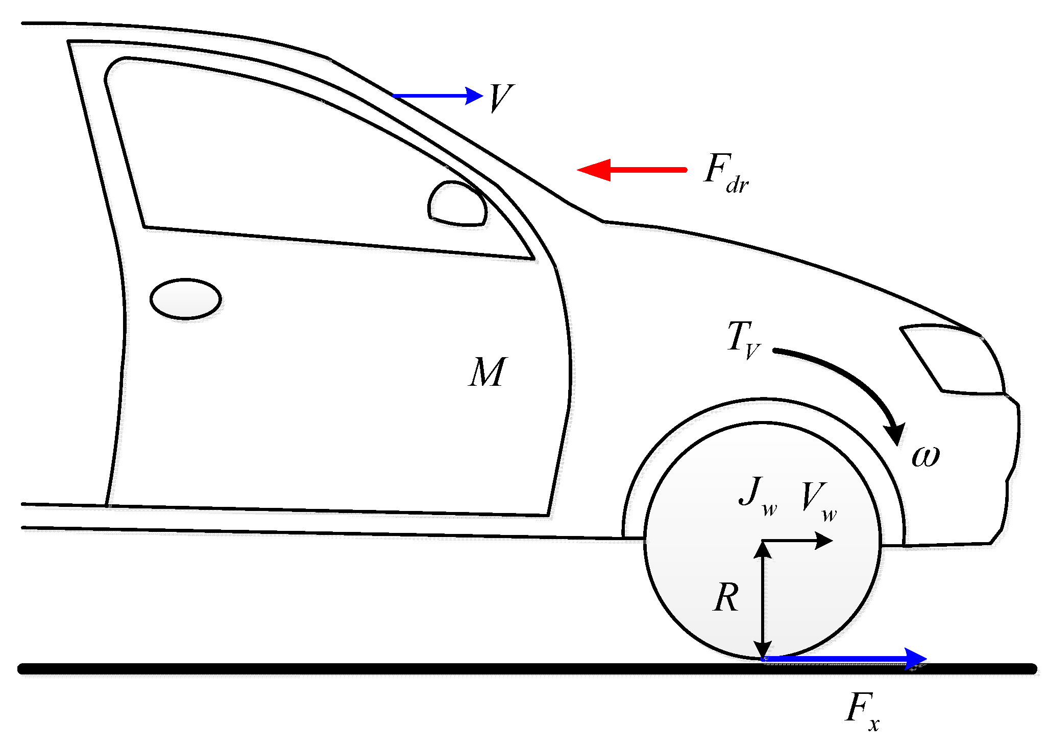
Figure 2.
Vehicle model used for data fusion analysis.

Figure 3.
Proposed wheel slip control scheme (based on data fusion).

Figure 4.
Equivalent model of the proposed control.

Figure 5.
Reference for front wheel steering angle.

Figure 6.
Simulation results of data fusion: (a) longitudinal acceleration of front left wheel; (b) longitudinal acceleration of front right wheel; (c) lateral acceleration of front left wheel; and (d) lateral acceleration of front right wheel.
Figure 6.
Simulation results of data fusion: (a) longitudinal acceleration of front left wheel; (b) longitudinal acceleration of front right wheel; (c) lateral acceleration of front left wheel; and (d) lateral acceleration of front right wheel.

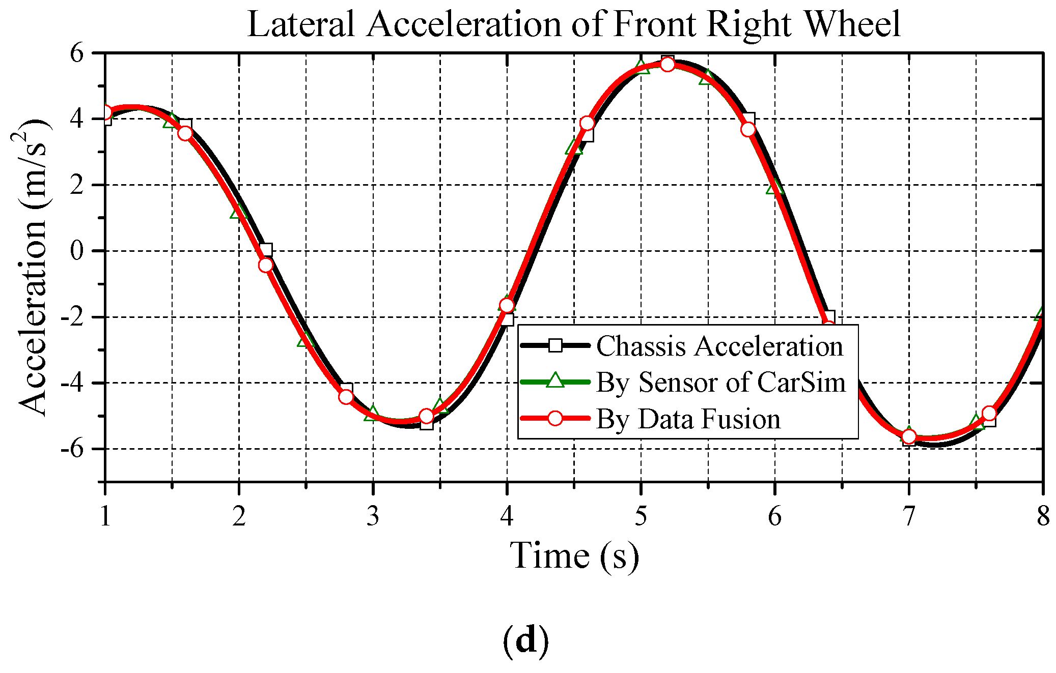
Figure 7.
Simulation results of data fusion: (a) reference for front wheel steering angle; (b) longitudinal acceleration of front left wheel; (c) longitudinal acceleration of rear right wheel; (d) lateral acceleration of front left wheel; and (e) lateral acceleration of rear right wheel.
Figure 7.
Simulation results of data fusion: (a) reference for front wheel steering angle; (b) longitudinal acceleration of front left wheel; (c) longitudinal acceleration of rear right wheel; (d) lateral acceleration of front left wheel; and (e) lateral acceleration of rear right wheel.


Figure 8.
MFC control scheme.

Figure 9.
Vehicle trajectory.

Figure 10.
Yaw rate of vehicle.
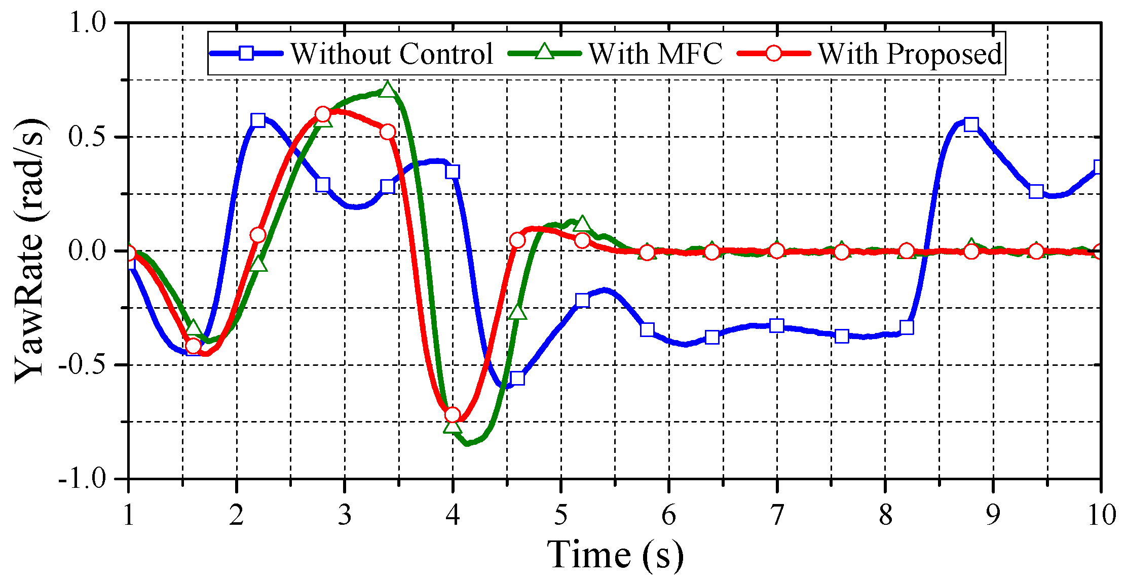
Figure 11.
Front wheel steering angle.

Figure 12.
Wheel velocity vs. chassis velocity: (a) front left wheel; and (b) rear right wheel.


Figure 13.
Driven torque of each wheel for DLC: (a) front left wheel; and (b) rear right wheel.

Figure 14.
Circumferential vs. chassis acceleration of each wheel: (a) front left wheel; and (b) rear right wheel.
Figure 14.
Circumferential vs. chassis acceleration of each wheel: (a) front left wheel; and (b) rear right wheel.

Figure 15.
Comparative simulation on low friction road for second test: (a) vehicle trajectory; (b) displacement in Y-direction; (c) vehicle yaw rate; (d) front wheel steering angle; (e) front left wheel velocity vs. chassis velocity; (f) rear right wheel velocity vs. chassis velocity; (g) driven torque of front left wheel; (h) driven torque of rear right wheel; (i) circumferential vs. chassis acceleration of front left wheel; and (j) circumferential vs. chassis acceleration of rear right wheel.


Figure 16.
Evaluation on heavier vehicle mass for third test: (a) vehicle trajectory; (b)displacement in Y-direction; (c) vehicle yaw rate; (d) front wheel steering angle; (e) front left wheel velocity vs. chassis velocity; (f) rear right wheel velocity vs. chassis velocity; (g) driven torque of front left wheel; (h) driven torque of rear right wheel; (i) circumferential vs. chassis acceleration of front left wheel; and (j) circumferential vs. chassis acceleration of rear right wheel.


Figure 17.
Evaluation on lighter vehicle mass for DLC: (a) vehicle trajectory; (b) displacement in Y-direction; (c) vehicle yaw rate; (d) front wheel steering angle; (e) front left wheel velocity vs. chassis velocity; (f) rear right wheel velocity vs. chassis velocity; (g) driven torque of front left wheel; (h) driven torque of rear right wheel; (i) circumferential vs. chassis acceleration of front left wheel; and (j) circumferential vs. chassis acceleration of rear right wheel.


Table 1.
Parameter definitions.
| Symbol | Definition |
|---|---|
| Vehicle mass (for Quarter Car) | |
| Wheel inertia | |
| Driving torque | |
| Driving resistance | |
| Friction force | |
| Normal force | |
| Chassis speed | |
| Wheel speed (Circumferential Speed) | |
| Wheel rotation speed | |
| Wheel radius | |
| Friction coefficient |
Table 2.
Vehicle specification.
| Sprung Mass | 1429 kg |
|---|---|
| Unsprung mass | 360 kg |
| Width D | 1565 mm |
| Height of CM | 670 mm |
| Wheelbase L | 2619 mm |
| Front wheel base | 1050 mm |
| Rear wheel base | 1569 mm |
| Unloaded wheel radius | 394 mm |
| Wheel inertia | 0.9 kg·m2 |
Table 3.
Vehicle specification maximum position error in Y-direction (Unit: m).
| Approach/Scenario | Low Friction | High Friction | Lighter Weight | Heavier Weight |
|---|---|---|---|---|
| Without Control | 5.5 | 3.5 | 7 | 7 |
| MFC Control | 0.8 | 0.5 | 0.8 | 0.3 |
| Proposed Control | 0.2 | 0.5 | 0.6 | 0.6 |
Table 4.
Total time for vehicle in the longitudinal path (Unit: s).
| Approach/Scenario | Low Friction | High Friction | Lighter Weight | Heavier Weight |
|---|---|---|---|---|
| MFC Control | 9 | 5 | 8.5 | 5.5 |
| Proposed Control | 6 | 5 | 4.5 | 5.5 |
© 2017 by the authors. Licensee MDPI, Basel, Switzerland. This article is an open access article distributed under the terms and conditions of the Creative Commons Attribution (CC BY) license (http://creativecommons.org/licenses/by/4.0/).
Share and Cite
MDPI and ACS Style
Yin, D.; Sun, N.; Shan, D.; Hu, J.-S. A Multiple Data Fusion Approach to Wheel Slip Control for Decentralized Electric Vehicles. Energies 2017, 10, 461. https://doi.org/10.3390/en10040461
AMA Style
Yin D, Sun N, Shan D, Hu J-S. A Multiple Data Fusion Approach to Wheel Slip Control for Decentralized Electric Vehicles. Energies. 2017; 10(4):461. https://doi.org/10.3390/en10040461
Chicago/Turabian StyleYin, Dejun, Nan Sun, Danfeng Shan, and Jia-Sheng Hu. 2017. "A Multiple Data Fusion Approach to Wheel Slip Control for Decentralized Electric Vehicles" Energies 10, no. 4: 461. https://doi.org/10.3390/en10040461
Note that from the first issue of 2016, this journal uses article numbers instead of page numbers. See further details here.