
Stability Analysis of DC Distribution Systems with Droop-Based Charge Sharing on Energy Storage Devices


Department of Electrical and Computer Engineering, University of Patras, 26504 Patras, Greece
*
Author to whom correspondence should be addressed.
Energies 2017, 10(4), 433; https://doi.org/10.3390/en10040433
Submission received: 30 September 2016
/
Revised: 11 January 2017
/
Accepted: 16 March 2017
/
Published: 27 March 2017
(This article belongs to the Special Issue Microgrids 2016)
Abstract
:Direct current (DC) distribution systems and DC microgrids are becoming a reliable and efficient alternative energy system, compatible with the DC nature of most of the distributed energy resources (DERs), storage devices and loads. The challenging problem of redesigning an autonomous DC-grid system in view of using energy storage devices to balance the power produced and absorbed, by applying simple decentralized controllers on the electronic power interfaces, is investigated in this paper. To this end, a complete nonlinear DC-grid model has been deployed that includes different DC-DERs, two controlled parallel battery branches, and different varying DC loads. Since many loads in modern distribution systems are connected through power converters, both constant power loads and simple resistive loads are considered in parallel. Within this system, suitable cascaded controllers on the DC/DC power converter interfaces to the battery branches are proposed, in a manner that ensures stability and charge sharing between the two branches at the desired ratio. To achieve this task, inner-loop current controllers are combined with outer-loop voltage, droop-based controllers. The proportional-integral (PI) inner-loop current controllers include damping terms and are fully independent from the system parameters. The controller scheme is incorporated into the system model and a globally valid nonlinear stability analysis is conducted; this differs from small-signal linear methods that are valid only for specific systems, usually via eigenvalue investigations. In the present study, under the virtual cost of applying advanced Lyapunov techniques on the entire nonlinear system, a rigorous analysis is formulated to prove stability and convergence to the desired operation, regardless of the particular system characteristics. The theoretical results are evaluated by detailed simulations, with the system performance being very satisfactory.
1. Introduction
The traditional structure of power systems has dramatically changed to involve modern active distribution and microgrid-based schemes. This is mainly due to environmental concerns, and the requirement of reducing CO2 emissions, a task that renewable energy sources such as wind and photovoltaic (PV) power systems can effectively satisfy by providing a large part of “clean” power production. At the consumer side, other innovations such as electric vehicles (EVs) can also play a key role [1]. In light of this evolution, and due to the fact that many of the distributed energy resources (DERs) are or may be DC devices, and since DC-supplied loads are continuously increased, adoption of DC distribution systems and DC microgrids is now feasible. Furthermore, since most of the DERs and DC loads are locally connected through a DC/DC power electronic converter, this provides a significant opportunity for locally controlling the power absorbed or injected at desired rates. In such a scheme, the superiority of DC distribution over AC distribution is efficiency, reliability and economy of DC distribution, since intermediate DC/AC/DC conversion stages are eliminated [2]. Emerging new sources and loads such as batteries, PVs, data centers, office and home appliances (such as computers and printers), as well as different industrial applications (e.g., electrochemical processing) are natively DC-supplied while others such as industrial drives and traction are implemented by using controlled DC sources via DC/AC power conversion (e.g., inverted fed AC motors) [3,4]. Finally, as reactance has little effect on DC transmission, and reactive power does not exist, cables can carry more power with reduced losses.
A challenging issue for DC distribution and DC microgrid deployment is to examine the system for stability due to the stochastic and intermittent nature of most of the DERs, and the unknown variations of the loads. In contrary to AC power systems, where stability criteria are established and extensively analyzed, the stability of DC grids is still under investigation. Instabilities caused by DC/DC converters have been analyzed by considering these devices as individual components [5], with the stable region determined by using either appropriate input filter designs for the converter [6], or impedance and Rough-Hurwitz criteria [7,8]. However, as shown in [9,10], the situation where stability is guaranteed for each individual converter by a suitable controller scheme, is not sufficient for an integrated converter-dominated distribution system to operate in the stable region.
Even though droop-controlled schemes are implemented in each electronic power component of a microgrid, instability problems can appear as a result of the tight and separate regulation of the controllers [11]. It is noted that droop-control in the case of DC distribution grids conventionally includes a regulator that provides an output voltage correction that is inversely proportional to the output power in accordance to the droop coefficient [12]. The droop-controller objective is to generate the voltage reference signal of a DER in a manner that compensates instantaneous mismatch between scheduled power, and power as demanded by the loads. The values of the droop coefficients have a profound effect on system stability and current sharing accuracy. In general, the higher the droop coefficients, the more damped the system is, and better current sharing accuracy is achieved, although a trade-off is needed in order to maintain the voltage deviations at acceptable levels [13]. Assuming that droop control is slower than the primary outer-loop voltage control, and much slower than the inner-loop current control, and ignoring fast dynamics and using small signal analysis, it is shown [12] that stable operation of the DC-grid system is ensured. However, this analysis is based on the eigenvalue assignment, which is unfortunately not a general approach, as it depends on the specific system parameter values [12,14,15]. Also, in [16], small signal analysis for DC microgrids has been addressed with all DERs and loads considered as first-order systems. In this study, all the loads have been considered only as constant power loads [17,18,19], a fact that is in contradiction with the results presented in [20], where it has been shown that a significant portion of DC loads should be modeled as constant impedance loads. Other small signal stability studies have been conducted for shipboard [21] and aircraft [22] electric network applications.
The wide expected penetration of EVs in the near future seems to be the main factor behind DC distribution and DC microgrid designs. Beyond the long-term management of charging the EV batteries at off-peak hours in order to achieve low cost pricing [1], short-term solutions are already under consideration. Fast or ultra-fast DC charge infrastructures have been proposed by the industry [23], with the aim of enabling safe charging in the shortest possible time. The task of reducing the maximum charging duration to under 10 minutes for a battery set to reach the 80% of its nominal state of charge (SoC) seems to be feasible. Therefore, it becomes evident that a need exists for deploying in cities a DC-grid that is capable of meeting power requirements. Also, as shown recently [24,25], when batteries are used as storage devices, this scheme will be used to regulate both power sharing and the SoC rate of the storage device regardless of variations on load and generation. In all the aforementioned methods of analysis, fast primary level inner-loop controller dynamics are not taken into account. Since stability for a droop-driven system is conducted under the assumption that the inner-loop control achieves convergence of the actual output to its reference, a much more robust design is needed, and the system should be analyzed for its stability with inclusion of fast controller dynamics.
In this paper, the problem of balancing each time instant the power in an autonomous DC microgrid system is investigated, with this task to be implemented exclusively by two different fully controlled energy storage devices. An EV charging/discharging line can represent a storage system, and as it is the only responsible part of the DC-grid for balancing the power, it is possible for all the other DERs to operate at any predefined power level. Simultaneously, power sharing is achieved between the storage devices in accordance to the droop characteristics used for this reason. To investigate such a characteristic DC distribution system, this is modeled to include several DERs, different varying loads with two parts, a constant power load in parallel to a pure resistive, and two battery charging branches. The DC resistive load component can change during operation, while the constant power load part is considered to be a constant current source that absorbs energy from the DC distribution system. This representation of the constant power load is adequate for all the loads connected via DC/DC or DC/AC converters. In modern distribution systems, these represent a significant portion of the total loads in DC networks, and since voltage deviation is not permitted to exceed some strict limits, it is feasible that these kinds of loads are modeled as constant current sources that absorb energy (negative current) from the DC-grid [26]. DERs are also considered to be current sources that operate at levels determined at each time instant by the injected power available. This means, for example, that a standard operation at the maximum power point (MPP) or an operation at a lower scheduled power level of a renewable energy source can be easily realized by inserting a varying multiplier ranging from zero to one. In our case, when constant power loads are connected at the DER bus, the current source actually represent the net power source as it is determined after subtracting the constant negative current absorbed. The two battery branches represent a fast charging branch and a slower charging one. Their dynamic models are included in detail where the DC distribution system is controlled through the duty-ratio inputs of each DC/DC converter interface between the branch and the DC-grid. Distribution lines between the buses are considered. On this system, cascaded control schemes are proposed with simple current controllers and DC power/voltage droop-based controllers used as fast inner-loop and slower outer-loop controllers, respectively. In order to further enhance the controller performance, a proportional-integral (PI) scheme has been proposed, wherein a damping term is added. A five-to-one power balance between the fast charging and the slow charging branch has been examined by using a five times greater droop coefficient for the first controller in order to achieve a five-to-one faster SoC rate at the first branch.
For design and analysis purposes, a model is developed that includes all the particular dynamics of the DC distribution system, together with inner-loop controller dynamics being carefully taken into account. Using the developed nonlinear model of the complete system, the input-to-state (ISS) property [27,28] of the entire system is firstly proven, while advanced Lyapunov-based techniques are applied to show closed-loop stability and convergence to a non-zero equilibrium. The proposed control design and analysis is of great significance in real-world applications, and constitutes the main contribution of the present work, since stable operation of a DC distribution system can be guaranteed with the fast dynamics of the system to converge to the equilibrium. On this basis, also the conventional analysis, as extensively mentioned in the literature (see for example [12]), with the droop-based outer controllers additionally incorporated, seems to be further valid for the entire closed-loop DC-grid system. Finally, the complete system performance and response has been extensively examined with simulation results, to fully verify the effectiveness of the proposed scheme. As indicated by the results, the desired power balance and battery charge sharing is well-achieved by the droop controllers.
2. System Modeling
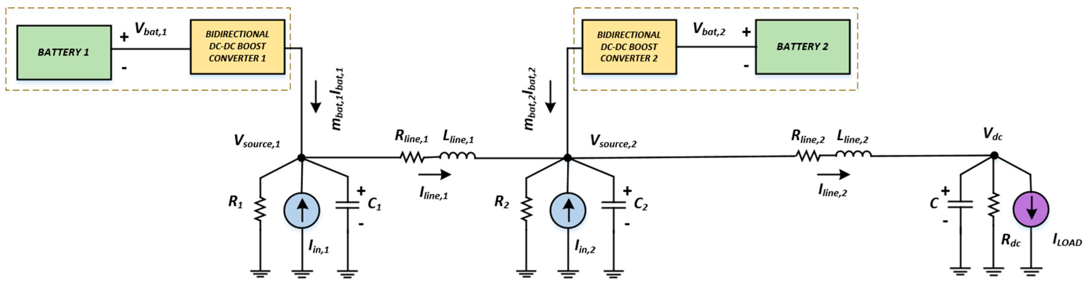
In modern distribution and microgrid systems, photovoltaics, fuel cells, storage devices, and small power plants, are commonly applied as distributed energy sources in structures that include controlled power electronic devices. Energy storage devices almost always have a bidirectional DC/DC boost converter as interface between the energy source and the storage unit. In the case of a DC microgrid in a stand-alone operation, the system should be capable of providing power to the consumers under a predefined voltage level, regardless of load and energy source changes. A complete DC autonomous microgrid, as depicted in Figure 1, is considered along with the detailed Li-ion battery model (Figure 2), and the proposed inner- and outer-loop current and voltage cascaded controllers are included.
In the next subsections, particular fast inner-loop controllers are firstly discussed and incorporated into the original system, since their influence on system dynamics and stability is essential. Subsequently, the system is completed with the slower outer-loop controllers, in a cascaded scheme, with their task to determine the inner-loop current command inputs.
For stability analysis and for the control design, the accurate model of a DC microgrid system, in stand-alone mode, is developed. Several DERs are considered, such as PV generators operating at their MPP, and these are represented by variable current sources, while the storage units are modeled as Li-ion batteries [29] with the bidirectional boost converters used as a power interface. Loads involving two parts, a constant power load in parallel to a pure resistive one, are considered to be connected to the common node via a distribution line. It is noted that the constant power load part is considered as a constant current source. The current source, connected at each DER bus, actually represents the net power source by subtracting the constant negative current absorbed by the local constant power loads.
Therefore, the entire model deployment is derived from the combination of the average converters models [30] and the other system component dynamics as follows:
where , are the batteries’ currents and , are the voltages on the resistors , respectively. , represent the initial voltage level values for each battery and depends on the type of the battery. , are the voltages at the points of connection of the multiple DC sources while and are the local resistive loads. , stand for the maximum current levels of each source while , stand for a coefficient with value ranges between 0 and 1 representing the operating situation of the source after taking into account the local constant power loads. For example, a value of 0.7 means that the source operates at 70% of its nominal value. Also, and stand for each converter duty-ratio signal, which represent the controlled inputs of the system. Finally, , represent the parameters of the connection lines, while stands for the voltage level at the load bus ( is the resistive part and is the constant power load).
3. The Proposed Control Scheme
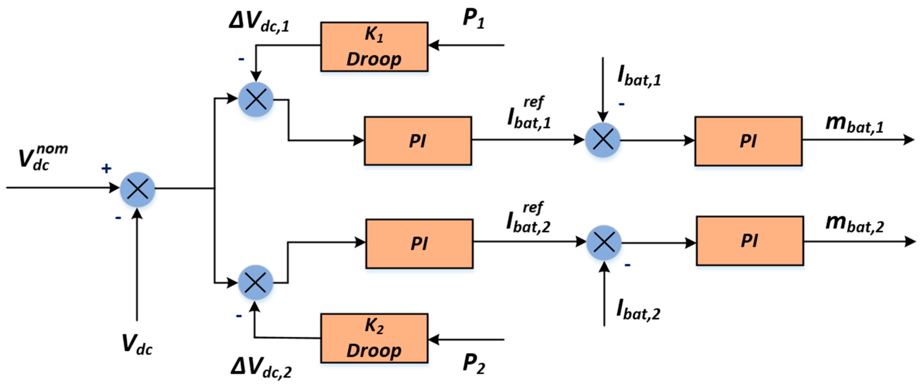
The proposed control scheme is designed according to a well-known cascaded mode, based on the time-scale separation principle. This principle permits the implementation of cascaded controllers consisting of an inner-loop PI current fast controller that regulates each bidirectional boost converter current at its reference value, while the reference value is produced by a pair of slow outer-loop PI controllers. In Figure 3, the block diagram of the proposed controller scheme is provided. In accordance to this scheme, the measured value of is initially compared with its nominal value, with the output feeding a couple of control paths corresponding to each storage unit branch controlled input, namely and , at each DC/DC boost converter. In each path, one can see the droop-based correction of the command input to the slower outer-loop controller used to create the final reference command input for the inner-loop fast current controller.
To incorporate the current inner-loop controllers into this system in a manner that ensures stability and convergence of each converter current, and , to their equilibria, a pair of relevant integrators should be activated in the controller loop. Since and represent each converter duty-ratio input respectively, these can be derived from the following:
where are positive scalars that stand for the proportional and integral current controllers gains and the reference values and are determined by the outer-loop controllers. The integrator states and are slightly modified as follows:
where the last terms in (12) and (13), are additionally inserted to introduce an integrator damping, with damping coefficients and to be very small positive scalars. Therefore, the final applied inner-loop controllers become:
In accordance with the previous assumptions and the cascaded structure of the complete control scheme, a pair of slower, outer-loop PI controllers are implemented:
where are positive scalars that stand for proportional and integral voltage controllers gains, and the reference value represents the load bus nominal voltage level.
The outer-loop controller has the main task of keeping the voltage as close as possible to a desired nominal value, and in the second stage, to provide charge sharing for the two storage devices branches. This has been realized by creating the correction terms , , in accordance to the - (active power-voltage) droop characteristic, as follows:
where are positive scalars that stand for the droop coefficients. It is evident that the values of these coefficients play a key role for obtaining a trade-off between voltage deviation and current sharing, as it has previously been discussed in the literature [2].
4. Stability Analysis of the Nonlinear Closed-Loop System
To proceed with the stability analysis of the entire closed-loop system, as described by Equations (1)–(9) and (12)–(15), we formulated the particular DC microgrid/fast inner-loop controller model in a suitable, more general, nonlinear form as:
where is the state-vector of the entire 11th–order closed-loop model, with the controlled input , to be substituted by inserting (12) and (13). Vector, stands for the uncontrolled external input, considered as a constant or piece-wise constant disturbance, which is obtained by the battery internal voltages, the DER and constant power load current sources, and the commands of the battery currents, as these are provided by the outer-loop controllers. Obviously, the vector function is directly obtained from the initial equations, and can be easily written as . Finally, D is an easily calculated constant matrix of 11 × 7 dimensions (see Appendix A).
Our aim is to prove stability and convergence to the desired operation. Since the accurate model used is nonlinear, the analysis is based on Lyapunov methods. Lyapunov techniques provide a clear advantage over other methods, such as linearization and eigenvalue investigation, since they are applied directly on the nonlinear system and they allow global conclusions independently from the specific system numerical values of the parameters and characteristics. Nevertheless, Lyapunov techniques are efficient mainly when the operating (equilibrium) point is zero. In our case, however, the operating point is clearly non-zero, and, therefore, a more complex analysis technique is needed. In this frame, the basic concept of analysis is to show that the system (20) is a bounded-input bounded state (BIBS), stable with respect to the uncontrolled inputs , and as these take on a constant value, an equilibrium exists where the system states converge. Therefore, the complete stability proof and the sequence of the intermediate stages is as follows: (1) System (20) is examined for the input-to-state (ISS) stability property, since the ISS property implies BIBS stability [27,28]. The analysis follows Theorem A.1 [31] (Appendix B), and requires a suitable Lyapunov function to be analytically determined for the 11th-order closed-loop system; (2) In the second stage, the task is to prove convergence to a steady state equilibrium , different to zero, by applying the advanced analysis given in [32,33], and in particular Theorem A.2, under Assumptions A.1 and A.2, given in Appendix B, as well.
Starting from the first step, the appropriate Lyapunov function candidate is selected as:
Taking the time derivative of and substituting the derivatives of all the state variables using Equations (1)–(9), (12) and (13), and after some algebraic manipulations, is calculated as:
where:
However, from (23), it is seen that matrix is a positive definite value regardless of the numerical values of all the parameters included, and therefore all of its eigenvalues are positive scalars. As a result, the following inequality from (22) is obtained:
where is the smallest eigenvalue of .
Defining a positive scalar such that the term dominates , the following equation is obtained:
and given that , (26) results in:
At this point, since the conditions of Theorem A.1 are satisfied, system (20) is ISS with respect to the external input .
In the second stage, we note that ISS property ensures robustness, the boundedness of all the states, and BIBS [31]. Additionally, since (22) holds true, system (20) is found to be strictly passive. As a result, assuming the external input to be constant or piecewise constant, and taking state boundedness and passivity into account, then Assumptions A.1 and A.2 and Theorem A.2 [32,33], as given in Appendix B, are satisfied. Hence, convergence to non-zero equilibrium is proven [32,33].
The stability analysis conducted on the accurate nonlinear system model with the inner-loop current controllers involved, guarantees that for any bounded external command inputs created by the droop-based outer-loop controllers keep the system in the stable region. Nevertheless, since after transient a new equilibrium exists, as determined by the set of the constant external command inputs, it is unnecessary to look for the stable region which is practically unable to be accurately determined, since convergence to this equilibrium is guaranteed. This constitutes the main contribution of the present work, which has been further evaluated by simulation results presented in the following section.
5. The Examined Case Study
In this section, simulations were conducted by applying the complete control scheme as previously discussed on the DC distribution system depicted in Figure 1. As shown in Figure 4, changes occurred on the resistive part of the load, such as the step decrease to the resistive load from 25 to 22 Ω at t = 5 s, while at t = 15 s, a step increase from 22 to 28 Ω were taking place.
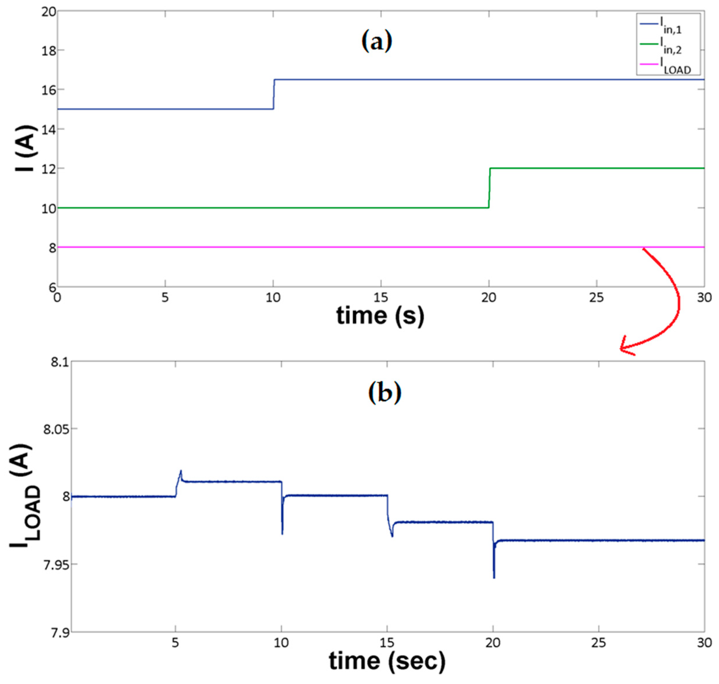
In a similar way, and taking into account the local constant power loads, changes occurred with the source currents around their nominal values , , by varying the coefficients and . As shown in Figure 5, the power injected to the system by Source 1 changed from 80% to 90% of , i.e., became 0.9 from an initial value of 0.8, at t = 10 s, while the supply provided to the system by source 2 changed from 60% to the 80% of , i.e., became 0.8 from an initial value of 0.6, at t = 20 s.
The system parameters were taken from [34,35] and are provided in Table 1, while all of the controllers’ gains are given in Table 2.
It is worth noting that due to the relatively slow response of the droop-based voltage control, and due to the very small values of the droop-coefficients, it was indeed feasible to neglect from the analysis the very small DC voltage deviations, and to effectively substitute the constant power loads with constant current sources. Since this holds true in the whole region of the expected operating conditions, the assumption made for the constant power loads was not yet a “small signal” hypothesis, and did not practically affect the nonlinear nature of the original system. This is fully verified by the results presented, where the constant power load was accurately simulated (not being considered as a current source). As shown in Figure 5a, the current deviations, caused by the different operating conditions of the DC system could not be visible, except only in a very large zoom representation; as indicated in Figure 5b, very small permanent changes that are lower than 0.375% are visible.
Figure 6 represents the SoC of both storage devices (batteries). Meanwhile, it should be noted that the battery SoC calculation was obtained from the following equation:
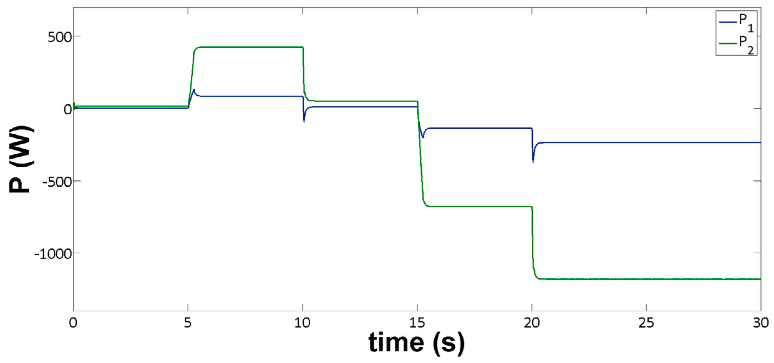
where represents the initial battery value, and is the storage device capacity [24]. Figure 7 depicts the power on each of the battery branches. It is observed that the DC voltage/power droop-based controllers achieved an almost five-to-one power balance between the fast charging and the slow charging branches, as well a five-to-one faster SoC rate at the first branch. The accuracy of the sharing rate is maintained during the entire operation time, while the power is exchanged between the energy storage devices and the DC-microgrid in both directions via the bidirectional converter interfaces.
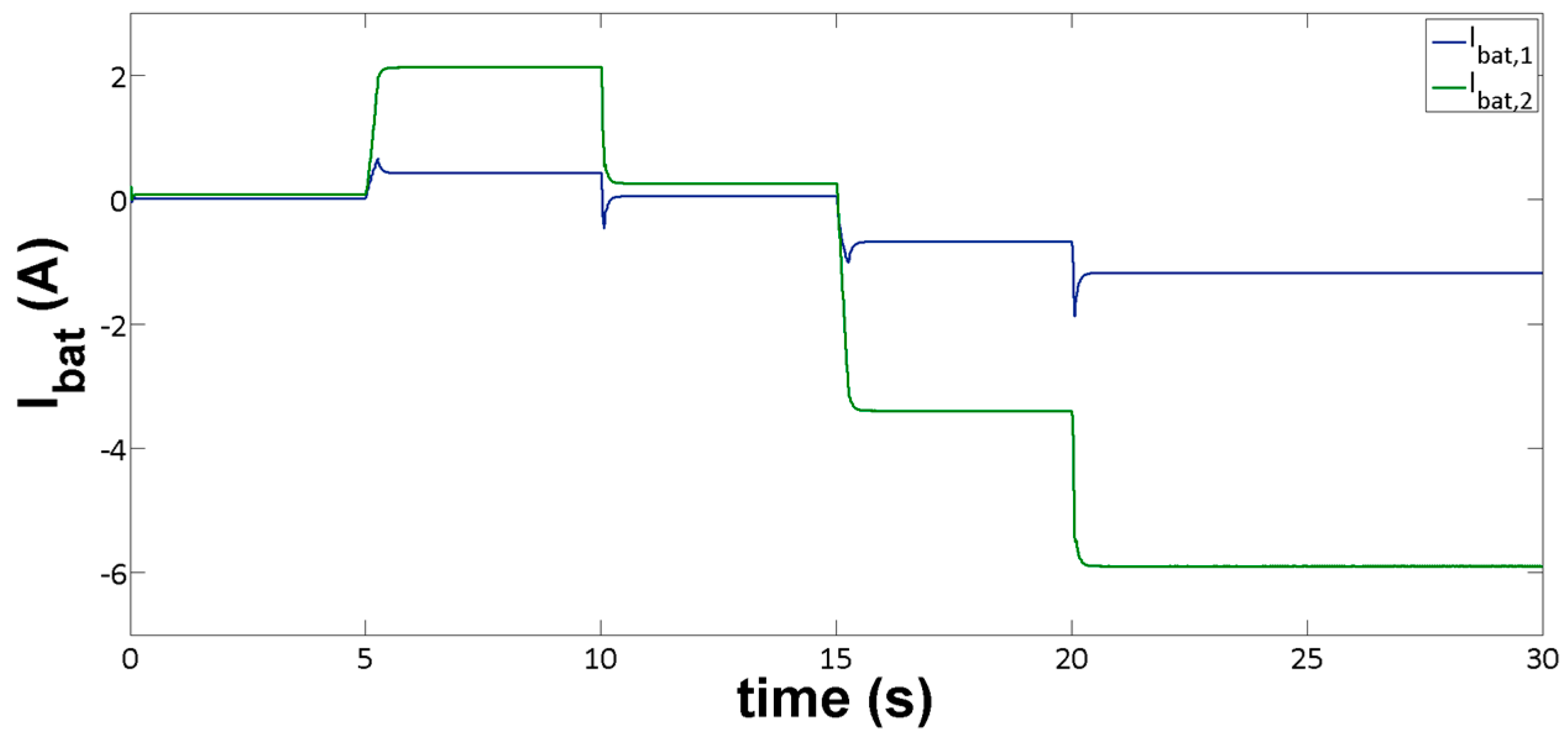
In accordance to Figure 8, the same sharing ratio (five-to-one), occurred as expected. This ratio also occurred between and , which are observed to tend to their steady state values rapidly after the resistive load and the source current changed. Currents and take positive and negative values, representing the charging/discharging process of the two energy storage devices, satisfying the power demands at each time instant, and ensuring that power balance is maintained in the entire DC distribution system. It is noted that the positive current values occurred during the drop of the resistive part of the load, when both battery branches injected power to the system, thus operating as supplementary sources to the DERs.
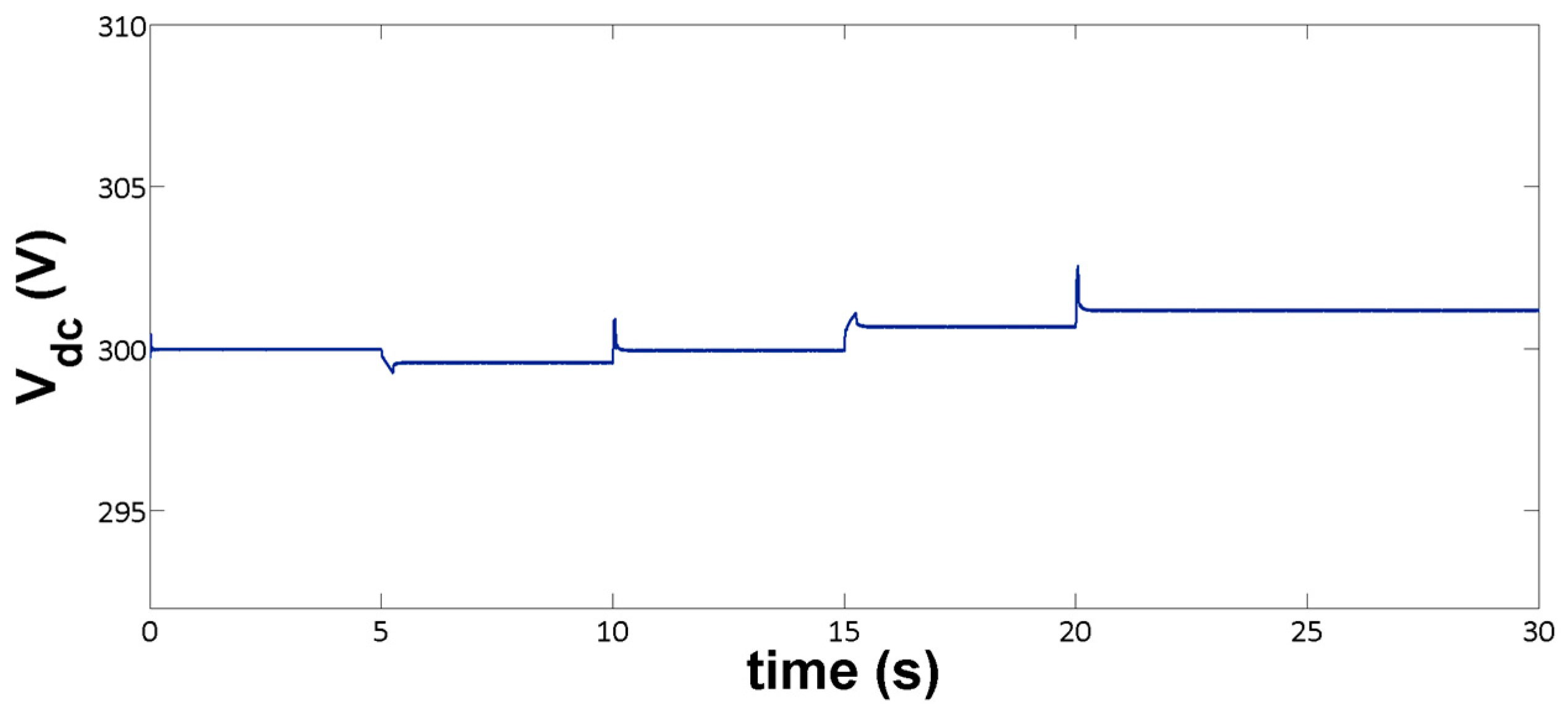
Figure 9 shows that the voltage at the load node quickly reached, after a short transient period, a value very close to its predefined nominal value . The deviation from the steady state value is not significant, while the stable performance and convergence to the equilibrium is verified in accordance with the theoretical analysis. The small observed deviation represents the trade-off between the voltage level and the sharing ratio imposed by the droop coefficients. Indeed, the DC voltage remains very close to 300 V regardless of the operating conditions.
In all cases, a bounded transient behavior was indicated, with limited overshoots and no oscillations. The system was stabilized at the desired equilibrium, as it was generated by the outer-loop PI and droop controllers. The implemented control scheme led the system to the steady state effectively and smoothly, thus verifying the stability analysis.
6. Conclusions
The complete nonlinear model of a particular DC distribution system driven by PI cascaded droop-based controllers familiar to the industrial engineers, was extensively analyzed for its stability, and was further examined by simulations. The whole design had as a main concept, power balance and management to be implemented only via the energy storage devices. A charge sharing scenario between a fast charging and a slow charging battery unit branch was developed. The theoretical analysis indicates that such a scheme can effectively operate on the stable region, while the simulation results confirm a very satisfactory performance under a series of rapid load changes and various injected power situations from the DERs. Both the transient and the steady state responses verify the effectiveness of the method applied, as expected by the theoretical analysis.
Author Contributions
The paper was a collaborative effort between the authors. The authors contributed collectively to the theoretical analysis, modelling, simulation, and manuscript preparation. All authors revised and approved the publication.
Conflicts of Interest
The authors declare no conflict of interest.
Appendix A
Appendix B
Theorem A.1.
Let for the system [31]:
there exists a which is continuously differentiable function, such that:
where and are class k functions, is a class k function, and is a continuous positive definite function on . Then the system is input-to-state stable (ISS).
Consider the nonlinear system:
Assumption A.1.
For the nonlinear system (A1), (A2), it holds that:
- For any trajectory , for all , the matrix is locally Lipchitz and Hurwitz.
- Matrix is constant, i.e., .
- Input is assumed to be constant, i.e., , .
Assumption A.2.
It holds true that:
- System (A1), (A2) is passive with respect to the input and output , for some storage function .
- There exist non-zero equilibrium points for (A1): that are distinct, each satisfying the equation , for some .
- No limit cycles exist in .
Theorem A.2.
The state trajectories of the passive system (A1), (A2), satisfying Assumptions A.1 and A.2, converge to an equilibrium .
References
- Hatziargyriou, N.; Asano, H.; Iravani, R.; Marnay, C. Microgrids. IEEE Power Energy Mag. 2007, 5, 78–94. [Google Scholar] [CrossRef]
- Guerrero, J.M.; Vasquez, J.C.; Matas, J.; Garcia de Vicuna, L.; Castilla, M. Hierarchical control of droop-controlled AC-DC microgrids—A general approach toward standardization. IEEE Trans. Ind. Electron. 2011, 58, 158–172. [Google Scholar] [CrossRef]
- Maknouninejad, A.; Qu, Z.; Lewis, F.L.; Davoudi, A. Optimal, nonlinear, distributed designs of droop controls for DC microgrids. IEEE Trans. Smart Grid 2014, 5, 78–94. [Google Scholar] [CrossRef]
- Elsayed, A.T.; Mohamed, A.A.; Mohamed, O.A. DC microgrids and distribution systems: An overview. Electr. Power Syst. Res. 2015, 119, 407–417. [Google Scholar] [CrossRef]
- Yu, S.-Y.; Kim, H.-J.; Kim, J.-H.; Han, B.M. SoC-based output voltage control for BESS with a lithium-ion battery in a stand-alone DC microgrid. Energies 2016, 9, 924. [Google Scholar] [CrossRef]
- Sokal, N.O. System oscillations from negative input resistance at power input port of switching-mode regulator, amplifier, DC/DC converter, or DC/AC inverter. In Proceedings of the IEEE Power Electronics Specialists Conference (PESC), Pasadena, CA, USA, 11–16 June 1973; pp. 138–140. [Google Scholar]
- Xiaogang, F.; Jinjun, L.; Lee, F.C. Impedance specifications for stable DC distributed power systems. IEEE Trans. Power Electron. 2002, 17, 157–162. [Google Scholar] [CrossRef]
- Yu, X.; Salato, M. An optimal minimum-component DC-DC converter input filter design and its stability analysis. IEEE Trans. Power Electron. 2014, 29, 829–840. [Google Scholar]
- Kahrobaeian, A.; Yasser, A.-R.; Mohamed, I. Analysis and mitigation of low frequency instabilities in autonomous medium-voltage converter-based microgrids with dynamic loads. IEEE Trans. Ind. Electron. 2014, 61, 1643–1658. [Google Scholar] [CrossRef]
- Radwan, A.A.; Mohamed, Y.A. Analysis and active-impedance-based stabilization of voltage-source-rectifier loads in grid-connected and isolated microgrid applications. IEEE Trans. Sustain. Energy 2013, 3, 563–576. [Google Scholar] [CrossRef]
- Lago, J.; Heidwein, M.L. Operation and control oriented modeling of a power converter for current balancing and stability improvement of DC active distribution networks. IEEE Trans. Power Electron. 2011, 26, 877–885. [Google Scholar] [CrossRef]
- Anand, S.; Fernandes, B.G.; Guerrero, J.M. Distributed control to ensure proportional load sharing and improve voltage regulation in low voltage microgrids. IEEE Trans. Power Electron. 2013, 28, 1900–1913. [Google Scholar] [CrossRef]
- Dragicevic, T.; Lu, X.; Vasquez, J.C.; Guerrero, J.M. DC microgrids—Part I: A review of control strategies and stabilization tecnhiques. IEEE Trans. Power. Electr. 2016, 31, 4876–4891. [Google Scholar]
- Peyghami-Akhuleh, S.; Mokahtari, H.; Chiang Lol, P.; Blaaberg, F. Distributed secondary control in DC microgrids with low-bandwidth communication link. In Proceedings of the IEEE Power Electronics, Drive Systems & Technologies Conference (PEDSTC 2016), Tehran, Iran, 14–16 February 2016; pp. 641–645. [Google Scholar]
- Peyghami, S.; Davari, P.; Mokahtari, H.; Chiang Lol, P.; Blaaberg, F. Synchronverter-enabled DC power sharing approach for LVDC microgrids. IEEE Trans. Power Electron. 2016. [Google Scholar] [CrossRef]
- Anand, S.; Fernandes, B.G. Reduced-order model and stability analysis of low-voltage DC microgrid. IEEE Trans. Ind. Electron. 2013, 60, 5040–5049. [Google Scholar] [CrossRef]
- Kwasinski, A.; Krein, P.T. Passivity-based control of buck converters with constant-power loads. In Proceedings of the IEEE Power Electronics Specialists Conference (PESC 2007), Orlando, FL, USA, 17–21 June 2007; pp. 259–265. [Google Scholar]
- Onwuchekwa, C.N.; Kwasinski, A. Analysis of boundary control for buck converters with instantaneous constant-power loads. IEEE Trans. Power. Electr. 2010, 25, 2018–2032. [Google Scholar] [CrossRef]
- Kwasinski, A.; Onwuchekwa, C.N. Dynamic behavior and stabilization of DC microgrids with instantaneous constant-power loads. IEEE Trans. Power. Electr. 2011, 26, 822–834. [Google Scholar] [CrossRef]
- Salomonsson, D.; Sannino, A. Load modelling for steady-state and transient analysis of low-voltage DC systems. IET Electr. Power Appl. 2007, 1, 690–696. [Google Scholar] [CrossRef]
- Rudraraju, S.R.; Srivastava, A.K.; Srivastava, S.C.; Schulz, N.N. Small signal stability analysis of a shipboard MVDC power system. In Proceedings of the IEEE Electric Ship Technologies Symposium (ESTS), Sheraton Inner Harbor, Baltimore, MD, USA, 20–22 April 2009; pp. 135–141. [Google Scholar]
- Griffo, A.; Wang, J. Modeling and stability analysis of hybrid power systems for the more electric aircraft. Electr. Power Syst. Res. 2012, 82, 59–67. [Google Scholar] [CrossRef]
- Aggeler, D.; Canales, F.; Zelaya, H.; La Parra, D.; Coccia, A.; Butcher, N.; Apeldoorn, O. Ultra-fast DC-charge infrastructures for EV-mobility and future smart grids. In Proceedings of the Innovative Smart Grid Technologies Conference Europe (ISGT Europe), IEEE PES, Chalmers Lindholmen, Gothenburg, Sweden, 10–13 October 2010; pp. 1–8. [Google Scholar]
- Lu, X.; Sun, K.; Guerrero, J.M.; Vasquez, J.C.; Huang, L. State-of-charge balance using adaptive droop control for distributed energy storage systems in DC microgrid applications. IEEE Trans. Power. Electr. 2014, 61, 2804–2815. [Google Scholar] [CrossRef]
- Li, C.; Dragicevic, T.; Diaz, N.L.; Vasquez, J.C.; Guerrero, J.M. Voltage scheduling droop control for State-of-charge balance of distributed energy storage in DC microgrids. In Proceedings of the IEEE Inernational Energy Conference (EnergyCon’14), Zagreb, Croatia, 13–16 May 2014; pp. 1310–1314. [Google Scholar]
- Tucci, M.; Riverso, S.; Vasquez, J.C.; Guerrero, J.M.; Ferrari-Trecate, G. Voltage control of DC islanded microgrids: A decentralized scalable approach. In Proceedings of the 54th Conference on Decision and Control and European Control Conference (CDC-ECC), Osaka, Japan, 15–18 December 2015; pp. 3149–3154. [Google Scholar]
- Sontag, E.D. Input to State Stability: Basic Concepts and Results. Nonlinear and Optimal Control Theory; Springer Press: New York, NY, USA, 2008; pp. 163–220. [Google Scholar]
- Sontag, E.D.; Wang, Y. On the characterizations of the input-to-state stability property. Syst. Control Lett. 1995, 24, 351–359. [Google Scholar] [CrossRef]
- Hu, Y.; Yurkovich, S.; Guezennec, Y.; Bornatico, R. Model-based calibration for battery characterization in HEV applications. In Proceedings of the American Control Conference (ACC), Seattle, WA, USA, 11–13 June 2008; pp. 318–325. [Google Scholar]
- Yasdani, A.; Iravani, R. Voltage-Sourced Converters in Power Systems; IEEE/Wiley: Hoboken, NJ, USA, 2010. [Google Scholar]
- Khalil, H.K. Nonlinear Systems, 3rd ed.; Prentice-Hall: Upper Saddle River, NJ, USA, 2002. [Google Scholar]
- Konstantopoulos, G.C.; Alexandridis, A.T. Stability and convergence analysis for a class of nonlinear passive systems. In Proceedings of the 50th Conference on Decision and Control and European Control Conference (CDC-ECC), Orlando, FL, USA, 12–15 December 2011; pp. 1753–1758. [Google Scholar]
- Konstantopoulos, G.C.; Alexandridis, A.T. Generalized nonlinear stabilizing controllers for hamiltonian passive systems with switching devices. IEEE Trans. Control Syst. Technol. 2013, 21, 1479–1488. [Google Scholar] [CrossRef]
- Makrygiorgou, J.J.; Alexandridis, A.T. Dynamic analysis of induction machine driven electric vehicles based on the nonlinear accurate model. In Proceedings of the 24th Mediterranean Conference on Control and Automation (MED), Athens, Greece, 21–24 June 2016; pp. 479–484. [Google Scholar]
- Chen, M.; Rincοn-Mora, G.A. Accurate electrical battery model capable of predicting runtime and I-V performance. IEEE Trans. Energy Convers. 2006, 21, 504–511. [Google Scholar] [CrossRef]
Figure 1.
The entire DC distribution system.

Figure 2.
The battery/bidirectional DC/DC boost converter branch model.
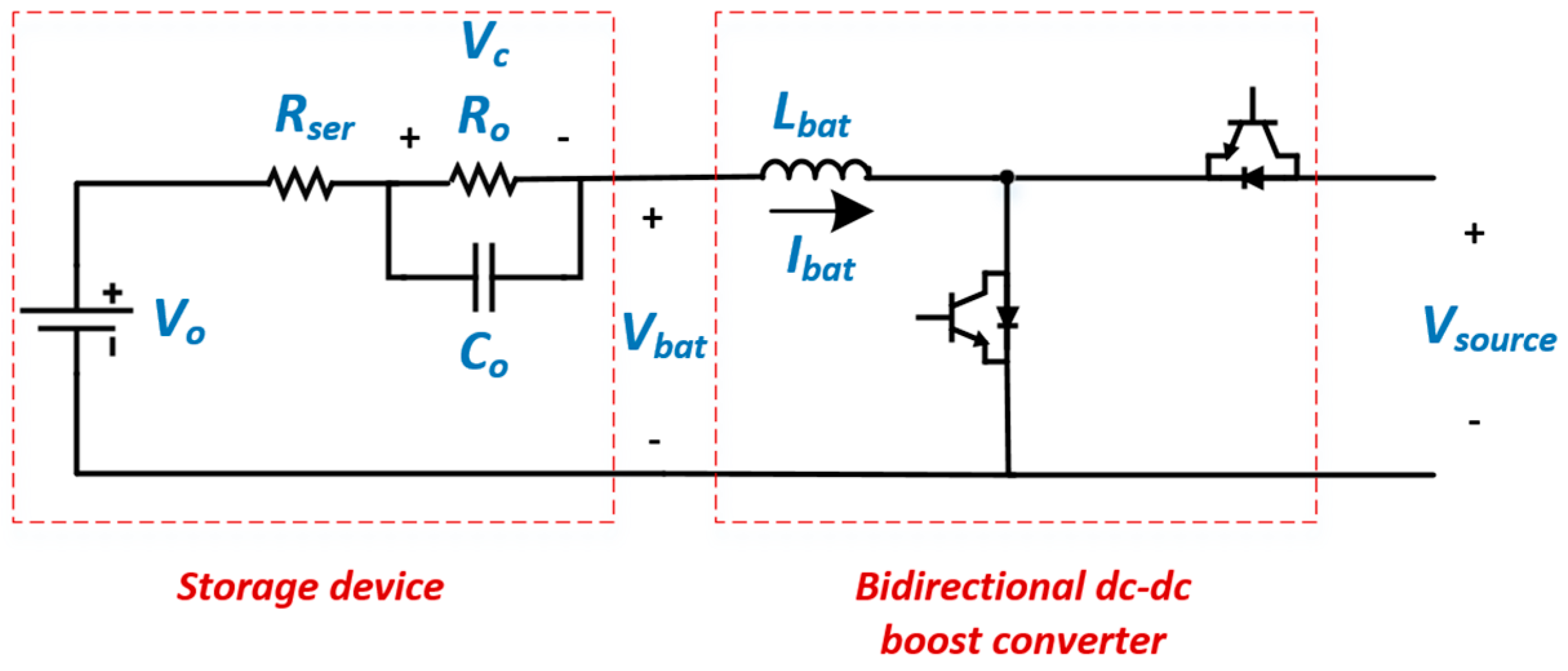
Figure 3.
The proposed droop-based cascaded control scheme.

Figure 4.
Change of the resistive part of the load.

Figure 5.
(a) The net input supply at each distributed energy resource (DER) bus and the current at the constant power load bus; (b) Details of the current changes of the constant power load at the load bus (zoomed).
Figure 5.
(a) The net input supply at each distributed energy resource (DER) bus and the current at the constant power load bus; (b) Details of the current changes of the constant power load at the load bus (zoomed).

Figure 6.
State of charge (SoC) of each battery branch.

Figure 7.
Power on each battery branch.

Figure 8.
Current on each battery branch.

Figure 9.
DC voltage at the load node.

Table 1.
System Parameters.
| Parameters | Value |
|---|---|
| 100 mH | |
| 0.0745 Ω | |
| 4475 F | |
| 0.0489 Ω | |
| 200 V | |
| 120 Ω | |
| 1.1 mF | |
| 1.1 mF | |
| 0.4 mH | |
| 0.15 Ω | |
| 3060 F |
Table 2.
Controllers’ Gains.
| Gain | Value |
|---|---|
| 10 | |
| 0.1 | |
| 0.5 | |
| 25 | |
| 0.005 | |
| 0.001 | |
| 0.01 |
© 2017 by the authors. Licensee MDPI, Basel, Switzerland. This article is an open access article distributed under the terms and conditions of the Creative Commons Attribution (CC BY) license (http://creativecommons.org/licenses/by/4.0/).
Share and Cite
MDPI and ACS Style
Makrygiorgou, D.I.; Alexandridis, A.T. Stability Analysis of DC Distribution Systems with Droop-Based Charge Sharing on Energy Storage Devices. Energies 2017, 10, 433. https://doi.org/10.3390/en10040433
AMA Style
Makrygiorgou DI, Alexandridis AT. Stability Analysis of DC Distribution Systems with Droop-Based Charge Sharing on Energy Storage Devices. Energies. 2017; 10(4):433. https://doi.org/10.3390/en10040433
Chicago/Turabian StyleMakrygiorgou, Despoina I., and Antonio T. Alexandridis. 2017. "Stability Analysis of DC Distribution Systems with Droop-Based Charge Sharing on Energy Storage Devices" Energies 10, no. 4: 433. https://doi.org/10.3390/en10040433
Note that from the first issue of 2016, this journal uses article numbers instead of page numbers. See further details here.