Article

Potential of Utilizing Different Natural Cooling Sources to Reduce the Building Cooling Load and Cooling Energy Consumption: A Case Study in Urumqi

Department of Building Science, Beijing Key Laboratory of Indoor Air Quality Evaluation and Control, Tsinghua University, Beijing 100084, China
*
Author to whom correspondence should be addressed.
Energies 2017, 10(3), 366; https://doi.org/10.3390/en10030366
Submission received: 5 January 2017 / Revised: 18 February 2017 / Accepted: 9 March 2017 / Published: 15 March 2017

Abstract

:
Generally, Central Asia is typical for regions with strong solar radiation and various natural cooling sources. The heat gain from the building envelope accounts for a large part of the cooling load there. Thus, the pipe-embedded envelope is receiving attention as a semi-active system of utilizing natural energy for cooling. In this study, the performance of the pipe-embedded envelope used in Urumqi is numerically investigated. The energy saving potential regarding evaporative cooling and a ground-source heat exchanger (GSHE) is evaluated over a complete summer. The results show that the built-in pipes can reduce 80% of the solar heat gain through windows, with an effectiveness of around 60%. External windows rather than internal windows should be insulated because the air cavity is cool. With respect to the pipe-embedded wall, it becomes a radiant cooling panel absorbing the heat from the room, with an effectiveness around 83%. The seasonal cooling energy is decreased by 25%–50% in a typical office with a pipe-embedded envelope. Offices with a large window-to-wall ratio are acceptable because natural cooling is employed. GSHE performs the best among the selected sources. The effectiveness of evaporative cooling is also satisfactory, with an energy saving rate of 27%. Overall, the pipe-embedded system is suitable for climatic regions like Urumqi.

1. Introduction

The Silk Road was an ancient network through regions of the Asian continent connecting China to the Mediterranean Sea. Generally, Central Asia is one of the most important components of the Silk Road. The climate of this region has a distinct feature. In the daytime during summer, the solar radiation is strong and the air temperature is high. Thus, the energy consumption of traditional air-conditioning in office buildings here is very high. The cost of dehumidification is low due to the dry climate. The sensible heat transferred through the building envelope accounts for a significant proportion of the total cooling load. It is energy-efficient to reduce the cooling load in this region, especially the load gain from the building envelope.
The building envelope comprises of the walls, windows, and roof. Conventionally, thermal insulation is applied to the walls to enhance the thermal resistance [1]. Ojanen et al. [2] reviewed the current situation of building thermal insulation. With decades of development, thermal insulation became one of the most efficient approaches for reducing the heat transfer through the wall. However, large thermal resistance may also influence the heat dissipation of the wall when the ambient environment is cool [3]. For example, the air temperature during summer nights and transition seasons is low in the Central Asian region. Intensive insulation will reduce the heat dissipation effect and, consequently, most indoor heat gain has to be handled by air-conditioning. In addition, thermal insulation faces the limitations of thickness [4], renovation [5], and fire safety [6]. Thus, it is wise to find other alternative solutions together with thermal insulation.
With respect to windows, numerous studies have been conducted to improve their insulation and shading performance. Glazing technologies, such as gas-filled glazing [7], multilayer glazing and vacuum glazing [8], have significantly promoted the thermal insulation of windows. Manz et al. [9] even developed a window with a heat transfer coefficient of 0.2 W/(m2∙K). Coating technologies, such as low emissivity (low-e) coatings [10], have minimized the incident solar radiation to the indoor space. However, the cost of high-performance coating is very expensive. Intensive shading will also have a poor influence for heating in winter. Double skin façade (DSF) is a type of advanced window system. The venetian blinds of DSF can block solar radiation and the air cavity between the two façades can enhance the thermal resistance. Hong et al. [11] investigated the seasonal energy efficiency strategies of a DSF used in Korea. The largest reduction rate of cooling energy consumption in that case was 13%. Cetiner and Özkan [12] assessed the performance of a DSF used in Istanbul. The energy saving rate in that case was 23%. Chan et al. [13] evaluated the technique-economic efficiency of a DSF used in Hong Kong, the cooling load was reduced by 26%. Though DSFs have shown the potential for energy savings, the heat gain through DSFs is still considerable [14]. Parra et al. [15] demonstrated that the venetian blinds have a notable effect on thermal performance of the DSF, and the temperature of venetian blinds could be higher than 50 °C under exposure to solar radiation [16]. Gratia and De Herde [17] indicated that DSFs might cause overheating and a greenhouse effect in the air cavity. Especially under the severe summer climate in the Central Asian region, the traditional DSFs are not adequate for significantly reducing the cooling energy consumption.
Except for the mentioned passive technologies, embedding pipes into the building envelope and utilizing natural energy to cool the windows and walls, has been proven very promising. Xu et al. [18] presented the concept of the pipe-embedded wall and reviewed its practical applications. The results showed that the active building envelope has the potential for energy conservation. Shen and Li [19] investigated the dynamic thermal performance of a pipe-embedded wall utilizing evaporative cooling water. It indicated that the reduction rate of electricity consumption for cooling could be higher than 50%. A ground-source heat exchanger (GSHE) also could be used as the cooling source of a pipe-embedded wall [20]. With regard to the pipe-embedded window, its average solar energy transmittance is only 13% and its window temperature is decreased by 10 °C under typical summer conditions [14,21]. Overall, the effectiveness of the pipe-embedded envelope is high because of the direct use of natural cooling sources which does not consume extra electricity.
Generally speaking, the Central Asian region has various natural cooling sources. The evaporative cooling there is efficient, and the temperature of ground soil is low. Thus, it may be suitable to adopt the pipe-embedded envelope and utilize natural energy in these regions. However, the investigation of the pipe-embedded envelope applied to these regions is inadequate. In addition, the current studies on the pipe-embedded envelope are separated to either windows or walls, respectively, and only the envelope is considered rather than the entire room. The comparison of the performance among different natural cooling sources is also lacking.
Thus, a typical office with a synthetic pipe-embedded envelope utilizing natural cooling is presented in this study. Urumqi (latitude and longitude: 43°49′ N, 87°36′ E) is employed in the investigation as it is one of the largest cities in the Central Asian region. The hourly heat transfer of the novel envelope is numerically investigated over a complete summer. The effects of window, wall, and indoor heat sources are all taken into account. The energy saving performance of three natural cooling sources are considered: direct evaporative cooling (DEC), indirect evaporative cooling (IEC), and GSHE.

2. Methodology

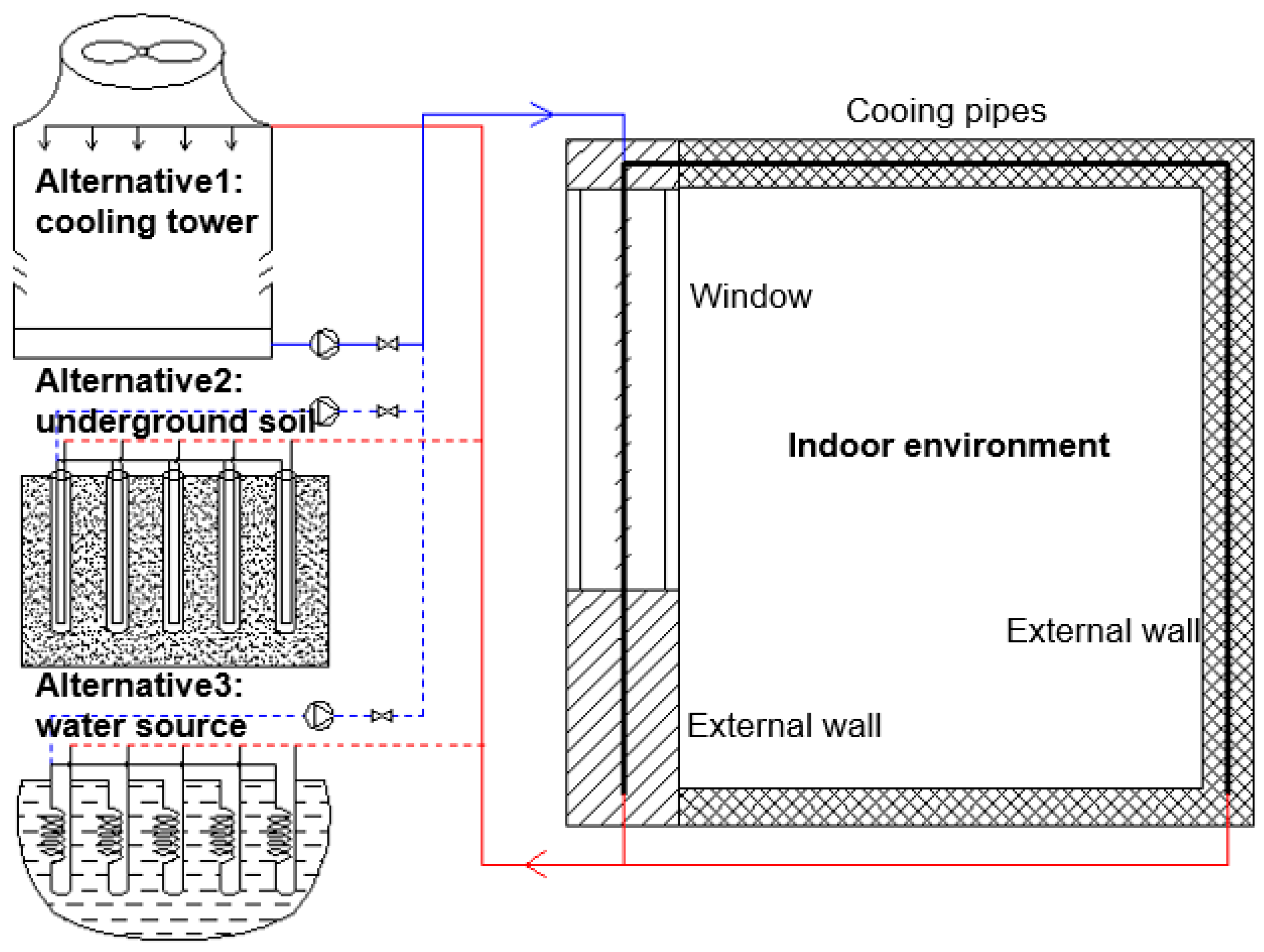
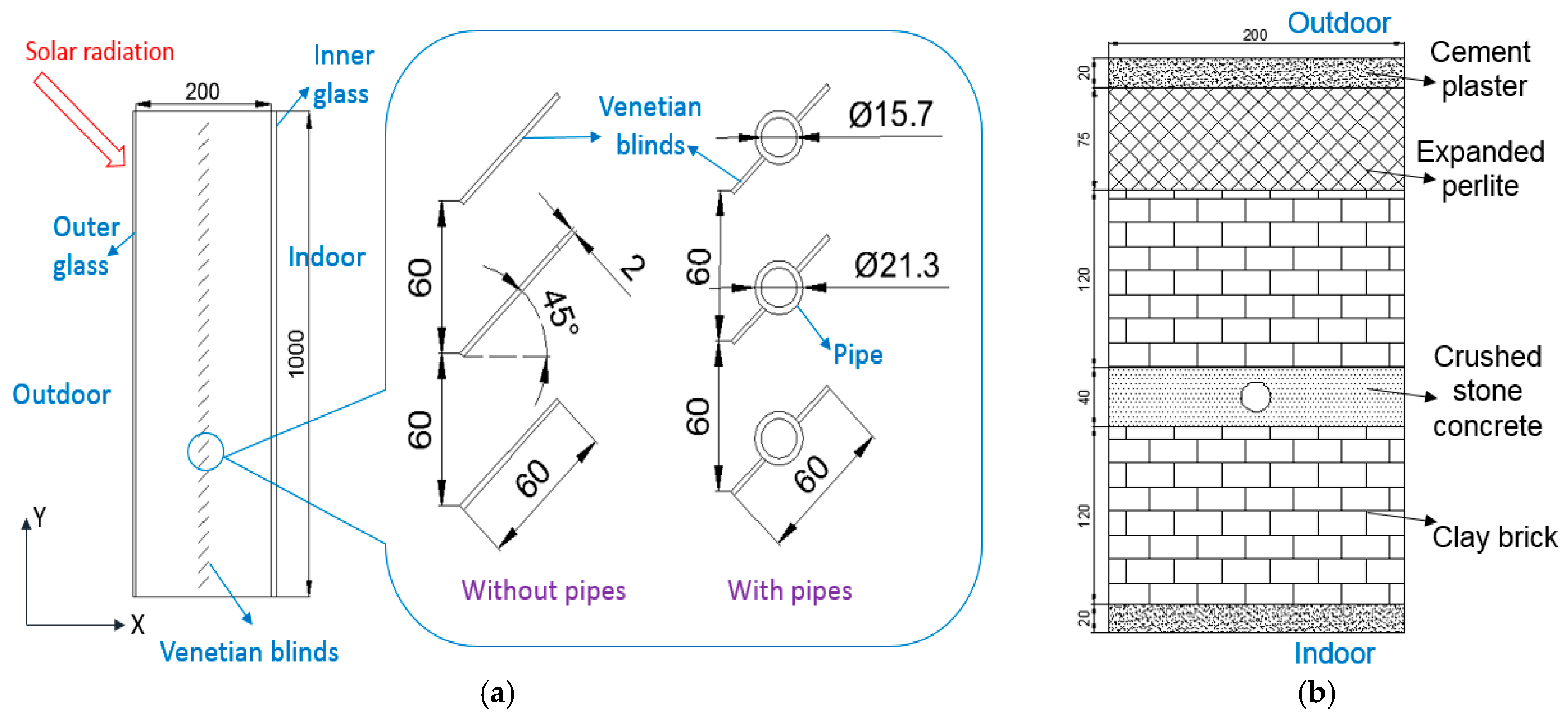
2.1. Description of the Synthetic Pipe-Embedded Envelope
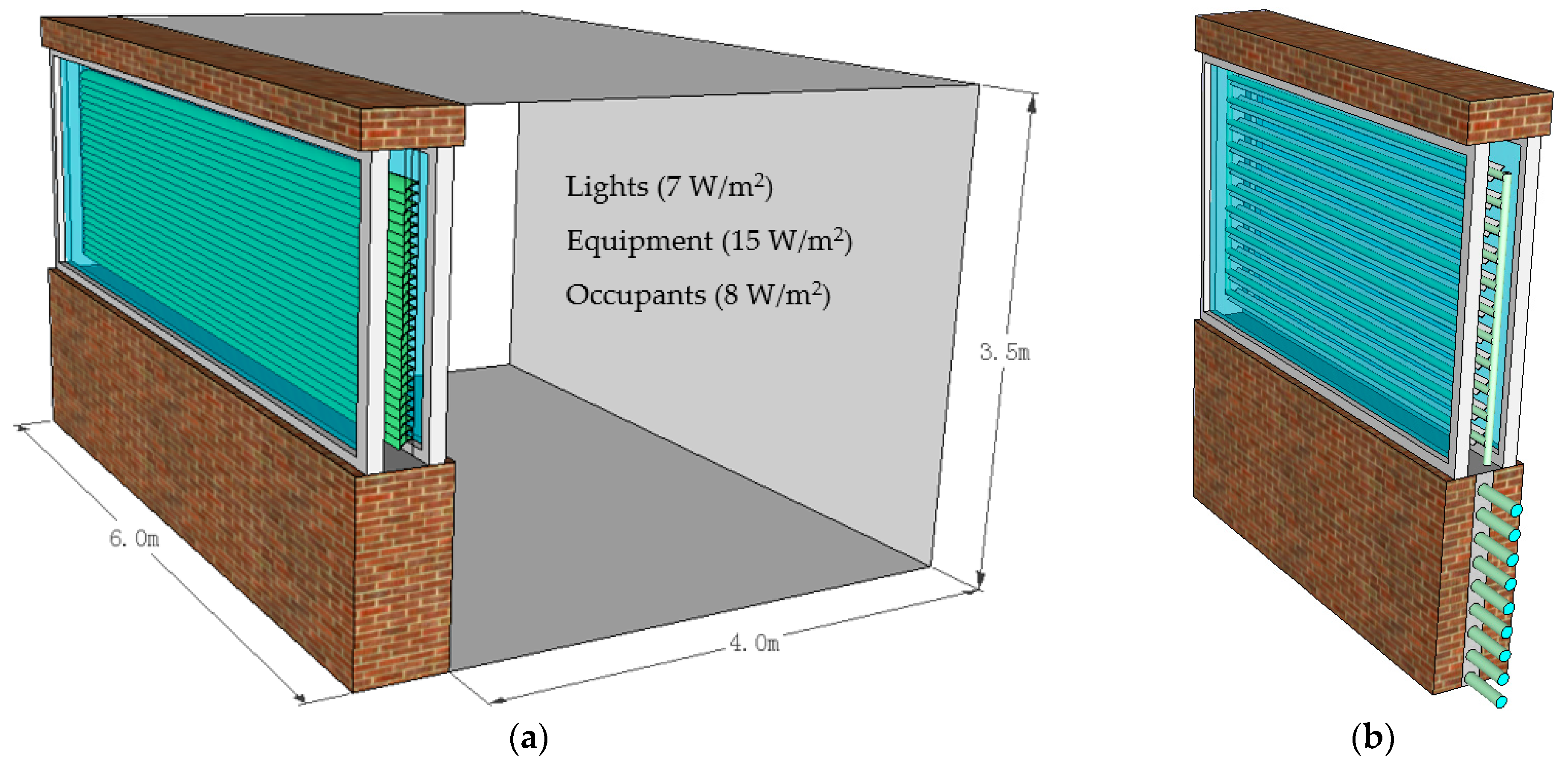
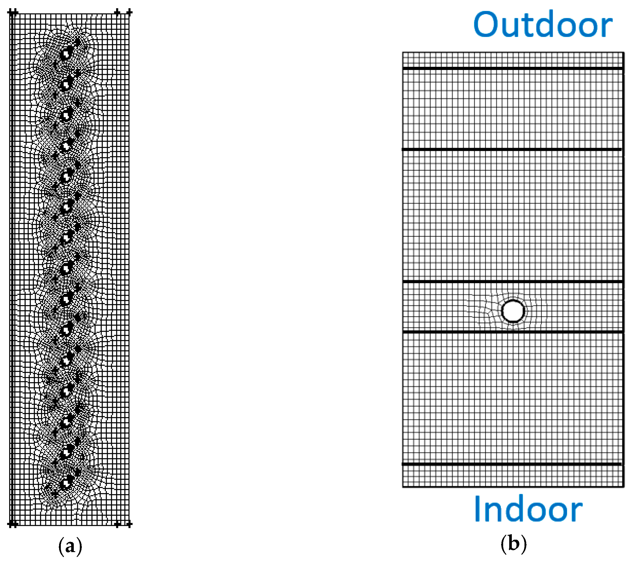
The schematic diagram of the pipe-embedded envelope is shown in Figure 1. Cooling pipes are embedded into the wall and the double pane window. Cooling water flows inside to take away the heat from the envelope. The heat transfer of the pipe-embedded structure is more efficient than the traditional indoor fan coil unit. Firstly, the heat transfer area of the pipe-embedded system is sufficient because the whole envelope can be considered as a heat exchanger. Secondly, the heat transfer coefficient of the pipe-embedded system is high. In the wall, the pipes directly contact the solid surface. In the window, the pipes directly absorb the incident solar radiation. Finally, natural energy sources can be employed directly for cooling regarding the high temperature of the window and wall. According to the climatic feature of Urumqi, DEC, IEC, and GSHE are applied as the natural cooling sources in this study.

2.2. Physical Model

A typical office is adopted to evaluate the performance of the synthetic pipe-embedded envelope, as shown in Figure 2. The dimensions of the office are 6.0 m (length) × 4.0 m (width) × 3.5 m (height). The external envelope of the office consists of window and wall. Window-to-wall ratio (WWR) varies in different cases. The heat gain from envelope is simulated using a computational fluid dynamics (CFD) program. The indoor heat gain consists of lights (7 W/m2), equipment (15 W/m2), and occupants (8 W/m2) [22]. The working schedule of the office is from 08:00 to 18:00. All of the other settings are the same in the office with traditional and pipe-embedded envelopes except for the pipes.
The heat transfers of the window unit and wall unit are numerically simulated, respectively. As illustrated in Figure 3, a typical double pane window with venetian blinds and a typical wall with bricks and an insulation layer are employed in the study. Cooling pipes are built in the venetian blinds of the window and the interlayer of the wall. The materials in the window are selected based on [23,24]. The glass has different characteristics in long-wave and short-wave bands. The materials in the wall are selected based on [25,26]. The expanded perlite is employed as the insulation material. The detailed information of the materials in the window and wall is listed in Table 1 and Table 2. The insulations of the window and wall are selected complying with the thermal insulation standard in Urumqi [22].

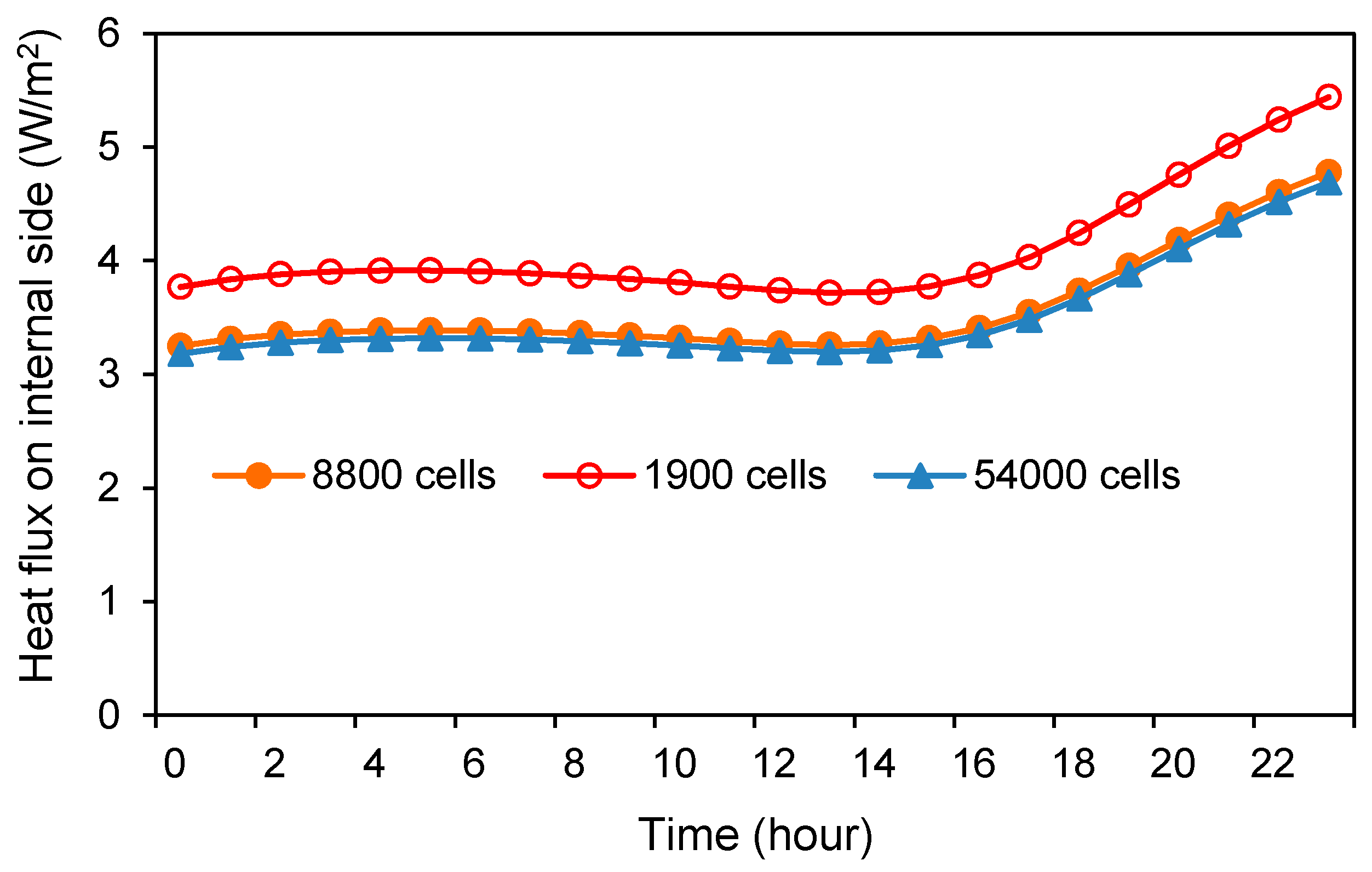
2.3. Numerical Method and Validation

A comprehensive numerical model is built to simulate the heat transfer process through the envelope illustrated in Figure 3. A two-dimensional simplification is adopted in the calculation, corresponding to similar studies [16,23,27]. The simulation is unsteady, and the time step is one hour in each case. There are a total of 1728 time steps. To consider the effect of thermal inertia, the simulation is conducted 10 days before the beginning of the summer period. The computation domain consists of a solid field and fluid field. Navier–Stokes equations are employed for the fluid domain. A partial differential equation of heat conduction is applied for the solid zone. Enhanced wall function is employed for the boundary layer between solid and fluid.
Structured quadratic cells are generated in the main domain except for a part near the round pipes and venetian blinds. The mesh independence for the wall has been checked by developing 54,000, 8800, and 1900 cells. The heat transfer through the wall in a day is simulated, and the comparison of heat flux on the internal surface of wall is illustrated in Figure 4. This indicates that the results from 54,000 to 8800 cells are very close, while the results from coarse cells have a relative error larger than 10%. Thus, the mid-density mesh is employed, whose edge length of the cells is 6 mm, approximately. Similarly, the mesh independence for the window has been checked by developing 300,000, 140,000 and 60,000 cells, and the mesh with 140,000 cells is eventually employed, whose cell edge is about 10 mm. The configuration of the adopted mesh is shown in Figure 5.
All of the equations are solved using the commercial CFD software ANSYS Fluent (Version 14.5, ANSYS Inc., Canonsburg, PA, USA). The turbulence effect is computed by the κ-ε model. Velocity and pressure values are coupled by the SIMPLE scheme. Pressure is discretized by the body-force weighted algorithm. Radiation is calculated by the discrete ordinate (DO) model. The validation of the numerical model and the details of mathematical model are included in our previous studies [14,19,21,28].
In this investigation, both the indoor and outdoor sides of an envelope are set as the boundary condition of the third type. The convective heat transfer coefficients of the surfaces of the envelope are 18 W/(m2∙K) (outdoor side) and 6 W/(m2∙K) (room side). The indoor temperature is fixed to 26 °C. The ambient temperature and solar radiation are determined by referring to the climatic database [29]. The angle of the incident solar ray also changes with time. The velocity of water is 0.5 m/s. The temperature of the water is related to the employed natural cooling source. In the system with DEC and IEC, water temperatures are equal to the wet-bulb and dew point temperature of the outdoor air plus 4 °C. The additional 4 °C is given as a temperature difference for heat exchange to consider the performance of DEC [30] and IEC [31]. In GSHE, water temperature is set as the soil temperature plus 4 °C. The surface soil temperature is 6.6 °C and almost constant throughout the whole year [32]. The cooling season of Urumqi is from 21 June to 31 August.

2.4. Evaluation Index

The heat flux transferred into the room per square meter of envelope can be obtained directly from the CFD simulation. Based on this, the total indoor cooling load Q (W) of the office can be calculated as:
Q = qwallAwall + qwindowAwindow + qindoorAindoor + qfresh
where qwall is the heat gain through the wall, W/m2; qwindow is the heat gain through the window, W/m2; qindoor is the heat gain from the indoor space, 30 W/m2; Awall is the area of the wall, m2; Awindow is the area of the window, m2; Aindoor is the floor area of the office, 24 m2; qfresh is the heat gain from the fresh air, W. Awall and Awindow vary with the WWR in different cases. The amount of fresh air is 90 m3/h for the office [22].
The cooling electricity consumption for the office with the traditional envelope Etrad (W) is calculated as:
Etrad = Qtrad/EERhp
where EERhp is the energy efficiency ratio of a typical cooling system, which is around 4.0 [33]; Qtrad (W) is the indoor cooling load for the traditional office.
The cooling electricity consumption for the office with the pipe-embedded envelope Epipe (W) consists of indoor side, envelope side, and the natural cooling source. Epipe is defined as:
Epipe = Qpipe/EERhp + Qwater/WTFpipe + Esource
where Qpipe is the indoor cooling load for the office with pipes, W; Qwater is the heat flux of the water pipes, which is obtained from CFD simulation, W; WTFpipe is the water transport factor of the water pipes (ratio of transferred heat quantity to the electricity consumption of the pump) [34]; (Qwater/WTFpipe) represents the electricity consumption of transporting the water through the envelope; Esource is the electricity consumption of the natural cooling source. For DEC and IEC, Esource is the electricity consumption of the evaporative cooling machine, which is calculated by:
Esource = Qwater/EERsource
where EERsource is the energy efficiency ratio of the evaporative cooling machine [34,35].
For GSHE, Esource is the electricity consumption of the GSHE pump, which is calculated by:
E s o u r c e = ρ g L V 3600 η
where ρ is the density of water, kg/m3; g is the acceleration of gravity, 9.8 m/s2; η is the pump efficiency; L is the pump lift, m; and V is the flow rate of circulating water, m3/h, which is calculated according to Qwater:
V = 3600 Q w a t e r c ρ Δ t
where ρ is the density of water, kg/m3; c is the specific heat of water, J/(kg·K); and Δt is the temperature difference between the outlet and inlet of GSHE, 3.5 °C.
The electricity reduction rate of the pipe-embedded envelope (ε) is defined by:
ε = E t r a d E p i p e E t r a d
The effectiveness of pipes (η) is defined by:
η = Q t r a d Q p i p e Q w a t e r
where η represents how much cooling energy of the pipes is used on the room side. The cooling source with pipes almost does not consume extra energy if η is close to 100%. Since the cooling tower connected with the traditional air-conditioning also consumes energy, only the increased heat flux on the external surface of the pipe-embedded envelope needs the extra energy consumption of the cooling tower.

3. Results and Discussion

The temperature distribution of the pipe-embedded envelope under typical conditions is illustrated first. Then, the hourly heat transfer process of the envelope in a complete cooling season is investigated regarding the diverse cooling sources in Urumqi. Finally, the accumulated electricity consumption of a typical office is evaluated with different orientations and WWRs.

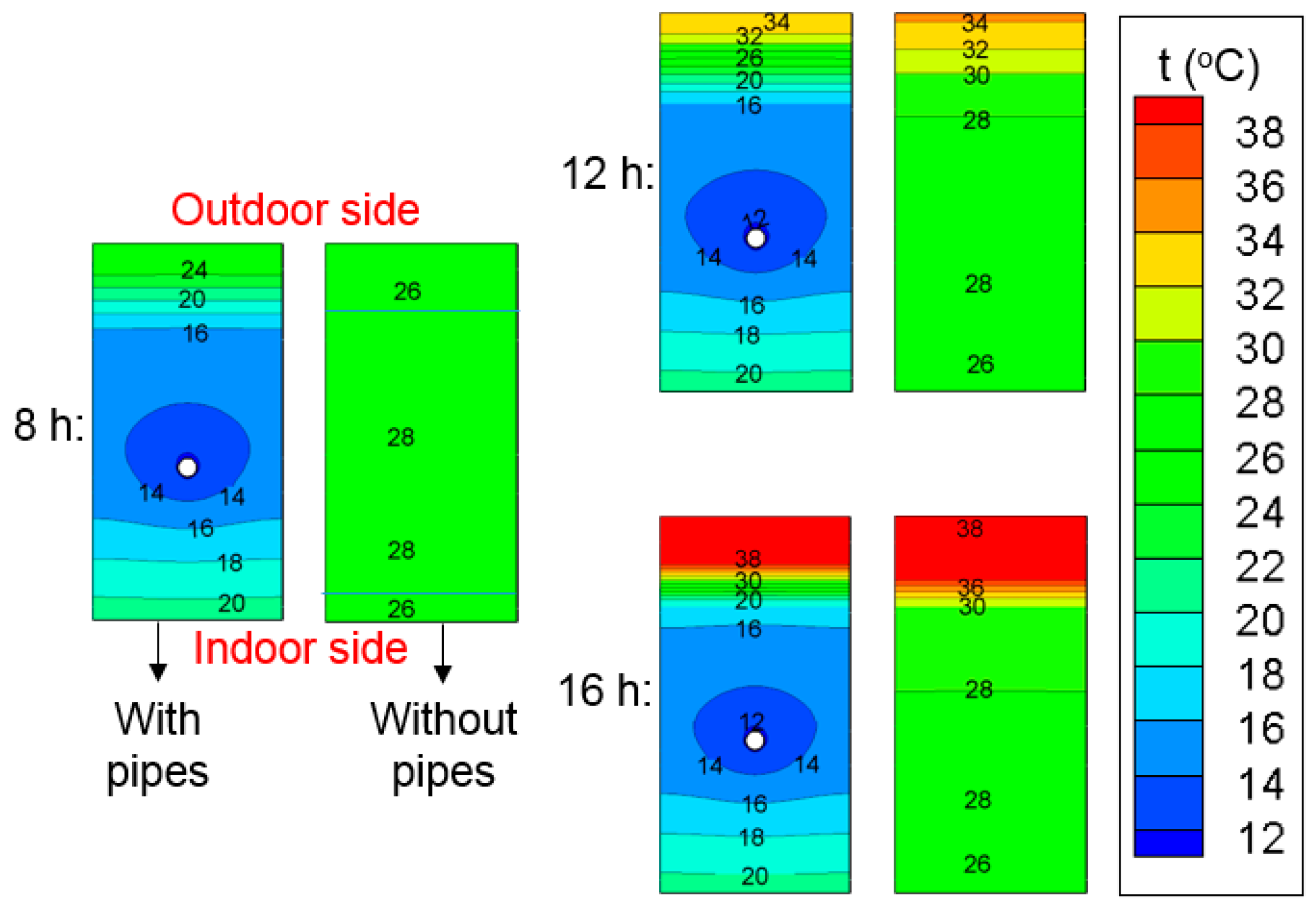
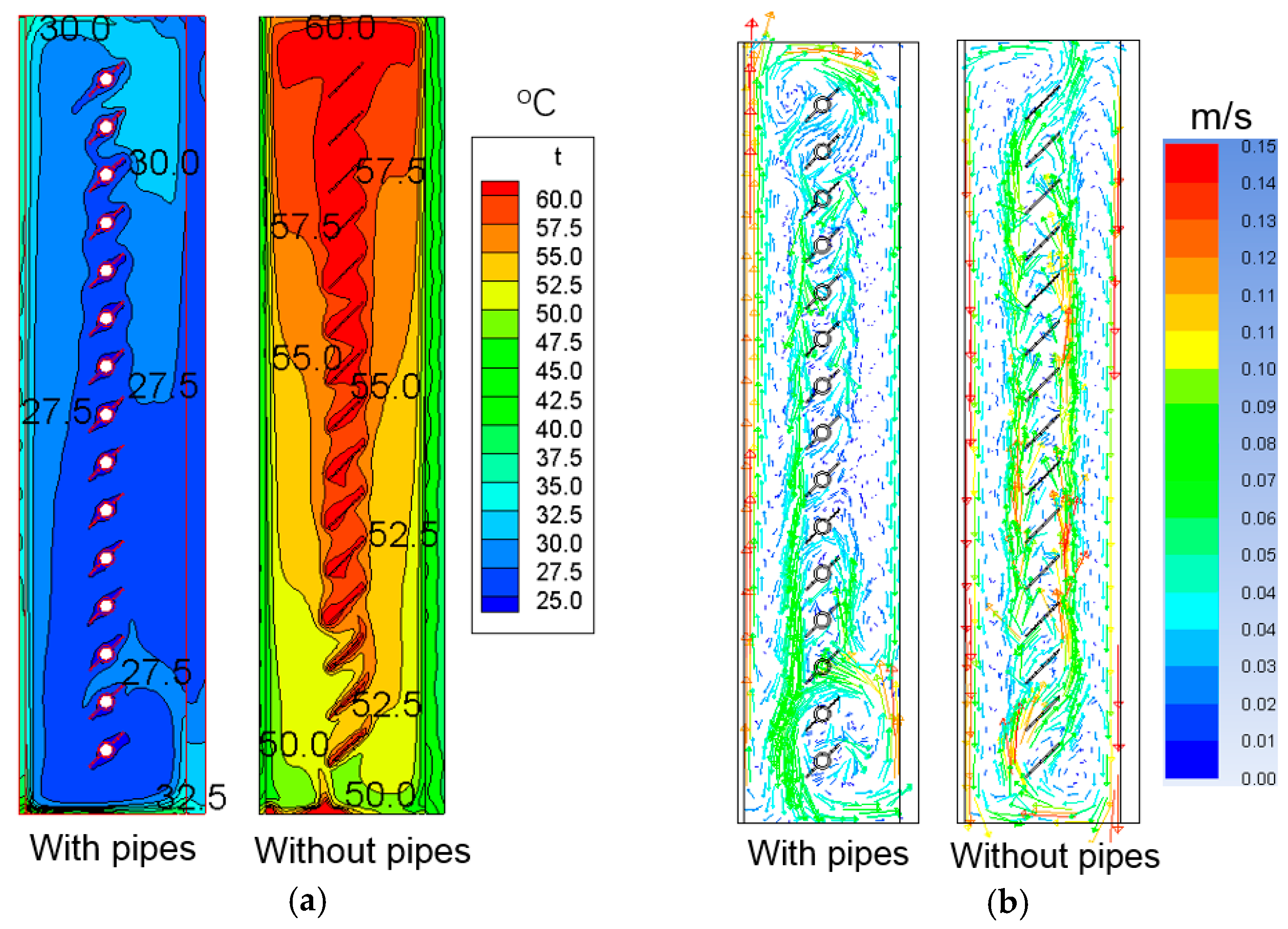
3.1. Temperature Distribution in the Envelope

According to the summer design parameters in Urumqi [29], a typical weather condition is selected to investigate the performance of the cooling pipes. The outdoor temperature is 33 °C, the water temperature is 24.5 °C, and the solar radiation on the external glass is 600 W/m2. The temperature and velocity fields of windows with or without pipes are shown in Figure 6. In the traditional double window without pipes, the blinds are significantly heated because of the strong solar radiation. Thermal stratification occurs in the cavity of the double window, the highest temperature of the air in the top area is even more than 50 °C. The temperature of the blinds is as high as 60 °C, which is corresponding to the experimental results in [16], and a part of the bottom is also hot due to the slant solar radiation. Thus, although the direct heat gain caused by the short-wave solar radiation is reduced, the heat conduction of the internal glass and the long-wave solar radiation from the shading device are still considerable. According to the simulation, 37.3% of the solar energy will transfer into the room. However, with the cooling effect of the embedded pipes, the overall temperature of the novel double window is greatly decreased. The highest air temperature is less than 30 °C. The temperature of blinds is only about 26 °C, and the blinds no longer transfer heat to the indoor space. The neighbor of the shading device even becomes a cool region. In this condition, 60.1% of the heat gain from solar radiation is directly taken away by the cooling pipes, and only 12.2% of the incident radiation transfers into the room eventually. Nevertheless, the heat dissipation to the ambient environment in the pipe-embedded double window is less than that of the traditional double window because the temperature of the pipe-embedded double window is much lower. Thus, the cooling pipes need to deal with more heat. However, its energy-saving potential may still be promising considering the production of cooling water is very efficient compared with the chiller.
The velocity profile in Figure 6b indicates that the overall thermal convection in the traditional window is strong due to its large temperature difference throughout the cavity. The air is heated up by the bottom surface and venetian blinds, and rises alongside the blinds. Then the air falls along the glass as it is cooled down by the glass. The thermal convection is intense especially near the glass. In the pipe-embedded window, the buoyancy-driven flow rises in the region near the external glass because it is heated up by the glass. The thermal convection near the venetian blinds and internal glass is weak due to the small temperature difference. Thus, the heat conduction through the internal glass is reduced in this condition.
A typical day in Urumqi is selected to analyze the effectiveness of the embedded pipes in detail. The boundary conditions are selected from the summer design day in [29]. Dynamic heat transfer is considered due to the thermal inertia of the wall. It is a sunny day and the highest horizontal solar radiation is nearly 800 W/m2. The highest air temperature is 35.4 °C, which occurs at 15:00. Cooling water is produced from DEC. The wet-bulb temperature varies between 15 °C and 20 °C, which is suitable for DEC.
The temperature field in the envelope at different times during the conditions with or without pipes is illustrated in Figure 7. In the traditional wall without pipes, the temperature of the external surface is heated up from noon to night. Especially around 16:00, the highest temperature of the envelope is over 38 °C. The temperature of the internal surface is always more than 26 °C. With the embedded cooling pipes, the temperature of the envelope is significantly reduced. As shown in Figure 7, the heat transferred to the room is effectively reduced by the pipes, and the temperature of the internal surface is about 20 °C, which is even much lower than the room temperature. Thus, the cooling pipes not only decrease the external heat gain through the wall but also absorb the internal heat.

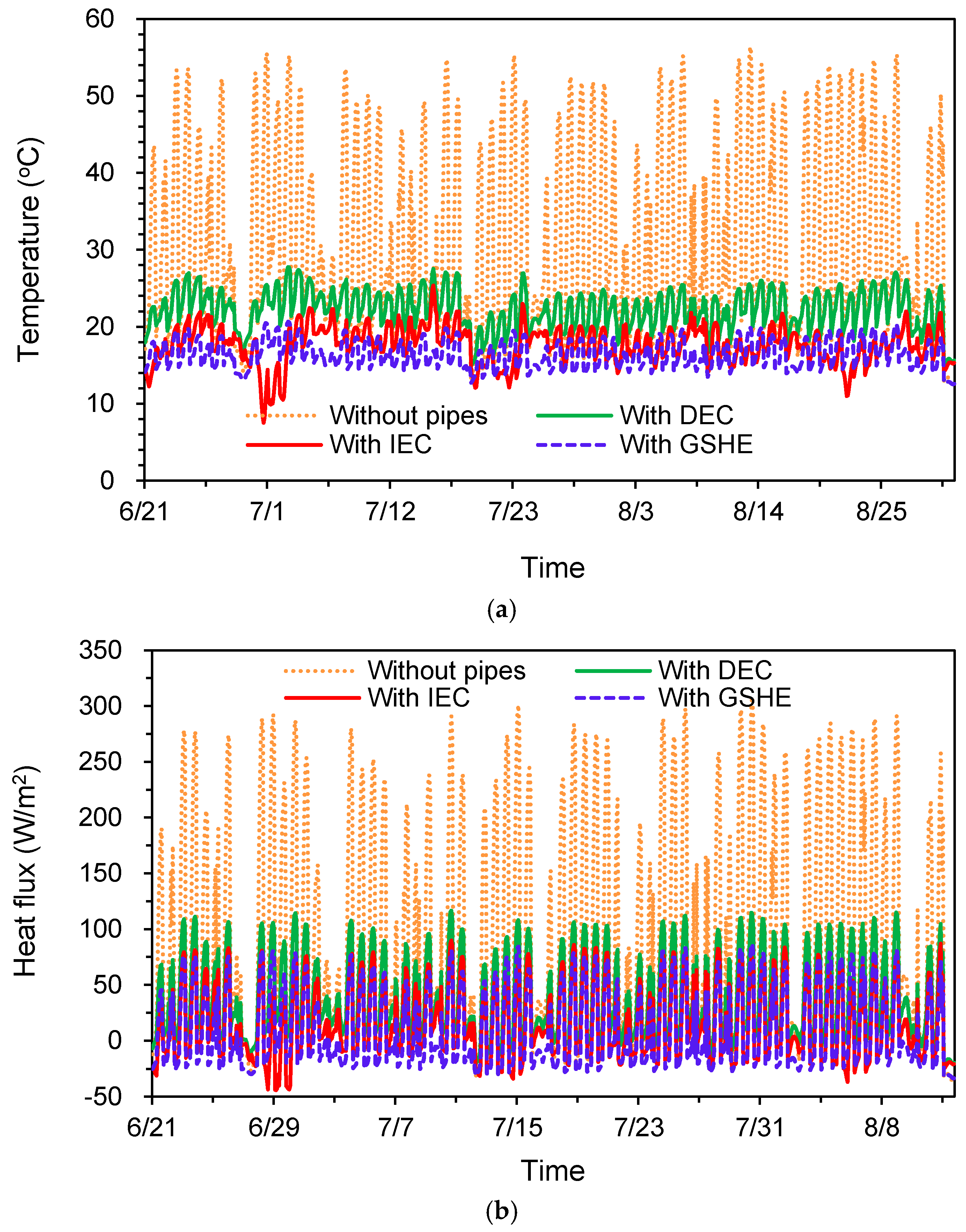
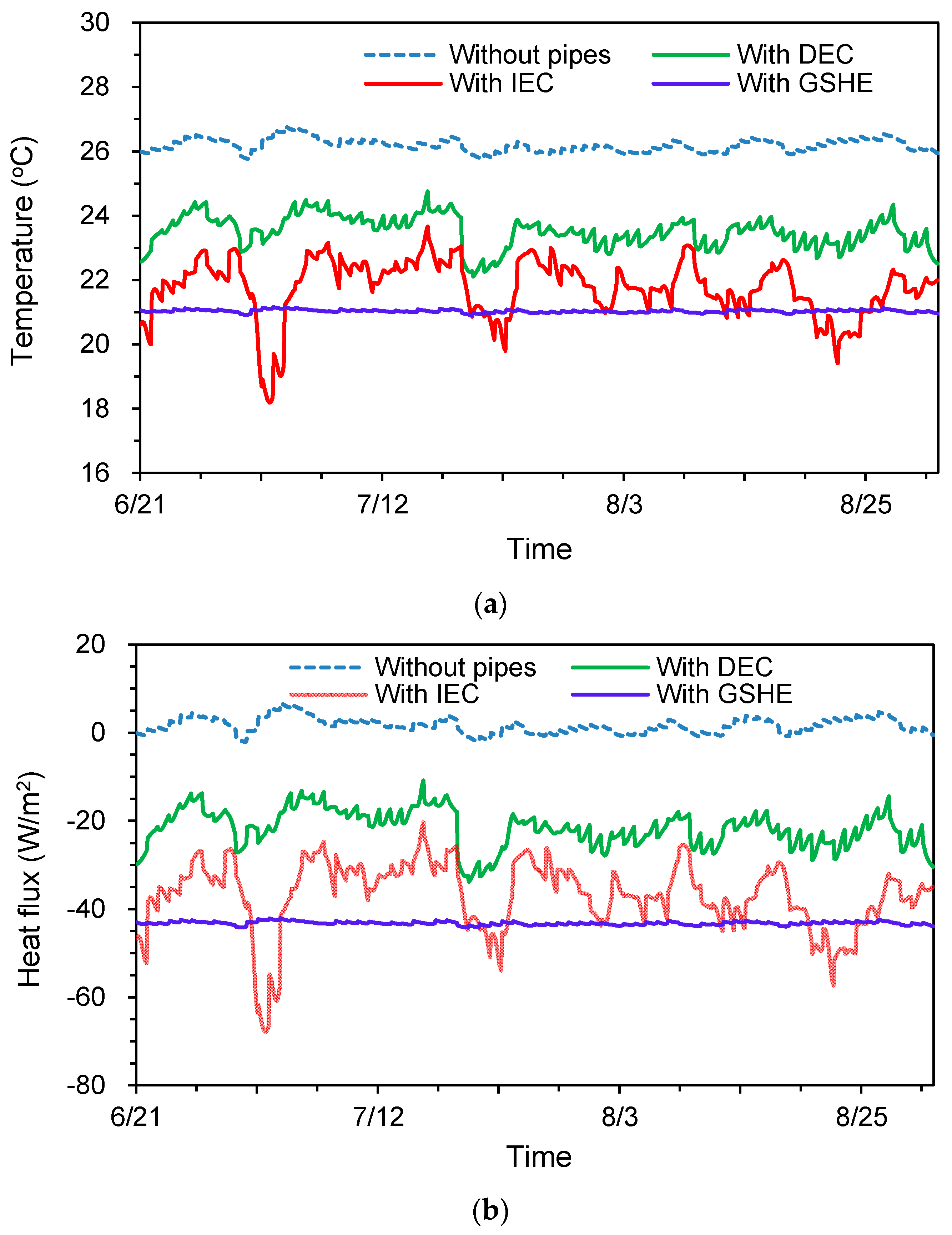
3.2. Dynamic Heat Transfer with Different Cooling Sources

The climatic data of Urumqi in summer is illustrated in Figure 8. Urumqi is a typical city in Central Asia. The ambient dry-bulb temperature is around 30 °C and the highest temperature is close to 40 °C. The solar radiation here is very intense, and the highest horizontal solar radiation is more than 1000 W/m2. Evaporative cooling is efficient here because the wet-bulb temperature and dew-point temperature are low. The average soil temperature is only 6.6 °C. Thus, DEC, IEC, and GSHE are considered as three alternative natural cooling sources in this study. The cooling effects of different sources in a complete summer are simulated and compared.
The dynamic performance of the system applied to a west orientation is analyzed as an example. The average temperature of the air cavity is demonstrated in Figure 9a. Without pipes, the average temperature of the traditional window is usually higher than 40 °C in the daytime. With the cooling pipes, the temperature of the double window is significantly reduced throughout the complete cooling season. The variation of temperature is much more stable. When DEC is employed, the seasonal average temperature of the window is 22.2 °C, which is 8.5 °C lower than the traditional double window. In addition, the temperature is already lower than the room temperature, indicating that the room will dissipate heat through the window instead of gaining heat. When IEC is employed, the seasonal average temperature of the double window is only 17.6 °C, and the cooling effect is perfect. The temperature is even lower (16.4 °C) when adopting the GSHE.
The hourly heat flux on the internal glass is illustrated in Figure 9b. In the traditional window, the heat gain in the daytime varies from 50 to 300 W/m2 owing to the large solar radiation and hot window. In regard to the window with DEC, its heat gain varies from 0 to 100 W/m2 due to the cooling effect of pipes. The accumulative seasonal heat transfer is reduced by 56.4% and the peak value is reduced by 62.2%. In regards to IEC, the heat gain varies from –20 to 60 W/m2. The accumulative heat gain is reduced by 81.9% and the peak value is reduced by 70.9%. The window will absorb the internal heat for nearly 20% of the daytime. The performance is even better in the GSHE condition, in which the accumulative heat gain is reduced by 88.2%. In this condition, the double window almost stops transferring heat to the room. However, the cooler natural cooling source has to deal with more heat because the window is cooler. The accumulative seasonal heat fluxes of the pipe are 97.4, 142.5, and 153.1 kWh/m2 in the condition of DEC, IEC, and GSHE respectively.
The seasonal effectiveness of pipes (η) is around 42.5% in the window, and the values in DEC, IEC, and GSHE conditions are very close to each other, which indicates that η represents the effectiveness of the structure of pipes regardless of the water temperature. The results show that 42.5% of the cooling energy from pipes is used for cooling the indoor space directly. The rest of the cooling energy is used to deal with the increased heat dissipation on the external skin of the window.
The temperature of the internal surface of the wall is shown in Figure 10a. The temperature of the traditional wall is more than 26 °C, but the temperature of the pipe-embedded wall is only 21 to 24 °C. The wall panel is also able to cool the indoor environment through radiative heat transfer. The thermal comfort of occupants can be improved because the mean radiant temperature is reduced. The hourly heat flux on the internal surface of the wall is illustrated in Figure 10b. With respect to the traditional wall without pipes, the heat flux varies from 0 to 10 W/m2. The heat flux is small compared with window because the insulation of the wall is better. In addition, the effect of radiation on the wall is relatively slight. However, with the built-in pipes, the heat flux becomes a negative value. The external heat cannot transfer into the room, while the internal heat is taken away by the cooling water. The cooling pipes have a similar effect as a radiant cooling panel in these conditions. The average seasonal heat flux is around −21.7 W/m2 when utilizing DEC, and the heat flux is even less when adopting IEC, which is only −36.9 W/m2. The effect of GSHE is close to that of IEC, whose average heat flux is −43.2 W/m2. In addition, due to the water temperature from GSHE being nearly independent of weather, the heat flux of the wall is very stable. The cooling capacity of these pipe-embedded walls is satisfactory.
The seasonal effectiveness of pipes (η) is around 83.0% for the pipe-embedded wall, and the values are close in the conditions with different cooling sources. η is very high for the wall because the pipes are arranged on the indoor side of the insulation layer and the insulation of the wall is better than that of glass.

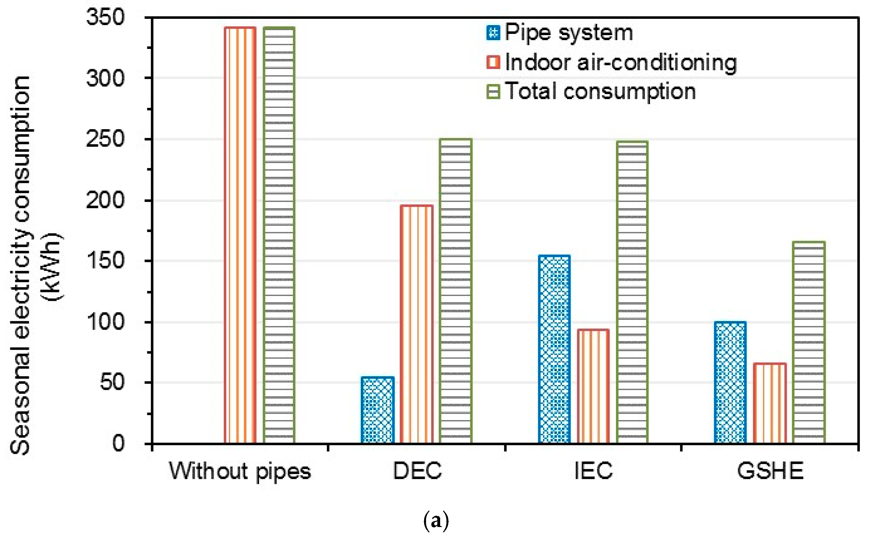
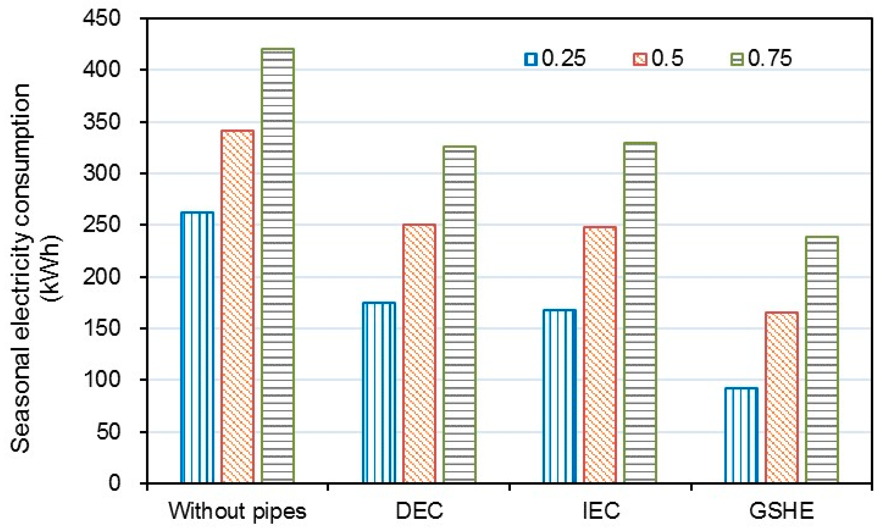
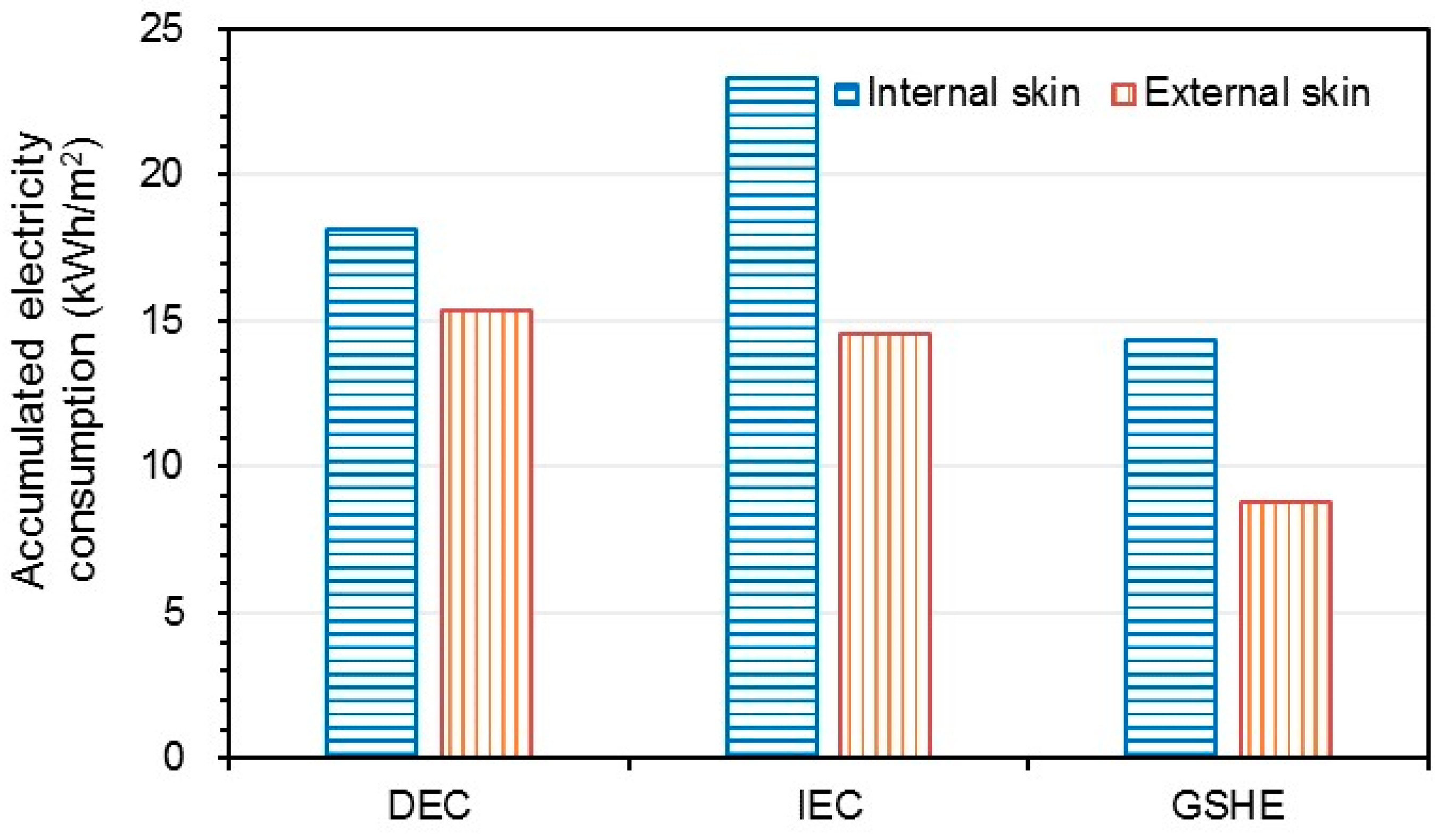
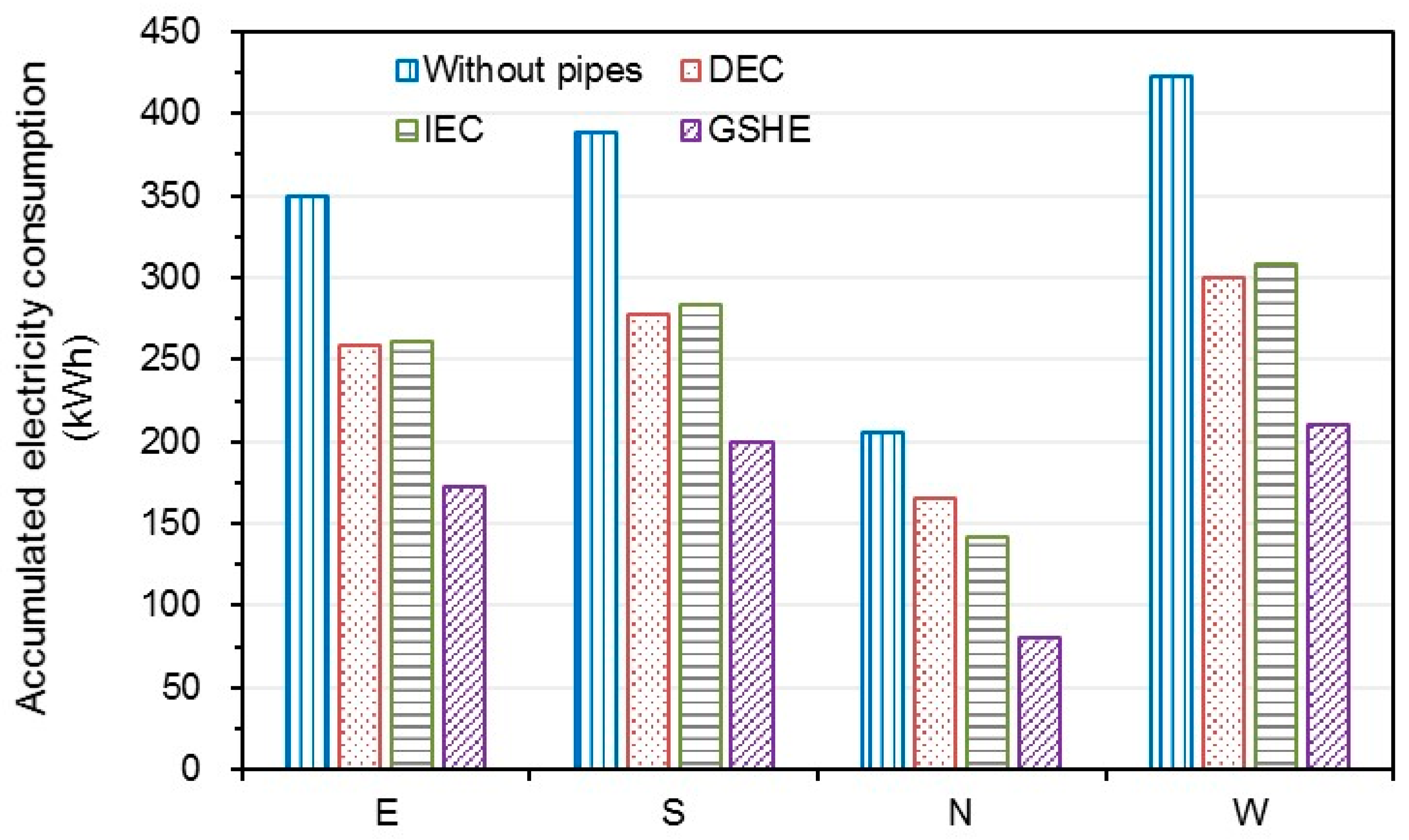
3.3. Seasonal Electricity Consumption under Different WWRs and Orientations

Traditionally, glass with good insulation (e.g., double glazing) is employed as the internal skin of a double pane window to reduce the heat conduction from the hot air cavity to the room. However, with the cooling effect of pipes, the air cavity is no longer hot. Thus, if we adopt the insulated glass to the external skin of a double pane window, the heat dissipation through the external skin can be reduced while the heat flux through the internal skin is almost constant. The seasonal electricity consumption for a window unit is shown in Figure 11. The insulated glass is placed in the internal or external skin of a window. The electricity consumption of the window with internal insulation is always higher irrespective of the cooling source. Especially for IEC and GSHE, the cooling water is cold, and the heat dissipation of the external skin is considerable. Hence, it is suggested to insulate external skin. In addition, by this method, the effectiveness of pipes (η) is increased to 60% because the cooling energy from pipes is decreased.
The seasonal electricity consumption of the pipe system and the indoor air-conditioning system in a typical office is shown in Figure 12. The WWR of the office is 0.5. The results are the average values of four orientations E, S, N, W. The accumulated heat gain of the envelope without pipes is 499.1 kWh, which takes up nearly a half of the total cooling load. This indicates the importance of improving the performance of the envelope in this region. The total electricity consumption in DEC and IEC are almost the same, with a reduction of 27% compared to the traditional system. However, their proportions of the components of electricity consumption are different. The consumption of indoor air-conditioning in IEC is much less than that in DEC because the water temperature in IEC is much lower. However, the electricity consumption for producing cooling water in IEC is much higher because its EER is lower. Overall, DEC is more suitable, considering its lower investment. The performance of GSHE is the best, where, ε is larger than 50%. The consumption of indoor air-conditioning in the GSHE condition is reduced by 81%, and its electricity consumption for the pipe system is not as high as that of IEC. In addition, GSHE does not consume extra water, which is beneficial for dry regions like Urumqi. The high efficiency of GSHE is because of the low soil temperature in these regions.
The solar radiation varies in different orientations. The accumulative radiations in the working time in summer are 163, 160, 167, and 36 kWh/m2 for E, S, W, and N orientations, respectively. It is obvious that the sunshine is stronger for E, S, and W, whereas it is weak for a N orientation. In addition, radiation is not the only factor that affects the heat gain. The average ambient air temperature is 21.7 °C from 8:00 to 11:00 and 28.0 °C from 15:00 to 18:00 in summer. Thus, it is very beneficial for the heat dissipation of east orientation because it receives radiation mainly in the morning. The seasonal electricity consumption of the office in different orientations is illustrated in Figure 13. The WWR of the office is 0.5. The results indicate that cooling pipes are effective in each orientation. The stronger the solar radiation is, the greater the reduction of electricity. However, the reduction rates of electricity consumption are close in different orientations. It is not necessary to embed the pipes for the north window because the solar radiation there is weak.
WWR is an important factor for the heat gain through the building envelope. The electricity consumption of the offices with different WWRs is shown in Figure 14. The results are the average values of four orientations, E, S, N, and W. The electricity consumption is increased with WWR in both traditional and pipe-embedded offices, but the reasons are different. In the traditional office, larger WWR means more heat will transfer through the window, and the electricity increases correspondingly. In the pipe-embedded envelope, the heat flux of the window will not grow significantly with WWR. However, the cooling surface of the wall is reduced accordingly, which will influence the cooling effect of the wall panel. With the embedded pipes, relatively large WWR is acceptable. For example, the electricity consumption of the office with GSHE (WWR = 0.75) is only 238.8 kWh, even less than that of the traditional office with a WWR of 0.25.

4. Conclusions

The energy performance of a typical office with pipe-embedded window and wall is numerically investigated in this study. The effectiveness of three natural cooling sources (DEC, IEC, GSHE) is evaluated in Urumqi. The influences of insulated glass, orientation, and WWR are considered by simulating a complete summer. The main conclusions drawn are as follows:
  • In windows, cooling pipes can remove 60% of the solar radiation directly and only less than 15% of the radiation can transfer into the room. The insulated glass should be installed to the external skin of a pipe-embedded double window to reduce the heat dissipation. The pipe effectiveness η is around 60%.
  • In walls, cooling pipes can reduce the internal surface temperature by more than 4 °C. The pipe-embedded wall becomes an efficient radiant cooling panel absorbing the heat from the room. The pipe effectiveness η is around 83%.
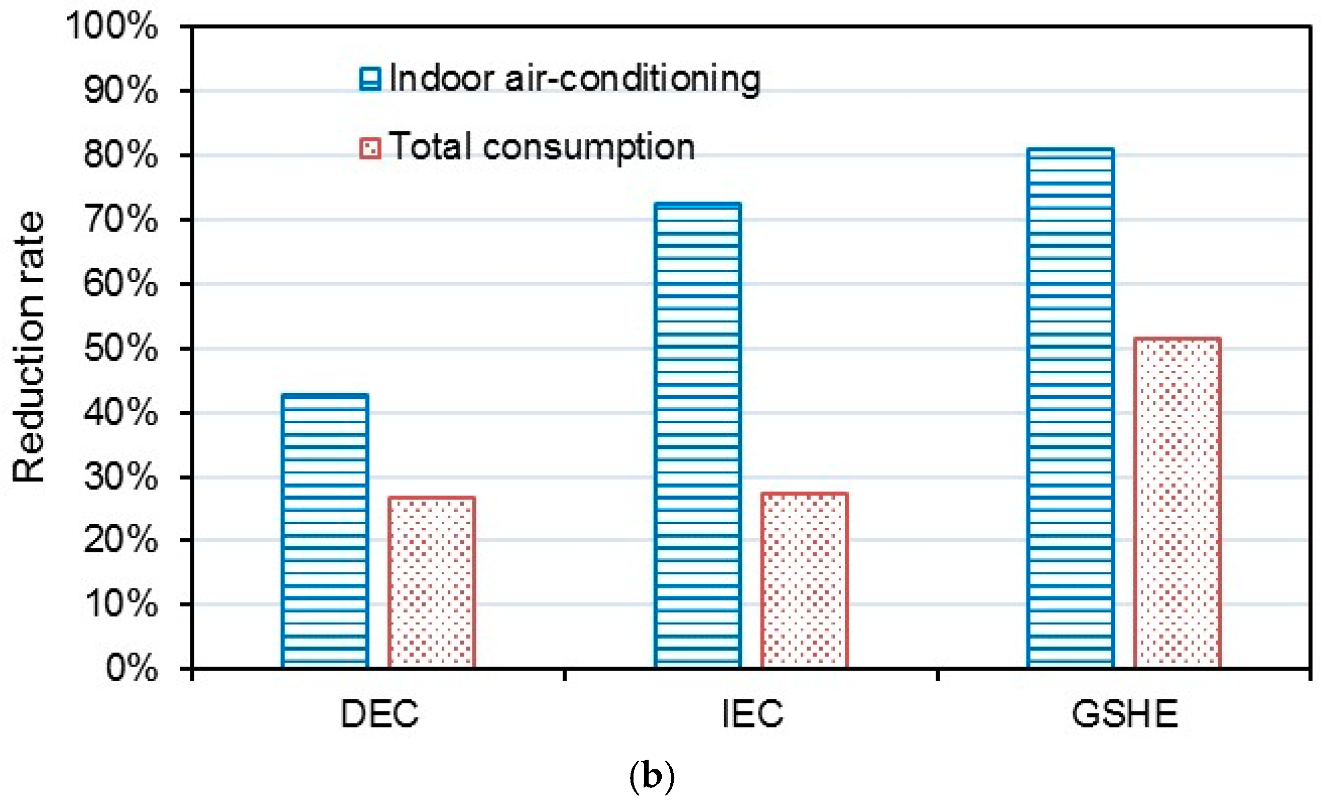
  • The seasonal cooling energy consumption of the office with pipes is reduced by 25%–50%. A large WWR is acceptable with the cooling effect of pipes.
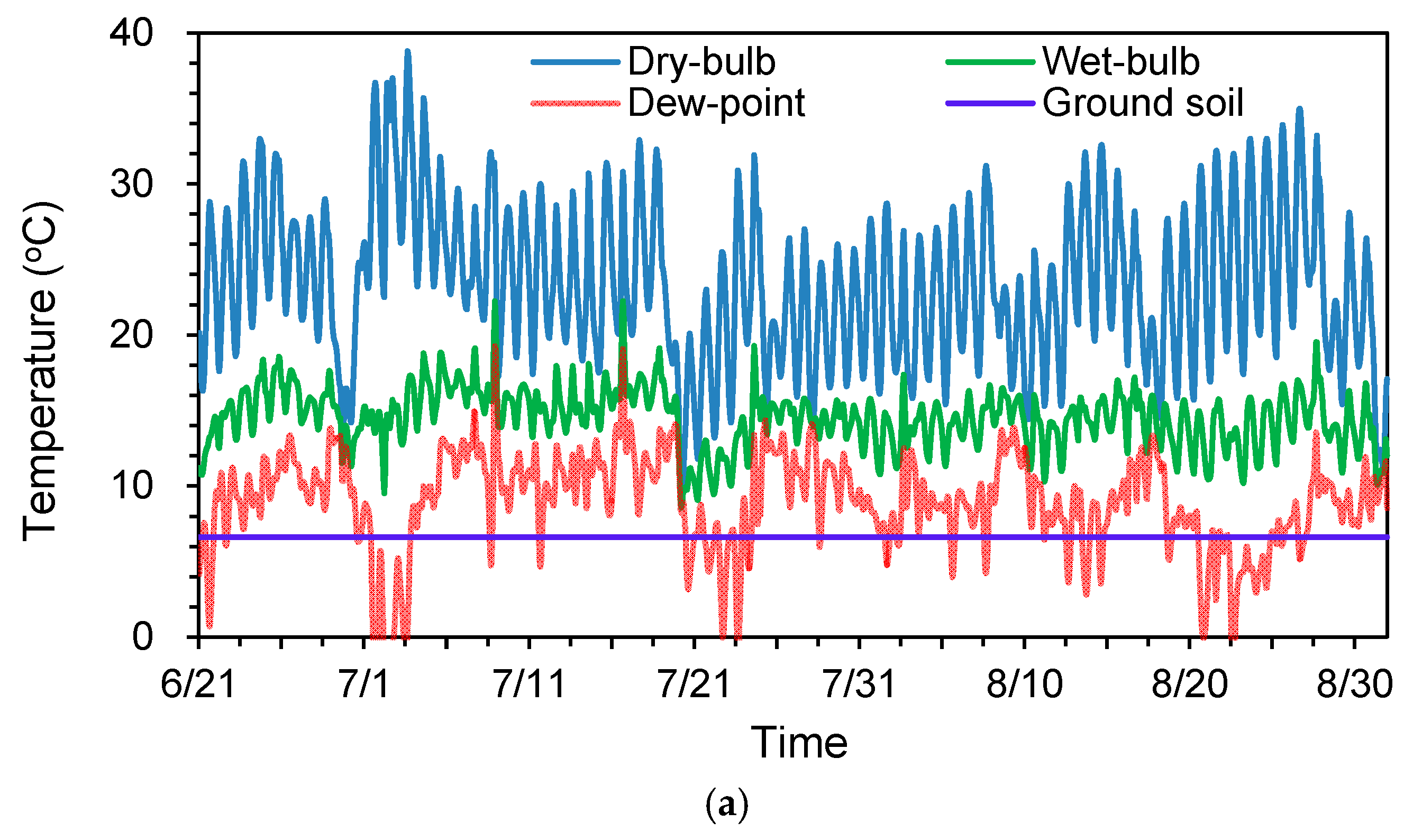
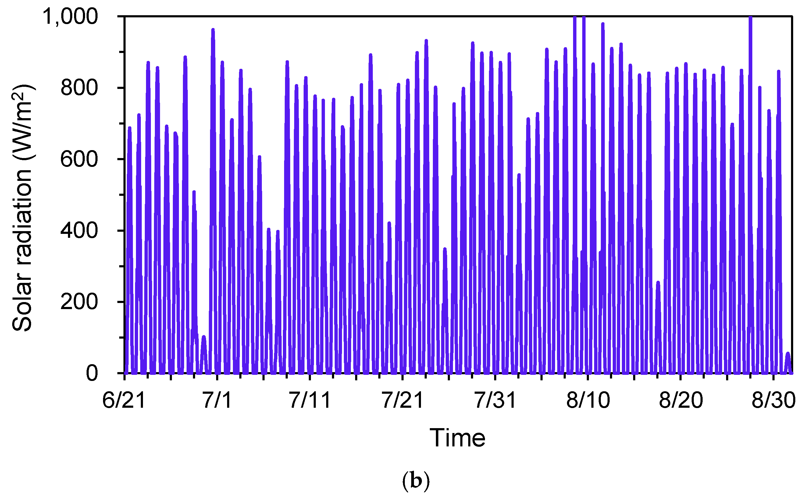
  • The performance of GSHE is the best among the three sources in Urumqi. The effectiveness of DEC and IEC is also satisfactory, with an average energy saving rate of 27%. IEC can reduce more heat flux through the envelope, but it consumes more energy to provide the cooling water.
Overall, the pipe-embedded system is very suitable for utilizing natural energy and dealing with the climate in regions like Urumqi.

Acknowledgments

This study has been supported by the National Natural Science Foundation of China (Grant No. 51638010 and 51578306).

Author Contributions

Chong Shen conducted the simulation and drafted the article. Xianting Li supervised the investigation, reviewed the manuscript and provided comments for revision of the article.

Conflicts of Interest

The authors declare no conflict of interest. The funding sponsors had no role in the design of the study; in the collection, analyses, or interpretation of data; in the writing of the manuscript, and in the decision to publish the results.

Nomenclature

Aarea, m2
Eelectricity consumption, W/m2
qheat gain, W/m2
Qcooling load, W/m2
εelectricity reduction rate of pipe-embedded envelope
ηeffectiveness of pipes
Abbreviations
DECdirect evaporative cooling
DSFdouble skin façade
EERenergy efficiency ratio
GSHEground-source heat exchanger
IECindirect evaporative cooling
WWRwindow-to-wall ratio

References

  1. Bisegna, F.; Mattoni, B.; Gori, P.; Asdrubali, F.; Guattari, C.; Evangelisti, L.; Sambuco, S.; Bianchi, F. Influence of insulating materials on green building rating system results. Energies 2016, 9, 712. [Google Scholar] [CrossRef]
  2. Ojanen, T.; Seppä, I.P.; Nykänen, E. Thermal insulation products and applications—Future road maps. Energy Procedia 2015, 78, 309–314. [Google Scholar] [CrossRef]
  3. Ji, Y.; Fitton, R.; Swan, W.; Webster, P. Assessing overheating of the UK existing dwellings—A case study of replica Victorian end terrace house. Build. Environ. 2014, 77, 1–11. [Google Scholar] [CrossRef]
  4. Sadineni, S.B.; Madala, S.; Boehm, R.F. Passive building energy savings: A review of building envelope components. Renew. Sustain. Energy Rev. 2011, 15, 3617–3631. [Google Scholar] [CrossRef]
  5. Pargana, N.; Pinheiro, M.D.; Silvestre, J.D.; de Brito, J. Comparative environmental life cycle assessment of thermal insulation materials of buildings. Energy Build. 2014, 82, 466–481. [Google Scholar] [CrossRef]
  6. Hidalgo, J.P.; Welch, S.; Torero, J.L. Performance criteria for the fire safe use of thermal insulation in buildings. Constr. Build. Mater. 2015, 100, 285–297. [Google Scholar] [CrossRef]
  7. Bahaj, A.S.; James, P.A.B.; Jentsch, M.F. Potential of emerging glazing technologies for highly glazed buildings in hot arid climates. Energy Build. 2008, 40, 720–731. [Google Scholar] [CrossRef]
  8. Garrison, J.D.; Collins, R.E. Manufacture and cost of vacuum glazing. Sol. Energy 1995, 55, 151–161. [Google Scholar] [CrossRef]
  9. Manz, H.; Brunner, S.; Wullschleger, L. Triple vacuum glazing: Heat transfer and basic mechanical design constraints. Sol. Energy 2006, 80, 1632–1642. [Google Scholar] [CrossRef]
  10. Mohelnikova, J. Materials for reflective coatings of window glass applications. Constr. Build. Mater. 2009, 23, 1993–1998. [Google Scholar] [CrossRef]
  11. Hong, T.; Kim, J.; Lee, J.; Koo, C.; Park, H. Assessment of seasonal energy efficiency strategies of a double skin façade in a monsoon climate region. Energies 2013, 6, 4352–4376. [Google Scholar] [CrossRef]
  12. Cetiner, I.; Özkan, E. An approach for the evaluation of energy and cost efficiency of glass façades. Energy Build. 2005, 37, 673–684. [Google Scholar] [CrossRef]
  13. Chan, A.L.S.; Chow, T.T.; Fong, K.F.; Lin, Z. Investigation on energy performance of double skin façade in Hong Kong. Energy Build. 2009, 41, 1135–1142. [Google Scholar] [CrossRef]
  14. Shen, C.; Li, X. Thermal performance of double skin façade with built-in pipes utilizing evaporative cooling water in cooling season. Sol. Energy 2016, 137, 55–65. [Google Scholar] [CrossRef]
  15. Parra, J.; Guardo, A.; Egusquiza, E.; Alavedra, P. Thermal performance of ventilated double skin façades with venetian blinds. Energies 2015, 8, 4882–4898. [Google Scholar] [CrossRef] [Green Version]
  16. Manz, H. Total solar energy transmittance of glass double façades with free convection. Energy Build. 2004, 36, 127–136. [Google Scholar] [CrossRef]
  17. Gratia, E.; De Herde, A. Greenhouse effect in double-skin facade. Energy Build. 2007, 39, 199–211. [Google Scholar] [CrossRef]
  18. Xu, X.; Wang, S.; Wang, J.; Xiao, F. Active pipe-embedded structures in buildings for utilizing low-grade energy sources: A review. Energy Build. 2010, 42, 1567–1581. [Google Scholar] [CrossRef]
  19. Shen, C.; Li, X. Dynamic thermal performance of pipe-embedded building envelope utilizing evaporative cooling water in the cooling season. Appl. Therm. Eng. 2016, 106, 1103–1113. [Google Scholar] [CrossRef]
  20. Li, A.; Xu, X.; Sun, Y. A study on pipe-embedded wall integrated with ground source-coupled heat exchanger for enhanced building energy efficiency in diverse climate regions. Energy Build. 2016, 121, 139–151. [Google Scholar] [CrossRef]
  21. Shen, C.; Li, X. Solar heat gain reduction of double glazing window with cooling pipes embedded in venetian blinds by utilizing natural cooling. Energy Build. 2016, 112, 173–183. [Google Scholar] [CrossRef]
  22. Ministry of Housing Urban-Rural Development. National Standard GB 50736-2012-Code for Design of Heating Ventilation and Air Conditioning; Ministry of Housing Urban-Rural Development: Beijing, China, 2012.
  23. Zeng, Z.; Li, X.; Li, C.; Zhu, Y. Modeling ventilation in naturally ventilated double-skin façade with a venetian blind. Build. Environ. 2012, 57, 1–6. [Google Scholar] [CrossRef]
  24. Iyi, D.; Hasan, R.; Penlington, R.; Underwood, C. Double skin façade: Modelling technique and influence of venetian blinds on the airflow and heat transfer. Appl. Therm. Eng. 2014, 71, 219–229. [Google Scholar] [CrossRef]
  25. Xie, J.; Zhu, Q.; Xu, X. An active pipe-embedded building envelope for utilizing low-grade energy sources. J. Cent. South Univ. 2012, 19, 1663–1667. [Google Scholar] [CrossRef]
  26. Lu, Y. Practical Design Handbook for HVAC, 2nd ed.; China Building Industry Press: Beijing, China, 2008. [Google Scholar]
  27. Saelens, D.; Roels, S.; Hens, H. Strategies to improve the energy performance of multiple-skin facades. Build. Environ. 2008, 43, 638–650. [Google Scholar] [CrossRef]
  28. Shen, C.; Li, X. Energy saving potential of pipe-embedded building envelope utilizing low-temperature hot water in the heating season. Energy Build. 2017, 138, 318–331. [Google Scholar] [CrossRef]
  29. China Meteorological Administration. Weather Database for Analyzing the Building Thermal Environment in China, 1st ed.China Architectural & Building Press: Beijing, China, 2005.
  30. Klimanek, A.; Cedzich, M.; Białecki, R. 3D CFD modeling of natural draft wet-cooling tower with flue gas injection. Appl. Therm. Eng. 2015, 91, 824–833. [Google Scholar] [CrossRef]
  31. Duan, Z.; Zhan, C.; Zhang, X.; Mustafa, M.; Zhao, X.; Alimohammadisagvand, B.; Hasan, A. Indirect evaporative cooling: Past, present and future potentials. Renew. Sustain. Energy Rev. 2012, 16, 6823–6850. [Google Scholar] [CrossRef]
  32. Zhu, Y. Built Environment, 3rd ed.; China Architectural & Building Press: Beijing, China, 2010. [Google Scholar]
  33. Wu, W.; Wang, B.; You, T.; Shi, W.; Li, X. A potential solution for thermal imbalance of ground source heat pump systems in cold regions: Ground source absorption heat pump. Renew. Energy 2013, 59, 39–48. [Google Scholar] [CrossRef]
  34. National Development and Reform Commission. National Standard GB/T 17981-2007-Economic Operation of Air Conditioning Systems; National Development and Reform Commission: Beijing, China, 2008.
  35. Duan, Z. Investigation of a Novel Dew Point Indirect Evaporative Air Conditioning System for Buildings. Ph.D. Thesis, The University of Nottingham, Nottingham, UK, September 2011. [Google Scholar]
Figure 1. Sketch of the pipe-embedded envelope connected with natural sources.
Energies 10 00366 g001
Figure 2. Configuration of the simulated office: (a) Office with traditional envelope and (b) Synthetic pipe-embedded envelope.
Energies 10 00366 g002
Figure 3. Structures and dimensions of the simulated envelope: (a) Pipe-embedded window and (b) Pipe-embedded wall.
Energies 10 00366 g003
Figure 4. Results from different mesh densities.
Energies 10 00366 g004
Figure 5. Mesh configurations: (a) Pipe-embedded window and (b) Pipe-embedded wall.
Energies 10 00366 g005
Figure 6. Cross section of the window: (a) Temperature distribution and (b) Velocity distribution.
Energies 10 00366 g006
Figure 7. Temperature field of a wall during typical times of a day.
Energies 10 00366 g007
Figure 8. Climatic data of Urumqi: (a) Temperature of different sources and (b) Horizontal solar radiation.
Energies 10 00366 g008aEnergies 10 00366 g008b
Figure 9. Heat transfer in different windows: (a) Temperature variation and (b) Heat flux variation.
Energies 10 00366 g009
Figure 10. Heat transfer in different walls: (a) Temperature variation and (b) Heat flux variation.
Energies 10 00366 g010
Figure 11. Accumulated electricity consumption for window with different insulation layouts.
Energies 10 00366 g011
Figure 12. Seasonal electricity consumption of the office: (a) Accumulated amount and (b) Reduction rate.
Energies 10 00366 g012aEnergies 10 00366 g012b
Figure 13. Seasonal electricity consumption of the offices in different orientations.
Energies 10 00366 g013
Figure 14. Seasonal electricity consumption of the offices with different WWRs.
Energies 10 00366 g014
Table 1. Physical parameters of the window materials.
ComponentsInternal SkinExternal SkinVenetian Blinds
MaterialDouble glazingStaliniteAluminum alloy
Thickness (mm)6 + 12 (air) + 692
Specific heat (J/kg·K)100840880
Density (kg/m3)100022002700
Heat conductivity coefficient (W/(m·K))0.090.28180
Transmissivity-SW 1 (%)65860
Absorptivity-SW (%)17780
Reflectivity-SW (%)18720
Transmissivity-LW 2 (%)34500
Absorptivity-LW (%)484090
Reflectivity-LW (%)181010
1 SW: short wave band, 0–2.7 μm. 2 LW: long wave band, 2.7–1000 μm.
Table 2. Physical properties of the wall materials.
MaterialsCement PlasterCrushed Stone ConcreteExpanded PerliteClay Brick
Thermal conductivity (W/(m·K))0.931.510.0650.81
Density (kg/m3)180024006701800
Specific heat (J/(kg·K))8379202501050

