Article

A Novel High-Frequency Voltage Standing-Wave Ratio-Based Grounding Electrode Line Fault Supervision in Ultra-High Voltage DC Transmission Systems

1
State Grid Sichuan Electric Power Research Institute, Chengdu 610072, China
2
School of Energy Science and Engineering, University of Electronic Science and Technology of China, Chengdu 611731, China
3
Department of Electrical Engineering, Xi’an Jiaotong University, Xi’an 710049, China
*
Author to whom correspondence should be addressed.
Energies 2017, 10(3), 309; https://doi.org/10.3390/en10030309
Submission received: 28 December 2016 / Revised: 21 February 2017 / Accepted: 28 February 2017 / Published: 5 March 2017
(This article belongs to the Collection Smart Grid)

Abstract

:
In order to improve the fault monitoring performance of grounding electrode lines in ultra-high voltage DC (UHVDC) transmission systems, a novel fault monitoring approach based on the high-frequency voltage standing-wave ratio (VSWR) is proposed in this paper. The VSWR is defined considering a lossless transmission line, and the characteristics of the VSWR under different conditions are analyzed. It is shown that the VSWR equals 1 when the terminal resistance completely matches the characteristic impedance of the line, and when a short circuit fault occurs on the grounding electrode line, the VSWR will be greater than 1. The VSWR will approach positive infinity under metallic earth fault conditions, whereas the VSWR in non-metallic earth faults will be smaller. Based on these analytical results, a fault supervision criterion is formulated. The effectiveness of the proposed VSWR-based fault supervision technique is verified with a typical UHVDC project established in Power Systems Computer Aided Design/Electromagnetic Transients including DC(PSCAD/EMTDC). Simulation results indicate that the proposed strategy can reliably identify the grounding electrode line fault and has strong anti-fault resistance capability.

1. Introduction

UHVDC projects play an important role in modern long-distance electrical power delivery [1,2] because of their capability of delivering massive electricity transmission capacity over long distances in a controllable way [3,4]. The grounding electrode is an essential part in the UHVDC project in that it provides the current loop from the pole to the earth and acts as an unbalance reference between two poles. In practice, the grounding electrode is sited far from the converter station via two parallel grounding wires, to avoid the impact of the DC magnetic bias at the converter stations [5,6]. Therefore, the protection strategies and supervision devices for grounding electrode line faults are very important in practical UHVDC projects.
A typical UHVDC earth electrode design can be found in [7]. Normally, the grounding electrode line comprises two parallel lines without separate switches, therefore, the two parallel lines always function as one line in practice. The unbalanced current protection is generally equipped for the earth electrode line, and improvement measures were proposed to enhance the reliability of the existing unbalanced current protection strategy [8]. The authors in [9] proposed a fast tripping scheme by inserting DC breakers into both grounding electrode lines. The control and protection strategies were revised, in order to avoid the blockage of the other pole if one pole was blocked and failed to restart. In [10], by considering the characteristics of grounding electrode line faults, it was suggested that the unbalanced current protection system should adopt fault location and the inverse-time function. The authors in [11] proposed to integrate differential current protections with the existing unbalanced current protection to realize fast and accurate location of electrode grounding line faults. However, the proposed current-based protection strategy can only be used in monopolar earth return mode and cannot work under conditions where the UHVDC system operates in bipolar earth return mode or monopolar metallic return mode, because there is no current in the grounding electrode line under these operation modes. It is also noted that the monopolar earth return configuration is not commonly used because the return current via earth may endanger the surrounding human beings or animals [12]. Therefore, current-based protection techniques are not applicable for grounding electrode lines in practical UHVDC projects.
In order to solve the grounding electrode line fault problem in bipolar balanced operation mode, a high-frequency impedance measurement technique for grounding electrode line fault supervision, in which the impedance was detected by injecting a high-frequency current source, was proposed in [13]. In such methods, the voltage variation can also be used as the indication of fault or not [14]. This approach is widely adopted in UHVDC projects because it is applicable for all the operation modes. However, in practice it is found that such schemes may fail to operate under conditions of earth faults via transition resistance. The incorrect operation of grounding electrode lines, due to defects in the protection system, has caused many faults in practical UHVDC projects in recent years, leading to great economic losses, so it is of great importance to develop an electrode grounding line fault detection system with better performance.
In this paper, a novel fault monitoring algorithm based on the high-frequency voltage standing-wave ratio (VSWR) principle is proposed, by combining the high-frequency signal injection and traveling wave fault detection technique. The traveling wave based fault detection is widely utilized because it has the ability to operate fast and overcomes the challenge from the earth fault via high transition resistance. The characteristics of the VSWR on the long-distance lossless transmission line are investigated, and the performance of the proposed approach is studied by comparing with existing grounding electrode line fault detection systems under various operation conditions.
The rest of this paper is organized as follows: Section 2 briefly introduces the principle and evaluates the performance of the existing high-frequency impedance detection method. Then Section 3 mainly presents the definition and calculation of the high-frequency VSWR. The characteristics of the high-frequency VSWR is analyzed, and then a novel grounding electrode line fault supervision methodology based on the high-frequency VSWR is proposed. The proposed method is verified by conducting simulations on PSCAD/EMTDC platform in Section 4. Finally, conclusions are presented in Section 5.

2. Overview of High-Frequency Impedance Supervision Technique for Grounding Electrode Line Fault

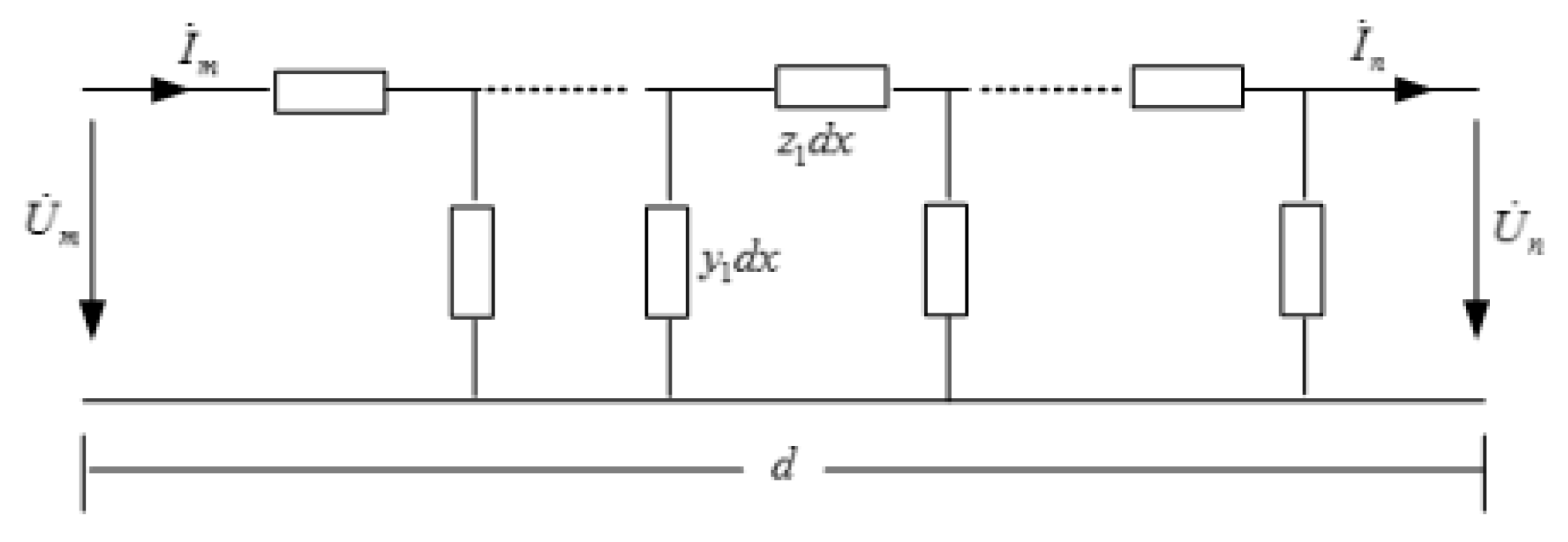
2.1. The Operation Principle

Figure 1 illustrates a typical grounding electrode line impedance supervision (ELIS) system configured within a UHVDC system. ELIS is used to continuously monitor the status of the electrode line. A high-frequency AC current is injected into the electrode line and the voltage to ground at the injection point is measured. Following the practice in all HVDC projects of the Chinese state grid, the frequency of the injected signal is chosen as 13.95 kHz [15]. The impedance is calculated from the current and voltage and is used as a measure of the conditions of the electrode line. At the two terminals of the grounding electrode line, a blocking filter is installed to block the injected high-frequency current. At the electrode station side terminal the blocking filter is also provided with a resistor, whose resistance corresponds to the characteristic impedance of the electrode line. Such a configuration ensures a reflection free termination. With less reflection at the line terminations, impedance shifts caused by a fault can be better defined, making fault detection more accurate, especially for faults close to the electrode.
A sudden change of the measured impedance value is the criterion for an electrode line fault (open circuit or grounding fault). ELIS may alarm if the change is greater than a certain value. The voltage and current at the converter end of the grounding electrode line are measured to calculate the high-frequency impedance. It is found that the measured high-frequency impedance is a periodic function of the fault distance [12]. Therefore, the operation of ELIS is different from the distance relay. Equation (1) defines the operation condition of ELIS, which is illustrated in Figure 2:
| Z ˙ m Z ˙ r e f | Z s e t ,
where Z ˙ m represents the calculated high-frequency impedance based on the voltage and current at the converter end. Z ˙ r e f is the reference impedance calculated with electrode line parameters under normal operation. Z s e t is the threshold setting, usually 30 Ω [15].

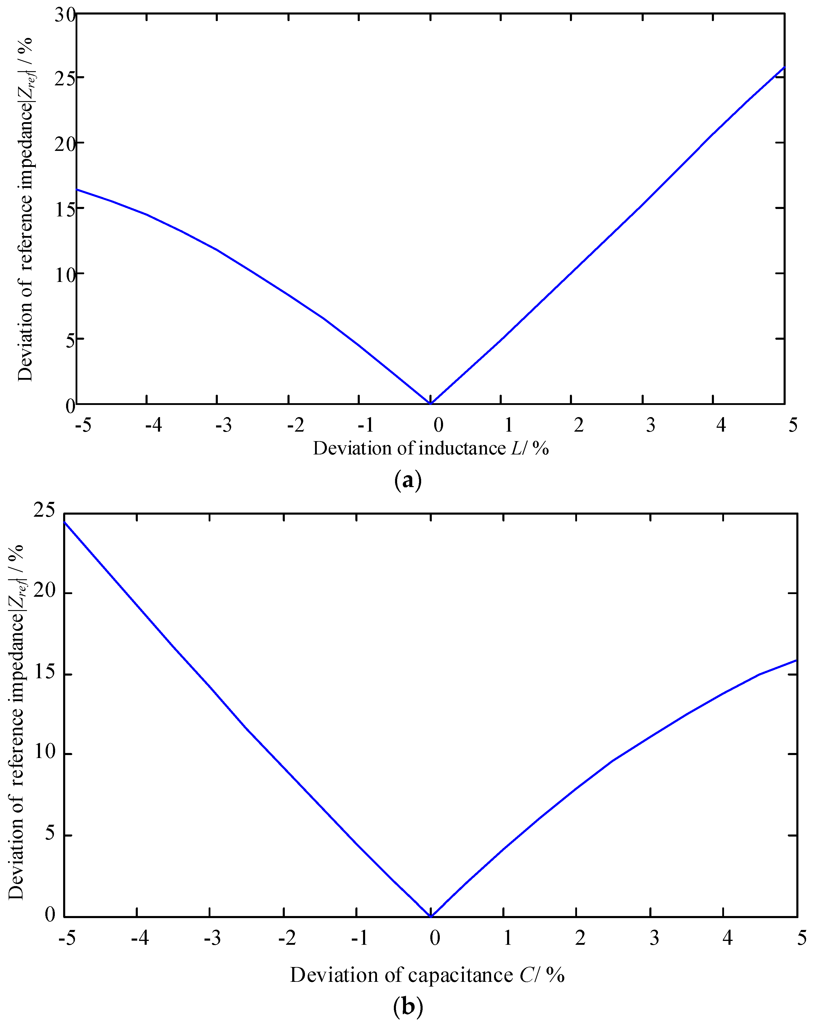
2.2. Performance Evaluation of Conventional ELIS Technique

It can be seen that Z ˙ r e f is related to the electrode line parameters, such as the resistance, inductance and capacitance. In reality, the values of resistance, inductance, and capacitance of the grounding electrode line are measured at fundamental frequency, while the injected high-frequency current is 13.95 kHz. Furthermore, the parameters change with temperature, aging processes, humidity and other factors. Thus the measured grounding electrode line parameters are not guaranteed to be equal to the actual values, so that the high-frequency impedance based system may operate erroneously.
Assume Z · r e f r e a l and Z · r e f m e a s are, respectively, the reference impedance calculated with the actual electrode line parameters and the measured electrode line parameters. Obviously, the reference impedance is a function of line inductance L and line capacitance C. The difference between Z · r e f r e a l and Z · r e f m e a s caused by the variation of L and C can be represented as follows after neglecting the third and higher order terms:
Z · r e f m e a s Z · r e f r e a l = Z · r e f r e a l ( L r , C r ) L ( L m L r ) + Z · r e f r e a l ( L r , C r ) C ( C m C r ) + 1 2 2 Z · r e f r e a l ( L r , C r ) L 2 ( L m L r ) 2 + 2 Z · r e f r e a l ( L r , C r ) L C ( L m L r ) ( C m C r ) + 1 2 2 Z · r e f r e a l ( L r , C r ) C 2 ( C m C r ) 2
where, Lr and Cr are the real line parameter values. Lm and Cm are the measured line parameter values.
According to (2), we can obtain the effect of line parameter variations on the reference impedance, as shown in Figure 3. It can be seen in Figure 3 that a 5% deviation of inductance or capacitance will result in more than 15% deviation of the reference impedance Zref. That is to say, the reference impedance Zref is sensitive to the line parameters. The traditional ELIS technique subject to mal-operation due to the variations of line parameters.
The measured values listed in Table 1 are the per-unit length values of resistance, inductance and capacitance of the electrode line for Yibin-Jinhua ±800 kV DC transmission project in China. The measured values are obtained using the measuring methods described in [16]. The real values of the line parameters are unknown. In order to illustrate the performance of the conventional ELIS, the real capacitance value is considered to be 1% deviation from the measured one, as listed in Table 1. The reference impedance Z r e f r e a l and Z r e f m e a s are [14]:
Z r e f r e a l = 247.326 + j 7.399   Ω Z r e f m e a s = 251.482 + j 17.2853   Ω
Suppose that a metallic short circuit fault occurs on the grounding electrode line at 4 km away from the converter end. The measured high-frequency impedance under fault condition is Z m = 249.234 + j 42.4819 Ω . Thus the operation conditions of ELIS with actual reference impedance and the measured reference impedance are:
| Z m Z r e f r e a l | = 35.14   Ω | Z m Z r e f m e a s | = 25.30   Ω
This shows that the difference between the calculated high-frequency impedance Z m under fault conditions and the actual reference impedance Z r e f r e a l is greater than the threshold. The ELIS should send alarm information under such conditions. However, the difference between the calculated high-frequency impedance Z m and the reference impedance Z r e f m e a s is less than the threshold. The ELIS will not take any actions.

3. The VSWR Technique for Grounding Electrode Line Fault

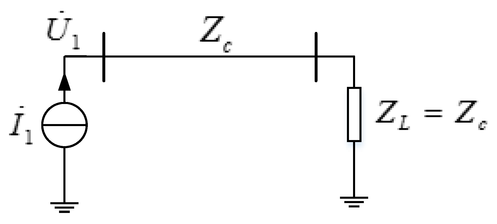
3.1. VSWR on a Lossless Transmission Line

Generally, standing waves are formed by the overlap of two waves with the same frequency but opposite directions. The maximum amplitude appears at the position termed as the wave peak whereas the minimum amplitude position is called wave valley. Under normal operation, the standing wave effect can be neglected because the wavelength of the fundamental frequency wave is far greater than the length of the transmission lines. For the injected high frequency current, the standing waves can be utilized in the grounding electrode line fault supervision techniques.
Figure 4 is a typical distributed circuit model of a lossless transmission line. The characteristic equations of voltage and current, which will be used for later derivation, are rewritten below:
U ˙ = A 1 e γ x + A 2 e γ x I ˙ = A 1 Z c e γ x A 2 Z c e γ x ,
where γ is the transmission propagation constant, and γ = j ω L 0 C 0 . Z c = z 1 / y 1 = ( r 1 + j ω l 1 ) / ( g 1 + j ω c 1 ) is the characteristic impedance of the transmission line. For the lossless transmission line, r1 and g1 are set to zero, thus Z c = z 1 / y 1 = l 1 / c 1 . A1 and A2 are the coefficient determined by the voltage and current at the two ends of the line.
Assuming that the end point of the transmission line is x = 0, the voltage at the end of the transmission line is U0, and the load impedance is ZL. The voltage and current at position x on the transmission line is:
U ( x ) = U 0 ( e γ x + Γ L e γ x ) I ( x ) = U 0 Z c ( e γ x Γ L e γ x ) ,
where, Γ L is the reflection coefficient at the load side:
Γ L = Z L Z c Z L + Z c = Z L / Z c 1 Z L / Z c + 1 = Z L n 1 Z L n + 1 ,
where, ZLn is the normalized load impedance.
The high-frequency VSWR is defined as the ratio of voltage amplitudes at the wave peak and the adjacent wave valley on the transmission line, as follows:
V S W R = | U ( x ) | max | U ( x ) | min = 1 + | Γ L | 1 | Γ L | ,

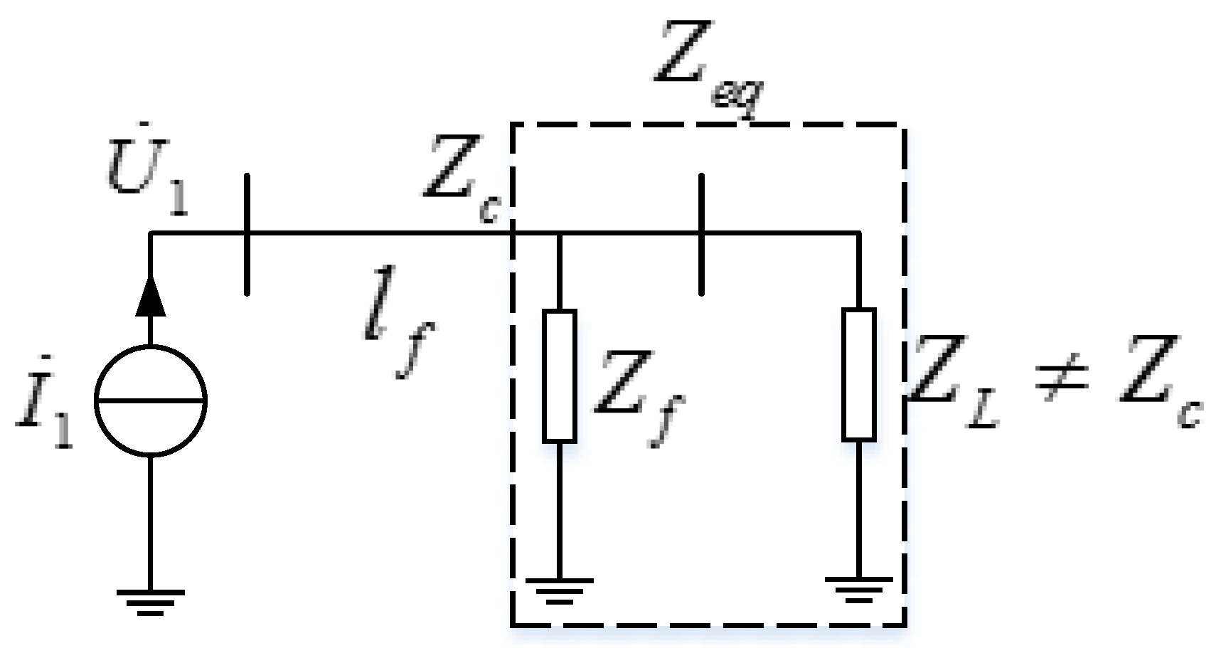
3.2. Calculation of VSWR

In practice, the VSWR on the grounding electrode line is easily obtained if the terminal voltage and current are given. Assume that the voltage and current at the converter station end of the grounding electrode line, U ˙ 1 and I ˙ 1 , are measured, then the voltage and current at the point x can be calculated as follows, from (5):
U ˙ ( x ) = 1 2 ( U ˙ 1 + Z c I ˙ 1 ) e γ x + 1 2 ( U ˙ 1 Z c I ˙ 1 ) e γ x I ˙ ( x ) = 1 2 ( U ˙ 1 Z c + I ˙ 1 ) e γ x 1 2 ( U ˙ 1 Z c I ˙ 1 ) e γ x ,
For a lossless transmission line, the transmission propagation constant γ = j ω L 0 C 0 is a pure imaginary number. Therefore, (9) can be rewritten as:
U ˙ ( x ) = U ˙ 1 cos β x j Z c I ˙ 1 sin β x I ˙ ( x ) = I ˙ 1 cos β x j U ˙ 1 Z c sin β x ,
where, β = ω L 0 C 0 is the phase constant.
Assuming that the phase angle of the current at the converter station end is zero, then the voltage measured at this point is:
U ˙ 1 = U s ( cos ϕ u 1 + j sin ϕ u 1 ) I ˙ 1 = I s ,
where, US and IS are the amplitudes of the measured voltage and current at the converter station end on the grounding electrode line, respectively. ϕ u 1 is the phase difference between U ˙ 1 and I ˙ 1 .
Substituting into (10), one has:
U ˙ ( x ) = U s cos ϕ u 1 cos β x + j ( U s sin ϕ u 1 cos β x Z c I s sin β x ) ,
| U ˙ ( x ) | 2 = 1 2 ( U s 2 + Z c 2 I s 2 ) + ( 1 2 U s 2 1 2 Z c 2 I s 2 ) cos 2 β x U s Z c I s sin ϕ u 1 sin 2 β x
Let:
A c = ( 1 2 U s 2 1 2 Z c 2 I s 2 ) 2 + U s 2 Z c 2 I s 2 sin 2 ϕ u 1 ,
The maximum and minimum of the voltage amplitude and the VSWR can be calculated:
| U ˙ ( x ) | max 2 = 1 2 ( U s 2 + Z c 2 I s 2 ) + A c | U ˙ ( x ) | min 2 = 1 2 ( U s 2 + Z c 2 I s 2 ) A c ,
V S W R = 1 2 ( U s 2 + Z c 2 I s 2 ) + A c 1 2 ( U s 2 + Z c 2 I s 2 ) A c ,
Therefore, once the transmission parameters of the grounding electrode line are known, the VSWR can be easily calculated using the measured voltage amplitudes, current amplitudes, and the phase angles. Equation (16) shows that the VSWR along the transmission line is independent of the distance x, but only determined by voltage US and current IS, their phase angle ϕ u 1 , and the internal characteristics of the grounding line, such as Zc.

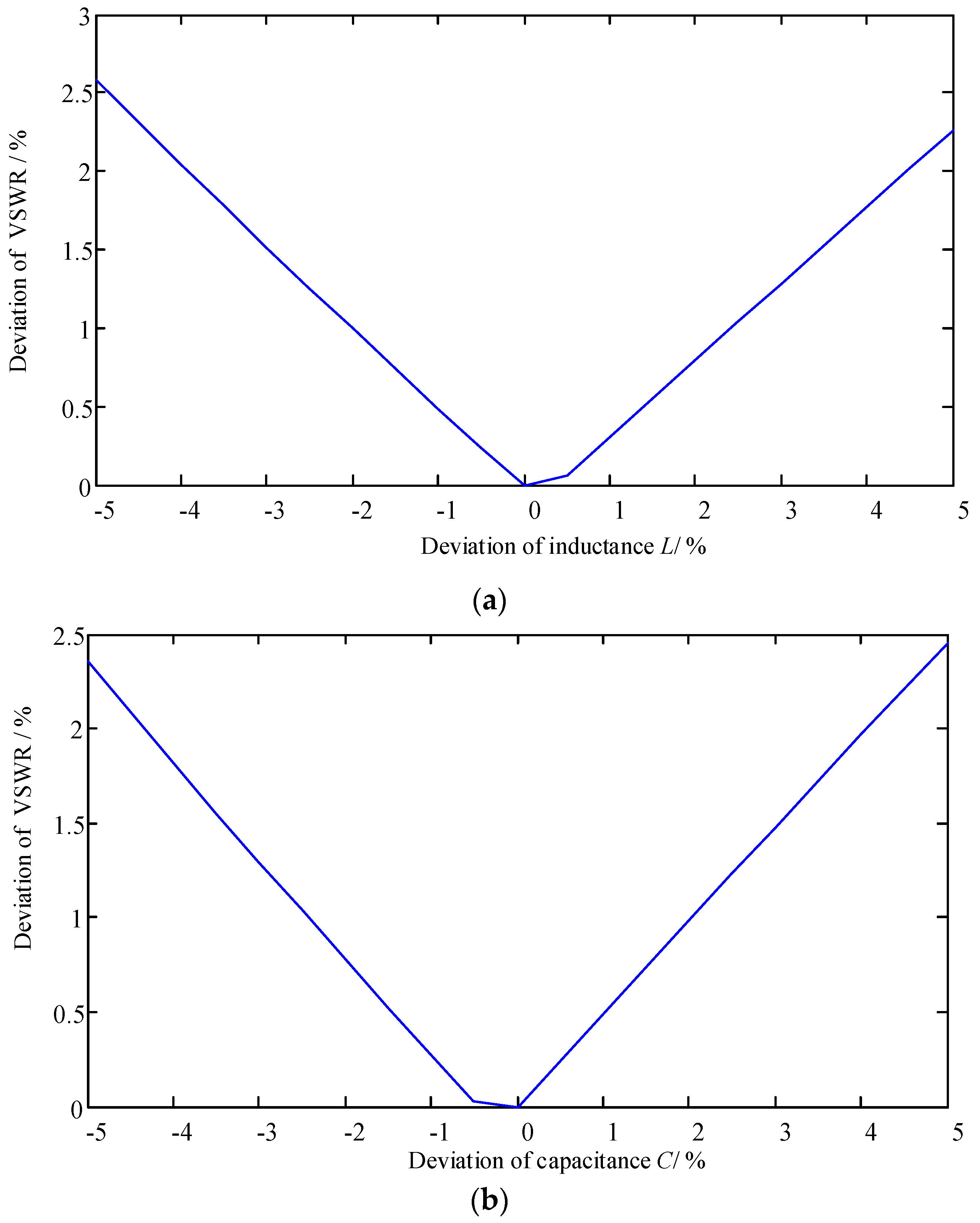
3.3. The Characteristics of the VSWR under Various Fault Conditions

The VSWR may be subject to change, depending on the resistor installed at the end of the grounding line, including the conditions of complete matching of the terminal resistor and incomplete matching terminal resistor. If the resistor completely matches the characteristic impedance, there is no reflection at the end of the grounding line and the VSWR equals 1. Otherwise the VSWR will be greater than 1. In terms of the earth fault on the grounding electrode line, the equivalent resistor should be considered to determine whether the equivalent resistor matches the characteristic impedance or not.
(1) Normal operation with matching terminal resistor
If the end resistor Z L equals to the characteristic impedance Z C , as illustrated in Figure 5. The reflection coefficient and the voltage standing wave ratio can be calculated as:
{ Γ L = 0 V S W R = 1 ,
It is shown that that there is no reflection at the end of the grounding line and the voltage amplitude remains constant along the whole grounding line.
(2) Normal operation with mismatching terminal resistor
If the end resistor Z L does not equal to the characteristic impedance Z C , i.e., the terminal resistor mismatches the characteristic impedance, the reflection coefficient and voltage standing wave ratio can be calculated as:
{ Γ L 0 V S W R > 1 ,
Let V r e a l and V m e a s be the VSWRs calculated with the actual line parameters and the measured line parameters. The difference between V m e a s and V r e a l caused by the variation of L and C can be represented as follows after neglecting the third and higher order terms.
V m e a s V r e a l = V r e a l ( L r , C r ) L ( L m L r ) + V r e a l ( L r , C r ) C ( C m C r ) + 1 2 2 V r e a l ( L r , C r ) L 2 ( L m L r ) 2 + 2 V r e a l ( L r , C r ) L C ( L m L r ) ( C m C r ) + 1 2 2 V r e a l ( L r , C r ) C 2 ( C m C r ) 2
According to (19), we can obtain the effect of line parameters variation on VSWR, as shown in Figure 6. It can be seen in Figure 6 that a 5% deviation of inductance or capacitance will result in less than 2.6% deviation of VSWR. That is to say, VSWR is insensitive to the line parameters. The VSWR based electrode line fault supervision technique is more robust.
Assuming that the maximum deviation between the terminal resistor and the characteristic impedance is less than 10%, the reflection coefficient and voltage standing wave ratio are within the following range:
{ Γ L ( 0.0526 , 0.047 ) V S W R [ 1 , 1.11 ) ,
It is shown that when there is a reflection at the end terminal of the grounding line, and the mismatching degree is less than 10%, the maximum VSWR is only 1.11.
(3) Metallic short circuit condition
When a metallic short circuit occurs at any position of the grounding electrode line, the equivalent resistor is zero. According to Equations (7) and (8), the reflection coefficient and VSWR (approaching infinity) are:
{ Γ L = 1 V S W R ,
(4) Non-metallic short circuit with matching terminal resistor
Under this condition, the ground fault via transition resistance occurs with the matching terminal resistor, as shown in Figure 7. Because the terminal load is equal to the characteristic impedance, the equivalent impedance seen from the fault position to the end terminal Z e q can be calculated.
Z e q = Z c Z f Z c + Z f ,
Normally, the characteristic impedance Z C is about 250 Ω, and if the fault transition resistance is in the range of 0–250 Ω, the range of the reflection coefficient and the VSWR would be in the following range:
Z e q [ 0 , 0.5 Z c ] Z L Z c ,
{ Γ L ( 1 ,   0.3333 ) V S W R [ 2 , )
Equation (24) indicates that if the fault transition resistance is equal to the characteristic impedance, the equivalent impedance is half of the characteristic impedance, and the VSWR under this condition is 2, whereas if a metallic earth fault occurs at the end of the grounding line, the VSWR will approach infinity, which is similar to the above condition.
(5) Non-metallic short circuit with mismatching terminal resistor
In case that an earth fault via transition resistance occurs at the middle of the line, say, x = l f (the total length of the grounding line is l), as shown in Figure 8. Under such condition, the equivalent load impedance seen from the fault position to the end terminal Z L e q is:
Z L e q = Z c e γ ( l l f ) + Γ L e γ ( l l f ) e γ ( l l f ) Γ L e γ ( l l f ) ,
Taking the fault transition impedance Z f into consideration, the equivalent impedance Z e q is:
Z e q = Z f Z c ( 1 Γ L 2 ) 2 j Γ L sin 2 β ( l l f ) 1 + Γ L 2 2 Γ L cos 2 β ( l l f ) Z f + Z c ( 1 Γ L 2 ) 2 j Γ L sin 2 β ( l l f ) 1 + Γ L 2 2 Γ L cos 2 β ( l l f ) ,
Thus the reflection coefficient at the converter station is:
Γ L = ( Z f Z c ) ( 1 Γ L 2 ) 2 j Γ L sin 2 β ( l l f ) 1 + Γ L 2 2 Γ L cos 2 β ( l l f ) Z f ( Z f + Z c ) ( 1 Γ L 2 ) 2 j Γ L sin 2 β ( l l f ) 1 + Γ L 2 2 Γ L cos 2 β ( l l f ) + Z f ,
It shows that when the fault position is not at the end terminal of the grounding electrode line, the equivalent impedance is no longer pure resistance. Hence, the reflection coefficient presents complex number characteristics. The amplitude of the reflection coefficient varies periodically with the fault position distance l f . Therefore, the VSWR varies periodically with the fault position distance l f as well.

3.4. High Frequency VSWR-Based Grounding Electrode Line Fault Supervision

The VSWR-based technique for grounding electrode line fault monitoring systems has a similar structure as shown in Figure 1, and can be implemented on an existing ELIS system. The devices, including the injected current source, the blocking filter on both ends of the grounding line, the resistor equal to the characteristic impedance of the electrode line, can be used. The voltage and current at the converter station end of the grounding electrode line are measured by installed PT and CT.
From the above analysis, it can be safely concluded that the VSWR is close to 1 when the electrode line is under normal operation, whereas the VSWR will increase if there are earth faults on the grounding electrode line. Based on the different values under normal and faulty condition, the criteria for fault judgement can be developed:
V S W R = 1 2 ( U s 2 + Z c 2 I s 2 ) + A c 1 2 ( U s 2 + Z c 2 I s 2 ) A c > V S W R s e t ,
where V S W R s e t is the setting value for fault alarm in the proposed fault supervision scheme.
Since the end terminal resistor may not match completely with the characteristics impedance, the VSWR may be greater than 1 even under normal operation. Thus the setting value of VSWR should be greater than 1. Assume that the maximum deviation between the terminal resistor and the characteristic impedance is less than 10%, the maximum value of the VSWR is 1.1. The following setting value of VSWR is suggested:
V S W R s e t = k I × V S W R max _ n o r m a l ,
where, V S W R max _ n o r m a l is the maximum value of VSWR under normal operation, and k I is the reliable coefficient, taking 1.11. Therefore, the setting value of VSWR equals to 1.22.

4. Case Study

4.1. Simulation Model

The verification of the proposed scheme is conducted on a ±800 kV UHVDC project in south-west China with PSCAD/EMTDC simulation. The transmission capacity of this UHVDC project is 8000 MW. The length of the transmission line is 1652 km. The grounding electrode line of this UHVDC project adopts parallel line and the length of the grounding line is 100 km. The parameters of the grounding electrode line are listed in Table 2. The high frequency current source with a frequency of 13.95 kHz is configured at the converter station end to inject current into the grounding electrode line. The blocking filter is installed on both ends of the grounding line to reduce the standing wave effect in high-frequency inflection.
The characteristic impedance of the double electrode lines is Z c = 1 2 L C = 277.4478   Ω . The setting value of the VSWR follows (29). To verify the characteristics of the VSWR under various operation conditions, the case study is performed considering two scenarios: (a) the end terminal resistor completely matches the characteristic impedance; and (b) the terminal resistor does not match the characteristic impedance. Each scenario includes three kinds of operation conditions: normal operation, double-line earth fault, and single-line earth fault. For the earth fault, three different values of fault impedance are considered, which are 0.1 Ω, 100 Ω, and 200 Ω. Table 3 lists the simulation scenarios.

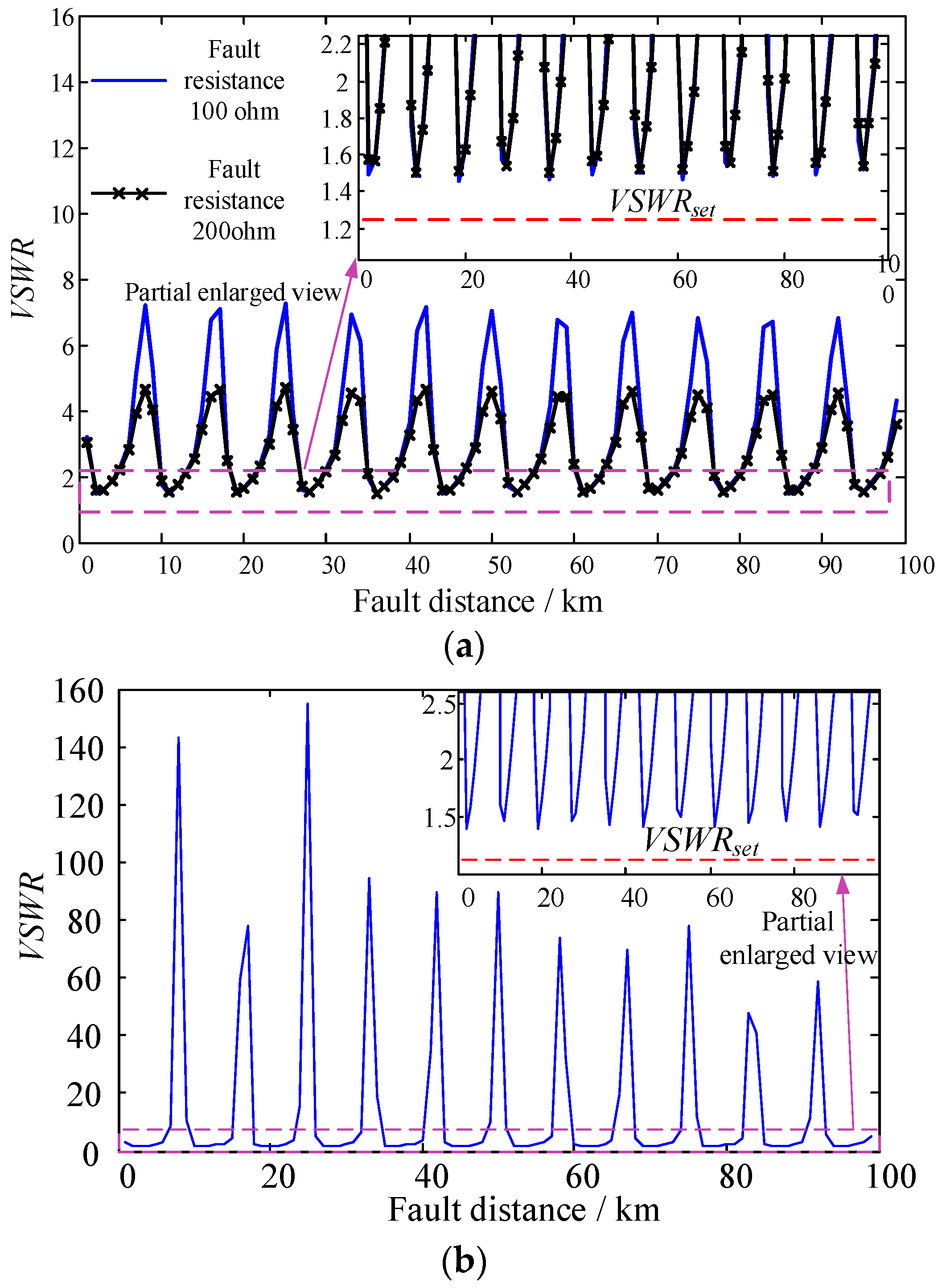
4.2. With Matched Terminal Resistor

When the terminal resistance is 277.48 Ω, the end resistor matches with the characteristic impedance of the double grounding electrode line.
(1) Normal operation condition
Under normal operation condition, the voltage and current at the converter station end are measured to calculate the VSWR:
V S W R = 1.02 < V S W R s e t ,
The VSWR keeps around 1.0, which is less than the VSWR thresholds, thus the proposed VSWR based scheme works correctly.
(2) Double-line earth fault condition
Figure 9 shows the simulated VSWR results under double-line earth fault condition with a matched terminal resistor. The double-line earth fault with metallic earth fault (0.1 Ω), via 100 Ω transition impedance, and via 200 Ω transition impedance are all plotted. The horizontal axis represents the distance from the converter station to the fault position, on the grounding electrode line.
It can be observed from Figure 9 that when non-metallic earth fault occurs on the grounding electrode line, the VSWR decreases with the increase of the transition resistance. The VSWR will also reduce when the fault distance rises. Therefore, the double-line earth fault via a 200 Ω transition resistance on the end terminal of the grounding line results in the lowest VSWR. However, the VSWR under this worst condition is still greater than the threshold, as shown in Figure 9b. Hence the proposed VSWR based technique can perform correctly and reliably under this condition.
(3) Single-line earth fault condition
Figure 10 shows the VSWR results under single-line earth fault condition with matched terminal resistor. The single-line earth fault also includes the metallic earth fault (0.1 Ω), earth fault via 100 Ω transition resistance, and via 200 Ω transition resistance.
Figure 10 shows that the VSWR in single-line earth fault with matched terminal resistor condition is a periodical function of the fault distance because the currents on each grounding electrode line are no longer equal to each other. However, the current and voltage are measured at the station end of the grounding electrode line, and the equivalent VSWR can be calculated following (16). The equivalent VSWRs are still greater than the thresholds, so that the proposed VSWR based technique can operate correctly under such case.

4.3. With Mismatched Terminal

In this case, the terminal resistance is assumed to be 250 Ω, which is about 90.25% of the characteristic impedance.
(1) Normal operation condition
Under normal condition, the voltage and current at the station end are measured to calculate the VSWR:
V S W R = 1.108 < V S W R s e t ,
It is concluded that the VSWR is slightly greater than 1.0 because the end terminal resistor is not completely equal to the characteristic impedance. This result conforms with the analysis in Section 3. However, the VSWR is still less than the setting threshold 1.22. Therefore, the VSWR-based fault supervision device will be operating correctly.
(2) Double-line earth fault condition
Figure 11 shows the VSWR under double-line earth fault condition with mismatched terminal resistor. Similar to the double-line fault with matched terminal resistor, the double-line earth fault with mismatched terminal resistor also includes the metallic earth fault (0.1 Ω), the earth fault via 100 Ω transition resistance, and via 200 Ω transition resistance.
Figure 11 indicates that with mismatched terminal resistance, the VSWR decreases with the raise of the transition resistance, and with the raise of the fault distance. When non-metallic short circuit fault occurs, the VSWR varies periodically with the fault distance, which is in accordance with the above analysis in Section 3. The VSWR under non-metallic earth fault with 200 Ω transition resistance at the end terminal of the grounding electrode line is still greater than the threshold value 1.22. The proposed VSWR technique will operate correctly.
(3) Single-line earth fault condition
Figure 12 presents the simulated VSWR for different fault positions under single-line earth fault condition with mismatched terminal resistance. Similarly, the single-line earth fault includes metallic earth fault (0.1 Ω), the earth fault via 100 Ω transition resistance, and via 200 Ω transition resistance.
It can be seen from Figure 12 that the VSWR also varies periodically with the fault distance l f . The VSWRs in different conditions are still greater than the setting thresholds therefore the proposed scheme works correctly.

4.4. Summary

From the simulations above, it can be concluded that the proposed VSWR-based technique for grounding electrode line fault supervision will not act under normal operation condition no matter whether the terminal resistor is matched or not. The proposed technique can reliably identify both the metallic short circuit faults and non-metallic short circuit faults. The protection range covers the total length of the grounding electrode line.

5. Conclusions

This paper proposes a novel electrode line fault supervision strategy based on high-frequency VSWR for UHVDC transmission projects. Similar to existing high-frequency impedance technique devices, the high frequency current is injected to the electrode line at the converter station end. By measuring the voltage and current, the VSWR can be calculated. Theoretical analysis indicates that the VSWR of the grounding line equals to 1 under normal operation with the matching terminal resistance. When a short circuit occurs on the grounding line, the VSWR will be greater than 1. Simulation results indicate that the proposed technique can reliably identify the grounding electrode line faults and has great anti-fault impedance capability. Meanwhile, under normal operation, the proposed strategy will work reliably, even with mismatching terminal resistors.

Acknowledgments

This work presented in this paper was supported by China Postdoctoral Science Foundation: No. 2015M582543 and by China Postdoctoral Science Foundation: No. 2016M592659.

Author Contributions

All authors have contributed equally to this manuscript. More specifically, Yufei Teng designed the methodology and wrote part of the paper. Xiaopeng Li and Qi Huang performed the simulations and revised the paper. Yifei Wang and Shi Jing contributed specifically to the introduction and conclusion sections of the paper. Zhenchao Jiang and Wei Zhen provided important comments on the paper’s structure.

Conflicts of Interest

The authors declare no conflict of interest.

References

  1. Akhmatov, V.; Callavik, M.; Franck, C.M.; Rye, S.E.; Ahndorf, T.; Bucher, M.K.; Muller, H.; Schettler, F.; Wiget, R. Technical guidelines and prestandardization work for first HVDC grids. IEEE Trans. Power Deliv. 2014, 29, 327–335. [Google Scholar] [CrossRef]
  2. Hammons, T.J.; Woodford, D.; Loughtan, M.; Chamia, M. Role of HVDC transmission in future energy development. IEEE Power Eng. Rev. 2000, 20, 10–25. [Google Scholar] [CrossRef]
  3. Wei, Z.; Yuan, Y.; Lei, X.; Wang, H.; Sun, G.; Sun, Y. Direct-current predictive control strategy for inhibiting commutation failure in HVDC converter. IEEE Trans. Power Syst. 2014, 29, 2409–2417. [Google Scholar] [CrossRef]
  4. Li, S.; Haskew, T.A.; Xu, L. Control of HVDC light system using conventional and direct current vector control approaches. IEEE Trans. Power Electr. 2010, 25, 3106–3118. [Google Scholar]
  5. Pan, Z.; Wang, X.; Tan, B.; Zhu, L.; Liu, Y.; Liu, Y.; Wen, X. Potential compensation method for restraining the DC bias of transformers during HVDC monopolar operation. IEEE Trans. Power Deliv. 2014, 31, 103–111. [Google Scholar] [CrossRef]
  6. Li, W.; Liu, L.; Zheng, T.; Huang, G.; Shi, H. Research on effects of transformer DC bias on negative sequence protection. In Proceedings of the 2011 International Conference on Advanced Power System Automation and Protection (APAP), Beijing, China, 16–20 October 2011; pp. 1458–1463.
  7. Yuan, S.; Gong, X.; Luo, Y. Design of UHVDC earth electrode. In Proceedings of the 2014 International Conference on Power System Technology, Chengdu, China, 20–22 October 2014; pp. 2217–2220.
  8. Yang, G.; Zhu, T.; Wei, L.; Li, L. Research on the faults of electrode line of HVDC transmission system in monopolar ground return operation. Power Syst. Prot. Control 2009, 37, 45–49. [Google Scholar]
  9. Xiao, Y.; Niu, B.; Shang, C.; Lin, Z.; Lu, Y.; Fan, L.; Li, S. A proposal for fast tripping grounding electrode line fault of HVDC. Autom. Electr. Power Syst. 2009, 33, 107–109. [Google Scholar]
  10. Cheng, J.; Xu, Z. Protection characteristics of HVDC common grounding electrode lines. Autom. Electr. Power Syst. 2012, 36, 77–82. [Google Scholar]
  11. Zeng, X.; Zhang, X.; Yang, T.; Deng, S. Improvement measures of electrodes line unbalance protection for HVDC system. Power Syst. Prot. Control 2014, 42, 132–136. [Google Scholar]
  12. Wang, W.; Gervais, Y.; Mukhedkar, D. Probabilistic evaluation of human safety near HVDC ground electrode. IEEE Trans. Power Deliv. 1986, 1, 105–110. [Google Scholar] [CrossRef]
  13. Teng, Y.; Wang, Y.; Jiao, Z.; Zhang, C.; Pang, G. Impedance monitoring scheme for ground electrode line of ultra-high voltage DC transmission system. Trans. China Electrotech. Soc. 2016, 31, 157–163. [Google Scholar]
  14. Teng, Y.; Tang, Y.; Zhou, B.; Jiao, Z.; Pang, G. Monitoring scheme for UHVDC ground electrode line fault on the basis of high-frequency voltage variation. High Volt. Eng. 2016, 42, 73–78. [Google Scholar]
  15. ABB. 1JNL100054-633, Electrode Line Impedance Supervision; ABB: Vasteras, Sweden, 2002. [Google Scholar]
  16. IEEE Standard 1893TM-2015. IEEE Guide for the Measurement of DC Transmission Line and Earth Electrode Line Parameters; Institute of Electrical and Electronics Engineers (IEEE): Piscataway, NJ, USA, 2016.
Figure 1. The ELIS device in a typical bipolar UHVDC system.
Energies 10 00309 g001
Figure 2. Typical operation characteristics of ELIS in UHVDC system.
Energies 10 00309 g002
Figure 3. The effect of line parameters variation on the reference impedance. (a) Effect of inductance variation on VSWR; (b) Effect of capacitance variation on VSWR.
Energies 10 00309 g003
Figure 4. Distributed parameter circuit of a power transmission line.
Energies 10 00309 g004
Figure 5. Matching terminal resistor at the earth end.
Energies 10 00309 g005
Figure 6. The effect of line parameters variation on VSWR. (a) Effect of inductance variation on VSWR; (b) Effect of capacitance variation on VSWR.
Energies 10 00309 g006
Figure 7. Non-metallic short circuit with matching terminal resistor.
Energies 10 00309 g007
Figure 8. Non-metallic short circuit with mismatching terminal resistor.
Energies 10 00309 g008
Figure 9. The VSWR for different fault position of double-line earth fault with matched terminal resistor. (a) the transition resistance is 0.1 Ω; (b) the transition resistance are 100 Ω and 200 Ω, respectively.
Energies 10 00309 g009
Figure 10. The VSWR for different fault position of single-line earth fault with matched terminal resistor. (a) the transition resistance are 100 Ω and 200 Ω, respectively; (b) the transition resistance is 0.1 Ω.
Energies 10 00309 g010
Figure 11. The VSWR for different fault position of double-line earth fault with mismatched terminal resistor. (a) the transition resistance are 100 Ω and 200 Ω, respectively; (b) the transition resistance is 0.1 Ω.
Energies 10 00309 g011
Figure 12. The VSWR for different fault position of single-line earth fault with mismatched terminal resistor. (a) the transition resistance are 100 Ω and 200 Ω, respectively; (b) the transition resistance is 0.1 Ω.
Energies 10 00309 g012
Table 1. The real values and measured values on grounding electrode line.
ValuesL (mH/km)R (ohm/km)C (uF/km)
Real value2.37090.26260.007638
Measured value2.37090.26260.007714
Table 2. Parameters of single grounding electrode line in case study.
ParametersL (mH/km)R (ohm/km)C (uF/km)
Values2.37090.26260.0077
Table 3. Simulation scenarios in case study.
Simulation ScenariosOperation Conditions
With Matched terminal resistorNormal operationDouble-line earth faultSingle-line earth fault
0.1 Ω/100 Ω/200 Ω0.1 Ω/100 Ω/200 Ω
With mismatched terminal resistorNormal operationDouble-line earth faultSingle-line earth fault
0.1 Ω/100 Ω/200 Ω0.1 Ω/100 Ω/200 Ω

